

Page 1
1
INTRODUCTION
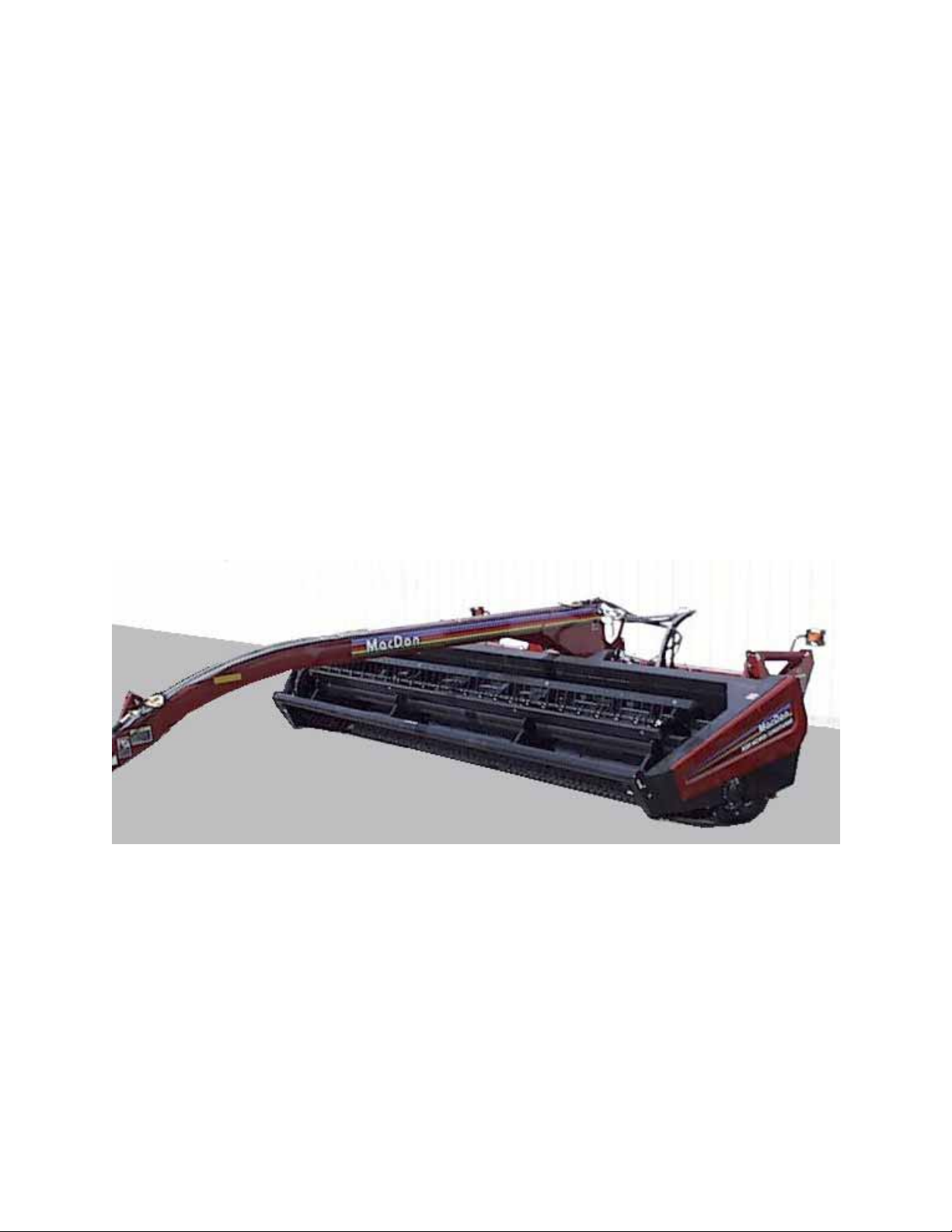
Your new MacDon Model 5020 Power-Tongue Windrower is designed to cut, condition and lay in
windrows, a wide variety of grasses and hay crops.
Use this manual as your f irst sour ce of inf ormation about th e mac hine. If you foll ow the instruc tions give n
in this manual, your Windrower will work well for many years.
The manual contains instructions for "Safety", "Operation", and "Maintenance/Service". In addition,
"Unloading and Assembly" information is given towards the back of this book.
CAREFULLY READ ALL THE MATERIAL PROVIDED BEFORE ATTEMPTING TO UNLOAD,
ASSEMBLE, OR USE THE MACHINE.
Use the Table of Contents and the Index to guide you to s pecific areas. Study the T able of Contents to
familiarize yourself with how the material is organized.
Keep this manual handy for frequent reference and to pass on to new operators or owners. Call your
Dealer if you need ass istance, infor mation, or add itional cop ies of this m anual. A manual s torage case is
provided on the primary drive shield at rear of main frame.
NOTE: Right ha nd (R/H) and left hand (L/H) designations are determined from the operator’s position,
facing forward.
Page 2

2
TABLE OF CONTENTS
PAGE
INTRODUCTION ..................................................................................................................................1
SERIAL NUMBER LOCATION.............................................................................................................4
SAFETY
Safety Alert Symbol .........................................................................................................................5
Signal Words ...................................................................................................................................5
Safety Signs................................................................................................................... ................6, 7
General Farm Safety .......................................................................................................................8
SPECIFICATIONS
Windrower..................................................................................................................................... 9,10
Tractor Requirements.....................................................................................................................10
Hardware Torque Specifications ....................................................................................................11
Hydraulic Fitting Torque Specifications..........................................................................................12
OPERATION
Your Responsibilities as an Owner/Operator .................................................................................13
To the New Operator ......................................................................................................................13
Preparing the Tractor......................................................................................................................14
Preparing the Windrower................................................................................................................15
Attaching Windrower to Tractor................................................................................................... 16,17
Detaching Windrower from Tractor.................................................................................................17
Break-In Period...............................................................................................................................18
Pre-Starting Checks: Annual ..........................................................................................................19
Pre-Starting Checks: Daily..............................................................................................................20
Operate Correctly ...........................................................................................................................21
Engaging the PTO ..........................................................................................................................21
Lift Cylinder Stop (Raising and Lowering the Machine) .................................................................22
Steering...........................................................................................................................................23
180
° Turn........................................................................................................................................24
Turning Square Corners.................................................................................................................25
Operating Variables..................................................................................................................... 25-33
Lean Bar Position .........................................................................................................................26
Ground Speed ..............................................................................................................................26
Reel Speed...................................................................................................................................27
Reel Position.............................................................................................................................. 27,28
Cutting Height (Skid Plates) .........................................................................................................29
Header Angle................................................................................................................................30
Header Flotation ...........................................................................................................................31
Feed Pan / Rock Drop Tine Position ............................................................................................31
Roll Gap........................................................................................................................................32
Forming Shields............................................................................................................................33
Rear Deflector.............................................................................................................................33
Haying Tips:................................................................................................................................. 34,35
Topsoil Moisture ...........................................................................................................................34
Climate and Topography ..............................................................................................................34
Windrow Characteristics...............................................................................................................35
Running Tractor Tire on Previously Cut Windrow ........................................................................35
Raking and Tedding......................................................................................................................35
Chemical Drying Agents...............................................................................................................35
Unplugging the Windrower: Sickle..................................................................................................36
Unplugging the Windrower: Rolls ...................................................................................................36
Shut-Down Procedure ....................................................................................................................37
Transporting the Windrower: Towing..............................................................................................37
Transporting the Windrower: Flatbed .............................................................................................38
Storage Procedure..........................................................................................................................39
Page 3

TABLE OF CONTENTS
PAGE
MAINTENANCE/SERVICE
Service Procedures.........................................................................................................................39
Recommended Fluids and Lubricants............................................................................................40
Capacities of Enclosed Drives and Reservoir.................................................................................40
Bearing Installation .........................................................................................................................40
Closing Drive Shields......................................................................................................................41
Greasing the Windrower.............................................................................................................. 41-44
Center Link Ball Joints ....................................................................................................................44
Spring Pivots...................................................................................................................................44
Hitch Pin Lock Nut ..........................................................................................................................44
Hydraulics................................................................................................................................... 45,46
System Safety...............................................................................................................................45
Hoses and Lines...........................................................................................................................45
Hydraulic Reservoir.................................................................................................................... 45,46
Hydraulic Oil Filter.........................................................................................................................46
Electrical........................................................................................................................................46
Sickle and Sickle Drive..............................................................................................................47-51
Sickle Lubrication..........................................................................................................................47
Sickle Sections..............................................................................................................................47
Sickle Removal.............................................................................................................................47
Sickle Head Needle Bearing Installation.......................................................................................48
Sickle Installation..........................................................................................................................48
Guards..........................................................................................................................................49
Excessive Breakage .....................................................................................................................49
Sickle Hold-Downs........................................................................................................................49
Sickle Drive Belt Tension..............................................................................................................50
Sickle Drive Belt Replacement .....................................................................................................50
Wobble Box Maintenance.............................................................................................................51
Reel and Reel Drive ......................................................................................................................52
Reel Drive Chain Lubrication........................................................................................................52
Reel Drive Chain Tension.............................................................................................................52
Reel Drive Belt Tension................................................................................................................52
Reel Tines.....................................................................................................................................52
Auger and Auger Drive..............................................................................................................53-55
Auger Position...............................................................................................................................53
Stripper Bars.................................................................................................................................54
Auger Drive Chain Lubrication......................................................................................................55
Auger Drive Chain Tension...........................................................................................................55
Rolls and Roll Drive................................................................................................................... 56,57
Roll Drive Chain Tension..............................................................................................................56
Roll Drive Chain Case Lubricant...................................................................................................56
Roll Timing....................................................................................................................................57
Roll Drive Chain Removal & Installation .................................................................................... 58,59
Wheels and Tires ..........................................................................................................................60
Wheel Bolts...................................................................................................................................60
Wheel Removal ............................................................................................................................60
Tire Inflation..................................................................................................................................60
Maintenance Schedule ...................................................................................................................61
Maintenance Record.......................................................................................................................62
TROUBLE SHOOTING..................................................................................................................... 63-66
OPTIONS AND ATTACHMENTS
Additional Skid Plates .....................................................................................................................67
PTO Conversion Kits ......................................................................................................................67
Tall Crop Kit....................................................................................................................................67
Stub Guard Conversion Kit.............................................................................................................68
Hydraulic Header Angle Kits...........................................................................................................68
Reel Bat Replacement Kits.............................................................................................................68
UNLOADING & ASSEMBLY............................................................................................................. 69-77
INDEX............................................................................................................................................... 78,79
3
Page 4
SERIAL NUMBER LOCATIONS
Record the serial number in the space provided.
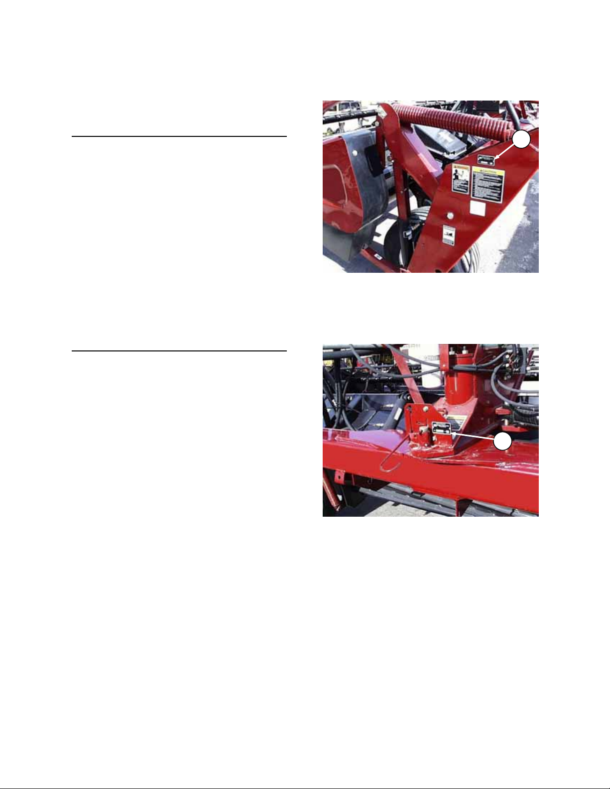
Windrower:
Serial number plate (A) is located on the s ide of
the left hand end frame.
Tongue:
Serial number plate (B) is located at rear of
tongue.
NOTE: When ordering parts and service, be sure
to give your dealer the complete and proper serial
number.
SERIAL PLATE LOCATION: WINDROWER
A
B
SERIAL PLATE LOCATION: TONGUE
4
Page 5

SAFETY
SAFETY ALERT SYMBOL
Why is SAFETY important to you?
3 BIG REASONS · ACCIDENTS COST
SIGNAL WORDS
Note the use of the signal words DANGER, WARNING, and CAUTION with safety messages. The appropriate
signal word for each message has been selected using the following guidelines:
DANGER – Indicates an imminently hazardous situation that, if not avoided, will result in death or
serious injury.
WARNING – Indicates a potentially hazardous situation that, if not avoided, could result in death or
serious injury. It is also used to alert against unsafe practices.
CAUTION – Indicates a potentially hazardous situation that, if not avoided, m ay result in m inor or
moderate injury. It is also used as a reminder of good safety practices.
This safety alert symbol indicates important safety messages in this
manual and on safety signs on the machine.
This symbol means:
ATTENTION!
BECOME ALERT!
YOUR SAFETY IS INVOLVED!
Carefully read and follow the safety message accompanying this symbol.
· ACCIDENTS DISABLE AND KILL
· ACCIDENTS CAN BE AVOIDED
5
Page 6
SAFETY
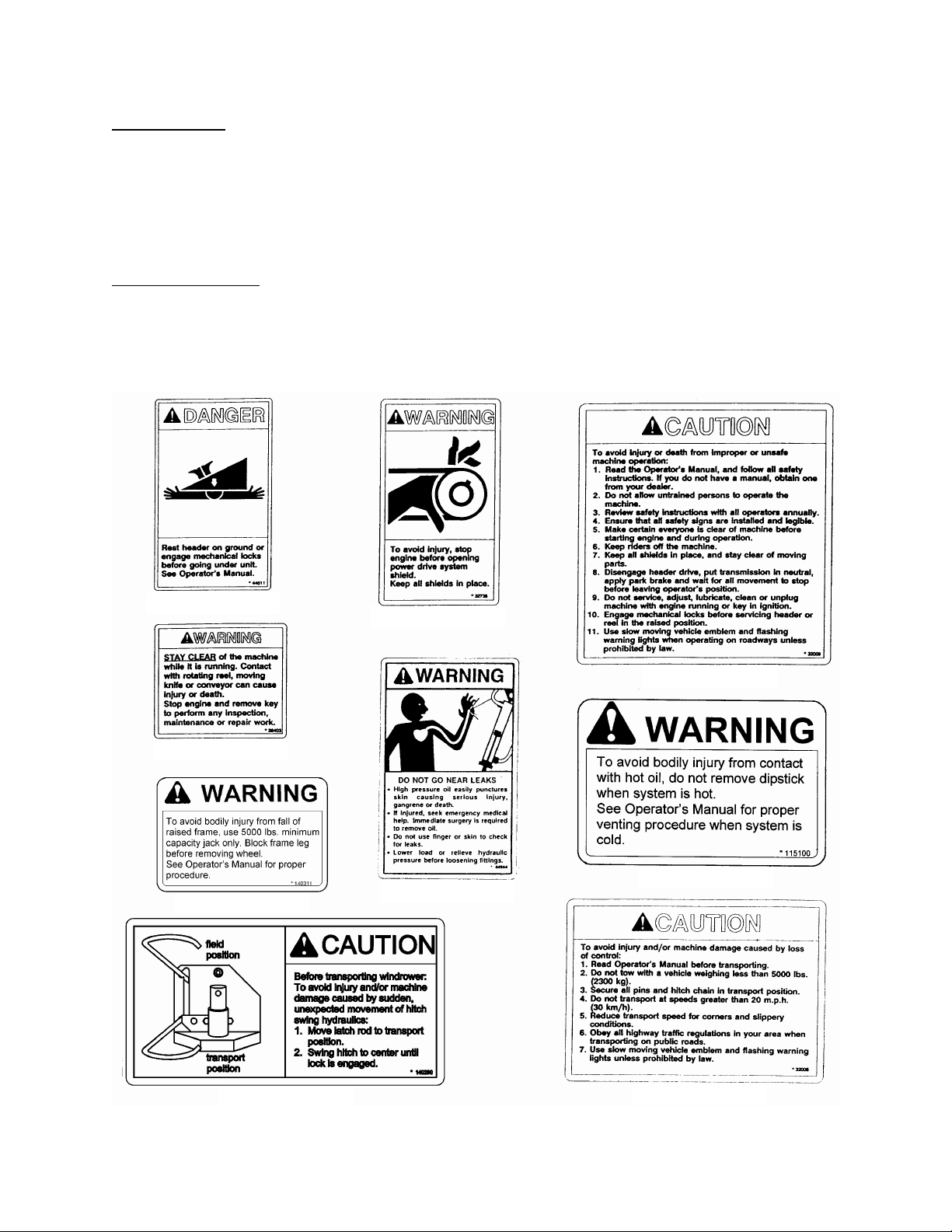
SAFETY SIGNS
• The safety signs reproduced below appear on the windrower at the locations shown on page 7.
• Keep safety signs clean and legible at all times
• Replace safety signs that are missing or become illegible.
• If original parts on which a safety sign was installed are replaced, be sure the repair part also bears the
current safety sign.
• Safety signs are available from your Dealer Parts Department.
To install safety signs
1. Be sure the installation area is clean and dry.
2. Decide on the exact location before you remove the decal backing paper.
3. Remove the smaller portion of the split backing paper.
4. Place the sign in position and slowly peel back the remaining paper, smoothing the sign as it is applied.
5. Small air pockets can be smoothed out or pricked with a pin.
:
A - # 44611
D - # 28403
E - # 140311
B - # 32738
C - # 32009
G - # 115100
F - # 44944
H - # 140290
6
J - # 32008
Page 7
SAFETY
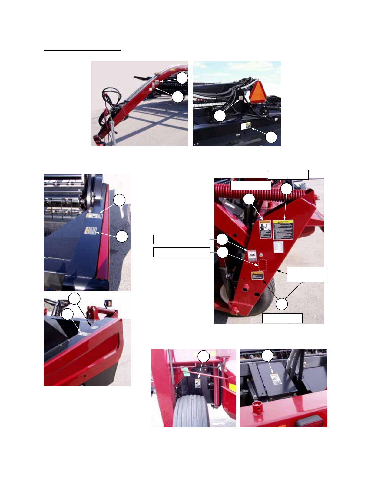
SAFETY SIGN LOCATIONS
J
F
TONGUE & FRAME BACK TUBE
G
H
LEFT ONLY
LEFT ONLY
B
D
D
B
LEFT & RIGHT (14’ & 16’)
LEFT & RIGHT (12’)
A
A
F
LEFT & RIGHT
C
BACK SIDE OF
LEG FOR 12’
E
MAIN FRAME
B
B
HEADER END FRAMES
12’ UNIT 14’ & 16’ UNITS
PRIMARY DRIVE SHIELD
7
Page 8

SAFETY
GENERAL SAFETY
The following are genera l farm safet y
precautions that should be part of
your operating procedure for all
types of machinery.
1. Protect yourself.
When assembling, operating and servicing
machinery, wear all the protective clothing
and personal safety devices that COULD be
necessary for the job at hand. Don’t take
chances.
You may need:
· a hard hat.
· protective shoes with slip resistant soles.
· protective glasses or goggles.
· heavy gloves.
· wet weather gear.
· respirator or filter mask.
· hearing protection. Be aware that
prolonged exposure to loud noise can
cause impairment or loss of hearing.
Wearing a suitable hearing protective
device such as ear muff s (A) or ear plugs
(B) protects against objectionable or loud
noises.
2. Provide a first-aid
kit for use in case
of emergencies.
3. Keep a fire
extinguisher on the
machine. Be sure
the extinguisher is properly mai ntain ed an d
be familiar with its proper use.
4. Keep young children away from machinery
at all times.
5. Be aware that accidents often happen whe n
the operator is tired or in a hurry to get
finished. Take the time to consider the
safest way. Never ignore warning signs of
fatigue.
A
B
6. Wear close-fitting clothing
7. Keep hands, feet,
8. Keep all shields in
9. Use only service and repair parts mad e or
10. Do not modify the machine. Unauthorized
11. Stop engine and remove key from ignition
12. Keep the area used for
13. Use adequate light for the job at hand.
14. Keep machinery clean. Straw and chaff on a
15. Never use gasoline, naphtha or any volatile
16. When storing machinery, cover sharp or
and cover long hair. Never
wear dangling items such
as scarves or bracelets.
clothing and hair
away from moving
parts. Never attempt
to clear obstructions
or objects from a
machine while the
engine is running.
place. Never alter or remove safety
equipment. Make sure driveline guards can
rotate independently of the shaft and can
telescope freely.
approved by the equipment manufacturer.
Substituted parts may not meet strength,
design, or safety requirements.
modifications may impair the function
and/or safety and affect machine life.
before leaving operator's seat for any
reason. A child or even a pet c ould engage
an idling machine.
servicing machinery
clean and dry. Wet or
oily floors are slippery .
Wet spots can be
dangerous when
working with electrical
equipment. Be sure all
electrical outlets and
tools are properly grounded.
hot engine are a fire hazard. Do no t all ow oi l
or grease to accumulate on service
platforms, ladders or controls. Clean
machines before storage.
material for cleaning purposes. These
materials may be toxic and/or flammable.
extending components to prevent injury
from accidental contact.
8
Page 9

SPECIFICATIONS
DIMENSIONS
Overall Width:
Transport Position 13.5 ft. (4103 mm) 15.5 ft. (4713 mm) 17.5 ft. (5323 mm)
Field Position 18.1 ft. (5531 mm) 21.1 ft. (6446 mm) 24.1 ft. (7360 mm)
Overall Length:
Transport Position 20.7 ft. (6320 mm) 22.1 ft. (6740 mm) 24.9 ft. (7573 mm)
Field Position 15.8 ft. (4816 mm) 16.3 ft. (4975 mm) 18.2 ft. (5557 mm)
Overall Height
Transport Position 6.2 ft. (1896 mm)
Field Position 6.2 ft. (1896 mm)
Weight 5900 lbs. (2675 kg) 6250 lbs. (2835 kg) 6623 lbs. (3005 kg)
CUTTERBAR
Cutterbar Width 12.25 ft. (3734 mm) 14.25 ft. (4343 mm) 16.25 ft. (4953 mm)
Cutting Height (on skids) 1.5 to 4 in. (38 to 100 mm)
at 8° guard angle
Guard (Header) Angle (adjustable) 6° to 11.5° below horizontal
Cutterbar Range 2.0 in. below ground to 21 in. above ground
at 8° guard angle (to guard tip) (-50 mm to +533 mm)
MAIN DRIVE
Rear Countershaft Speed 1156 RPM *
SICKLE
Drive Type Belt driven wobble box (enclosed oil bath )
Speed 1560 strokes or 780 cycles per minute *
Stroke 3 in. (76 mm)
Sections Over-serrated, low shoulder
Guards Double heat treated, forged steel
REEL
Drive Type V-belt drive from R/H auger shaft
Reel Type 5 bats (4 or 6 bats optional),
Radius 22 in. (1560 mm) to finger tip
Speed 72 RPM as assembled / 59 RPM with
NOTE: Specifications listed only under 14 ft. column are common to all sizes.
* All speeds are in no-load condition at rated tractor RPM.
12 FT. 14 FT. 16 FT.
540 or 1000 RPM PTO tractor driven pump
to hydraulic motor driving primary shaft
to chain final drive
replaceable steel pick-up tines,
cam action, polymer tine tube bearings
pulley exchange / 66 RPM optional *
9
Page 10

SPECIFICATIONS
AUGER
Drive Type Chain final drive
Overload Protection Hydraulic motor
Auger Type 20 in. (508 mm) diameter
Auger Speed 245 RPM *
CONDITIONER ROLLS
Drive Type Drivelines from enclosed oil bath chain dri ve
Roll Type Helical intermeshing steel “V” bars
Roll Diameter 8.75 in. (222 mm)
Roll Length 93 in. (2360 mm)
Roll Speed 827 RPM *
WHEELS
Tread Width 119 in. (3030 mm) 143 in. (3640 mm) 143 in. (3640 mm)
Tires 31 x 13.5 - 15 NHS 8 ply Terra-Rib
Tire Pressure 30 psi (207 kPa)
MATERIAL DISCHARGE
Minimum Width 30 in. (760 mm)
Maximum Width 92 in. (2346 mm)
Rear Fluffing Shield Adjustable
OPERATING SPEED
Recommended Field Speed 5 mph (8 km/h)
Recommended Transport Speed 20 mph (30 km/h)
TRACTOR REQUIREMENTS
Minimum Power 60 hp (45 kw) 75 hp (56 kw) 90 hp (68 kw)
Drawbar Capacity Must Exceed 1300 lbs. (5785 N) 1030 lbs. (4580 N) 1100 lbs. (4895 N)
PTO 540 or 1000 RPM - ASAE standard location
Hydraulic Capacity 1750 psi (12000 kPa), two hy drauli c circuits
* All speeds are in no-load condition at rated tractor RPM.
(SPECIFICATIONS AND DESIGN ARE SU BJECT TO CHANGE WITHOUT NOTICE OR OBLIGATION TO
REVISE UNITS PREVIOUSLY SOLD.)
12 FT. 14 FT. 16 FT.
variable pitch, center feed
10
Page 11
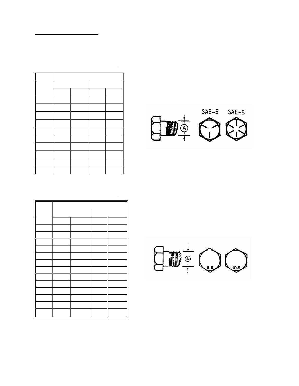
TORQUE SPECIFICATIONS
8.8
10.9
N·m
[lb-ft]
N·m
[lb-ft]
M3
0.5
[.4]
1.8
[1.3]
M4
3
[2.2]
4.5
[3.3]
M5
6
[4]
9
[7]
M6
10
[7]
15
[11]
M8
25
[18]
35
[26]
M10
50
[37]
70
[52]
M12
90
[66]
125
[92]
M14
140
[103]
200
[148]
M16
225
[166]
310
[
229]
M20
435
[321]
610
[450]
M24
750
[553]
1050
[774]
M30
1495
[1103]
2100
[1550]
CHECKING BOLT TORQUE
The tables shown below give correct torque values for various bolts and capscrews. Tighten all bolts to the
torques specified in chart unless otherwise noted throughout this manual. Check tightness of bolts periodically,
using bolt torque chart as a guide. Replace hardware with the same strength bolt.
ENGLISH TORQUE SPECIFICATION
Bolt
Dia.
"A"
1/4" 12 [9] 15 [11]
5/16" 24 [18] 34 [25]
3/8" 43 [32] 56 [41]
7/16" 68 [50] 95 [70]
1/2" 102 [75] 142 [105]
9/16" 149 [110] 202 [149]
5/8" 203 [150] 271 [200]
3/4"
7/8" 569 [420] 813 [600]
1" 867 [640] 1205 [890]
METRIC TORQUE SPECIFICATIONS
Bolt
Dia.
"A"
NC Bolt Torque*
SAE 5 SAE 8
N·m [lb-ft] N·m [lb-ft]
359 [265]
Bolt Torque*
495 [365]
M36 2600 [1917] 3675 [2710]
Torque figures indicated above are valid for non-greased or non-oiled threads and heads unless otherwise
specified. Do not grease or oil bolts or capscrews unless specified in this manual. W hen using locking
elements, increase torque values by 5%.
* Torque value for bolts and capscrews are identified by their head markings.
11
Page 12

TORQUE SPECIFICATIONS
8
2
2
2
2
2
1
1
1
8
1
1
1
1
1
1
1
TIGHTENING HYDRAULIC O-RING FITTINGS*
1. Inspect O-ring and seat for dirt or obvious
defects.
2. On angle fittings, back the lock nut off until
washer bottoms out at top of groove.
3. Hand tighten fitting until back up washer or
washer face (if straight fitting) bottoms on face
and O-ring is seated.
4. Position angle fittings by unscrewing no more
than one turn.
5. Tighten straight fittings to torque shown.
6. Tighten angle fittings to torque shown while
holding body of fitting with a wrench.
* The torque values shown are based on
lubricated connections as in reassembly
.
Size
(in.)
3/8
Nut Size
Across
Flats
(in.)
1/2
Thread
7/16 9/16 12
1/2
5/8
9/16 11/16
3/4
7/8
7/8
1-1/16
1-3/16
1-1/4 102 [75]
1-3/8 122 [90]
Torque Value*
Recommended
Turns to Tighten
(after finger
tightening)
N·m [lb-ft] Flats Turns
[6]
[9]
16 [12]
24 [18]
46 [34]
1/3
1/3
1/3
1/3
1/3
62 [46] 1-1/2 1/4
1/6
1/6
TIGHTENING HYDRAULIC FLARE-TYPE
TUBE FITTINGS*
1. Check flare and flare seat for defects that
might cause leakage.
2. Align tube with fitting before tightening.
3. Lubricate connection and hand tighten swivel
nut until snug.
4. To prevent twisting the tube(s), use two
wrenches. Place one wrench on the connector
body and with the second tighten the swivel
nut to the torque shown.
* The torque values shown are based on
lubricated connections as in reassembly.
1-5/16
1-1/2 142 [105] 3/4 1/8
1-5/8 1-7/8 190 [140] 3/4 1/8
1-7/8 2-1/8 217 [160] 1/2 1/12
Tube
O.D.
Size
(in.)
Nut Size
Across
Flats
(in.)
Torque Value*
Recommended
Turns to Tighten
(after finger
tightening)
N·m [lb-ft] Flats Turns
3/16 7/16
1/4 9/16 12
5/16 5/8
3/8 11/16
16 [12]
24 [18]
[6]
[9]
1/6
1/6
1/6
1/6
1/2
5/8
7/8
46 [34]
62 [46]
1/6
1/6
3/4 1-1/4 102 [75] 3/4 1/8
7/8 1-3/8 122 [90] 3/4 1/8
12
Page 13
OPERATION
YOUR RESPONSIBILITIES AS AN OWNER/OPERATOR
CAUTION:
1. It is your responsibility to read and
understand this manual completely before
operating the windrower. Contact your
dealer if an instruction is not clear to you.
2. Fo llow all safety messages in the manual
and on safety signs on the machine.
3. Remember that YOU
Good safety practices protect you and the
people around you.
4. Before allowing anyone to operate the
windrower, for however short a time or
distance, make sure they have been
instructed in its safe and proper use.
5. Review the manual and all safety related
items with all operators annually.
6. Be alert for other operators not using
recommended procedures or not following
safety precautions. Correct these mistakes
immediately, before an accident occurs.
7. Do not modify the machine. Unauthorized
modifications may impair the function
and/or safety and affect machine life.
8. The safety information given in this manual
does not replace safet y codes, insurance
needs, or laws governing your area. Be sure
your machine meets the standards set by
these regulations.
9. Ensure that the tractor is properly equipped
to safely operate the windrow er. This may
include adding ballast according to Tractor
Operator’s Manual requirements for
attachments of this size and mass.
TO THE NEW OPERATOR
It’s natural for an operator to be anxious to get
started with a new machine. Please take the time
to familiarize yourself with the windrower by
reading the Operator’s Manual and safety signs
before attempting operation.
are the key to safety.
13
Page 14
OPERATION
STANDARD DRAWBAR SPECIFICATIONS
PREPARING THE TR ACTOR
1. Select proper tractor size. The minimum po wer
required is: 12 ft. - 60 hp (45 kw)
14 ft. - 75 hp (56 kw)
16 ft. - 90 hp (68 kw)
Tractor drawbar capacity must exceed:
12 ft. – 1300 lb. (5785 N)
14 ft. – 1030 lb. (4580 N)
16 ft. – 1100 lb. (4895 N)
Also, minimum hydraulics required are 1750
psi (12000 kPa) pr essure with double acting,
dual remote capability.
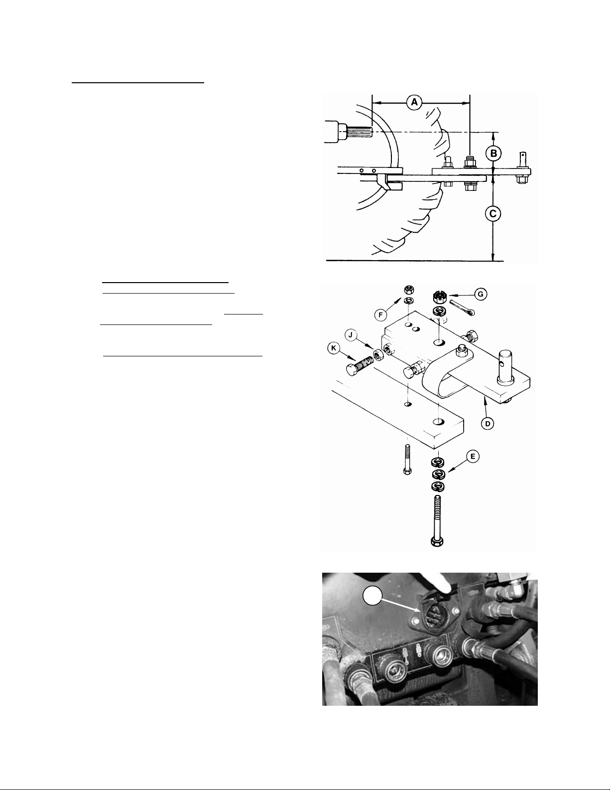
2. Adjust tractor drawbar to meet ASAE Standard
specifications as listed below. An im properly
located drawbar may affect header flotation
and guard angle.
(A) 14 in. (356 mm) for 540 rpm.
16 in. (406 mm) for 1000 rpm.
(B) 6 to 12 in. (152 to 305 mm) with 8 in.
(203 mm) recommended.
(C) 13 to 17 in. ( 330 to 432 m m ) f rom ground
with 16 in. (406 mm) recommended.
3. Secure the drawbar so the hitch pinhole is
directly below the driveline.
NOTE: If the tractor has a three-point hitch,
raise the lower links as high as possible to
prevent damage.
4. Attach the drawbar extension (D) to the tractor
drawbar.
IMPORTANT: To prevent damage to the pump
and hose assembly, do not operate the
machine without the drawbar extension. Use
washers (E) as required depending on drawbar
thickness.
Tighten 5/8 nut (F) to 160 ft.lbs. (215 N·m)
torque.
Tighten 1 inch slotted nut (G) to 630 ft.lbs.
(850 N·m) torque. Further tighten nut (G) to
align slot with hole and install cotter pin.
Back off nuts (J) and turn in four bolts (K) until
snug against tractor drawbar. Tighten nuts (J)
to secure the position.
5. Use proper PTO speed (540 or 1000)
depending on windrower options.
6. Tractor must be equipped with a seven
terminal outlet (H) to supply power to the
windrower's warning lights.
ATTACH DRAWBAR EXTENSION
H
SEVEN TERMINAL ELECTRICAL OUTLET
14
Page 15
OPERATION
CHECK REEL DRIVE BELT TENSION
CHECK HYDRAULIC OIL LEVEL
CHECK SICKL
E DRIVE BELT TENSION,
AND DRIVE BOX LUBRICANT
PREPARING THE WINDROWER
1. Check the tires and inflate if necessary.
Recommended pressure is 30 psi (207 kPa).
CAUTION: When inflating tires, use
a clip-on chuck and extension hose
long enough to allow you to stand
to one side and not facing the tire.
2. Check for proper assembly and adjustment
and make sure all bolts are tightened securely.
3. Check the tension of the reel drive belt and the
sickle drive belt. Adjust if required. See
Maintenance/Service section.
4. Lubricate the machine completely and check
the oil level of the sickle drive box. See
Maintenance/Service section.
5. Check hydraulic oil level at dipstick. Add oil if
required. See Maintenance/Service section.
6. Install quick coupler tips (m atc hing the tractor
to be used) on the remote hydraulic hoses.
STAND TO ONE SIDE WHEN INFLATING TIRES
15
Page 16
OPERATION
ATTACHING WINDROWER TO TRACTOR
CAUTION: Shut off tractor, engage
parking brake and remove key before
working around hitch.
CAUTION: Never attach windrowe r to
tractor rear axle or three-point hitch
arms.
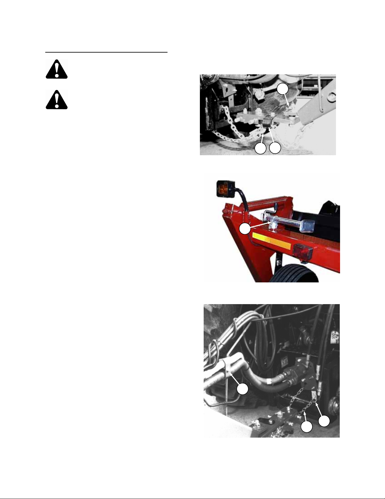
1. Using the jack, raise windrower tongue to clear
the hitch pin in drawbar extension. Position
tractor to align ball joint on tongue with hitch pin
and lower tongue. Secure with lock pin (A).
2. Route hitch chain from windrower through
chain support (B), around drawbar support and
lock hook (C) on chain.
IMPORTANT: Adjust chain length to remove all
slack except what is needed for turns.
3. Remove weight from jack. Pull pin securing
jack and move to storage position (D) on top of
frame tube.
4. NOTE: Pump attachm ent is easier if hitch is
angled to tractor, not straight on.
Slide the hydraulic pump assembly onto the
PTO shaft of the tractor. Adjust the torque arm
(E) so that it rests on the right side of the
drawbar.
IMPORTANT:
• Pump outlets must remain vertical. Loop the
torque arm c hain (F) around the drawbar and
lock the chain in keyhole slot in torque arm
mounting plate.
• To prevent hose damage, route hoses through
guide (G) to provide proper hose arc as shown.
• Full engagement of PTO shaft into pump is
required to prevent damage to pump spline.
Pump should slide 2-1/2" (64 mm) onto shaft.
• The pump must never be keyed or fastened to
the PTO shaft. If the drawbar pin should
become disengaged, the pump must be free to
slip off.
A
B
C
SECURE HITCH PIN AND CHAIN
D
JACK STORAGE
G
F
E
ATTACH PUMP ASSEMBLY
16
Page 17
OPERATION
CONNECT REMOTE HYDRAULICS
ATTACHING WINDROWER TO TRACTOR
(cont’d)
5. Connect remote hydraulic hoses as follows:
a. Connect the two tongue swing hoses (H) s o
that when the tractor control is moved forward,
the swing cylinder will extend, mov ing th e wi ndrower to the right. When the tractor control
handle is moved back, the swing cylinder will
retract, moving the windrower to the left.
b. Connect the two lift cylinder hoses (J) so that
when the tractor control is moved back, the lift
cylinder will extend, raising the header. W hen
the tractor control is moved forward, the lift
cylinder will retract, lowering the header.
6. Connect the windrower wiring harness plug (K)
to outlet on tractor.
DETACHING WINDROWER FROM TRACTOR
CAUTION: To prevent accidental
movement of tractor, shut off engine,
engage parking brake, and remove
key.
To maintain stability, always lower the
machine completely. Block windrower wheels
before detaching from tractor.
Park machine on flat level surface with hitch at
an angle to tractor drawbar (to facilitate pump
detachment).
Move remote cylinder control valve lever back
and forth to relieve stored hydraulic pressure.
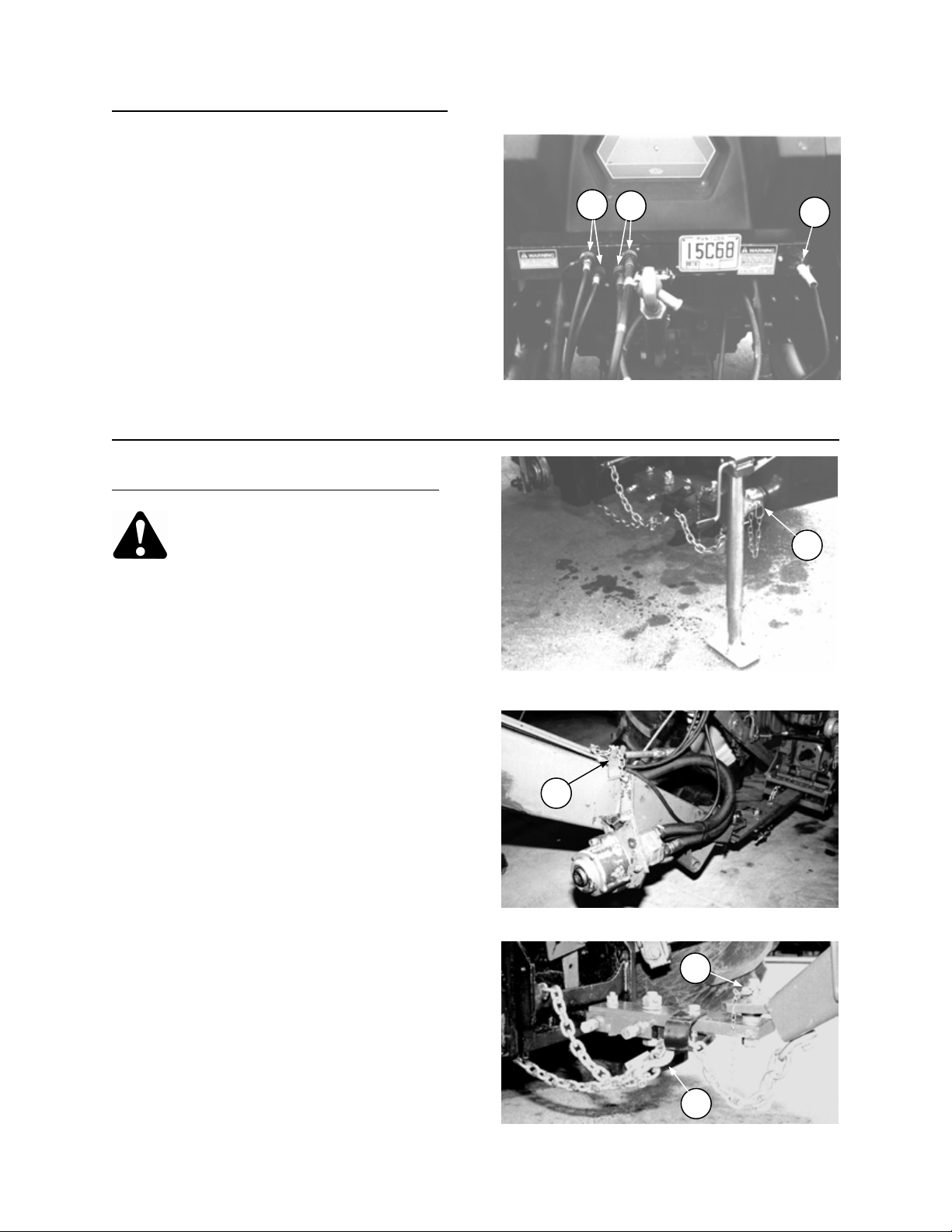
1. Pull pin securing jack and move to working
position (A) at front of tongue.
2. Lower jack to take weight off tractor drawbar.
3. Unlock torque arm chain fr om keyhole slot in
torque arm mounting plate. Remove hydraulic
pump assembly and store at (B).
4. Disconnect hydraulic hoses and electrical
harness. Store with ends off ground.
5. Remove hitch pin lock (C) and unhook chain
(D) from tractor. Wrap chain around windrowe r
tongue for storage. Raise windrower tongue
with jack to clear hitch pin.
6. Slowly drive tractor away from windrower.
H
J
AND ELECTRICAL
MOVE JACK TO WORKING POSITION
B
STORE PUMP ASSEMBLY
C
K
A
D
REMOVE HITCH PIN LOCK AND CHAIN
17
Page 18
OPERATION
AUGER DRIVE BELT & CHAIN TENSION
CHECK REEL DRIVE BELT & CHAIN
BREAK-IN PERIOD
1. After attaching windrower to tractor for the first
time, operate the machine slowly for 5 minut es,
watching and listening FROM THE TRACTOR
SEAT for binding or interfering parts.
CAUTION: Before investigating an
unusual sound or attempting to
correct a problem, shut off tractor,
engage parking brake and remove key.
2. Check wheel bolt torque after 1 hour
operation
and periodically thereafter (at least ever y 100
hours). Torque to 120 ft.lbs. (160 N
⋅m).
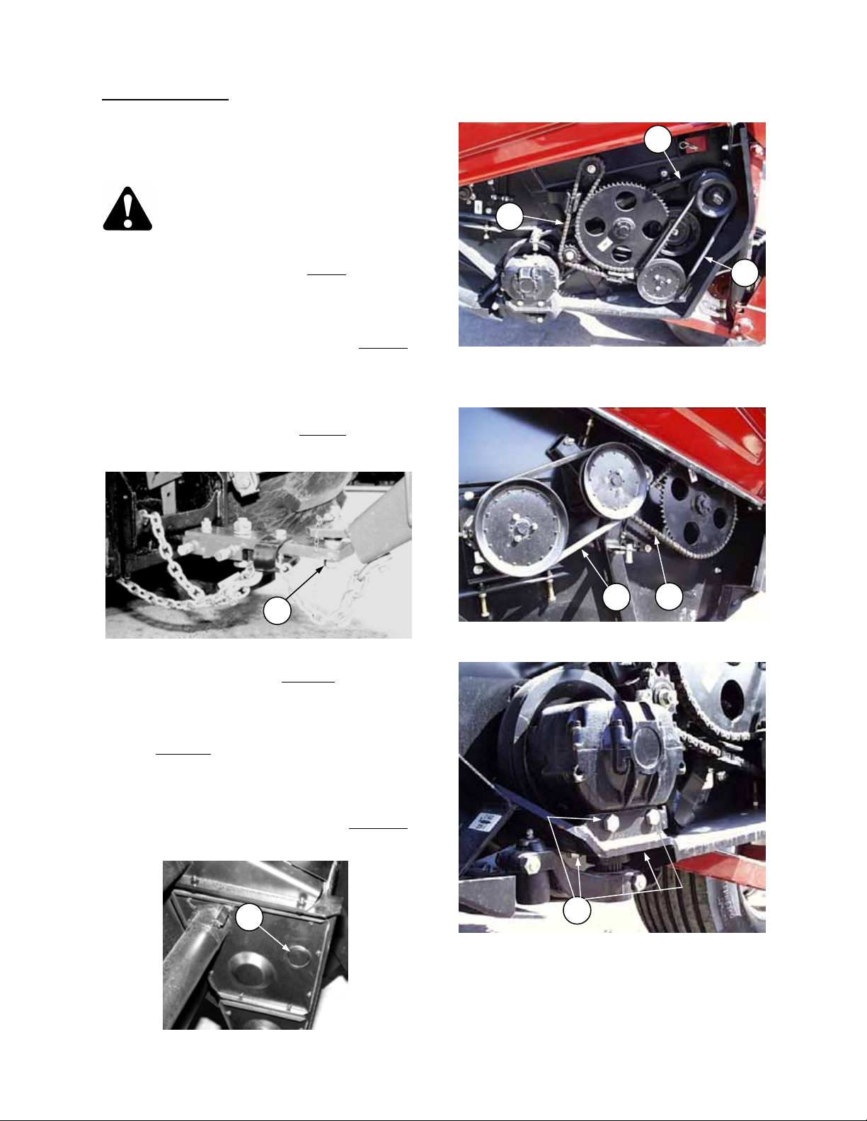
3. Check sickle drive belt (A), auger primary driv e
belt (H) and reel drive belt (G) after 5 hours
operation for initial stretch. Tighten as
necessary. (See Maintenance/Service section).
Continue to check the belts periodically for the
first 50 hours.
4. Check hitch pin nut (B) after 5 hours
operation
and every 50 hours thereafter. T orque to 350
ft.lbs. (475 N
⋅m).
B
5. Check hardware after 5 hours
CHECK HITCH PIN LOCK NUT
operation.
Tighten as necessary. See Specifications
section for recommended torques.
6. Tighten the four wobble box mounting bolts (C)
after 10 hours
thereafter. Torque to 200 ft.lbs. (270 N
operation and every 100 hours
⋅m),
starting with the side mounting bolts.
7. Check reel drive chain (D), auger drive chain
(E) and roll drive chain (F) after 10 hours
operation for proper tension and lubrication.
See Maintenance/Service section.
F
CONTINUED NEXT PAGE…..
A
E
H
CHECK SICKLE DRIVE BELT AND
G
D
C
CHECK WOBBLE BOX MOUNTING BOLTS
CHECK ROLL DRIVE CHAIN TENSION
18
Page 19

OPERATION
BREAK-IN PERIOD
8. Change wobble box lubricant after 50 hours
Maintenance/Service section.
9. Change hydraulic oil filter after 100 hours
Maintenance/Service section.
10. Until you become familiar with the sound and feel of your new windrower, be extra alert and attentive.
PRE-STARTING CHECKS
Do the following at the start of each operating
season:
CAUTION:
1. Review the Operator’s Manual to refresh
your memory on safety and operating
recommendations.
2. Review all safety signs and other decals on
the windrower and note hazard areas.
3. Be sure all shields and guards are properly
installed and secured. Never alter or
remove safety equipment.
4. Be sure you understand and have prac tice d
safe use of all controls. Know the capacity
and operating characteristics of the
machine.
5. Check the first aid kit and fire extinguisher.
Know where they are and how to use them.
Also:
6. Adjust tension on drive belts. See
Maintenance/ Service section.
7. Perform all annual maintenance. See
Maintenance/ Service section.
(continued)
operation and every 1000 hours (or 3 years) thereafter. See
operation and every 250 hours thereafter. See Hydraulics in
19
Page 20

OPERATION
PRE-STARTING CHECKS
Do the following each day before start-up:
CAUTION:
1. Clear the area of other persons, pets etc.
Keep children away from machinery. Walk
around the windrower to be sure no one is
under, on or close to it.
2. Remove foreign objects f rom the machine
and surrounding area.
3. Wear close fitting clothing and protective
shoes with slip resistant soles.
As well, carry with you any protective
clothing and personal safety dev ices that
COULD be necessary through the day.
Don’t take chances.
You may need:
- a hard hat
- protective glasses or goggles
- heavy gloves
- respirator or filter mask
- wet weather gear.
4. Protect against noise. Wear a suitable
hearing protective device such as ear muffs
or ear plugs to protect against
objectionable or uncomfortable loud
noises.
5. Check t he machine for leaks or any parts
that are missing, broken, or not working
correctly.
NOTE: Use proper procedure when
searching for pressurized fluid leaks. See
"Hydraulics" in Maintenance/Service
section.
6. Be sure tractor and windrower are properl y
attached, all controls are in neutral and
tractor brake is engaged.
7. Clean all lights and reflective surfaces on
the machine. Check lights for proper
operation.
8. Perform all Daily maintenance. See
Maintenance/Service section.
PROTECT YOURSELF
PROTECT AGAINST NOISE
20
Page 21

OPERATION
OPERATE CORRECTLY
CAUTION:
1. Follow all safety and operational instructions given in your tractor Operator’ s Manual. If you do not
have a tractor manual, get one from your dealer and read it thoroughly.
2. Never attempt to start the tractor engine or operate the windrower except from the tractor seat.
3. Check the operation of all controls in a safe clear area before starting work.
4. Do not allow riders on tractor or windrower.
5. Never start or move the machine until you are sure all bystanders have cleared the area.
6. Avoid travelling over loose fill, rocks, ditches or holes.
7. Drive slowly through gates and doorways.
8. If cutting ditch banks, use extreme caution. If the windrower hits an obstruction, the front of the
tractor will usually swerve towards the ditch.
9. When working on inclines, travel uphill or downhill when possible. Be sure to keep tractor
transmission in gear when travelling downhill.
10. Never attempt to get on or off a moving tractor.
11. Do not get off the tractor while the windrower is in operation.
12. Stop tractor engine and remove key before adjusting or removing plugged material from the
machine. A child or even a pet could engage the drive.
13. Check for excessive vibration and unusual noises. If there is any indication of trouble, shut down
and inspect the machine. Follow proper shutdown procedure:
- engage tractor brake
- disengage PTO
- turn off engine and remove key
- wait for all movement to stop
- dismount and engage cylinder stops before inspecting raised machine.
14. Operate only in daylight or good artificial light.
ENGAGING THE P TO
DANGER: Be sure all bystanders are clear of the machine before engaging the PTO. Never
leave tractor seat with the PTO engaged.
• Engage the PTO slowly, just before the windrower is moved up to the standing crop.
• Be sure tractor PTO is running at correct rpm before starting to cut. (540 or 1000, as equipped.)
• Disengage the PTO when not operating the windrower.
21
Page 22
OPERATION
LIFT CYLINDER STOP
(RAISING AND LOWERING WINDROWER)
WARNING: To avoid bodily inju ry or
death from fall of raised machine,
always engage lift cylinder stops
before going under windrower for
any reason.
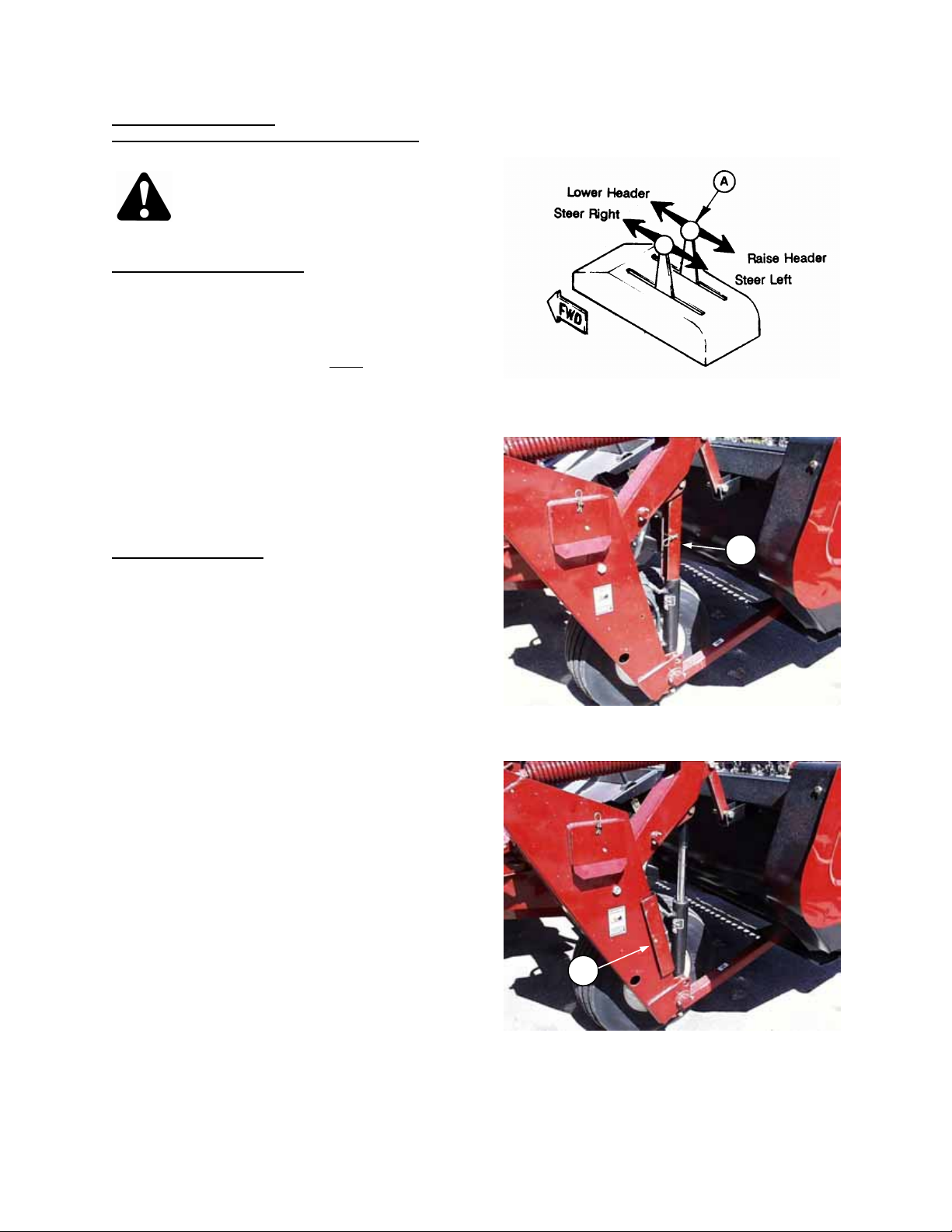
To engage cylinder stops:
1. Raise machine to maximum height by
activating remote cylinder control valve in
tractor.
NOTE: Hoses should be connected so that
moving control lever (A) back
header.
2. Remove cylinder stops from storage pos ition
and install in engaged position (B). Secure with
clevis pin and hair pin.
3. Lower machine slightly so stops take some
weight.
To lower windrower:
1. Raise machine to maximum height to take
weight off stops.
2. Remove stops from cylinders and store in
position (C). Secure with clevis pin and hair pin.
3. Lower m achine by activating remote cylinder
control valve in tractor.
raises the
TRACTOR CONTROL LEVER (TYPICAL)
B
LIFT CYLINDER STOPS - ENGAGED
C
LIFT CYLINDER STOPS - STORAGE
22
Page 23
OPERATION
STEERING
Steering the windrower is controlled by the tractor
remote hydraulic system. This steering system
allows the windrower to follow directly behind the
tractor, make a full cut to either side, or any
position in between.
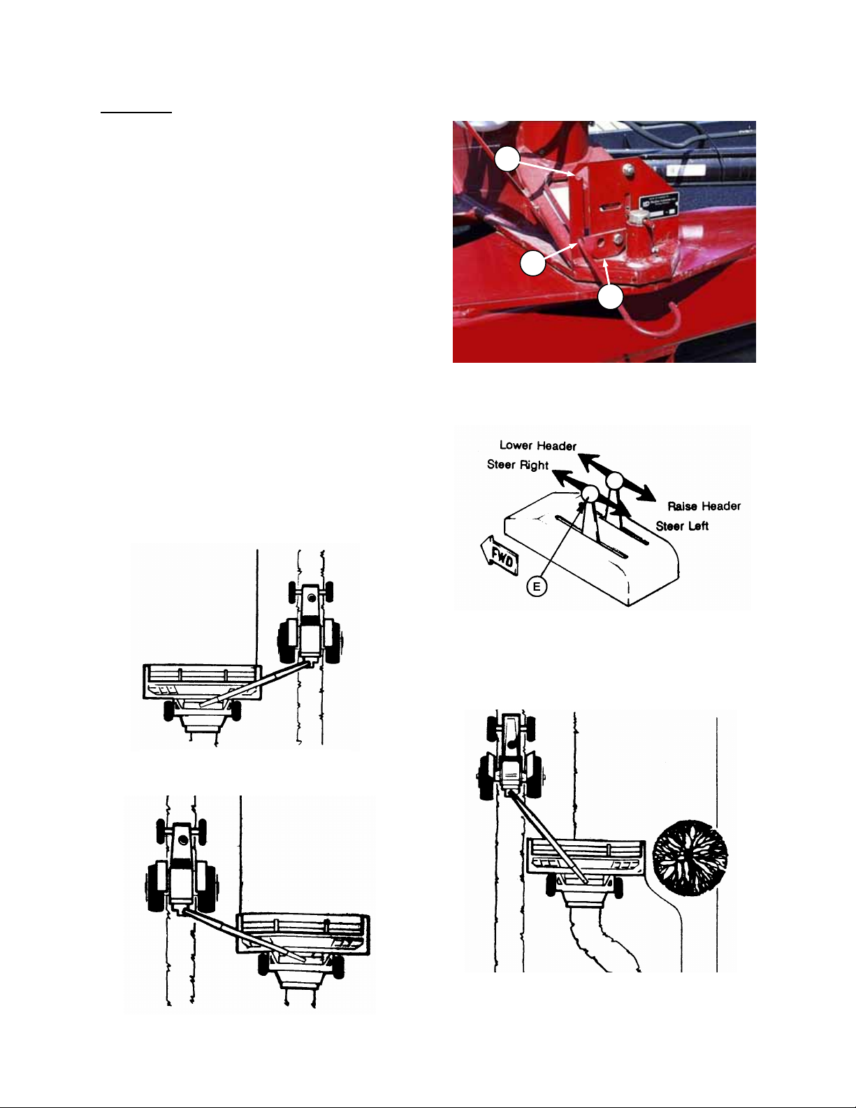
NOTE: To allow hitch to swing, latch rod must be
in field position (D). If rod is in transport position
(A), pivot rod retainer (C) up to allow moving rod
from (A) to (D).
NOTE: Hoses should be connected so that moving
tractor control lever (E) forward steers the machine
to the right and moving the lever back steer s the
windrower left.
The control is operated m omentarily for steering
and must be returned to OFF or NEUTRAL
position as soon as the windrower reaches the
desired path of travel.
The center pivot provides the operator the
opportunity to move the windrower into field
position easily, allows right angle turns in either
direction, steering around obj ects on both sides
and straight line field cutting on either side of the
tractor.
NOTE: Before steering the windrower, the header
should be raised enough that the skid shoes clear
the ground.
OPERATING ON LEFT SIDE
MOVE LATCH ROD TO FIELD POSITION (D)
TRACTOR CONTROL LEVER - TYPICAL
D
A
C
STEERING AROUND AN OBSTRUCTION
OPERATING ON RIGHT SIDE
23
Page 24
OPERATION
180q TURN
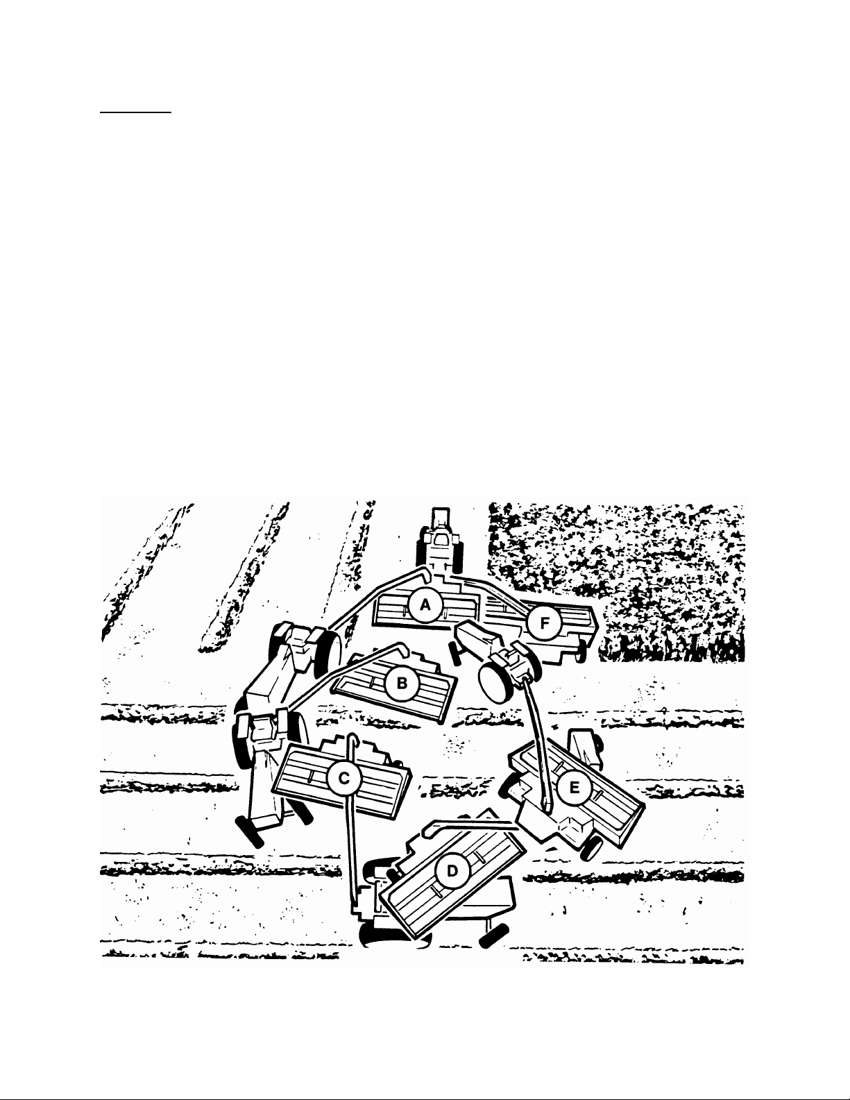
When cutting back and forth on one side of the field, approximately 50 ft. (15 m) is required at each end of the
field to make a 180
Proceed as follows:
1. Beginning at position (A), the tractor is guided away from the uncut crop while the windrower is guided
straight ahead until cutting through the end.
2. As soon as the sickle cuts through, raise the header to lift the skid shoes clear of the ground, and steer the
windrower to the extreme direction away from the uncut crop.
NOTE: For ease of operation, both lever s can be ac tivated with one hand and held until steering cylinder
completes its stroke.
3. At position (B), start turning the tractor back towards the uncut crop.
IMPORTANT: When turning, take care that the inside tractor tire does not contact tongue of windrower.
4. In positions (C) and (D), continue turning towards the uncut crop, (with the windrower steered towards the
outside of the turning circle), being aware of tongue-to-tire clearance.
5. At position (E), the tractor com pletes the cir cle and the front wheels are turned to s traddle the last cut
windrow. At this point, steer the windrower to line up with the edge of the uncut crop.
6. At position (F), lower header to cutting height and begin a new cut through the field.
° turn-around.
24
Page 25

OPERATION
TURNING SQUARE CORNERS
The following procedure is intended only as a
guide to developing a turning procedure for the
tractor being used. Specific distances are not
given due to the variances in tractor maneuverability.
1. As the tractor approaches the corner, guid e the
tractor sharply away from the crop. Steer the
windrower to maintain a straight cut ahead as
the tractor moves away from the crop.
2. As soon as the sickle cuts past where the new
corner will be, raise the header sufficiently for
skid shoes to clear the ground, then steer the
windrower to the extreme direc tion away from
the uncut crop.
3. As the tractor passes the corner, steer it
sharply back towards the uncut crop, taking
care that the inside tractor tire does not contact
the windrower tongue.
4. Guide the tractor to straddle the last cut
windrow. As the windrower finishes turning,
steer it back towards the unc ut cr op, align the
header with the crop edge and lower header to
cutting height.
OPERATING VARIABLES
Satisfactory function of the windrower in all
situations requires m ak ing pr oper adj us tments to
suit various crops and conditions.
Correct operation reduces crop loss and allows
cutting of more acres. As well, proper adjustments
and timely maintenance will increase the length of
service you receive from the machine.
The ten variables listed here and detailed on the
following pages will affect the performance of the
windrower. You will quickly become adept at
adjusting the machine to give you the desired
results.
1. Lean Bar Position
2. Ground Speed
3. Reel Speed
4. Reel Pos ition
5. Cutting Height
6. Header Angle
7. Header Flotation
8. Feed Pan / Rock Drop Tine Position
9. Roll G ap
10. Forming Shields
TURNING A SQUARE CORNER
OPERATING VARIABLES
25
Page 26

OPERATION
LEAN BAR POSITION
IMPORTANT: To prevent structural damage to the
header, do not operate with lean bar removed.
Use the lean bar adjustment to accommodate
different crop heights.
The lean bar should strike the upper portion of the
crop, leaning it away from the header and
exposing the stalks to the sickle.
To extend or retract lean bar, re-position hardw are
(A) in adjustment holes as required.
GROUND SPEED
CAUTION: Reduce speed when turning, crossing slopes, or when traveling over rough
ground.
Tractor ground speed should not exceed 8 mph (13 km/h). For most crop conditio ns a g round speed of 5 mph
(8 km/h) has been found satisfactory.
Choose a ground speed that allows the sickle to cut the crop smoothly and evenly.
The chart below indicates the relationship between ground speed and area cut for three header sizes.
Example: At ground speed of 5 mph (8 km/h) with a 14 ft. windrower, the area cut would be approximately 9
acres (3.7 hectares) per hour.
LEAN BAR ADJUSTMENT
A
26
Page 27

OPERATION
CHANGING REEL SPEED
REEL SPEED
For best feeding of the crop into the auger, reel
speed should be just faster than ground s peed.
This gently sweeps material across the sickle into
the auger.
The reel speed is fac tory set at 72 rpm . (No-load
at rated tractor RPM.)
With a pulley position exchange, other reel speeds
are possible. (See chart.) A slower reel speed will
reduce excessive crop carry-over, while a faster
reel speed will result in a more even stubble height
in down and tangled crops.
To change reel speed:
a. Loos en jam nut (C) on adjuster bolt and two
flange nuts (D) at reel drive arm. Loosen
adjuster bolt (E) to slacken belt. Remove belt.
b. Remove three flange locknuts at position (A).
c. Remove three bolts and lockwashers at
position (B).
d. Position pulleys to achieve desired reel speed,
(see chart). Replace pulley hardware.
NOTE: For 66 rpm reel speed it will be
necessary to purchase an additional 10
O.D. pulley from your Dealer.
e. Replace reel drive belt and tighten. Check reel
drive chain tension. See Maintenance /Service
section for recommended belt and chain
tension.
REEL POSITION
Reel position has been found to be a critical
position is factory set for average str aight standing crop. It c an be adjusted both vertically and horizontally
(fore-aft) for differ ent crop conditions. See the c hart below for rec omm ended reel position in unus ual crop
conditions. (Continued next page.)
9 ½" OD
Pulley Position
10 ½" OD
Pulley Position
Reel
Speed
B A 59 rpm
A B 72 rpm
none A & B
66 rpm
REEL SPEED CHART
(for positions (A) & (B) see photo below)
E
C
A
D
1/2 inch
B
66 rpm CONFIGURATION SHOWN
factor in achieving good results in adverse conditions. The reel
· Crop down or lodged Forward & down (also increase reel speed)
· Wet or dead material collects Back & down (close to guards)
on cutterbar, plugging sickle.
· Short crop. Back
· Thick stemmed or heavy standing crop. Up and forward
REEL POSITION CHART
Unusual Crop Condition Reel Position
27
Page 28

OPERATION
RIGHT SIDE
REEL POSITION
NOTE: The reel must be adjusted equally on both
sides, both horizontally and vertically.
To adjust reel horizontal (fore-aft) position:
a. Loos en jam nut (A) on adjuster bolt and two
flange nuts (B) at reel drive arm. Loosen
adjuster bolt (C) to slacken belt
b. Loosen nut (D) and back of f nut (E). T urn nut
(F) to move idler sprocket upward until reel
drive chain is loose.
c. Loosen nuts (G), three on left side, four on right
side.
d. Loosen jam nut on bolt (H), both sides, and
turn adjuster nuts to move reel f ore or aft to
desired position. Tighten jam nut.
e. Tighten nuts (G).
f. Tighten belt first, then tighten chain. See
recommended tensions in Maintenance/
Service section.
To adjust reel vertical position:
a. Loos en jam nut (A) on adjuster bolt and two
flange nuts (B) at reel drive arm. Loosen
adjuster bolt (C) to slacken belt
b. Loosen nut (D) and back of f nut (E). T urn nut
(F) to move idler sprocket upward until reel
drive chain is loose.
c. Loosen nuts (G), three on left side, four on right
side.
d. Loos en jam nuts (J) (left side only), and use
push bolts (K), two per side, to move reel up or
down to desired position. Tighten nuts (J).
e. Tighten nuts (G)
f. Tighten belt first, then tighten chain. See
recommended tensions in Maintenance/
Service section.
To adjust tine aggressiveness:
a. At right side of reel (cam end) only, loosen four
nuts (G).
b. Use push bolts (K) to rotate cam to desired
position. Viewed from right side, rotate cam
clockwise to obtain more aggressive tine
action.
c. Tighten nuts (G), then check that chain and/or
belt have not become over tight. Adjust to
recommended tension if required. See
Maintenance/ Service section.
After adjusting reel position:
a. Check that the reel rotates freely. Tines m ust
not contact auger, guards or ground.
b. Check that the reel is adjusted to the same
position on both sides. Reel tube should
appear parallel to header beam from both side
and front.
c. Check header float and adjust if required. See
"Header Flotation" in this section.
(continued)
REEL POSITION ADJUSTMENTS - RIGHT SIDE
A
B
LOOSENING REEL DRIVE BELT –
C
K
E
F
D
H
G
J
K
G
H
REEL POSITION ADJUSTMENTS - LEFT SIDE
28
Page 29

OPERATION
CUTTING HEIGHT
Control cutting height with skid plates, not with the
hydraulic cylinder. Having the header "ride" on the
skid plates allows the float linkage to float header
over obstacles and follow ground contours, rather
than supporting the header with the cylinder.
NOTE: Lowering the skid plates raises the cutting
height. This may be desirable in stony conditions,
to reduce damage to cutting components. Also, a
longer stubble length helps material dry faster.
To adjust cutting height:
WARNING: To avoid bodily injury or
death from unexpected start-up or
fall of raised machine, stop engine,
remove key and engage lift cylinder
stop before going under machine to
adjust skid plates or for any reason.
a. Remove pin (A) at each skid plate.
b. Raise or lower skid plate (B) to desired
position.
c. Replace pin (A).
After adjusting cutting height:
a. Check that skid plates are adjusted to the
same position.
b. Check header float and adjust if required. See
"Header Flotation" in this section.
NOTE: Left and right skid plates are standard
equipment. An additional two inner skid plates may
be added if required.
WARNING: Stones or other foreign
objects carried into the conditioner
rolls can be ejected with force in
ANY direction. Keep everyone
several hundred feet away fr om your
operation and be sure you are
adequately protected. See "General
Safety" in Safety section for
recommended protective wear.
A
B
CUTTING HEIGHT ADJUSTMENT
29
Page 30

OPERATION
HEADER ANGLE
Header (or guard) angle can be var ied f rom 6° to 11.5° below horizontal. Choose an angle that maximises
performance for your crop and field conditions. A flatter angle provides better clearance in stony conditions
while a steeper angle is required in down crops for better lifting action.
To adjust header angle
a. Loosen nut (A).
b. To decrease (flatten) header angle, turn nut (B) clockwise.
c. To increase (steepen) header angle, turn nut (B) counter-clockwise.
d. Tighten nut (A) to 200 ft.lbs. (270 N.m)
After adjusting header angle
a. Check cutting height and adjust if required. See "Cutting Height" in this section.
b. Check header float and adjust if required. See "Header Flotation" in this section.
NOTE: Two optional kits are available which allow
header angle to be adjusted hydraulically with a
cylinder replacing the mechanical link shown
above. One kit (B 4257) requires a separate
hydraulic circuit from the tractor. The other
(B 4256) uses the existing tongue steering cylinder
hydraulic circuit, and a remote switch-operated
selector valve controls which circuit is currently
active. Installation instruc tions are included with
the kits.
:
:
A
B
HEADER ANGLE ADJUSTMENT
OPTIONAL HYDRAULIC HEADER ANGLE KIT
30
Page 31

OPERATION
HEADER FLOTATION
Header flotation springs are normally set so 70 lbs. force (311 N) is required to lift either end of the header just
off the ground.
In rough or stony conditions, it may be desirable to change setting to 35-50 lbs. (156-222 N) to protect cutting
components.
NOTE: When f loat setting is light, it may be necessary to use a slower ground speed to avoid excessive
bouncing and leaving a ragged cut.
To increase header flotation
a. Raise header fully.
b. Back jam nut (A) away from spring.
c. Turn adjuster bolt (B) further into spring to
increase flotation.
d. Tighten jam nut (A) against spr ing insert
(C) to secure the setting.
e. Lower header and check header flotation
at each end.
IMPORTANT: Float setting (or lifting force)
must be equal on both springs. Weight
difference between left and right ends
requires differ ent spring lengths to achieve
equal float at both ends. Note that other
operating variable adjustments may affect
float setting. Check the f loat and readjust if
necessary after adjusting reel position, cutting
height, or header angle. Also, if using a
tractor with drawbar height different than 16
inches (406 mm) flotation will be affected.
Adjust as required.
FEED PAN / ROCK DROP TINE POSITION
The rear of the feed pan is adjustable up and down
to raise or lower the feed pan and rock drop tines.
• Move down in heavy crop to prevent plugging of
bulky material.
• Move up in light crop for even windrow
formation.
• To adjust, loosen hardware (D) both sides and
position rock drop tine support as required.
• Align pointer at each side of rock drop tine
support with slot to match crop condition:
Light Crop – Upper slot
Normal Crop – Center slot
Heavy Crop – Lower slot
NOTE: Use pointer to align with slot, not tines
which are aligned above the pointer as shown.
• Tighten hardware (D) both sides.
, which decreases the force required to lift header:
HEADER FLOTATION ADJUSTMENT
ROCK DROP TINE HEIGHT ADJUSTMENT
C
D
A
B
31
Page 32

OPERATION
ROLL GAP
Steel rolls "condition" the crop by crimping the
stem in several places. This allows moisture
release for quicker drying. The degree to which the
crop is conditioned as it passes through the rolls i s
controlled by roll gap (A), measured from bar to
roll tube. The gap is factory set at 3/4 inch (20
mm) for normal operation.
Correct conditioning of alfalfa, clover and other
legumes is usually indicated when 90% of the
stems show cracking, but no more than 5% of the
leaves are damaged. Use only enough roll gap to
achieve this result.
A slightly larger gap (up to 1 inch [25 mm]) may be
desirable in thick stemmed cane-type crops;
however, too large a gap may cause feeding
problems.
Grass type crops may require less gap for proper
feeding and conditioning.
To adjust roll gap
NOTE: The top face of nut (B) is used as the
indicator for the gauge decal on the threaded rod.
Each division on the roll gap decal represents a
change of approximately 1/8 inch (3mm) in roll
gap. The factory setting of 3/4 inch (20mm ) roll
gap is mark 5 on the dec al. When adjusting roll
gap, be sure that the decal reading is the same on
both sides of the conditioner roll to achieve
consistent intermesh across the rolls.
a. Raise header fully.
b. Loosen jam nut (B), both sides.
c. To increase roll gap, turn nut (C) clockwise.
d. To decrease roll gap, turn nut (C) counter-
clockwise.
e. Tighten jam nut (B), both sides.
f. Lower header and inspect roll gap along the
length of the rolls.
NOTE: Roll tension (the force holding the rolls
together) is factory set and non-adjustable.
WARNING: To avoid bodily injury or
death from unexpected start-up or fall
of raised machine; stop engine,
remove key and engage lift cylinder
stop before going under machine to
examine rolls or for any other reason.
:
A
ROLL GAP
= APPROX. 1/8” (3 mm)
ROLL GAP CHANGE
ROLL GAP DECAL
B
C
ROLL GAP ADJUSTMENT
32
Page 33

OPERATION
FORMING SHIELDS
WARNING: Keep hands and feet away from discharge opening. Keep everyone several
hundred feet away from your oper ation. Never direct the dis charge toward anyone. Stones
or other foreign objects can be ejected with force.
The position of the forming shields controls the width and placement of the windrow. The decision on forming
shield position (infinite settings between 30 and 92 inches [760 - 2346 mm]) should be based on the follow ing
factors:
- weather conditions (rain, sun, humidity, wind)
- type and yield of crop
- drying time available
- method of processing (bales, silage, "green-feed")
A wide windrow will generally dry faster and more evenly, re sultin g in l ess prot ein l oss. Fast dry ing i s especi ally
important in areas where the weather allows only a few days to cut and bale. See "Haying Tips" in this sectio n
for more information.
Where weather conditions permit or when drying is not critical, for example, when cutting for silage or "greenfeed", a narrower windrow may be preferred for ease of pick-up.
To adjust windrow width and placement
IMPORTANT:
Set forming shield side deflectors to desired width
by repositioning adjuster rods (A) in holes. To
ensure windrow placement is centered with
respect to tractor wheels, rear edge of left and
right side deflectors m ust be equal distance from
tongue center pivot, as shown on decal (E) on the
top shield. To achieve this setting, adjus ter rods
must be in the corresponding hole both sides.
Count holes from inner-most hole (B).
NOTE: If forming shield side deflectors are too
loose, or too difficult to m ove with adjuster rods:
Back off nut (D) and adjust lower nut (C) as
required. Then, holding nut (C) with a wrench,
tighten top nut (D) securely against nut (C).
Rear Deflector
The rear deflector (F ) slows the crop exiting the
conditioner rolls, direc ts the flow downward, and
"fluffs" the material.
The rear deflector can be adjusted down for more
crop control in light material, and up for clearance
in heavier crops.
To adjust rear deflector, pull up or push down one
side of deflector (F), then repeat at the other side.
There is no hardware to be loosened.
NOTE: For even windrow formation, be sure the
deflector is not twisted.
:
D
C
B
A
E
F
FORMING SHIELD ADJUSTMENTS
33
Page 34

OPERATION
HAYING TIPS
There is one certainty when making hay - a quick cure will maintain top quality. It is critical to have the cured
hay baled as quickly as possible, for two reasons:
1. Every day hay lies on the ground, 5% of the protein is lost.
2. The sooner the cut hay is off, the earlier the start for next growth.
Generally, leaving the windrow as wide and thin as possible makes for the quickest curing, however th ere ar e
other factors which affect curing time:
1. TOPSOIL MOISTURE
When the ground is wetter than the hay, moistur e f r om the soil is absorbed by the hay above it. Determine
topsoil moisture level before cutting. Use a moisture tester or estimate level:
Over 45% - WET - Soil will be muddy
25 - 45% - DAMP - Walking on soil leaves tracks
Under 25% - DRY - Soil will be dusty on top
When ground is wet due to irr igation, wait until soil moisture drops below 45%. When ground is wet due to
frequent rains, cut when weather allows and let the forage lie on wet ground until it dries to the moisture level
of the ground. At this point, the cut hay will dry no more until the ground under it dries, so consider moving the
windrow to drier ground.
On wet soil, the general rule of "wide and thin" does not apply. A narrower windrow will dry faster than hay left
flat on wet ground.
2. CLIMATE AND TOPOGRAPHY
a. Try to have as much hay cut as possible by midday, when drying conditions are best.
b. Fields sloping south get up to 100% more exposure to the sun’s heat than do north sloping fields. If you
bale and chop, consider baling the south facing fields and chopping those facing north.
c. When relative humidity is high, the evaporation rate is low and hay dries slower. If there is no wind,
saturated air becomes trapped around the win drow, furth er hindering the dry ing process. Raking or tedding
will expose the hay to fresher, less saturated air. Cutting hay perpendicular to the direction of the prevailing
winds may also help.
34
Page 35

OPERATION
HAYING TIPS
3. WINDROW CHARACTERISTICS
See "Operating Variables" in this section. Control the f ac tor s lis ted to pr oduc e a windrow with the following
characteristics:
a. High and fluffy for good air flow.
process than direct sunlight.
b. Consistent formation, not bunchy.
chopper etc.
c. Even distribution, not piled in the middle or higher on one side.
side could cause stacks to lean, round bales to have one end smaller and loose, or small square bales to
be heavy on one side, causing handling and stacking problems.
d. Properly conditioned without excessive leaf damage.
4. RUNNING TRACTOR ON PREVIOUSLY CUT WINDROW:
This can lengthen drying time by a full day in hay that will not be raked. If practical, set forming shields for a
narrower windrow that can be straddled. However, in high-yielding alfalfa, driving on the hay may be
unavoidable if a full width windrow is necessary,
5. RAKING AND TEDDING
Raking or tedding will speed up drying, however the benefits must be weighted against the additional leaf
losses which will result. W hen the ground beneath the down hay is dry, raking or tedding is probably not
worthwhile.
Big windrows on damp or wet ground should be turned over when they reach 40-50% moisture. Hay should
not be raked or tedded at less than 25% moisture, or excessive yield losses will result.
6. CHEMICAL DRYING AGENTS
Hay drying agents work by removing wax from legum e surfac es, enabling water to escape and evaporate
faster. However, treated hay lying on wet ground will also absorb ground moisture faster.
Before deciding to use a drying agent, costs and benefits relative to your area should be carefully compared.
(continued)
The movement of air through the windrow is more important to the curing
A uniform windrow permits an even flow of material into the baler,
A windrow that is higher or heavier on one
35
Page 36

OPERATION
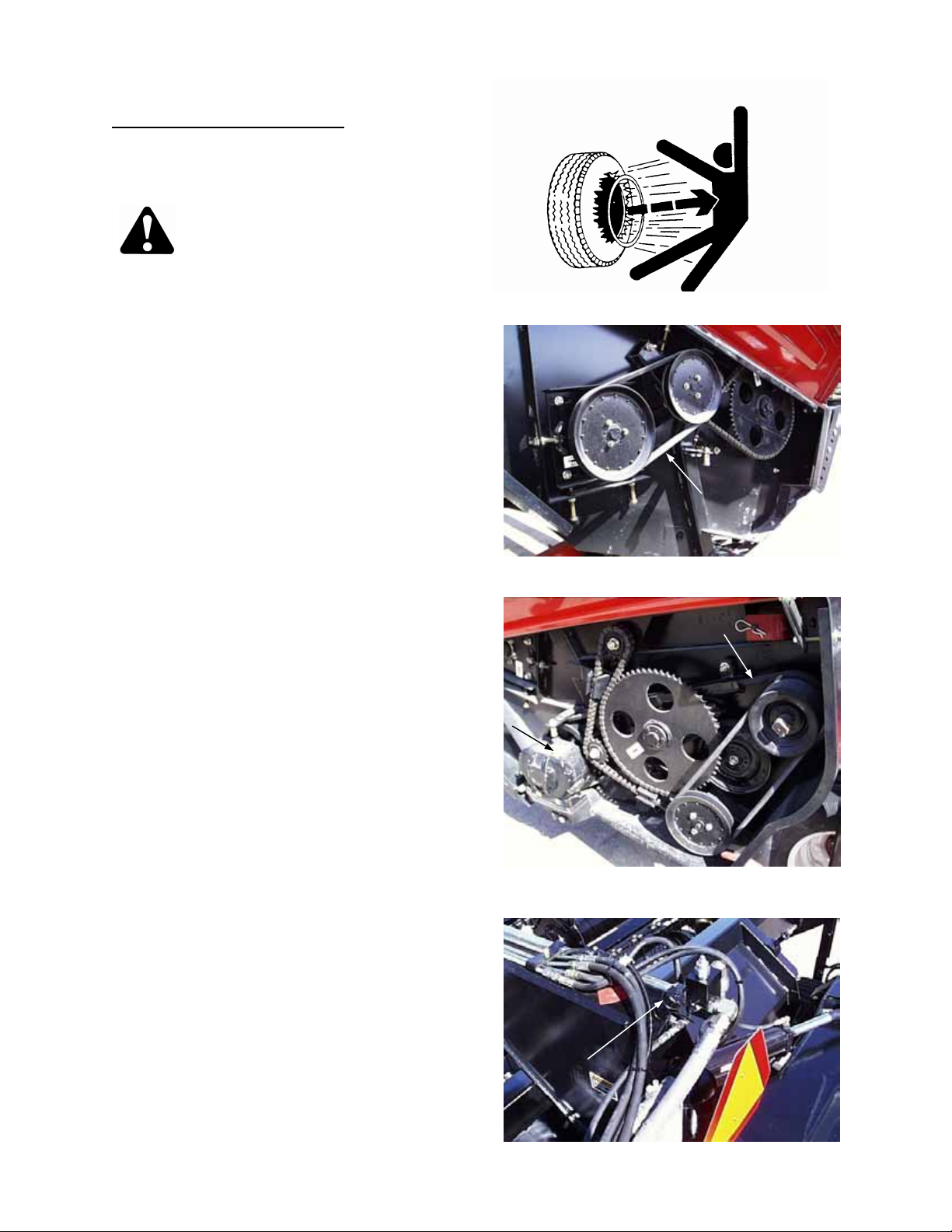
UNPLUGGING THE WINDROWER
WARNING: Stop tractor engine and remove key before removing plugged material from
windrower. A child or even a pet could engage the drive.
If the sickle plugs
1. Stop forward movement of the tractor and stop the PTO.
2. Lift the cutterbar about 12 inches (300 mm).
3. Back up about 3 feet (1 metre) while slowly engaging the PTO.
4. If the plug does not clear; raise machine, shut off engine, remove key and lock tractor brakes.
5. Engage lift cylinder stop.
WARNING: Wear heavy gloves when working around sickle.
6. Clean off cutterbar by hand.
If sickle plugging persis ts, see Trouble Shooting
section.
If the rolls plug
1. Stop forward movement of the tractor and stop
the PTO.
2. Raise the machine and slowly engage the
PTO.
NOTE: Raising the windrower automatically
reduces roll tension, to ease plug removal.
3. If plug does not clear: with machine still raised,
shut off engine, remove k ey and lock tractor
brakes.
4. Engage lift cylinder stop.
WARNING: Wear heavy gloves when
working around sickle.
5. Clean off cutterbar and area under reel by
hand.
6. Use wrench on left-hand end of prim ary drive
shaft (A) to turn rolls forward until plug clears.
NOTE: Store wrench in header fram e tube at left
end, secured with hairpin (B) as shown.
If roll plugging persists, see Trouble Shooting
section.
:
:
A
CLEARING PLUGGED ROLLS
WRENCH STORAGE
B
36
Page 37

OPERATION
SHUT-DOWN PROCEDURE
CAUTION: Before leaving the tractor
seat for any reason:
1. Park on level ground if possible.
2. Lower the windrower fully.
3. Place all controls in NEUTRAL or PARK.
4. Disengage PTO.
5. Engage the park brake.
TRANSPORTING THE WINDROWER: TOWING
WARNING: To avoid injury or death from los s of c ontrol, enga ge tr anspor t lock pin be fore
transporting machine. Use correct transport procedure as detailed:
1. The hitch steering cylinder and hoses must
be full of oil before towing the windrower. If
not previously done, fill steering circuit as
follows:
• Connect the two hitch steering cylinder
hoses to a tractor hydraulic circuit.
• Steer the header completely to the left, then
right. Repeat three or four times.
2. Place transport latch rod in transport
position (A) and engage r od retainer (C).
3. Slowly shift hitch into transport position s o
the machine is centered directly behind the
tractor. See "Steering" in this section. Hitch
will lock when it reaches center position.
Oscillate the header left and right a small
amount to ensure transport lock pin (B) is
properly engaged in the plate on carrier
frame.
WARNING: The transport lock pin
locks the machine to tow directly
behind the tractor and prevents
inadvertent movement to either
side due to accidental operation of
the remote hydraulic control levers
or to a malfunctioning hydraulic
system.
4. Raise the w indrower fully and engage lift
cylinder stop. See "Lift Cylinder Stop".
5. Do not tow with a vehicle weighing less
than 5000 lbs. (2300 kg).
6. Be sure hitch chain is properly attached to
towing vehicle. Provide only enough slack
in chain to permit turning . See "Attaching
Windrower to Tractor" in this section.
7. Be sure jack is properly attached in storage
position on frame tube.
6. Stop engine and remove key from ignition.
7. Wait for all movement to stop.
8. Lock tractor anti-vandalism covers and
closures when leaving the machine
unattended.
8. Check local laws for width regulations and
9. Keep Slow Moving Vehicle emblem,
reflectors and lights clean and visible at
rear of windrower.
10. Be aware of roadside obstructions,
oncoming traffic and bridges.
11. Travel speed should be such that complete
control and machine stability are
maintained at all times. Do no t exceed 20
mph (30 km/h). Reduce speed for corners
and slippery conditions.
12. When transporting on roads, use tractor
lights and windrower flashing amber and
red taillights to provide adequate warning
to operators of other vehicles.
13. Do not transport the windrower on a road or
highway at night, or in conditions, which
reduce visibility, such as fog or rain.
37
B
A
C
TRANSPORT LATCH ROD & LOCK
lighting or marking requirements before
transporting on roads.
Page 38

OPERATION
LOWER AND TIE DOWN UNIT
TRANSPORTING THE WINDROWER: FLATBED
CAUTION: Use the following
procedure when shipping the
windrower on a flatbed trailer.
1. Raise header with tractor hydraulics and install
lift cylinder stops.
2. Position lean bar to hang vertically downward.
Install only one bolt per side. (Remove divider
rods, if equipped.)
3. Remove complete rear forming shield group, in
whole.
4. At tongue pivot, back off two 5/8 nuts (B)
approximately 3/4 inch (20 mm ). This clears
the stop to allow pivoting the tongue past the
normal travel range.
NOTE: If tongue does not raise up as nuts (B)
are loosened, lift rear of tongue with fork lift to
clear stops.
5. Detach rod end of tongue shift cylinder from
frame and swing tongue to the right until no
part of tongue extends forward of header R/H
end panel (that is, the tongue m ust not widen
the shipping package). Secure the cylinder to
the tongue for shipping. Tie tongue to frame at
float arm (C) to prevent movement. (Use
cardboard or suitable material under the tie to
protect paint.)
CAUTION: Be sure forklifts are large
enough to lift the windrower safely.
See Specifications section for weight
of the unit.
6. Position two forklifts as shown, lift windrower
and back the flatbed trailer under the unit.
IMPORTANT: To allow windrower to rest
securely on header panels, hitch end of tongue
must extend over rear of flatbed by
approximately 2 feet (0.6 m).
7. Lower windrower onto flatbed so its weight
rests on the tires and sloped edge (D) of
header end panels.
8. Block wheels and tie the unit down securely.
NOTE: TONGUE DO E S NOT WIDEN SHIPPING
PACKAGE AND HITCH END OF TONGUE EXTENDS
APPROX. 2 FT. OVER END OF FLATBED
B
LOOSEN NUTS TO RAISE TONGUE
C
RAISE UNIT - POSITION FLATBED
C
D
38
Page 39

OPERATION
STORAGE PROCEDURE
Do the following at the end of each operating
season:
CAUTION:
1. Clean the windrower thoroughly. Neve r us e
gasoline, naphtha or any volatile material
for cleaning purposes. These materials may
be toxic and/or flammable.
2. Cover cutterbar and sickle guards to
prevent injury from accidental contact.
Also:
3. Store in a dry, protected place if possible. If
stored outside, always cover windrower with a
waterproof canvas or other protective material.
4. Raise header and engage lift cylinder stops.
5. If possible, block up the windrower to take
weight off tires.
6. Repaint all worn or chipped painted surfaces to
prevent rust.
7. Loosen drive belts.
8. Lubricate the windrower thoroughly, leaving
excess grease on fittings to keep moisture out
of bearings. Apply grease to exposed threads,
cylinder rods and sliding surfaces of
components. Oil sickle components to prevent
rust.
9. Check for worn components and repair.
10. Check for broken components and order
replacement from your dealer. Attention to
these items right away will save time and effort
at beginning of next season.
11. Replace or tighten any missing or loose
hardware. See Specifications section for torque
charts.
12. Remove divider rods (if equipped) to reduce
space required for inside storage.
MAINTENANCE/SERVICE
SERVICE PROCEDURES
CAUTION: To avoid personal injury,
before servicing windrower or
opening drive covers:
1. Fully lower the windro wer. If necessary to
service in the raised position, always
engage lift cylinder stops.
2. Disengage PTO.
3. Stop engine and remove key.
4. Engage park brake.
5. Wait for all
Park on level surface when possible. Block
wheels securely if w ind rower is p arked on an
incline. Follow all recommendations in your
Tractor Operator’s Manual.
Wear close-fitting clothing and cover long hair.
Never wear dangling items such as scarves or
bracelets.
Wear protective shoes with slip-resistant
soles, a hard hat, protective glasses or
goggles and heavy gloves.
Be prepared if an accident should occur. Know
where the first aid kit and fire extinguishers a re
located and how to use them.
Keep the service area clean and dry. Wet or
oily floors are slippery. Wet spots can be
dangerous when working with electrical
equipment. Be sure all electrical outlets and
tools are properly grounded.
Use adequate light for the job at hand.
Replace all shields removed or opened for
service.
Use only service and repair parts made or
approved by the equipment manufacturer.
Substituted parts may not meet strength,
design or safety requirements.
Keep the machine clean. Never use gasoline,
naphtha or any volatile material for cleaning
purposes. These materials may be t oxic and /or
flammable.
moving parts to stop.
39
Page 40

MAINTENANCE/SERVICE
TIGHTEN COLLAR IN DIRECTION
RECOMMENDED FLUIDS AND LUBRICANTS
GREASE
Use an SAE Multi-Purpose High Temperature Grease with Extreme Pressure (EP) Performance and
containing at least 1.5% molybdenum disulphide. (NLGI Grade 2)
Also acceptable is an SAE Multi-Purpose Lithium Base Grease.
HYDRAULIC OIL
Use SAE 15W40 complying with SAE specs for API Class SJ and CH-4 engine oil.
WOBBLE BOX LUBRICANT
In sickle drive wobble box, use SAE 85W-140 gear lubricant (API Service Classification GL-5)
ROLL DRIVE CHAIN CASE
See "Grease", above.
CAPACITIES
Wobble Box (Sickle Drive) - 2.2 litres (2.3 U.S. quarts)
Roll Drive Chain Case - 2000 grams (5 tubes)
Hydraulic Reservoir - 12 ft. windrower
14 ft. windrower
16 ft. windrower
STORING LUBRICANTS
Your machine can operate at top efficiency only if clean lubrican ts are used. Use clean containers to handle all
lubricants. Store them in an area protected from dust, moisture, and other contaminants.
SEALED BEARING INSTALLATION
1. Clean shaft and coat with rust preventative.
2. Install flangette, bearing, second flangette and
lock collar.
NOTE: The locking cam is only on one side of
the bearing.
3. Install (but do not tighten) the flangette bolts.
4. W hen the shaft is correctly located, lock the
lock collar with a punch. The c ollar should be
locked in the sam e dir ect ion the shaf t r otates .
Tighten the set screw in the collar.
5. Tighten the flangette bolts.
6. Loosen the flangette bolts on the mating
bearing one turn and re-tighten. This will allow
the bearing to line up.
: 93 litres (25 U.S. gallons)
: 104 litres (27 U.S. gallons)
: 126 litres (33 U.S. gallons)
SHAFT ROTATES
40
Page 41

MAINTENANCE/SERVICE
DRIVE SHIELDS
Press a screwdriver against latch in opening at (A )
to open the left and right drive shields on the
header.
CAUTION: Ensure shield lock
engages in the open position as
shown at (B) before letting go of
shield.
To close, push shield slightly
farther open and move loc k
out of engagement slot.
Lower shield by hand and
release about 12” from fully
closed position. Shield will
self-latch.
GREASING THE WINDROWER
See "Recommended Lubricants" in this secti on for
recommended greases.
The following greasing points are m arked on the
machine by decals showing a grease gun (A), and
grease interval (B) in hours of operation. Log your
hours of operation and use the "Maintenance
Checklist" provided to keep a record of scheduled
maintenance.
Procedure:
1. Wipe grease fitting with a clean cloth before greasing, to avoid injecting dirt and grit.
2. Inject grease through fitting with grease gun until grease overflows fitting, except where noted.
3. Leave excess grease on fitting to keep out dirt.
4. Replace any loose or broken fittings immediately.
5. If fitting will not take grease, r emove and clean thoroughly. Also clean lubricant passageway. Replace
fitting if necessary.
10 Hours or Daily
1. Upper Roll Universal Shaft (C) - three fittings
2. Lower Roll Universal Shaft (D) - three fittings
D
C
B
MAIN DRIVE SHIELDS
25 Hours
1. Sickle Head (E) - one fitting
NOTE: To prevent binding and/or excessive wear
caused by sickle pressing on guards, do not over
grease. If m ore than 6 to 8 pum ps of the grease
gun are required to fill the cavity, replace the seal
in the sickle head. When changing seal, check pin
and needle bearing for wear. R eplace i f necessary .
See page
SAMPLE GREASE DECAL
48.
E
A
ROLL UNIVERSALS
41
SICKLE HEAD
Page 42

MAINTENANCE/SERVICE
LEFT SIDE
RIGHT SIDE
ROLL SHAFT BEARINGS
C
(continued)
B
F
4. Roll Shaft Bearings (G) & (H) - four fittings
H
REEL AND AUGER BEARINGS - RIGHT SIDE
GREASING THE WINDROWER
50 Hours
:
1. Main Drive Shaft Bearings (A) & (B)
- two fittings
A
MAIN DRIVE SHAFT BEARINGS
2. Reel Shaft Bearings (C) & (D) - two fittings
REEL SHAFT BEARING - LEFT SIDE
3. Auger Shaft Bearings (E) & (F) - two fittings
G
E
D
AUGER SHAFT BEARING - LEFT SIDE
42
Page 43

MAINTENANCE/SERVICE
LOWER FLOAT LINK BUSHINGS
GREASING THE WINDROWER
50 Hours:
(continued)
5. Frame-to-Header Pivot (J) - two fittings
J
FRAME-TO-HEADER PIVOT
6. Lower Float Link Bushings (K) - two fittings
7. Tongue Pivot (L) - one fitting
8. Transport Lock Pin (M) - one fitting
TONGUE PIVOT & TRANSPORT LOCK PIN
9. Auger Drive Jackshaft Bearings (N)
- one fitting (on sprocket hub)
M
L
K
N
AUGER DRIVE JACKSHAFT BEARINGS
43
Page 44

MAINTENANCE/SERVICE
WHEEL HUB BEARINGS
GREASING THE WINDROWER
100 Hours:
1. Wheel Hub Bearings (D) - two fittings
CENTER LINK BALL JOINTS
Apply SAE 30 or equivalent lightweight oil to the
center link ball joints (A) every 50 hours
A
(continued)
.
HITCH PIN LOCK NUT
Check hitch pin nut (C) every 50 hours.
350 ft. lbs. (475 N
CHECK HITCH PIN LOCK NUT
D
Maintain
⋅m) torque.
C
OIL CENTER LINK BALL JOINTS
SPRING PIVOTS
Apply SAE 30 or equivalent lightweight oil to the
spring pivots (B) every 50 hours.
B
OIL SPRING PIVOTS
44
Page 45

MAINTENANCE/SERVICE
HYDRAULICS
The windrower is hydraulically powered using:
1. A s elf-contained hydraulic system to operate
the header functions.
2. The tractor remote system to operate the
header lift cylinder and steering cylinder.
Hydraulic Hoses and Lines
Check hydraulic hoses and lines daily
leaks.
Relieve pressure before disconnecting
hydraulic lines. Tighten all connections b efor e
applying pressure. Keep hands and body away
from pin- holes and nozzles which eject fluids
under high pressure. Use a piece of cardboard
or paper to search for leaks. If ANY fluid is
injected into the skin, it must be surgically
removed within a few hours by a doctor
familiar with this type of injury or gangrene
may result.
IMPORTANT: Keep hydraulic coupler tips and
connectors clean. Dust, dirt, water and foreign
material are the major causes of hydraulic system
damage. DO NOT attempt to service hydraulic
system in the field. Precision f its require W HITE
ROOM CARE during overhaul.
Hydraulic Reservoir
The windrower’s self-contained hydraulic system
uses the tongue of the machine f or the hydraulic
oil reservoir. See “Recommended Fluids and
Lubricants” on page 40 for proper oil type and
capacity.
Check oil level daily
(A) at rear of tongue. Oil level should be between
ADD and FULL mark s on the dipstick when top
surface (C) of tongue is level and oil is cold.
removing dipstick (A), unscrew it slowly to
vent the build-up of air pressure in the
reservoir.
To add hydraulic oil:
1. Loosen hydraulic fitting (B) to vent reservoir,
making adding oil easier.
2. Slowly unscrew dipstick (A) from filler tube.
3. Add oil until level is between ADD and FULL
marks on dipstick (A). (See page 40 for oil
specs).
4. Replace dipstick and tighten fitting (B).
for signs of
WARNING: Avoid high-pressure
fluids. Escaping fluid can penetrate
the skin causing serious injury.
(before start-up) at dipstic k
WARNING: To avoid injury from
contact with hot oil, do not remove
dipstick when system is hot. When
AVOID HIGH-PRESSURE FLUIDS
SEARCH PROPERLY FOR LEAKS
HYDRAULIC RESERVOIR
C
A
B
45
Page 46

MAINTENANCE/SERVICE
OIL FILTER & RELIEF VALVE
Pump & Gearbox Matching
– Pump (P) and
gearbox (G) must be properly matched for 540 or
rpm. If problems arise related to RPM (sickle
plugging, vibration etc.), check that components
Model numbers are stamped on the pump
HYDRAULICS: Hydraulic Reservoir
Change hydraulic oil every 600 hours or 3 years
To drain the reservoir:
1. Loosen hydraulic fitting and remove dipstick as
described under "To add hydraulic oil",
previous page.
2. Disconnect the pump supply hose (A) from the
pump.
NOTE: A drain pan with a capacity of 130 litres
(35 U.S. gallons) will be required.
Hydraulic Oil Filter
Change hydraulic oil filter (B) after the first 100
hours operation and every 250 hours thereafter.
To change:
1. Clean around the filter head.
2. Remove the filter and clean the gasket surface
of the filter head.
3. Apply a thin film of clean oil to the gask et on
the new filter.
4. Install new filter. Turn the filter onto the mount
until the gasket contacts the filter head. Tighten
the filter an additional 1/2 to 3/4 turn by hand.
IMPORTANT: Do not use a filter wrench to install
the filter. Over-tightening can damage gasket and
filter.
Hydraulic Relief Pressure
A possible cause of poor cutting performance
and/or excessive heating of hydraulic oil is low
relief pressur e. Relief valve (D) is factory set at
4000 psi (27.6 MPa). See your dealer for
adjustment or s ervice. A pressure gauge can be
installed at tapped elbow (C).
ELECTRICAL
Use electrical tape and wire clips as required to
prevent wires from dragging or rubbing.
Keep lights clean and replace burnt bulbs.
To replace light bulbs
:
1. Using a phillips screwdriv er, remove screws (B )
from fixture, freeing amber cover.
2. Replace bulb, plastic lens, and reinstall screws.
NOTE: Bulb trade #1156.
Wiring Harness:
White - ground Yellow - L/H amber
Brown - red tail light Green - R/H amber
(continued)
.
1000
are matched as follows:
540 RPM: Pump 73428 LA_ with Box 77020_ _
1000 RPM: Pump 73424 LA_ with Box 77030_ _
mounting flange and the gearbox front plate.
G
• ENSURE RPM MATCH AT PUMP/GEARBOX
• DRAIN RESERVOIR AT PUMP SUPPLY HOSE
B
A
P
D
C
B
REPLACING LIGHT BULBS
46
Page 47

MAINTENANCE/SERVICE
OIL KNIFE DAILY EXCEPT IN SANDY SOIL
SICKLE AND SICKLE DRIVE
WARNING: Keep hands clear of the
area between guards and sickle at all
times.
CAUTION: Wear heavy gloves when
working around or handling sickles.
Sickle Lubrication
Apply SAE 10 or equivalent light weight oil daily
(one or two drops per section) along entire length
of sickle.
NOTE: Do not oil sickle if operating in sandy
conditions. Oil will cause sand to adhere to sickle
components, resulting in excessive wear.
Sickle Sections
Check daily
sickle back and are not worn or broken. Replace
as required.
To replace sickle section:
1. A worn or broken sickle section (C) can be
replaced without removing sickle from
cutterbar.
2. Remove lock nuts and lift section off of bolts.
IMPORTANT: Do not mix heavy and light
sickle sections o n same sickle.
3. Clean any dirt off of sic kle back and position
new sickle section on bolts. Secur e with locknuts.
To Remove Sickle
1. Clean area around sickle head. Stroke sickle to
its outer limit and remove bolt (A).
2. Insert screwdriver in slot (B) and pry up on
sickle head pin to free sickle.
3. Pull sickle out.
4. Cover sickle head to shield bear ing from dirt.
that sections are firm ly bolted to the
WARNING: Always stand to rear of
sickle during removal to reduce risk
of injury from cutting edges. Wear
heavy gloves when handling sickle.
KEEP HANDS AWAY FROM SICKLE
C
BOLT-ON SECTIONS
47
B
REMOVING SICKLE
A
Page 48

MAINTENANCE/SERVICE
SICKLE AND SICKLE DRIVE
(continued)
Sickle Head Needle Bearing Installation
Using a flat-ended tool (A) with approximately the
same diam eter as the bearing, push the bearing
into the sickle head until the top of the bearing is
flush with the step (B) in sickle head.
IMPORTANT: O-ring and plug must be in place in
sickle head before installing bearing. Assemble the
bearing with the stamped end (the end with
identification markings) against the tool.
Install seal (C) in top of sickle head with lip facing
outwards.
IMPORTANT: To avoid premature sickle head or
wobble box failure, be sure there is no looseness
in:
a) Fit of sickle head pin and needle bearing.
b) Fit of sickle head pin and pitman arm.
To Install Sickle
WARNING: Always stand to rear an d
grasp rear edge of sickle during
installation to reduce risk of injury
from cutting edges. Wear heavy
gloves when handling sickle.
IMPORTANT: Always align guards and re-set
sickle hold-downs while replacing sickle.
1. Slide sickle into plac e, install sickle head pin
and replace bolt (D). To ease assembly,
remove lube fitting from pin. Replace when
installation is complete.
NOTE: Bottom of groove in sickle head pin
must be flush with top face (E) of pitman arm.
2. Tighten bolt (D) to 160 ft.lbs. (220 N.m).
Spare Sickle Storage
A spare sickle (F) may be stored in header frame
tube at left end, as shown below. Ensure guard
tool/wrench (G) and hairpin are in place as shown
to secure the spare sickle.
G
F
NEEDLE BEARING INSTALLATION
D
A
C
B
D
INSTALLING SICKLE
E
INSTALLING SICKLE – FRONT VIEW
48
Page 49

MAINTENANCE/SERVICE
SICKLE AND SICKLE DRIVE
Guards
Check daily
proper shear cut between sickle section and
guard. Sickle sections should contact shear
surface of each guard.
Align guards with guard straighte ning tool provi ded
as shown:
To bend guard tips up, position tool as s hown at
(A) and pull up.
To bend tips down, position tool as at (B) and push
down.
NOTE: Tool is stored in header frame tube at left
end. See (G) in photo on page 48 (bottom left).
TIP: If trouble is encountered cutting tangled, but
easy to cut material (canola, peas, grain) r eplace
guards with stub guards or install a sic kle holddown on every guard. If material is tough to cut,
install stub guards with top guard and adjuster
plate. A stub guard conversion kit for the
Windrower is available from your dealer.
Excessive Breakage
Excessive breakage of sickle sections and guards can be controlled by several factors. See "Cutting Height",
"Header Angle" and "Header Flotation" in Operation section for recommendations.
Sickle Hold-Downs
Check daily
prevent sickle s ections from lifting of f guards but
still permit sickle to slide without binding. Set holddowns after guards are aligned.
To set hold-downs:
1. Use the unplug wrench (A) with the flattened
2. After adjusting all hold-downs, run header at a
that guards are aligned to obtain
that sickle hold-downs are set to
end against the front edge of hold down. Str ike
wrench with a hammer. This allows
adjustment of hold-down arch (B) without
"pinching" sickle. Clearance from hold-down to
sickle section should be .020 inch (0.5 mm).
low engine speed and listen for noise due to
insufficient clearance. Re-adjust as necessary
by placing a .020 inch (0.5 mm) shim between
hold-down and section, then striking the holddown arch (B) with a hammer.
(continued)
A
BENDING GUARD TIPS UP
B
BENDING GUARD TIPS DOWN
B
A
SETTING SICKLE HOLD-DOWNS
49
Page 50

MAINTENANCE/SERVICE
SICKLE AND SICKLE DRIVE
Sickle Drive Belt Tension
IMPORTANT: To prolong belt and drive life, do not
over-tighten belt.
To adjust:
1. Loosen nut (A) securing idler pulley.
2. Using a punch or s cr ewdriver in pry holes (B),
raise idler until a force of 12 lbs. (55 N) deflects
belt 1/2 inch (13 mm) at mid-span.
3. Tighten nut (A).
4. Re- adjust tension of a new belt after a short
run-in period, (about 5 hours).
Sickle Drive Belt Replacement
To remove belt:
1. Loosen chain idler sprocket (C) and remove
chain from drive sprocket behind pulley (D).
2. Loosen and remove auger drive belt as fol lows:
• Loosen nuts (E).
• Back off nut (F) and back bolt out of adjuster
bracket until belt can be removed. (Access bolt
head under end panel.)
3. Loosen sickle drive belt idler pulley (A).
4. Remove belt from sickle drive pulley.
5. Remove bolt-in plate in left end sheet at wobble
box (G), and route belt through this hole.
When installing new belt, never
pry belt over pulley. Be sure
idler is fully loosened, then
tension belt as above.
(continued)
B
SICKLE DRIVE BELT TENSION ADJUST.
G
A
C
A
D
E
F
SICKLE DRIVE BELT REMOVAL
50
Page 51

MAINTENANCE/SERVICE
WOBBLE BOX MOUNTING
BOLTS
SICKLE AND SICKLE DRIVE
Wobble Box Maintenance
Mounting Bolts - Check four wobble box
mounting bolts (B) torque after the first 10 hours
operation and every 100 hours thereafter. Torque
should be 200 ft.lbs. (270 N
start with the side mounting bolts.
Lubricant - Check wobble box lubricant level
before first operation and every 100 hours
thereafter. To check:
1. Raise header to a point where the wobble box
base is approximately level.
2. Remove breather/dipstick ( A). Oil level must
be between end of dipstick and bottom hole (or
groove) in dipstick.
3. Add as requir ed. See "Recommended Lubricants" for specified gear lube and capacity of
box.
4. Replace breather/dipstick.
Change wobble box lubricant after the first 50
hours operation and every 1000 hours (or 3 year s)
thereafter.
To drain wobble box, raise header fully and
engage header lift cylinder stops. Remove
breather/dipstick (A) and drain plug (D).
Assembly/Disassembly
If removing wobble box pulley, a 3-jaw puller is
recommended.
When reinstalling drive arm or pulley:
1. Remove any rust or paint from inner spline. For
replacement parts, remove oil/grease with
degreasing agent.
2. Before assembly, apply Loctite® #243 adhesive
(or equivalent) to spline. Apply in two bands (C)
as shown, with one band at end of spline and
one band approximately mid-way.
(continued)
⋅m). When tightening,
USE ADHESIVE FOR ASSEMBLY
A
D
B
& LUBRICANT
51
Page 52

MAINTENANCE/SERVICE
REEL AND REEL DRIVE
Reel Drive Chain Lubrication
Lubricate chain daily
Apply oil to upper edge of lower chain span (A).
Reel Drive Belt Tension
IMPORTANT: T o prolong drive life, do not over -
tighten belt. Belt slippage is used to protect the
reel in an overload situation.
To adjust reel drive belt tension:
1. Loos en jam nut (A) on adjuster bolt and two
flange nuts (B) at reel drive arm.
2. To tighten belt, tighten adjus ter bolt (C) until a
force of:
NEW BELT - 20 lbs. (80 N)
USED BELT - 12 lbs. (55 N)
deflects belt 1/4 in. (6 mm) at mid-span (F).
3. Tighten jam nut (A) and two flange nuts (B).
4. Re-adjust tension of a new belt after about 5
hours of operation to used belt specifications.
5. Check reel drive chain tension and adjust if
necessary. See below.
Reel Drive Chain Tension
NOTE: For major adjustments, like after
repositioning reel or auger, adjust belt tension
before
chain tension.
To adjust reel drive chain tension:
1. Loosen nut (D) and back off nut (E).
2. To increase tension, turn nut (F) to move idler
sprocket downward until total chain slac k at
(G) is 1/2 in. (13 mm).
3. Tighten nuts (D) and (E).
Reel Tines
Keep reel tines in good condition. Straighten or
replace as required.
with a light weight oil (SAE 30).
OIL REEL DRIVE CHAIN
C
REEL DRIVE BELT TENSION ADJUSTMENT
E
F
REEL DRIVE CHAIN ADJUSTMENT
52
A
A
B
F
D
G
Page 53

MAINTENANCE/SERVICE
AUGER AND AUGER DRIVE
Auger Position
The auger position has been factory set and
should not normally require adjustment. For nearly
all conditions, the auger performs best when set
as close as poss ible to the stripper bars without
rubbing. This is espec ially important in gr as s and
other crops which have a tendency to wrap.
Component wear may cause clearances to
become excessive, r esulting in feeding problem s
and uneven windrows.
NOTE: In heavier crops it may be necessary to
remove the front stripper for smoother crop flow
across the auger.
Should adjustment be required:
1. Loosen nut (A), lef t s ide, sec uring auger drive
chain idler sprocket.
2. Loosen reel drive belt and chain. See page 52
for adjustment details
3. Loosen bolts (B), four per side.
4. To adjust auger fore-aft
a. Loosen jam nut on bolt (C), both sides.
b. Turn adjuster nuts to move auger fore or aft to
desired position.
c. Tighten jam nut on bolt (C).
5. To adjust auger vertical position:
a. Loosen jam nuts (D), two per side.
b. Turn push bolts ( E), two per side, to lower or
raise auger.
c. Tighten jam nuts (D).
NOTE: The auger should clear the stripper bars on the
auger pan by approximately 1/32” – 5/32” (1 - 4 mm).
A
:
C
AUGER POSITION ADJUSTMENTS
See next page for stripper adjustment.
6. Tighten bolts (B) to secure the position.
7. Adjust tension of auger drive chain, reel drive
belt, and reel drive chain. Tighten hardware.
B
D
E
53
Page 54

MAINTENANCE/SERVICE
AUGER AND AUGER DRIVE
Stripper Bars
To adjust:
1. Position auger for clearance to strippers (A)
and (B), as shown. Use shims as required at
stripper bars (A) and (B). See Parts Catalog.
2. Loosen bolts (H) along upper stripper bar.
3. Slide extension bars (J) in or out to obtain
approximately 1/32 – 5/32” (1 – 4 mm)
clearance to auger flighting (K) along entire
auger length.
4. Tighten bolts (H).
NOTE: In heavier crops it may be necessary to
remove the front stripper (A) for smoother crop
flow across the auger.
H
J
K
B
1 – 4 mm
(1/32 – 5/32”)
CLEARANCE
1 – 4 mm
(1/32 – 5/32”)
CLEARANCE
A
STRIPPER BAR ADJUSTMENT
54
Page 55

MAINTENANCE/SERVICE
AUGER DRIVE CHAIN
AUGER DRIVE BELT
AUGER AND AUGER DRIVE
(continued)
Auger Drive Chain Lubrication
Lubricate auger drive chain daily
oil (SAE 30).
Auger Drive Chain Tension
To tighten auger drive chain:
with lightweight
K
L
M
1. Loosen idler sprocket mounting bolt (K).
2. Using a punch or scr ewdriver in pry holes (L),
move sprocket upward until deflection at (M) is
1/4 inch (6 mm).
3. Tighten bolt (K).
Auger Drive Belt Tension
IMPORTANT: T o prolong drive life, do not over -
tighten belt. Belt slippage is used to protect the
auger in an overload situation.
NOTE: Minor belt tension adjustments may be
made without affecting chain tension. F or major
adjustments, like after repositioning reel or auger,
adjust chain tension before
belt tension.
To adjust auger drive belt tension:
1. Loosen nuts (P) at auger drive arm.
2. Back off jam nut (R), then turn adjuster bolt
(access under end panel) until a force of:
NEW BELT - 20 lbs. (80 N)
USED BELT - 12 lbs. (55 N)
deflects belt 1/4 in. (6 mm) at mid-span.
3. Tighten jam nut (R) against frame t o secure the
position, then tighten nuts (P).
TENSION ADJUSTMENT
4. Re-adjust tension of a new belt after about 5
hours of operation to used belt specifications.
P
R
TENSION ADJUSTMENT
55
Page 56

MAINTENANCE/SERVICE
ROLLS AND ROLL DRIVE
Roll Drive Chain Tension
Check chain tension after the first 10 hours
operation and every 100 hours or annually
thereafter, as follows:
1. Remove rubber plug at left side of chain case.
(See "Roll Drive Chain Case Lubricant" bel ow.)
2. Chain s hould deflect a maximum 1/4 inc h (6
mm) each way.
3. If adjustment is required:
a. Loosen nut (B).
b. Loosen two bolts (C).
c. To tighten chain, rotate cam clockwise,
using a 15/16 wrench on welded nut (D).
(To loosen chain, rotate cam counterclockwise.)
d. Tighten nut (B) and bolts (C).
4. Check chain deflection as in step 2, and
replace plug (A).
Roll Drive Chain Case Lubricant
Check chain lubrication after the first 10 hours
operation and every 100 hours or annually
thereafter, as follows:
1. Remove rubber plug (A) from chain case.
2. Chain should be coated with grease.
3. If required, add one complete tube (400 g) of
SAE Multi-Purpose (EP) Lithium Base Grease
(NLGI Grade 2) to the chain case. Case
capacity is 2000 grams (5 tubes).
4. Replace plug (A).
D
C
CHAIN TENSION ADJUSTMENT
CHECK CHAIN CASE LUBE LEVEL
B
A
56
Page 57

MAINTENANCE/SERVICE
ROLLS AND ROLL DRIVE
Roll Timing
For proper conditioning, the rolls must be timed
with each steel bar on one roll centered between
two bars of the other roll as shown.
Examine roll tim ing along the length of the rolls
and adjust to desired position as follows:
1. Adjust roll drive chain tension (previous page).
2. Loosen two bolts (A) in slots
either upper or lower roll universal shaft.
3. Remove bolt (B) from one of the series of holes
in yoke plate.
4. Turn rolls to achieve best timing.
5. When roll timing is satisfactory, align any o f the
holes in yoke plate with a hole in mating plate
at drive case and install and tighten bolt (B).
Tighten bolts (A) to secure the position.
NOTE: This adjustment should be made in
conjunction with the "Roll Gap" adjustment,
detailed in Operation section.
WARNING: To avoid bodily injury or
death from unexpected start-up or
fall of raised machine; stop engin e,
remove key and engage lift cylinder
stops before going under machine to
examine roll timing, or for any
reason.
(continued)
of yoke plate on
A
ROLL TIMING
A
B
ROLL TIMING ADJUSTMENT
57
Page 58

MAINTENANCE/SERVICE
ROLLS AND ROLL DRIVE
Roll Drive Chain Removal
1. Raise header. Stop engine, rem ove key and
engage lift cylinder stops.
2. Remove bolts securing upper cover (A) to
chain case. Loosen clamp bolt (B) and slide the
cover down the drive shaft shield.
3. Remove bolts securing lower cover (C) and
remove cover.
4. Loosen two bolts (D) and nut (L) at chain
tensioner.
5. Rotate tensioner cam counter-clockwise , usin g
a 15/16 wrench on welded nut (E).
6. Remove the chain tensioner sprocket from
inside chain case.
NOTE: Be careful not to lose the three washers
between the sprocket and inner cam disc.
7. Rotate upper or lower roll universal joint to
position chain connector link (F) as shown.
8. Remove connector link (F).
9. Turn lower roll u-joint to r otate lower sprocket
(G) counter-clockwise until chain is free of the
lower sprocket.
10. Lift excess chain up and bring it out of the
chain case through the top opening.
11. Turn sickle drive pulley at left end of header to
rotate driver sprocket (H) clockwise until chain
is free of driver sprocket.
(continued)
D
RELEASE CHAIN TENSION
B
A
C
REMOVE COVERS
E
D
L
REMOVE CHAIN
58
Page 59

MAINTENANCE/SERVICE
CONNECT CHAIN AND
ROLLS AND ROLL DRIVE
Roll Drive Chain Installation
IMPORTANT: To ensure proper chain quality,
service with original equipment part only.
1. Feed the chain into chain case.
2. Lift chain up to driver sprocket (H) and engage
on first few teeth.
3. Turn sickle drive pulley at left end of header to
rotate driver sprock et counter-clockwise until
chain engages upper roll sprocket (J) as
shown.
4. Turn upper roll u-joint to rotate upper sprocket
(J) clockwise until chain engages lower roll
sprocket (G) as shown.
5. Turn the lower roll u-joint to rotate lower
sprocket (G ) counter-clockwise while holding
the first link of the c hain against s pr ocket (G).
Continue turning until chain is engaged
sufficiently to install connector link.
6. Install connector link (F ) and install the chain
tensioner sprocket (K).
7. Tension c hain as desc ribed on page 56, "Roll
Drive Chain Tension".
8. Scrape old silicone off of chain case and
covers, and clean these surfaces with solvent.
9. Apply new silicone to mating surfaces of chain
case, upper and lower covers, and drive shaf t
shield.
10. Bolt covers to chain case and tighten bolt which
clamps upper cover to drive shaft shield.
11. Replace chain case grease to capacity shown
on page 56, "Roll Drive Chain Case Lubricant".
(continued)
ENGAGE DRIVER AND UPPER SPROCKETS
ENGAGE LOWER SPROCKET
INSTALL TENSIONER SPROCKET
59
Page 60

MAINTENANCE/SERVICE
WHEELS AND TIRES
Wheel Bolts
Check and tighten wheel bolts after the first 1 hour
operation and every 100 hours thereafter.
Whenever a wheel is rem oved and re-installed,
check torque after one hour of operation. Maintain
120 ft. lbs. (160 N.m) torque.
Follow proper bolt tightening sequence shown. Be
sure valve stem (A) points away from wheel
support.
CAUTION: When installing wheel be
sure to use the holes that are
countersunk to match bolt head
profile. The second set of "straightthrough" holes do not seat the bolts
correctly.
Wheel Removal
1. Raise header fully and engage lift
cylinder stops.
2. Position 5000 lb. capacity jack on mount
provided on frame leg and raise tire just
off the ground. Place block under frame
leg at (A).
3. Remove wheel bolts
4. NOTE: To remove either wheel on 12
foot windrower, or left wheel on 14 and
16 foot windrower – Remove spindle
retaining bolt (B) and slide spindle
outboard until clearance to vertical float
spring and chain drive housing is
adequate for wheel removal.
5. Remove wheel.
6. When replacing spindle retaining bolt
(B), torque nut to 80 ft.lbs. (110 N
Tire Inflation
Check tire pressure daily
WARNING: Service tires safely. A tire can explode
during inflation and cause serious injury or death. Do
not stand over tire. Use a clip-on chuck and extension
hose. Never increase air pressure beyond 35 psi (241
kPa) to seat the bead on the rim. Replace the tire if it has a de fect.
Replace a wheel rim, which has cracks, wear or severe rust.
Never weld a wheel rim. Make sure all the air is removed from a
tire before removing t he tire from a rim. Never use f orce on an
inflated or partially inflated tire. M ake sure the tire is correctly
seated before inflating to operating pressure.
Do not remove, install or make repairs to a tire on a rim unless you have the proper equipment and
experience to perform the job. Take the tire and rim to a qualified tire repair shop. If the tire is not in
correct position on the rim, or is too full of air, the tire bead can loosen on one side, causing air to
leak at high speed and with great force. An air leak of this nature can thrust the tire in any direction,
endangering anyone in the area.
1
6
3
4
2
5
A
WHEEL BOLT TIGHTENING SEQUENCE
A
⋅m).
B
A
12’ - REMOVING WHEEL - 14’ & 16’
. Maintain pressures recommended in Specifications section.
SERVICE TIRES SAFELY
60
Page 61

MAINTENANCE/SERVICE
MAINTENANCE SCHEDULE
procedures, organized by service intervals. For detailed instructions, see the specific headings in
Maintenance/Service section. Use "Recommended Fluids and Lubricants" as specified under that heading.
Service Intervals
IMPORTANT: Recommended intervals are for average conditions. Service the machine more often if
operated under adverse conditions (severe dust, extra heavy loads, etc.).
Regular maintenance is the best insur ance against early wear and untimely breakdowns. Following this
schedule will increase machine life. Where a service interval is given in more than one time frame, eg. "100
hours or Annually", service the machine at whichever interval is reached first.
CAUTION: Carefully follow safety messages given under "Service Procedures".
AT FIRST USE: See "Preparing the Windrower" and "Break-In Period" in Operation section.
10 HOURS OR DAILY
1. Grease roll universal shafts.
2. Check hydraulic oil level.
3. Check hydraulic hoses and lines for leaks.
4. Oil sickle (except in sandy conditions).
25 HOURS
1. Grease sickle head.
50 HOURS
1. Grease tongue pivot and transport lock pin.
2. Grease main drive shaft bearing.
3. Grease reel shaft bearings.
4. Grease auger shaft bearings.
5. Grease roll shaft bearings.
6. Grease frame-to-header pivot.
7. Grease lower float link bushings.
100 HOURS OR ANNUALLY
1. Check roll drive chain tension.
2. Check roll drive chain case lubricant level.
3. Check wobble box mounting bolt torques.
4. Check wobble box lubricant level.
5. Check wheel bolt torques.
* It is recommended that Annual Maintenance be done prior to start of operating season.
END OF SEASON: See "Storage Procedure" in Operation section.
250 HOURS
1. Change hydraulic oil filter.
600 HOURS or 3 YEARS
1. Change hydraulic oil.
1000 HOURS or 3 YEARS
1. Change wobble box lubricant.
The recommended service intervals are in hours of operation.
The following maintenance sc hedule is a listing of periodic maintenance
5. Check sickle sections, guards, & hold-downs.
6. Oil reel drive chain.
7. Oil auger drive chain.
8. Check tire pressure.
8. Grease auger drive jackshaft bearings.
9. Oil center link ball joints.
10. Oil spring pivots.
11. Check hitch pin lock nut torque.
12. Change wobble box lubricant. (First 50
hours only, every 1000 hours thereafter)
*
6. Grease wheel hub bearings.
7. Change hydraulic oil filter. (First 100 hours
only, every 250 hours thereafter)
61
Page 62

MAINTENANCE RECORD
ACTION:
Hour Meter
Reading:
Serviced By:
Maintenance
Procedure
BREAK-IN
10 HOURS OR DAILY
Roll Universal Shafts
✳
9
Hydraulic Oil Level
9
Hydraulic Hoses & Lines
Sickle Assembly
✳
9
Sections, Guards, Hold-downs
✳
Reel Drive Chain
✳
Auger Drive Chain
9
Tire Pressure
25 HOURS
Sickle Head
✳
50 HOURS
Wobble Box Oil - First 50 H only
S
✳
Tongue Pivot, Transport Lock
✳
Main Drive Shaft Bearings
✳
Reel Shaft Bearings
✳
Auger Shaft Bearings
✳
Roll Shaft Bearings
✳
Frame-to-Header Pivot
✳
Lower Float Link Bushings
✳
Auger Drive Jackshaft Brngs.
✳
Center Link Ball Joints
✳
Spring Pivots
9
Hitch Pin Nut Torque
100 HOURS OR ANNUALLY
Hydraulic Oil Filter - First 100 H only
S
Wheel Hub Bearings
✳
9
Roll Drive Chain Tension
9
Roll Drive Case Lube Level
9
Wobble Box Bolt Torque
9
Wobble Box Lubricant Level
9
Wheel Bolt Torque
250 HOURS
S Hydraulic Oil Filter
600 HOURS OR 3 YEARS
S Hydraulic Oil
1000 HOURS OR 3 YEARS
S Wobble Box Lubricant
9 - Check
See “Preparing the Windrower” and “Break-In Period” (Pages 15 & 18) for checklist.
✳ - Lubricate
62
S - Change
Page 63

TROUBLE SHOOTING
Cutting height too low in
Raise cutting height with
tain proper RPM on
Header angle too flat for
Replace worn or broken
Straighten a bent sickle.
SYMPTOM
Excessive breakage of
sickle sections o r
guards.
Sickle back breakage.
Ragged or uneven
cutting of crop.
PROBLEM
stony conditions.
Header angle too steep
in stony conditions.
Header flotation too
heavy in stony
conditions
Guards, sickle and holddowns misaligned.
Ground speed too high
in stony conditions.
Sickle speed too slow.
Bent or broken guard.
Worn sickle head pin.
Dull sickle.
guards to pick up down
crop.
Reel position incorrect.
PTO speed too slow.
Relief valve pressure
too low.
Sickle sections or
guards are worn or
broken.
Bent sickle causing
binding.
Sickle hold-downs
improperly adjusted.
SOLUTION
skid plates.
Decrease header angle
Adjust to lighter float
setting.
Straighten guards, align
hold-downs.
Reduce ground speed.
Main
PTO. Check for proper
match of pump & geardrive at PTO.
Straighten or replace.
Replace.
Replace.
Increase header angle.
Move reel forward and
down.
Maintain proper RPM on
PTO. Check for proper
match of pump & geardrive at PTO.
Replace valve.
parts.
Check alignment and
adjust if necessary.
Adjust hold-downs so
sickle works freely, but
still keep sections from
lifting off guards.
49
REF.
29
30
31
49
26
--46
49
48
48
30
28
--46
46
47
48
63
Page 64

TROUBLE SHOOTING
for more aggressive tine
Header angle too flat for
Maintain proper RPM on
cutting components and
SYMPTOM
Ragged or uneven
cutting of crop.
(continued)
Long stubble in down
crop.
Rotate cam clockwise
PROBLEM
Bent or misaligned
guards causing poor
shearing action.
Header flotation too
light, causing bouncing.
Ground speed too fast.
Sickle drive belt too
loose.
Reel drive chain too
loose.
Reel position incorrect.
SOLUTION
Align guards for proper
shearing action.
Adjust to heavier float
setting.
Slow down. Ground
speed should not
exceed 8 mph (13
km/h).
Increase belt tension.
Increase chain tension.
Move reel forward and
down.
(viewed from R/H end)
28
REF.
49
31
26
50
52
28
action.
Excessive vibration of
cutting parts.
Knocking in sickle drive.
Pulling material by the
roots or tall material
leaning into machine.
guards to pick up down
crop.
Ground speed too fast.
Cutting height too high.
Incorrect PTO speed.
Excessive looseness of
sickle and sickle drive
parts.
Worn sickle head pin.
Worn needle bearing in
sickle head.
Reel position incorrect.
Ground speed too slow.
Reel speed too fast.
Increase header angle.
Slow down.
Lower cutting height
with skid plates.
PTO. Check for proper
match of pump & geardrive at PTO.
Remove all excessive
play from cutterbar and
sickle drive to reduce
vibration, then adjust
drive.
Replace.
Replace.
Move reel forward and
down.
Increase ground speed.
Reduce reel speed.
30
26
29
--46
47
48
48
28
26
27
64
Page 65

TROUBLE SHOOTING
Replace worn or broken
Replace worn or broken
Maintain proper RPM on
SYMPTOM
Leaving small strip of
flattened, uncut
material.
Sickle plugging
Header turns while
unloaded but slows or
stops when starting to
cut.
Defective O-ring inside
(* - See your Dealer)
PROBLEM
Ground speed too fast.
Crowding of the uncut
material.
Reel position incorrect.
Sickle sections or
guards are worn or
broken.
Extremely thick or wet
undergrowth.
Sickle sections or
guards are worn or
broken.
Bent or misaligned
guards.
Sickle hold-downs
improperly adjusted.
Sickle drive belt too
loose.
Header flotation too
heavy.
PTO speed too slow.
Cold oil in system.
Low reservoir oil level.
relief valve.
Defective relief valve.
Defective motor
Defective pump.
PTO slipping on tractor.
Replace relief valve. *
SOLUTION
Slow down.
Steer tractor slightly
away from uncut crop.
Move reel forward and
down.
parts.
Raise cutting height to
clear undergrowth.
Move reel back and
down (close to guards).
Cut when undergrowth
is dry.
parts.
Align guards.
Adjust hold-downs so
sickle works freely.
Adjust belt tension.
Adjust to lighter float
setting.
PTO. Check for proper
match of pump & geardrive at PTO.
Reduce ground speed
until oil reaches
operating temperature.
Add oil to reservoir.
Repair relief valve.
Repair motor.
Repair pump.
Repair tractor PTO
system.
REF.
26
---
28
47
29
28
---
47
49
49
50
31
--46
26
45
*
*
*
*
65
Page 66

TROUBLE SHOOTING
ap too small in thick
extremely tall, heavy crop
Reel not feeding properly
SYMPTOM
PROBLEM
SOLUTION
REF.
Excessive heating of
hydraulic oil.
Rolls plugging.
Header stalling in
(6+ tons per acre)
Install tall crop divider. 67
Insufficient crop
Leaves damaged,
crushed or stripped off
stems.
Insufficient conditioning
of stems.
Uneven formation and
bunching of windrow.
Uneven crop flow across
Uneven windrow
formation in light crop.
Windrower side drift.
Auger and/or conditioner
rolls damaged by stones.
Relief pressure too low.
Roll gap too large for
proper feeding.
Roll g
stemmed cane-type
crops.
Ground speed too fast.
Rolls improperly timed.
Feeding aids for shorter,
lighter crop impede flow
of heavy or thick
stemmed crops (cane,
sudan grass etc.).
clearance at rear of feed
pan.
Roll gap too small.
Rolls improperly timed.
Reel speed too fast.
Roll gap too large.
Rear deflector bypassing
or dragging crop.
Auger to stripper
clearance too wide.
auger.
in heavy crops.
Rear of feed pan too low.
Low tire pressure on one
side.
Header is dragging on
one end and pulling to
that side.
Feed pan doesn’t allow
stones to fall through.
Lower rock drop tines 31
Remove front stripper. 54
Replace relief valve.
(* - See your Dealer)
Decrease roll gap.
Increase roll gap.
Slow down.
Adjust roll timing.
Remove front set of
stripper bars.
Remove rubber fingers
from auger at delivery
opening.
Increase roll gap.
Increase roll gap.
Adjust roll timing.
Reduce reel speed.
Decrease roll gap.
Adjust rear deflector for
proper crop control.
Adjust auger to stripper
bars clearance.
Decrease ground speed.
Raise rock drop tine bar.
Check and correct tire
pressure (30 psi,
207 kPa).
Adjust header flotation.
Adjust skid plates to
prevent cutterbar
dragging.
Modify feed pan, install
fingers.
*
32
32
26
57
54
32
32
57
27
32
33
54
26
31
60
31
29
75
66
Page 67

OPTIONS & ATTACHMENTS
The following attachments and optional equipment are available from your Dealer:
ADDITIONAL SKID PLATES
WholeGoods order number: B2149
In addition to the standard two outer skid plates, two inner plates m ay be added for extra control of cutting
height and protection of cutting components. See "Cutting Height" in Operation section.
PTO CONVERSION KITS
Parts order number:
540 rpm PTO pump kit – 36909 (converts 1000 rpm to 540 rpm)
1000 rpm PTO pump kit – 36859 (converts 540 rpm to 1000 rpm)
Kits are for converting from 540 to 1000 RPM or vice-versa.
TALL CROP KIT
WholeGoods order number: B2539
Kit includes crop dividers and lean bar extensions.
IMPORTANT: Lean bar extensions provided in
this kit are not for use in this application, as they
will cause crop dividers to contact the swing
tongue. These extensions are for use with SelfPropelled Windrower Auger Headers only.
Crop dividers mount to lean bar for clean crop
dividing and reel entry in tall crops. Lef t and right
dividers are included in the kit.
The amount of crop "gathered" by the divider is
adjustable. For the most aggressive gathering,
mount the divider at the two forward holes (A) and
position the U-bolt (B) farther inboard on the lean
bar.
For the least aggressive gathering, mount the
divider at the two rearward holes (C) and position
the U-bolt (B) farther outboard on the lean bar.
Use minor adjustments of U-bolt position to
achieve best results in specific conditions.
Crop dividers should be removed for flat-bed
transport or for storage.
B
A
MOST AGGRESSIVE
B
LEAST AGGRESSIVE
C
CROP DIVIDERS
67
Page 68

OPTIONS & ATTACHMENTS
STUB GUARD CONVERSION KIT
WholeGoods order number:
12’ – B2515
14’ – B2516
16’ – B2517
Stub guards, complete with top guides and
adjuster plates are designed to cut tough crops.
Installation and adjustment instructions are
included with the kit.
HYDRAULIC HEADER ANGLE KITS
WholeGoods order number:
With Selector Valve – B4256
Without Selector Valve – B4257
These kits allow header angle to be adjusted
hydraulically with a cy linder replacing the standard
mechanical link. Kit B4257 requires a separate
hydraulic circuit from the tractor . Kit B4256 uses
the existing tongue steering cylinder hydraulic
circuit, and a remote switch-operated selector
valve controls which circuit is currently active.
Installation instructions are included with the kits.
REPLACEMENT REEL BAT KITS
Wholegoods order number:
12’ – B2890
14’ – B2891
16’ – B2892
Consists of one complete bat assembly for ease of replacement.
HYDRAULIC HEADER ANGLE KIT
STUB GUARDS
68
Page 69

UNLOADING & ASSEMBLY
PREPARE TO UNLOAD
CAUTION: To avoid injury to
bystanders from being struck by
machinery, do not allow persons to
stand in unloading area.
1. Move trailer into position and block trailer
wheels.
2. Lower trailer storage stands.
CAUTION: Unloading equipment
must meet or exceed the specified
requirements. Using inadequate
equipment may result in chain
breakage, vehicle tipping or mach ine
damage.
LIFTING VEHICLE REQUIREMENTS
Use a lifting vehicle with a minim um 8000 lb. (3630 kg) lif ting capacity and minimum 15 ft. (4.5 m) lifting
height.
CHAIN REQUIREMENTS
Use overhead lifting quality chain (1/2 inch) with minimum 5000 lb. (2270 kg) working load limit.
UNLOAD WINDROWER
WARNING: Be sure forks are secure
before moving away from load.
Stand clear when lifting.
IMPORTANT: Do not unload using lean bar for
lifting. Chain hook slots in lean bar are only for
laying the machine over into working position after
it is on the ground.
1. Approach windrower from either its "underside"
as in (A) or "topside" (B) and slide forks in
underneath lifting framework as far as p ossible.
Take care not to bend parts on back tube.
When poss ible, approach from the underside
as in (A) to minim ize potential for scratching
the unit.
2. Remove hauler’s tie down straps and chains.
3. Raise windrower off deck.
IMPORTANT: Take care not to contact the
other machine if load is two-wide.
4. Back up until unit clears trailer and slowly lowe r
to 6 inches (150 mm) from ground.
5. Take to storage or set-up area.
6. Set machine down securely on level ground.
Check for shipping damage and missing parts.
UNLOADING WINDROWER FROM "UNDERSIDE"
UNLOADING WINDROWER FROM "TOPSIDE"
PREPARE TO UNLOAD
A
B
69
Page 70

UNLOADING & ASSEMBLY
UNLOAD TONGUE
Attach chain to two brackets (A) on top of tongue.
Adjust chain lengths so tongue is lifted evenly.
LOWER WINDROWER TO WORKING POSITION
1. Choose an area with level ground. Rest each
tire on two 2x4’s (side by side) or one 2x6 (B)
to provide ground clearance and prevent
damage to conditioner shield when windrower
is lowered.
2. Block wheels at (C) and set 14 inch (350 mm)
blocks (D) for support at rear of skid plates.
3. Remove deflectors (E). Remove lights from
shipping position (F) at fr am e legs. Set aside.
Leave the lifting framework in place to support
the top cover as windrower is lowered.
4. Drive lifting vehicle to approach windrower from
its "underside".
Attach chain hooks to lean bar at slots (G).
NOTE: Do not lift at lean bar when unloading
from trailer. T his procedure is only for laying
the machine over into working position.
IMPORTANT: See "Chain Requirements" in
this section for m inimum chain spec ifications.
Also, chain length must be sufficient to provide
a minimum 4 feet (1.2 m) vertical chain height.
5. Raise forks to take most of the weight off
windrower frame and back up SLOWLY to
lower machine onto blocks (D).
CAUTION: Stand clear when
lowering, as machine may swing.
6. Check that frame is sitting at proper angle, wit h
tongue pivot pin perpendicular to ground.
Remove chain hooks.
ATTACH CHAIN TO TONGUE BRACKETS
D
PLACE BLOCKS & REMOVE DEFLECTORS
A
E
F
C
B
G
ATTACH CHAIN & LOWER ONTO BLOCKS
70
Page 71

UNLOADING & ASSEMBLY
INSTALL TONGUE
IMPORTANT: If ther e is m ore than one m ac hine
to be assembled, and they are different sizes (12
ft., 14 ft., 16 ft.) and/or different PTO speeds (540
or 1000), be sure the proper tongue is matched to
each unit. Tongues are identified on a plas tic tag
tied to the hose support near the front end. Should
this tag be missing, tongues can be identified by
length as follows:
HEADER SIZE
12 ft. 17’ 7" (5360 mm)
14 ft. 19’ (5780 mm)
16 ft. 21’ 7
* Tongue length is measured from center o f pivot
hole at back end to center of hitch pin hole at
front end.
1. Ens ure plastic bushings are installed in pivot
hole at back end of tongue. Remove the
shipping wire that secured the bushings.
NOTE: The two shorter bushings (A) install
from top of tongue, the longer one (F) from the
bottom.
2. Install jack in working position at front of
tongue.
3. Cut the banding that secures the hydraulic
cylinder to the tongue, allowing cylinder to
move away from frame as tongue is lowered.
WARNING: Keep hands clear when
lowering tongue.
4. Attach chain from lifting vehicle or hoist to
tongue as described on page 70. Lowe r tongue
(B) onto pivot pin. NOTE: Use the jack to
adjust the pitch of the tongue for proper
alignment when installing onto pivot pin.
5. Before tongue is lowered com pletely, position
retainer (C) on top of tongue, over pivot pin
bolts (D) and start 5/8 lock nuts (E). Clearance
to hydraulic lines will prevent installing this
retainer and nuts once the tongue is fully
lowered.
6. If tongue is not fully seated on pivot pin, use
nuts (E) to draw the tongue down completely.
Torque two 5/8 lock nuts (E) to 160 ft.lbs. (215
N
⋅m).
7. Remove lifting brackets from tongue when
complete.
POSITION LEAN BAR
1. Remove hardware and ins tall lean bar in field
position at height appropriate for crop.
TONGUE LENGTH *
1/2" (6590 mm)
ADJUST LEAN BAR TO SUIT CROP
71
INSTALL TONGUE
Page 72

UNLOADING & ASSEMBLY
INSTALL WHEELS IN FIELD POSITION
1. Attach front of tongue to tractor drawbar. See “Attaching Windrower to Tractor” in Operation section. If
tractor is not available, block front of tongue securely.
WARNING: Ensure block at front of tongue is wide and stable enough to prevent tipping off
of block when rear of unit is jacked up to install wheels.
2. Remove jack from working position on tongue.
WARNING: Ensure jack is 5000 lb. capacity before using it to lift frame for wheel
repositioning. Jack label must indicate 5000 lb. maximum capacity. Production units prior to
2003 are equipped with a 2000 lb. capacity jack intended for tongue only. The 2000 lb.
capacity jack is not adequate for lifting frame.
3. Position jack on mount provided on f rame leg and r aise enough to place a 12” (300 mm) block under
frame leg at (A).
4. Remove spindle retaining bolt and nut (B) and move wheels fr om shipping position (C) to field position
(D).
NOTE: Shipping position for wheels on 12’ units is outboard of the frame legs. Field pos ition fo r all un its is
inboard of frame leg.
5. For both wheels on 12 ft. unit, and left wheel only on 14 and 16 ft. units
achieve enough clearance to vertical float spring and chain drive housing to allow installing the wheels in
field position:
• Remove wheel and tire from spindle/hub assembly.
• Install spindle/hub assembly in field position (D).
• Slide spindle outboard until clearance to vertical float spring and/or chain drive housing is adequate for
wheel installation on spindle.
• Reinstall wheel and tire. Tighten wheel bolts.
6. Install spindle retaining bolt and nut (B). Torque the 1/2 inch lock nut (B) to 80 ft.lbs. (110 N·m).
7. Raise jack, remove block and lower machine onto the tire. Torque wheel bolts to 120 ft.lbs. (160 N
8. Repeat steps 2 to 6 at other side.
9. Check tire inflation pressure. Adjust to 30 psi (207 kPa).
, use the following procedure to
⋅m)
C
D
A
B
D
C
A
12’ 14’ & 16’
INSTALL WHEELS IN FIELD POSITION
72
Page 73

UNLOADING & ASSEMBLY
ATTACH LIFT HOSES
CASE DRAIN
ATTACH HYDRAULICS AND ELECTRICAL
1. Attach barrel end (A) of shift cylinder to
bracket on hitch. Attach rod end (B) to bracket
on frame tube. Secure pins with cotter pins
(installed below brackets).
NOTE: It m ay be necessary to loosen a hose
fitting to allow extension of cylinder rod. Be
sure to retighten fitting after cylinder
installation.
2. Remove lift cylinder hoses and electrical
harness from shipping position in the upright
hose support near motor. Route hoses and
harness through top clamp (Y) at tongue (see
Step 7). Attach lift cylinder hoses to open
hydraulic lines at (N) and (P) on top of tongue.
NOTE: Connect hose from left lift cylinder
(master) to left hydraulic line, and hose from
right lift cylinder (slave) to right hydraulic line.
Loosen clamp on top of tongue to ease
installation of hoses. Retighten clamp after
attaching hoses.
3. Connect electrical wiring harness at (R).
4. Attach hoses to header drive motor:
NOTE: For additional clearance when installing
hoses, first lower the header if raised.
a. Remove cotter pin s ecuring bottom of m otor
shield and open shield.
b. IMPORTANT: To prevent contamination of the
hydraulic system, extreme care must be taken
to avoid dirt entering at hose ends and motor
ports. To minimize
exposure to
contamination, remove
cap from one hos e and
its mating motor port
plug and connect before
removing other caps and
plugs. Install hoses in
sequence from front to
rear of motor (pressure –
case drain – return).
PRESSURE FROM
RELIEF VALVE TO
FRONT MOTOR PORT
Ensure that pressure
and return hoses are
connected to the proper
fitting as shown in photo
at right. Tighten all
hoses securely.
c. Close motor shield and
secure with cotter pin.
B
INSTALL SHIFT CYLINDER
P
AND ELECTRICAL HARNESS
A
N
R
RETURN FROM
REAR MOTOR PORT
TO FILTER
ATTACH HOSES TO MOTOR
73
Page 74

UNLOADING & ASSEMBLY
ATTACH HYDRAULICS AND ELECTRICAL
5. Attach lights to left and right frame legs as
follows:
a) Insert light support tube through welded tube on
header frame.
NOTE: Left and right lights are different.
Ensure light support tube angles towards rear
of unit with light outboard, as shown.
b) Install one 3/8 NC x ¾ long hex head bolt (B)
and one 3/8 NC hex nut (C).
NOTE: Tighten bolt (B) to secure light firm ly.
Do not overtighten bolt. Light must be able to
be turned with minimal force. Lock jam nut (C)
against tube to secure the position.
c) Secure ground wire to frame at (D) with one ¼
NC x 5/8 long hex head bolt, one ¼ external
tooth lock washer (against f rame) and one ¼
NC lock nut.
d) Attach wiring harness to light wiring and cover
with plastic harness sheath.
6. Route motor hoses between holders (M) at
support. To avoid damage to hoses, do not
over-tighten holder hardware.
7. Remove top clamp (Y) and place two lift
cylinder hoses and electrical harness across
holder. Replace top clamp (Y) to captu re ho ses
and harness.
B
C
D
ATTACHING LIGHTS – L/H SHOWN
M
Y
HOSE ROUTING
74
Page 75

UNLOADING & ASSEMBLY
ATTACH HYDRAULICS AND ELECTRICAL
8. Remove shipping material (strapping, wood blocks
and foam wrap) that secures the components at
the front of the tongue. Mount pump (S) in storage
position at front of tongue.
9. Install quick coupler tips (m atching the tractor to
be used) on the remote hydraulic hoses.
INSTALL SMV SIGN
Install Slow Moving Vehicle sign at rear of unit wi th
hardware provided.
REMOVE LIFTING FRAMEWORK & SHIPPING
MATERIAL
Remove the yellow lifting framework and any
remaining shipping material. Retain the hardware
used to secure the lifting framework. Some of this
hardware will be reused to install hood and
deflectors, next page.
ATTACH WINDROWER TO TRACTOR
See "Attaching Windrower to Tractor" in Operation section for details.
S
MOUNT PUMP IN STORAGE POSITION
ATTACH SMV SIGN
75
Page 76

UNLOADING & ASSEMBLY
INSTALL HOOD A ND DEFLECTORS
1. Loosen 5/8 nut (A) at center link adj usting bolt .
2. Loosen three ½ x 1 inch carriage bolts
securing hood to frame at left, right and
center. Swing top hood assembly into field
position and fasten to main f rame with ½ x 1
inch carriage bolts and serrated flange nuts at
(B), seven places. NOTE: If necessary,
temporarily remove top support angle
hardware (C) should it interfere with swinging
the hood into field position.
3. Attach top support angles to m ain fame with
3/8 x ¾ carriage bolts and smooth flange lock
nuts at (C), both sides.
4. Install side deflectors as follows: Insert deflector adjuster rod (E) through opening in hood side shield at
(J), then insert threaded rod of deflector into frame bracket and secure with two ¾ nuts at (D), both sides.
Hardware (D) must be tight enough to hold deflectors in position, but still allow positioning with adjuster
rods. If forming shield side deflectors are too loose, or if they bind when moved with adjuster rods, back
off top nut and adjust lower nut as required. T hen, holding lower nut with a wrench, tighten top nut
securely against lower nut.
5. Set forming shield side deflectors to desired width by repositioning adjuster rods (E) in holes. To ensure
windrow placement is centered with respect to tractor wheels, rear edge of left and right side deflectors
must be equal distance from tongue center pivot, as shown on decal (F) on the top shield . To a chiev e thi s
setting, adjuster rods must be in the corresponding hole both sides. Count holes from inner-most hole (G).
6. Adjust the rear deflector (H) to suit c r op conditions . Adj us t down for more crop control in light material,
and up for clearance in heavier crops. To adjust rear deflector, pull up or push down one side of deflector,
then repeat at the other side. There is no hardware to be loosened. For even windrow formation, be sure
the deflector is not twisted.
A
B
F
H
REPEAT AT LEFT
SIDE AND CENTER
SUPPORTS
LOOSEN THREE BOLTS – SWING HOOD UP
D
C
B
G
E
J
76
Page 77

UNLOADING & ASSEMBLY
ADJUST HEADER ANGLE AND FLOAT
Mechanical Center Link – Adjust header angle by
adjusting center float link to center of slot (A).
Hydraulic Header Angle – Adjust header angle by
positioning hydraulic cylinder near center of gauge
(B).
Adjust header float. See "Header Angle" and
"Header Flotation" in Operation section for
adjustment details.
HYDRAULIC HEADER ANGLE KIT
ADJUSTMENTS AND CHECKS
Perform the final checks and adjustments as listed on the "Pre- Deliv ery Checkli st" (y el low sheet) to ensure the
machine is field-ready.
IMPORTANT: To avoid machine damage, check that no shipping dunnage has fallen down between auger
and pans.
Place Operator’s Manual and Parts Catalog in storage case (C) provided on primary drive shield.
B
A
ADJUST LINK TO CENTER OF SLOT
C
C
12’ UNITS 14’ & 16’ UNITS
MANUAL STORAGE CASE
77
Page 78

INDEX
A
PAGE
Assembly....................................................... 69
Attaching the Windrower............................... 16
Attachments.................................................. 67
Auger Drive Chain Lubrication ...................... 55
Auger Drive Chain Tension........................... 55
Auger Position............................................... 53
B
Ball Joints, center link ................................... 44
Bearing Installation........................................ 40
Break-In Period............................................. 18
C
Capacities, Enclosed drives & reservoir........ 40
Chemical Drying Agents................................ 35
Climate and Topography Effects................... 34
Corners, square ............................................25
Cutting Height ............................................... 29
Cylinder Stop................................................. 22
D
Detaching the Windrower.............................. 17
Divider, crop (Tall Crop Attachment)............. 67
Deflector, rear ............................................... 33
E
Electrical........................................................ 46
F
Feed Pan / Rock Drop Tine Position............. 31
Forming Shields............................................ 33
G
Greasing the Windrower............................... 41
Ground Speed............................................... 26
Guards, sickle ............................................... 49
Guard Straightening Tool.............................. 49
H
Haying Tips................................................... 34
Header Angle................................................ 30
Header Flotation............................................ 31
Hitch Pin Lock Nut......................................... 44
Hydraulic Header Angle Kits (Option) ........... 68
Hydraulic Hoses and Lines ........................... 45
Hydraulic Oil Filter......................................... 46
Hydraulic Oil, recommended......................... 40
Hydraulic Reservoir....................................... 45
Hydraulic System Safety............................... 45
L
PAGE
Lean Bar Position...........................................26
Lubricants, recommended.............................40
M
Maintenance Record......................................62
Maintenance Schedule ..................................61
N
New Operator ................................................13
O
Operate Correctly...........................................21
Operating Variables.......................................25
Owner/Operator Responsibility......................13
P
Preparing the Tractor.....................................14
Preparing the Windrower...............................15
Pre-Starting Checks: Annual .........................19
Pre-Starting Checks: Daily.............................20
PTO Conversion Kits .....................................67
PTO Engagement..........................................21
R
Raising and Lowering the Machine................22
Raking and Tedding.......................................35
Reel Bat Replacement Kits............................68
Reel Drive Belt Tension.................................52
Reel Drive Chain Lubrication.........................52
Reel Drive Chain Tension..............................52
Reel Position..................................................27
Reel Speed....................................................27
Reel Tines......................................................52
Rock Drop Tine Position................................31
Roll Drive Chain Case Lubricant....................56
Roll Drive Chain Removal & Installation........58
Roll Drive Chain Tension...............................56
Roll Gap.........................................................32
Roll Timing.....................................................57
Rolls, unplugging ...........................................36
S
Safety - Alert Symbol.......................................5
- Cylinder Stop............................................22
- General Farm .............................................8
- Hydraulic System......................................45
- Operating..................................................21
- Pre-Starting Checks: Annual ....................19
- Pre-Starting Checks: Daily .......................20
- PTO ..........................................................21
- Service Procedures ..................................39
- Shut-Down Procedure ..............................37
- Signal Words..............................................5
78
Page 79

INDEX
S
PAGE
Safety (continued)
- Signs.......................................................... 6
- Storage Procedure................................... 39
- Transporting............................................. 37
- Your Responsibilities ............................... 13
Serial Number Locations................................. 4
Service Procedures....................................... 39
Shields, closing............................................. 41
Shut-Down Procedure................................... 37
Sickle Drive Belt Replacement...................... 50
Sickle Drive Belt Tension .............................. 50
Sickle Guards and Hold-Downs.................... 49
Sickle Head Needle Bearing Installation....... 48
Sickle Installation .......................................... 48
Sickle Lubrication.......................................... 47
Sickle Removal ............................................. 47
Sickle Sections.............................................. 47
Sickle Stub Guard Kit.................................... 68
Sickle, unplugging......................................... 36
Skid Plates.................................................... 29
Skid Plates, additional (Attachment) ............. 67
Specifications: Hardware Torque.................. 11
Specifications: Hydraulic Fitting Torque........ 12
Specifications: Tractor Requirements........... 10
Specifications: Windrower............................... 9
Spring Pivots................................................. 44
Steering the Windrower ................................ 23
Storage Procedure........................................ 39
Stripper Bars................................................. 54
T
Tall Crop Kit (Attachment)............................. 67
Tire Inflation and Maintenance...................... 60
Topsoil Moisture............................................ 34
Tractor - Preparation..................................... 14
Tractor - Requirements................................. 10
Transporting the Windrower: Flatbed............ 38
Transporting the Windrower: Towing............ 37
Trouble Shooting........................................... 63
Turning, 180
Turning Square Corners ............................... 25
U
Unloading the Windrower.............................. 69
Unplugging the Rolls..................................... 36
Unplugging the Sickle ................................... 36
W
Wheel Bolts................................................... 60
Wheel Removal............................................. 60
Windrow Characteristics............................... 35
Windrow, running on previously cut.............. 35
Wobble Box Maintenance............................. 51
°................................................. 24
79
 Loading...