

Page 1
INTRODUCTION
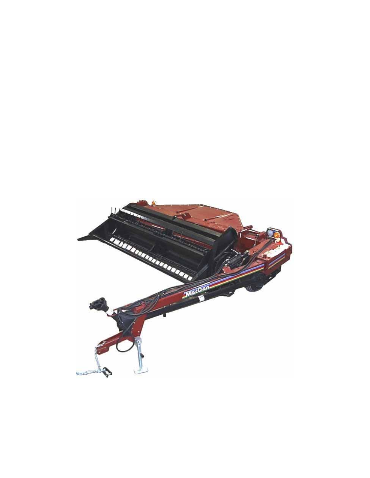
Your new MacDon Model 4000 Mower Conditioner is designed to cut, condition and lay in windrows, a wide
variety of grasses and hay crops.
Use this manual as your first source of information about the machine. If you follow the instructions given in
this manual, your Mower Conditioner will work well for many years.
The manual contains instructions for "Safety", "Operation", and "Maintenance/Service". In addition, "Unloading
and Assembly" information is given towards the back of this book.
CAREFULLY READ ALL THE MATERIAL PROVIDED BEFORE ATTEMPTING TO UNLOAD, ASSEMBLE,
OR USE THE MACHINE.
Use the Table of Contents and the Index to guide you to specific areas. Study the Table of Contents to
familiarize yourself with how the material is organised.
Keep this manual handy for frequent re ference and to pass on to new ope ra tors or ow ners. Call y o ur Deal er
if you need assistance, information, or additional copies of this manual.
NOTE: Right hand (R/H) and left hand (L/H) designations are determined from the operator’s position, facing
forward.
1
Page 2

TABLE OF CONTENTS
PAGE
INTRODUCTION .....................................................................................................................................1
SERIAL NUMBER LOCATION ................................................................................................................4
SAFETY
Safety Alert Symbol.......................................................................................................................5
Signal Words .................................................................................................................................5
Safety Signs...................................................................................................................................6
General Farm Safety .................................................................................................................. 7,8
SPECIFICATIONS
Mower Conditioner....................................................................................................................9,10
Tractor Requirements.................................................................................................................. 10
Torque Specifications............................................................................................................. 11,12
Bearing Installation......................................................................................................................12
OPERATION
Your Responsibilities as an Owner/Operator............................................................................... 13
To the New Operator...................................................................................................................13
Preparing the Tractor...................................................................................................................14
Preparing the Mower Conditioner................................................................................................15
Attaching Mower Conditioner to Tractor......................................................................................16
Detaching Mower Conditioner from Tractor.................................................................................17
Break-In Period............................................................................................................................18
Pre-Starting Checks: Annual .......................................................................................................19
Pre-Starting Checks: Daily........................................................................................................... 20
Operate Correctly ........................................................................................................................21
Lift Cylinder Stop - Raising and Lowering the Machine...............................................................22
Positioning the Hitch....................................................................................................................23
Engaging the PTO.......................................................................................................................24
Opening the Field ........................................................................................................................24
Cutting Width...............................................................................................................................24
Cornering..................................................................................................................................... 24
Operating Variables:
Ground Speed................................................................................................................... 25
Reel Speed........................................................................................................................26
Reel Position................................................................................................................27,28
Cutting Height - Skid Plates ..............................................................................................28
Cutterbar Angle.................................................................................................................29
Header Flotation................................................................................................................30
Roll Gap ............................................................................................................................ 31
Forming Shields ................................................................................................................ 32
Light Crop Deflectors .....................................................................................................32
Feed Pan Extensions.....................................................................................................33
Haying Tips:
Topsoil Moisture................................................................................................................33
Climate and Topography................................................................................................... 34
Swath / Windrow Characteristics ......................................................................................34
Running Tractor Tire on Previously Cut Swath................................................................. 34
Raking and Tedding..........................................................................................................34
Chemical Drying Agents....................................................................................................34
Unplugging the Mower Conditioner: Knife................................................................................... 35
Unplugging the Mower Conditioner: Rolls ...................................................................................35
Shut-Down Procedure .................................................................................................................36
Transporting the Mower Conditioner ...........................................................................................36
Storage Procedure....................................................................................................................... 37
2
Page 3

TABLE OF CONTENTS
MAINTENANCE/SERVICE
Service Procedures .....................................................................................................................38
Recommended Lubricants...........................................................................................................39
Capacities of Enclosed Drives.....................................................................................................39
Greasing the Mower Conditioner..........................................................................................40 - 43
Linkage Ball Joints.......................................................................................................................44
Hydraulics....................................................................................................................................45
Electrical......................................................................................................................................45
Main Drive:
Main Gearbox Lubricant.................................................................................................... 46
Main Gearbox Removal ....................................................................................................46
Over-Running Clutch.........................................................................................................47
Knife and Knife Drive:
Knife Lubrication................................................................................................................ 48
Knife Sections ...................................................................................................................48
Knife Removal and Installation..........................................................................................49
Knife Storage - ToolBox....................................................................................................49
Guards ..............................................................................................................................50
Knife Clips.........................................................................................................................50
Knife Drive Belt Tension....................................................................................................51
Knife Drive Belt Replacement ...........................................................................................51
Wobble Box Mounting Bolts..............................................................................................52
Wobble Box Lubricant....................................................................................................... 52
Reel and Reel Drive:
Reel Drive Belt Tension.....................................................................................................53
Reel Drive Belt Replacement............................................................................................53
Reel Drive Chain Lubricant ...............................................................................................54
Reel Drive Chain Tension ................................................................................................. 54
Reel Tines.........................................................................................................................54
Reel Shaft R/H Bearing Access ........................................................................................ 54
Roll Timing...................................................................................................................................55
Wheels and Tires:
Wheel Bolts.......................................................................................................................56
Tire Inflation ......................................................................................................................57
Maintenance Schedule...........................................................................................................58,59
Maintenance Record....................................................................................................................60
PAGE
TROUBLE SHOOTING...................................................................................................................61 - 64
ATTACHMENTS:
Four or Six Bat Reel ....................................................................................................................65
Stub Guard Conversion Kit..........................................................................................................65
UNLOADING AND ASSEMBLY......................................................................................................66 - 70
INDEX .....................................................................................................................................71,72
3
Page 4

SERIAL NUMBER LOCATION
Record the serial number in the space provided.
Mower Conditioner:
Serial number plate (A) is located on the bac k of
the drives frame.
NOTE: When ordering parts and service, be sure
to give your dealer the complete and proper serial
number.
A
SERIAL PLATE LOCATION
4
Page 5

SAFETY ALERT SYMBOL
This safety alert symbol indicates important safety messages in this manual and
on safety signs on the mower conditioner.
This symbol means:
ATTENTION !
BECOME ALERT !
YOUR SAFETY IS INVOLVED !
Carefully read and follow the safety message accompanying this symbol.
Why is SAFETY important to you?
3 BIG REASONS
• ACCIDENTS DISABLE AND KILL
• ACCIDENTS COST
• ACCIDENTS CAN BE AVOIDED
SIGNAL WORDS
SAFETY
Note the use of the signal words DANGER, WARNING, and CAUTION with safety messages. The appropriate
signal word for each message has been selected using the following guidelines:
DANGER – Indicates an imminently hazardous situation that, if not avoided, will result in death or
serious injury.
WARNING – Indicates a potentially hazardous situation that, if not avoided, could result in death
or serious injury. It is also used to alert against unsafe practices.
CAUTION – Indicates a potentially hazardous situation that, if not avoided, may result in minor or
moderate injury. It is also used as a reminder of good safety practices.
5
Page 6

SAFETY
SAFETY SIGNS
• The safety signs reproduced below appear on the windrower at the locations listed.
• Keep safety signs clean and legible at all times
• Replace safety signs that are missing or become illegible.
• If original parts on which a safety sign was installed are replace d, be su re the re pair part al so bears
the current safety sign.
• Safety signs are available from your Dealer Parts Department.
To install safety signs:
1. Be sure the installation area is clean and dry.
2. Decide on the exact location before you remove the decal backing paper.
3. Remove the smaller portion of the split backing paper.
4. Place the sign in position an d slo w ly peel back t he remainin g p aper, smo ot hing th e sign as it is
applied.
5. Small air pockets can be smoothed out or pricked with a pin.
6
Page 7

GENERAL SAFETY
PROTECT YOURSELF
BE PREPARED FOR EMERGENCIES
The following are general farm
safety precautions that should be
part of your operating pr oce dur e for
all types of machinery.
1. Protect yourself.
When assembling, operating and servicing
machinery wear all the protective clothing
and personal safety devices that COULD be
necessary for the job at hand. Don’t take
chances.
You may need:
· a hard hat.
· protective shoes with slip resistant soles.
· protective glasses or goggles.
· heavy gloves.
· wet weather gear.
· respirator or filter mask.
· hearing protec ti on. Be awar e tha t pr olon ged
exposure to loud noise can cause
impairment or loss of hearing. Wearing a
suitable hearing protective device such as
earmuffs (A) or earplugs (B) protects
against objectionable or loud noises.
SAFETY
2. Provide a first-aid kit for use in case of
emergencies.
3. Keep a fire extinguisher on the machine. Be
sure the extinguisher is properly
maintained and be familiar with its proper
use.
4. Keep young children away from machinery
at all times.
5. Be aware that accidents often happen when
the operator is tired or in a hurry to get
finished. Take the time to consider the
safest way. Never ignore warning signs of
fatigue.
PROTECT AGAINST NOISE
7
Page 8

GENERAL SAFETY (continued)
NEVER WEAR LOOSE
KEEP SERVICE AREA CLEAN AND DRY
6. Wear close-fitting clot hing and co ver long
hair. Never wear dangling items such as
scarves or bracelets.
7. Keep hands, feet, clothing and hair away
from moving parts. Never attempt t o clear
obstructions or objects from a machine
while the engine is running.
8. Keep all shields in place. Never alter or
remove safety equipment.
driveline guards can rotate independently
of the shaft and can telescope freely.
9. Use only service and repair parts made or
approved by the equipment manufacturer.
Substituted parts may not meet strength,
design, or safety requirements.
Make sure
SAFETY
OR DANGLING CLOTHES
10. Do not modify the machine. Unauth orized
modifications may impair the function
and/or safety and affect machine life.
11. Stop engine and remove key from ignition
before leaving operator’s seat for any
reason. A child or even a pet could engage
an idling machine.
12. Keep the area used for servicing machinery
clean and dry. Wet or oily floors are
slippery. Wet spo ts c a n b e da nge r ous whe n
working with electrical equipment. Be sure
all electrical outlets and too ls are properly
grounded.
13. Use adequate light for the job at hand.
14. Keep machinery clean. Straw and chaf f o n
a hot engine are a fire hazard. Do not allow
oil or grease to accumulate on service
platforms, ladders or controls. Clean
machines before storage.
15. Never use gasoline, naphtha or any volatile
material for cleaning purposes. These
materials may be toxic and/or flammable.
KEEP AWAY FROM MOVING PARTS
16. When storing machinery, cover sharp or
extending components to prevent injury
from accidental contact.
8
Page 9

SPECIFICATIONS
DIMENSIONS 9 FT. MOWER CONDITIONER
Overall Width:
Transport Position 147.5 in. (3750 mm)
Field Position 167.0 in. (4243 mm)
Overall Length:
Transport Position 159.8 in. (4059 mm)
Field Position 166.8 in. (4238 mm)
Overall Height:
Transport Position 59.5 in. (1510 mm)
Field Position 42.6 in. (1083 mm)
Weight 3318 lbs. (1505 kg)
CUTTERBAR
Cutterbar Width 111 in. (2819 mm)
Cutting Height (on skids) 1 to 4 in. (25 to 100 mm)
at 9° guard angle
Guard Angle (adjustable) 6° to 12° below horizontal
HEADER
Header Flotation -2.5 to +6.7 in. (-64 to +170 mm)
Maximum Header Lift 21.5 in. (545 mm) to guard tip
KNIFE
Drive Type Belt driven wobble box (enclosed oil bath)
Speed 1620 strokes or 810 cycles per minute
Stroke 3 in. (76 mm)
Sections Over-serrated, low shoulder
REEL
Drive Type Belt primary to chain final
Reel Type 5 bats (4 or 6 bats optional), replaceable steel pick-up tines,
cam action, polymer tine tube bearings
Diameter 42.5 in. (1080 mm)
Tine Tip (Peripheral) Speed 6.6, 7.0, 7.5 or 7.9 mph (10.6, 11.3, 12.0 or 12.7 km/h)
Rotational Speed 53, 56, 60 or 63 rpm
Length 104.3 in. (2650 mm)
9
Page 10

SPECIFICATIONS
CONDITIONER ROLLS 9 FT. MOWER CONDITIONER
Drive Type Gear driven through telescoping u-joints
Roll Type Helical intermeshing fabric reinforced rubber
Or
Helical intermeshing steel
Roll Diameter Rubber: 9.5 in (242 mm) Steel: 10.0 in (254 mm)
Roll Length 105.8 in (2687 mm)
Roll Speed 729 rpm
WHEELS
Tread Width 100 in (2540 mm)
Tires 9.5L – 14 I1 Rib Implement
Tire Pressure 20 psi (138 kPa)
MATERIAL DISCHARGE
Minimum Width 33.3 in (845 mm)
Maximum Width 84.9 in (2156 mm) (wider in heavy crop)
Number of Width Settings 7
OPERATING SPEED
Range up to 8 mph (13 Km/h)
Recommended Speed for Most Conditions 5 mph (8 Km/h)
TRACTOR REQUIREMENTS
Minimum Power 35 hp (26 kW)
Minimum Weight 5000 lbs. (2268 kg)
PTO 540 rpm with ASAE Standard location
Drawbar Clevis or straight, ASAE Standard hitch location
Hydraulics:
Type Two double acting remote circuits
Minimum Pressure 1350 psi (9300 kPa)
(SPECIFICATIONS AND DESIGN ARE SUBJECT TO CHANGE WITHOUT
NOTICE OR OBLIGATION TO REVISE UNITS PREVIOUSLY SOLD.)
10
Page 11
TORQUE SPECIFICATIONS
8.8
10.9
N·m
[lb-ft]
N·m
[lb-ft]
M3
0.5
[.4]
1.8
[1.3]M43
[2.2]
4.5
[3.3]M56
[4]9[7]M610
[7]15[11]M825
[18]35[26]
M1050[37]70[52]
M1290[66]
125
[92]
M14
140
[103]
200
[148]
M16
225
[166]
310
[229]
M20
435
[321]
610
[450]
M24
750
[553]
1050
[774]
M30
1495
[1103]
2100
[1550]
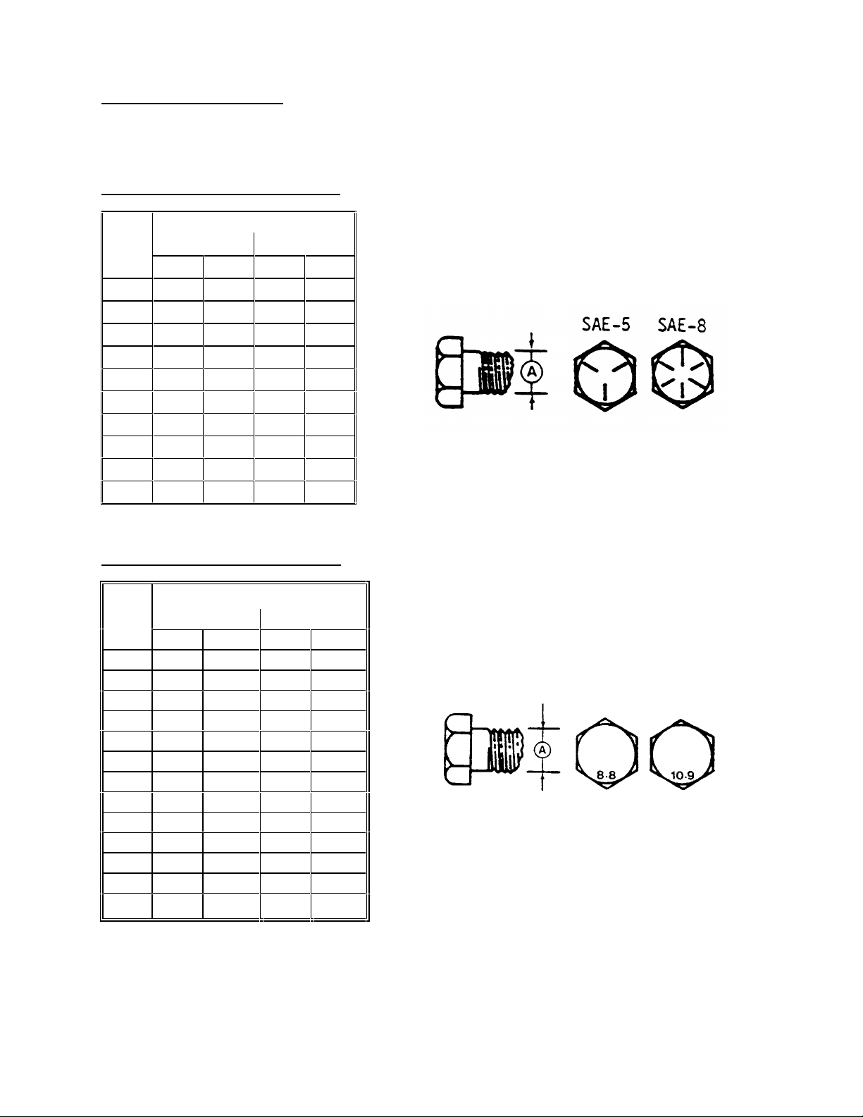
CHECKING BOLT TORQUE
The tables shown below give correct torque values for various bolts and capscrews. Tighten all bolts to the
torques specified in chart unless otherwise not ed thr ough out th is manual. Check tightn ess of bolts periodi cal ly,
using bolt torque chart as a guide. Replace hardware with the same strength bolt.
ENGLISH TORQUE SPECIFICATION
NC Bolt Torque*
Bolt
Dia.
"A" N·m [lb-ft] N·m [lb-ft]
1/4" 12 [9] 15 [11]
5/16" 24 [18] 34 [25]
3/8" 43 [32] 56 [41]
7/16" 68 [50] 95 [70]
1/2" 102 [75] 142 [105]
9/16" 149 [110] 202 [149]
5/8" 203 [150] 271 [200]
3/4"
7/8" 569 [420] 813 [600]
1" 867 [640] 1205 [890]
SAE 5 SAE 8
359 [265]
495 [365]
METRIC TORQUE SPECIFICATIONS
Bolt
Dia.
"A"
M36 2600 [1917] 3675 [2710]
Torque figures indicated above are valid for non-greased or non-oiled threads and heads unless otherwise
specified. Do not grease or oil bolts or capscrews unles s specified in this manual. W hen using locking
elements, increase torque values by 5%.
Bolt Torque*
* Torque value for bolts and capscrews are identified by their head markings.
11
Page 12
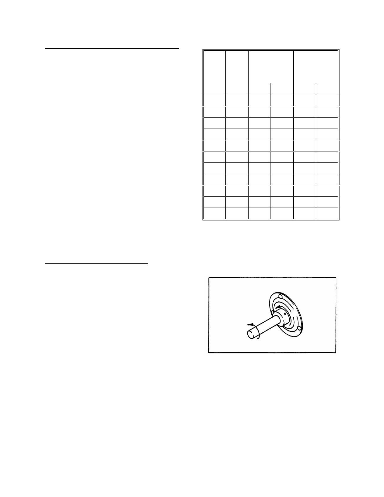
TORQUE SPECIFICATIONS
N·m
[lb-ft]
Flats
Turns
TIGHTEN COLLAR IN DIRECTION
SHAFT ROTATES
TIGHTENING HYDRAULIC O-RING FITTINGS*
1. Inspect O-ring and seat for dirt or obvious
defects.
2. O n angle fittings, back the lock nut off until
washer bottoms out at top of groove.
3. Hand tighten f itting until back up washer or
washer face (if straight fitting) bottoms on face
and O-ring is seated.
4. Position angle fittings by unscrewing no more
than one turn.
5. Tighten straight fittings to torque shown.
6. T ighten angle fittings to torque shown while
holding body of fitting with a wrench.
* The torque values shown are based on
lubricated connections as in reassembly
.
Recommended
Turns to Tighten
(after finger
tightening)
Thread
Size
(in.)
Nut Size
Across
Flats
(in.)
Torque Value*
3/8 1/2 8 [6] 2 1/3
7/16 9/16 12 [9] 2 1/3
1/2 5/8 16 [12] 2 1/3
9/16 11/16 24 [18] 2 1/3
3/4 7/8 46 [34] 2 1/3
7/8 1 62 [46] 1-1/2 1/4
1-1/16 1-1/4 102 [75] 1 1/6
1-3/16 1-3/8 122 [90] 1 1/6
1-5/16 1-1/2 142 [105] 3/4 1/8
1-5/8 1-7/8 190 [140] 3/4 1/8
1-7/8 2-1/8 217 [160] 1/2 1/12
SEALED BEARING INSTALLATION
1. Clean shaft and coat with rust preventative.
2. Install flangette, bearing, flangette and lock
collar. The locking cam is only on on e side of
the bearing.
3. Install (but do not tighten) the flangette bolts.
4. W hen the shaft is located correctly, lock the
lock collar with a punch. The collar should be
locked in the same direction the shaft rotates.
Tighten the setscrew in the collar.
5. Tighten the flangette bolts.
6. Loosen the flangette bolts on the mating
bearing one turn and re-tighten. This will a llow
the bearing to line up.
12
Page 13
OPERATION
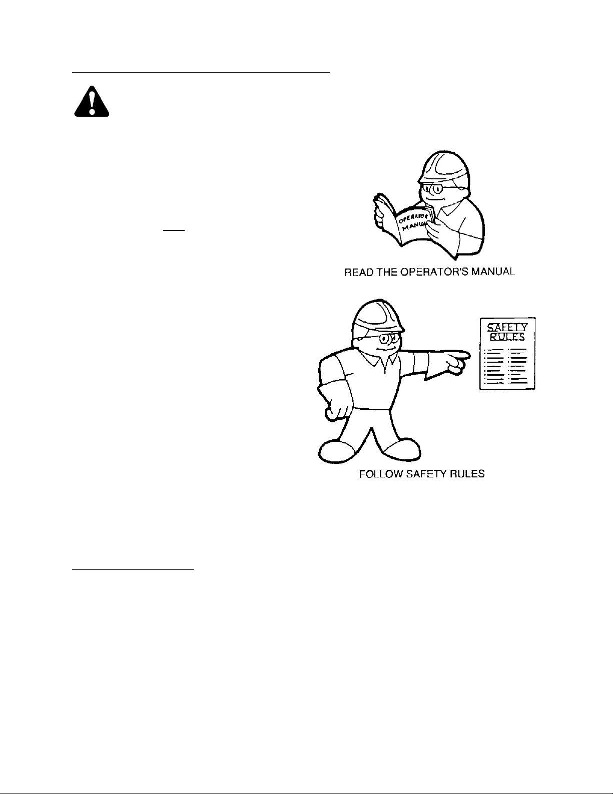
YOUR RESPONSIBILITIES AS AN OWNER/OPERATOR
CAUTION:
1. It is your responsibility to read and
understand this manual completely before
operating the windrower. Contact your
dealer if an instruction is not clear to you.
2. Follow all safety messages in th e manual
and on safety signs on the machine.
3. Remember that YOU
Good safety practices protect you and the
people around you.
4. Before allowing anyone to operate the
windrower, for however short a time or
distance, make sure they have been
instructed in its safe and proper use.
5. Review the manual and all safety related
items with all operators annually.
6. Be alert for other operators not using
recommended procedures or not following
safety precautions. Correct these mistakes
immediately, before an accident occurs.
7. Do not modify the machine. Un authorized
modifications may impair the function
and/or safety and affect machine life.
8. The safety information given in this manual
does not replace safety codes, insurance
needs, or laws governing your area. Be sure
your machine meets the standards set by
these regulations.
are the key to safety.
TO THE NEW OPERATOR
It’s natural for an operator to be anxious to get
started with a new machine. Please take the time
to familiarize yourself with the windrower by
reading the Operator’s Manual and safety signs
before attempting operation.
13
Page 14
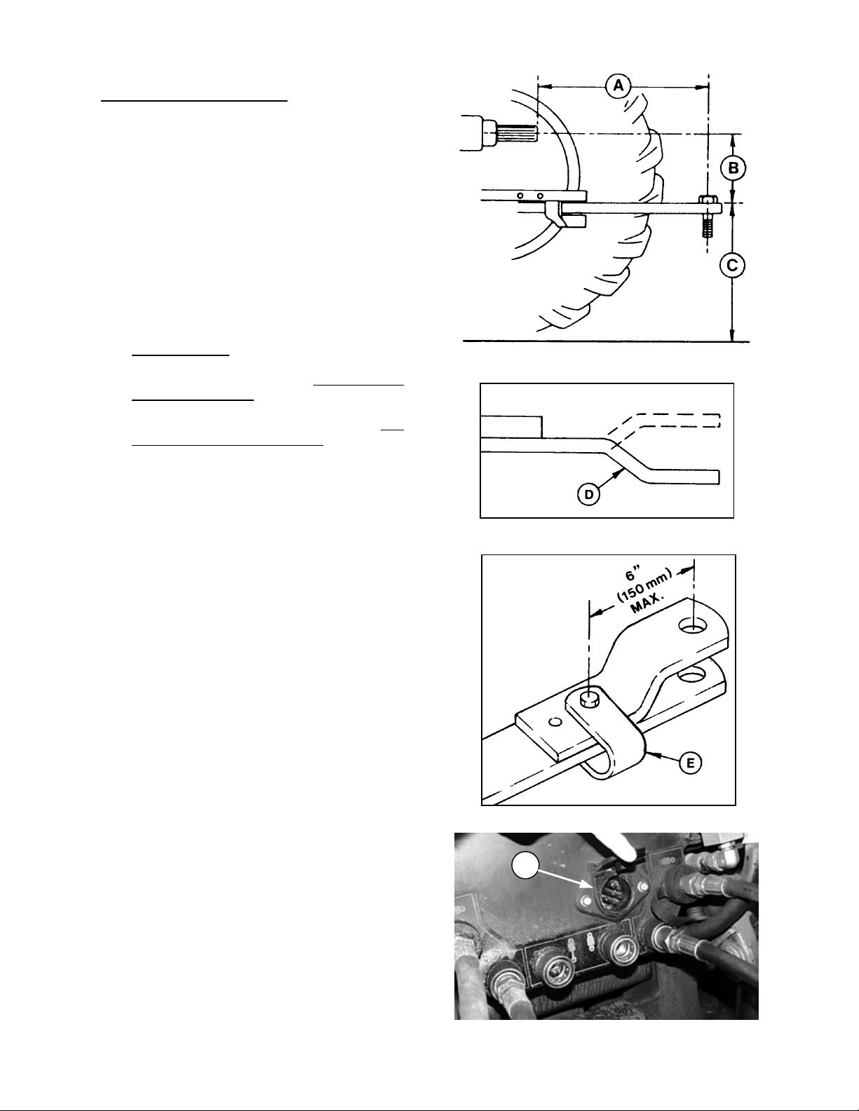
OPERATION
PREPARING THE TRACTOR
1. Select proper tractor size. The minimum
power required is 35 hp (26 kw). Also,
minimum tractor weight is 5000 lbs. (2268 kg)
and minimum hydraulic press ure r equired is
1350 psi (9300 kPa).
2. Adjust tractor drawbar to meet ASAE
Standard specifications as lis ted below. An
improperly located drawbar may damage the
universal joints of the implement driveline,
and/or affect header flotation and guard
angle.
Be sure the following specifications are met:
(A) 14 in. (356 mm) for 540 rpm
(B) 6 to 12 in. (152 to 305 mm) with 8 in. (203
mm) recommended.
(C) 13 to 17 in. (330 to 432 mm) from ground with
16 in. (406 mm) recommended.
NOTE: An offset drawbar (D) can be turned over
if required to meet specifications (B) and (C).
3. Secur e the drawbar so the hitch pinhole is
directly below the driveline.
NOTE: If the tractor has a 3-point hitch, r aise the
lower links as high as possible, to prevent
damage.
4. Use 540 rpm PTO speed only.
5. Attach support (E) for hitch chain to s uitable
location on tractor drawbar, maxim um 6 in.
(150 mm) from hitch pinhole.
STANDARD DRAWBAR SPECIFICATIONS
OFFSET TRACTOR DRAWBAR
6. Tractor must be equipped with a seven
terminal electrical outlet (F ) to supply power
to the mower conditioner warning lights.
ATTACH SUPPORT FOR HITCH CHAIN
F
SEVEN TERMINAL ELECTRICAL OUTLET
14
Page 15
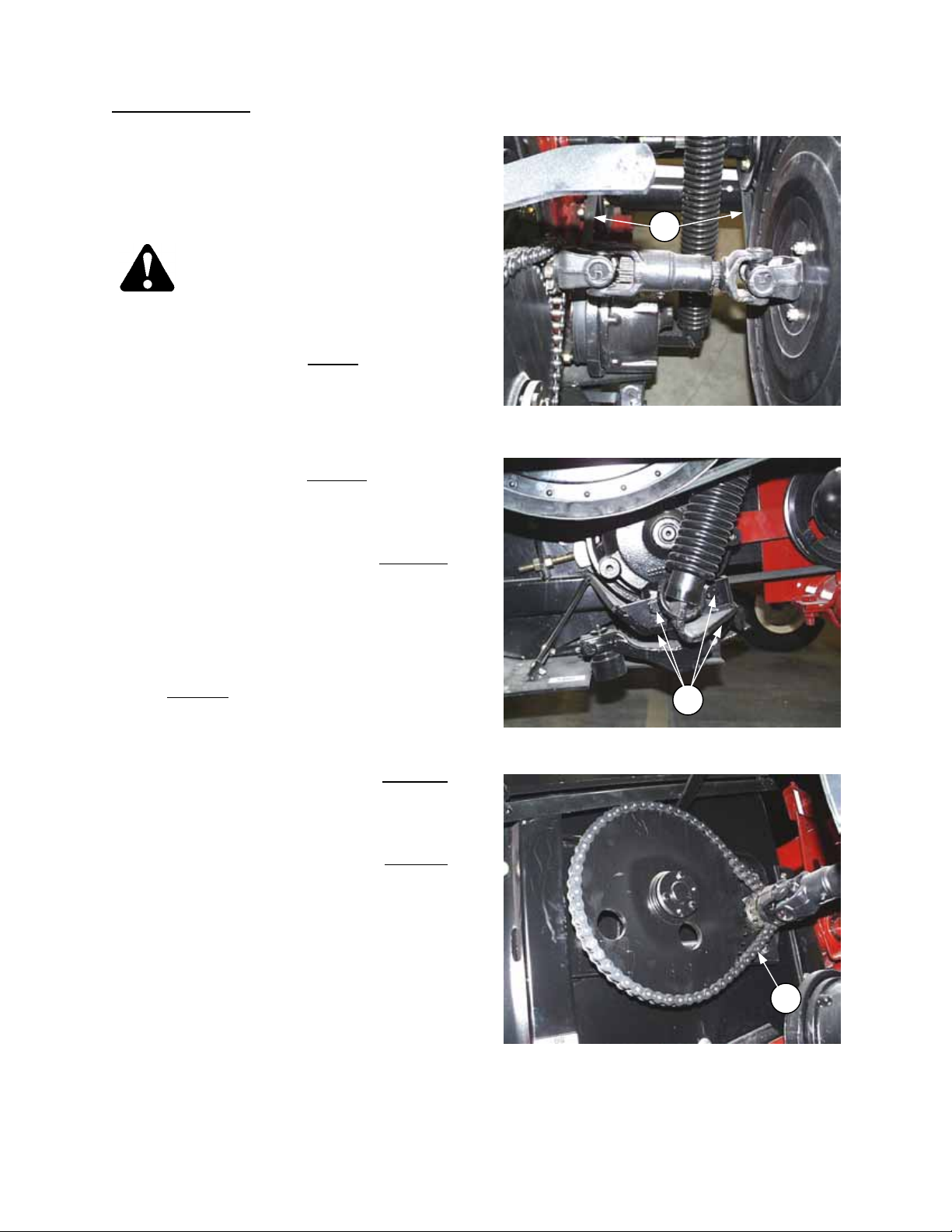
PREPARING THE MOWER CONDITIONER
1. Use correct hitch type:
For tractors with clevis type drawbar, use hitch as
shown at (A).
For tractors with straight drawbar, re-position bar
(B) to give clevis type hitch.
OPERATION
A
HITCH CONFIGURATION FOR TRACTORS
WITH CLEVIS TYPE DRAWBAR
B
HITCH CONFIGURATION FOR TRACTORS
2. With the tractor drawbar adjusted to the
WITH STRAIGHT DRAWBAR
recommendations listed under “Preparing the
Tractor”, use the hanger beari n g ad justment (C)
so that the implement drive line (D) is as near
level as possible going to the tractor.
IMPORTANT: The telescoping implement driveline
(D) should slide under hand pressure. Grease if
required.
3. Check the tires and inflate if necessary.
D
Recommended pressure is 20 psi (138 kPa).
CAUTION: When inflating tires, use a
clip-on chuck and extension hose long
enough to allow you stand to one side
ADJUST DRIVELINE HANGER BEARING
and not facing the tire.
4. Check for proper assembly and adjustment and make sure that all bolts are tightened securely.
C
5. Check the tension of both belts and adjust if required. Check the over-running clutch for proper
spring lengths. See Maintenance/Service section.
6. Lubricate the machine completely and check the oil levels of the main gearbox (two places) and the
wobble box. Check that breathers have been installed in boxes. See Maintenance/Service section.
7. Install quick coupler tips, matching the tractor to be used, on the hose ends.
15
Page 16
OPERATION
ATTACHING MOWER CONDITIONER TO TRACTOR
CAUTION: Shut off tractor, engage
parking brake and remove key
before working around hitch.
CAUTION: N eve r a tta ch mo wer hi tc h
to tractor rear axle or three-point
hitch arms.
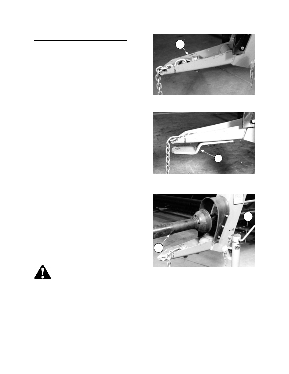
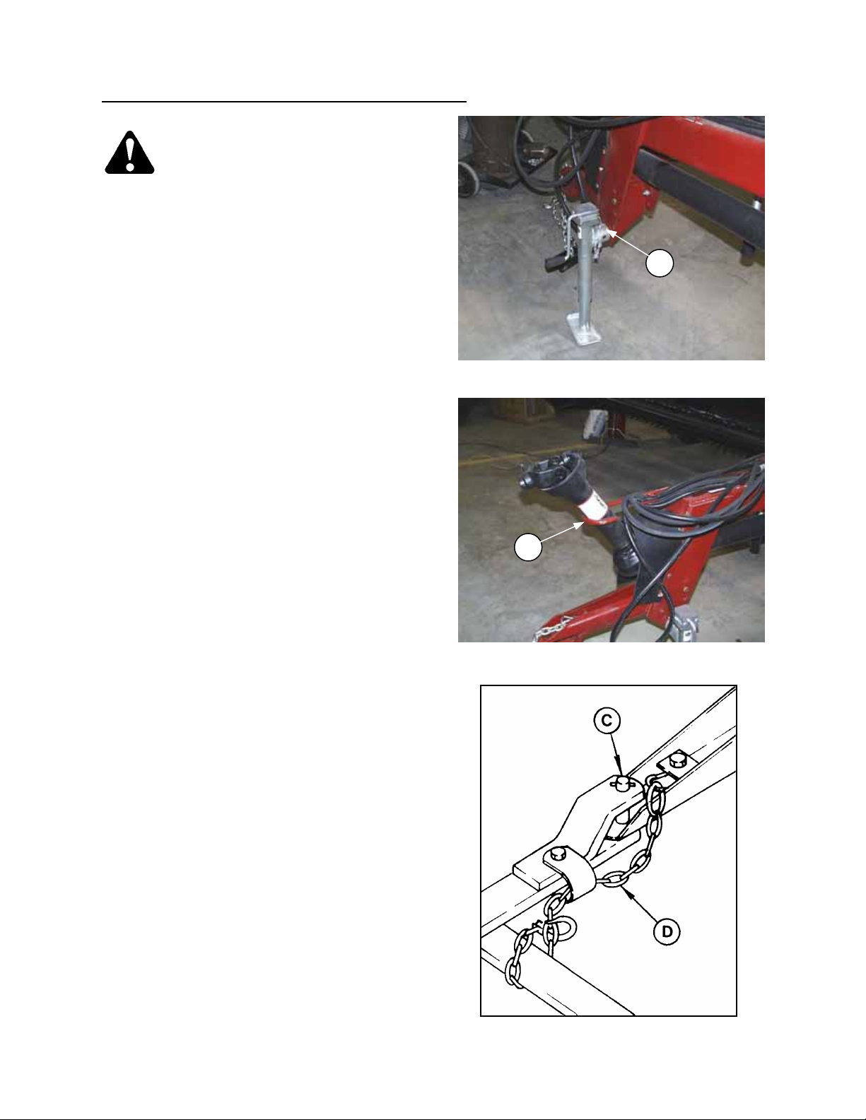
1. Attach mower conditioner to tractor drawbar
with a 3/4 to 1 inch diameter hitch pin and
secure with a spring locking pin or other
suitable fastener.
CAUTION: To prevent damage to
driveline guards, use a drawbar
hitch pin with a low head.
2. Route hitch chain from mower conditioner
through chain support (A), around drawbar
support and lock hook (B) on chain.
INSTALL HITCH PIN AND CHAIN
IMPORTANT: Adjust chain length to remove all
slack except what is needed for turns.
3. Remove weight from jack. Pull pin securing jack
and move to storage position (C) on drives
frame.
4. Push button (D) on telescoping driveline yoke
and slide yoke onto tractor PTO shaft. Be sure
yoke locks in position on shaft.
5. Connect hydraulic hoses to the remote cylinder
control valves on tractor.
6. Connect mower conditioner wiring harness plug
to outlet on tractor.
C
JACK STORAGE
D
16
ATTACH DRIVELINE TO PTO
Page 17
OPERATION
STORE DRIVELINE
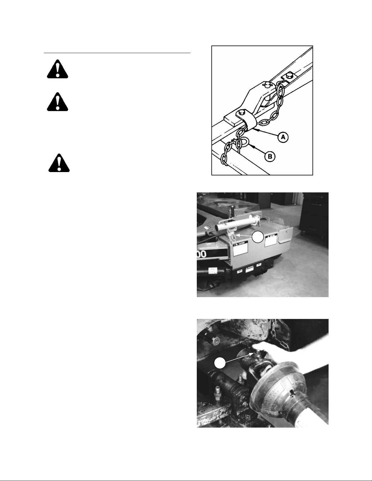
DETACHING MOWER CONDITIONER FROM TRACTOR
CAUTION: To prevent accidental
movement of tractor, shut off
engine, engage parking brake, and
remove key.
To maintain stability, always lower
the machine completely. Block
mower conditioner wheels before
detaching from tractor.
Park machine on flat level surface.
Move remote cylinder control valve
lever back and forth to rel ie ve stor ed
hydraulic pressure.
A
1. Pull pin securing jack and move to working
position (A).
2. Lower jack to take weight off tractor drawbar.
3. Push button on telescoping driveline yoke to
unlock grip on PTO shaft. Remove driveline
from PTO and store in support (B).
4. Disconnect hydraulic hoses and electrical
harness. Store so ends are off ground.
5. Remove hitch pin (C) and unhook chain (D)
from tractor. Wrap chain around mower
conditioner hitch for storage.
MOVE JACK TO WORKING POSITION
B
6. Slowly drive tractor away from mower
conditioner.
REMOVE HITCH PIN AND CHAIN
17
Page 18
OPERATION
CHECK WOBBLE BOX MOUNTING BOLTS
BREAK-IN PERIOD
1. After attaching mower conditioner to tractor for
the first time, operate the machine slowly for 5
minutes, watching and listening FROM THE
TRACTOR SEAT for binding or interfering
parts.
CAUTION: Before investigating an
unusual sound or attempting to
correct a problem, shut off tract or,
engage parking brake and remove
key.
2. Check both belts (A) after 5 hours operation for
initial stretch. Tighten as necessary. (See
Maintenance/Service section). Continue to
check the belts periodically for the first 50
hours.
3. Check hardware after 5 hours operation.
Tighten as necessary. See Specifications
section for recommended torques.
A
CHECK BELT TENSION
4. Check wheel bolt torque after 10 hours
operation and periodically thereafter (at least
every 100 hours).
Torque: 50 to 60 ft. lbs. (68 to 81 N⋅m)
5. Tighten the four wobble box mounting bolts (B)
after 10 hours operation and every 100 hours
thereafter. Torque to 200 ft. lbs. (270 N⋅m),
starting with the side mounting bolts.
6. Check reel drive chain (C) after 10 hours
operation for proper tension. See
Maintenance/Service section.
7. Change wobble box lubricant after 50 hours
operation and every 1000 hours (or 3 years)
thereafter. See Maintenance/Service section.
8. Until you become familiar with the s ound and
feel of your new mower conditioner, be extra
alert and attentive.
B
C
CHECK REEL DRIVE CHAIN TENSION
18
Page 19

OPERATION
PRE-STARTING CHECKS
Do the following at the start of each operating
season:
CAUTION:
1. Review the Operator’s Manual to refresh
your memory on safety and operating
recommendations.
2. Review all safety signs and other deca ls on
the mower conditioner and note hazard
areas.
3. Be sure all shields and guards are properly
installed and secured. Never alter or remove
safety equipment.
4. Be sur e you under st a n d an d ha v e p r a ct i c e d
safe use of all controls. Know t he capacity
and operating characteristics of the
machine.
5. Check the first aid kit and fire extinguisher.
Know where they are and how to use them.
Also:
6. Adjust tension on drive belts. See
Maintenance/Service section.
7. Perform all Annual maintenance. See
Maintenance/Service section.
19
Page 20

OPERATION
PRE-STARTING CHECKS
Do the following each day before start-up:
CAUTION:
1. Clear the area of other perso ns, pets etc.
Keep children away from machinery. Walk
around the windrower to be sure no one is
under, on or close to it.
2. Remove foreign objects f rom the machine
and surrounding area.
3. Wear close fitting clothing and protective
shoes with slip resistant soles.
As well, carry with you any protective
clothing and personal safety dev ices that
COULD be necessary through the day.
Don’t take chances.
You may need:
- a hard hat
- protective glasses or goggles
- heavy gloves
- respirator or filter mask
- wet weather gear.
PROTECT YOURSELF
4. Protect against noise. Wear a suitable
hearing protective device such as earmuffs
or earplugs to pr otect aga in st obj e ctio nable
or uncomfortable loud noises.
5. Check the machine for leaks or any parts
that are missing, broken, or not working
correctly.
NOTE: Use proper procedure when
searching for pressurized fluid leaks. See
"Hydraulics" in Maintenance/Service
section.
6. Be sure tractor and windrower are properly
attached, all controls are in neutral and
tractor brake is engaged.
7. Clean all lights and reflective surfaces on
the machine. Check lights for proper
operation.
8. Perform all Daily maintenance. See
Maintenance/Service section.
PROTECT AGAINST NOISE
20
Page 21

OPERATION
OPERATE CORRECTLY
CAUTION:
1. Follow all safety and operational instructions given in your tractor Operator’s Manual. If you do
not have a tractor manual, get one from your dealer and read it thoroughly.
2. Never attempt to start the tractor engine or operate the mower conditioner except from the tractor
seat.
3. Check the operation of all controls in a safe clear area before starting work.
4. Do not allow riders on tractor or mower conditioner.
5. Never start or move the machine until you are sure all bystanders have cleared the area.
6. Avoid travelling over loose fill, rocks, ditches or holes.
7. Drive slowly through gates and doorways.
8. If mowing ditch banks, us e extr eme caut ion. If the mo wer condi tione r hits an obst ructi on, the front
of the tractor will usually swerve towards the ditch.
9. When working on inclines, travel uphill or downhill when possible. Be sure to keep tractor
transmission in gear when travelling downhill.
10. Never attempt to get on or off a moving tractor.
11. Do not get off the tractor while the mower conditioner is in operation.
12. Stop tractor engine and remove key before adjusting or removing plugged material from the
machine. A child or even a pet could engage the drive.
13. Check for excessive vibration and unusual noises. If there is any indication of trouble, shut down
and inspect the machine. Follow proper shutdown procedure:
- engage tractor brake
- disengage PTO
- turn off engine and remove key
- wait for all movement to stop
- dismount and engage cylinder stop before inspecting rais ed machine.
14. Operate only in daylight or good artificial light.
IMPORTANT: Correct operation reduces crop loss and allows cutting of more acres. The length of service
you receive from your mower conditioner depends upon timely maintenance and proper adjustments.
Satisfactory function of this machine in all crop conditions requires making proper adjustments to suit various
conditions.
21
Page 22
OPERATION
LIFT CYLINDER STOP
LIFT CYLINDER STOP
(RAISING AND LOWERING MOWER CONDITIONER)
WARNING: To avoid bodily injury or
death from fall of raised machine,
always engage lift cylinder stop
before going under mower
conditioner for any reason.
To engage cylinder stops:
1. Raise machine to maximum height by
activating remote cylinder control valve in
tractor.
2. Remove pin (A) and move support (B)
forward, aligning hole in support with slot in
frame lug.
3. Replace pin (A) to secure the s upport in the
engaged position.
4. Lower machine slightly so support takes some
weight.
To lower mower conditioner:
1. Raise machine to maximum height to take
weight off support (B).
2. Remove pin (A) and move support back to
disengaged position.
3. Replace pin (A) to secure the support in
disengaged position.
4. Lower machine by activating remote cylinder
control valve in tractor.
22
Page 23

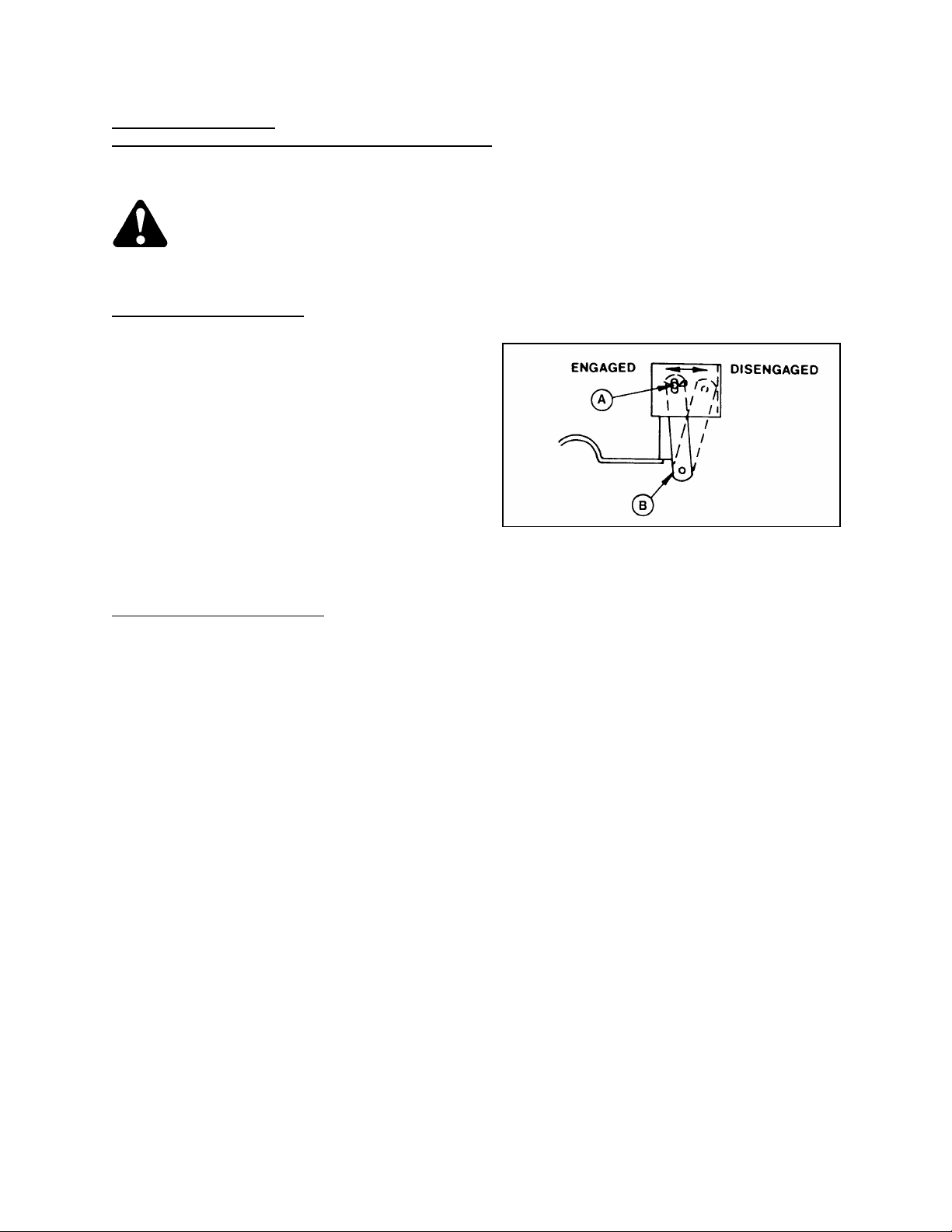
OPERATION
HITCH CYLINDER HYDRAULIC VALVE
POSITIONING THE HITCH
The mower conditioner hitch can be moved
between transport position (A) and f ield position
(B) with the hitch shift cylinder without moving the
tractor.
In the field, use a position that allows cutting a full
machine width while maintaining clearance
between the right tractor tire and the standing
material.
IMPORTANT: To avoid machine damage with
machine in field position and tractor turned sharply
right, do not activate hitch shift cylinder. Trac tor
tire can contact lean bar.
WARNING: Before transporting
mower conditioner, close hydraulic
valve (C) to prevent inadvertent
cylinder ext ens io n tha t would cau se
machine to swing out unexpectedly.
Closed position is with handle at 90º
to oil flow direction as shown. Open
position is with handle in line with
oil flow direction.
C
23
Page 24

OPERATION
ENGAGING THE P TO
DANGER: Be sure all bystanders are
clear of the machine before
engaging the PTO. Never leave
tractor seat with the PTO engaged.
Entanglement with rotating driveline
will cause serious injury or death.
The PTO should be engaged slowly, just before
the mower conditioner is moved up to the standing
crop.
Be sure tractor PTO is running at 540 rpm before
starting to cut.
Disengage the PTO when not operating the mower
conditioner.
OPENING THE FIELD
CAUTION: Check the work area
before starting operation. Look for
ditches, potholes, drop-offs, steep
slopes, stumps, standing water etc.
Remove any debris or f oreign objec t
that may be picked up and thro wn
out by the mower conditioner.
CLEAR THE AREA BEFORE ENGAGING PTO
If the operato r i s in famil i ar te rri t ory, the first swath
may be cut counter-clockwise (A) around the
outside. This allows a full cut for the back swath.
However, if there may be hidden obstacles or
holes along the field border it is better to cut the
first few swaths clockwise ( B), then cut the back
swath counter-clockwise after any obstacles have
been exposed.
CUTTING WIDTH
The left side of the machine should be run close to
the edge of the standing crop, taking a full cut.
CORNERING
Reduce speed, turn tractor sharply right as the
cutterbar comes to the edge of the standing crop.
Use the right wheel brake on the tractor to push
the machine back, then straighten out the tractor
along the new edge of crop. Do not raise mower to
make square corners.
OPENING THE FIELD - A
24
OPENING THE FIELD - B
Page 25

OPERATION
OPERATING VARIABLES
The eight variables covered here will affect the operation of your mower conditioner. You will quickly become
adept at adjusting the machine to give you the desired results.
1. GROUND SPEED
CAUTION: Reduce speed when turning, crossing slopes, or when travelling over rough
ground.
Tractor ground speed should not exceed 8 mph (13 km/h). For most crop conditions a ground speed of 5 mph
(8 km/h) has been found satisfactory.
Choose a ground speed that allows the knife to cut the crop smoothly and evenly.
The chart below indicates the relationship between ground speed and area cut for the 9 ft. mower conditioner.
Example: At ground speed of 5 mph (8 km/h) with a 9 ft. mower conditioner, the area cut would be
approximately 5 1/2 acres (2.3 hectares) per hour.
25
Page 26

OPERATING VARIABLES (continued)
OPERATION
2. REEL SPEED
For best feeding of the crop into the
conditioning rolls, reel speed should be jus t
faster than ground speed. This gently sweeps
material across knife into the rolls.
The reel speed is factor y set at 63 rpm . See
chart below for reel speed options.
position of:
rpm tine tip speed
mph (km/h)
53 6.6 (10.6) inside inside
56 7.0 (11.3) inside outside
60 7.5 (12.0) outside inside
63 7.9 (12.7) outside outside
In down and tangled crops, a faster reel speed
will result in a more even stubble height.
yoke
plate (B)
shim (F)
A
REEL DRIVE PULLEY ASSEMBLY
To change reel speed:
a. Loosen reel drive belt enough that it can be
removed from drive pulley (A) at main
gearbox. See "Reel Drive Belt" in
"Maintenance/Service" section for tension
adjustment procedure. Do not pry belt over
pulley.
b. Scratch an alignment m ark on pulley half ( A)
and yoke plate (B) to maintain roll timing on
re-assembly. Do not use pulley half (E) for
alignment.
c. Remove three bolts (C).
d. Collapse the driveline at the telescoping shaft
(D) and remove pulley half (E).
NOTE: Shim (F) is open one side and can be
removed once bolts are removed.
e. Re-assemble for desired reel speed,
positioning yoke plate (B) and shim (F) inside
or outside pulley halves as indicated in chart
above. Remember to align marks before
tightening bolts.
f. Replace belt and adjust belt tension.
53 RPM REEL SPEED
26
63 RPM REEL SPEED
Page 27

OPERATION
Wet or dead material collects on cutterbar,
OPERATING VARIABLES (continued)
3. REEL POSITION
Reel position has been found to be a cri tical factor in achieving good results in adverse conditions. The reel
position is factory set for average straight standing crop. It can be adjusted both ver tically and horizontally
(fore-aft) for different crop conditions.
See the chart below for recommended reel position in unusual crop conditions.
REEL POSITION CHART
Unusual Crop Condition Reel Position
Crop down or lodged.
plugging knife.
Short crop.
Thick stemmed or heavy standing crop.
To adjust reel horizontal (fore-aft) position:
a. Loosen nuts (A), four on L/H side, thr ee on
R/H side.
b. Move reel to desired position.
NOTE: T he reel slides in angled slots which
lower the reel as it i s moved forw ard, a nd rai se
the reel as it is moved back.
c. Tighten nuts (A).
Forward and down (also increase reel speed).
Back and down (close to guards).
Back.
Up and forward.
REEL POSITION ADJUSTMENTS - LEFT SIDE
To adjust reel vertical position:
a. Loosen nuts (A), four on L/H side, thr ee on
R/H side.
b. Adjust reel up or down using lock nuts ( B) on
eyebolts, both sides.
c. Tighten nuts (A), total 7.
NOTE: Chain tension is not affected by reel
position adjustments.
REEL POSITION ADJUSTMENTS - RIGHT SIDE
27
Page 28

OPERATION
CUTTING HEIGHT ADJUSTMENT
OPERATING VARIABLES (continued)
3. REEL POSITION (continued)
After adjusting reel position:
a. Check that the reel rotates freely. Tines must not contact feed pan, header beam, guards or ground.
b. Check that the reel is adjus ted to the same position on both sides. Reel tube should appear par allel to
header beam from both side and front.
c. Check header float and adjust if required. See "Header Flotation" in this section.
4. CUTTING HEIGHT
Control cutting height with skid plates, not with the
hydraulic cylinder. Having the header "ride" on the
skid plates allows the three-point float linkage to
float header over obstacles and follow ground
contours, rather than supporting the header with
the cylinder.
NOTE: Lowering the skid plates raises the cutting
height. This may be desirable in stony conditions,
to reduce damage to cutting components. Also, a
longer stubble length helps material dry faster.
To adjust cutting height:
WARNING: To avoid bodily injury or
death from unexpected start-up or
fall of raised machine, stop engine,
remove key and engage lift cylinder
stop before going under machine to
adjust skid plates or for any reason.
a. Remove pin (A) at each skid plate.
b. Raise or lower skid plate (B) to desired
position.
c. Replace pin (A).
After adjusting cutting height:
a. Check that skid plates are adjusted to the
same position.
b. Check header float and adjust if required. See
"Header Flotation" in this section.
A
B
WARNING: Stones or other foreign objects carried into the conditioner rolls can be ejected
with force in ANY direction. Keep everyone several hundred feet away from your operation
and be sure you are adequately protected. See "General Safety" in Safety section for
recommended protective wear.
28
Page 29

OPERATION
OPERATING VARIABLES (continued)
5. CUTTERBAR ANGLE
Cutterbar angle can be varied from 6° to 12° below horizontal. Choose an angle that maximizes performance
for your crop and field conditions. A flatter guard angle provides better clearance in stony condi tions while a
steeper guard angle is required in down crops for better lifting action.
To adjust cutterbar angle:
a. Loosen nut (A).
b. To decrease (flatten) cutterbar angle, turn nut (B) clockwise.
c. To increase (steepen) cutterbar angle, tun nut (B) counter-clockwise.
d. Tighten nut (A) to 160 ft.lbs. (210 N.m)
After adjusting cutterbar angle:
a. Check cutting height and adjust if required. See "Cutting Height" in this section.
b. Check header float and adjust if required. See "Header Flotation" in this section.
A
B
CUTTERBAR ANGLE ADJUSTMENT
29
Page 30

OPERATION
HEADER FLOTATION ADJUSTMENT
OPERATING VARIABLES (continued)
6. HEADER FLOTATION
Header flotation springs are normally set so 70 l bs.
force (311 N) is required to lif t each end of the
header just off the ground.
In rough or stony conditions, it may be desirable to
change setting to 35-50 lbs. (156-222 N) to protect
cutting components.
NOTE: When float setting is light, it may be
necessary to use a slower ground speed to avoid
excessive bouncing and leaving a ragged cut.
To increase header flotation, which decreases the
force required to lift header:
a. Back jam nut (A) away from spring.
b. Turn adjuster bolt (B) further into spring to
increase flotation.
c. Tighten jam nut (A) against spring insert (C) to
secure the setting.
IMPORTANT: Float setting (or lifting f orce) mus t
be equal on both springs. Weight difference
between left and right ends requires different
spring lengths to achieve equal floa t at both end s.
Note that other operating variable adjustments
may affect float setting. Check the float and
readjust if necessary after adjusting reel position,
cutting height, or cutterbar angle. Also, if using a
tractor with drawbar height different than 16 i nches
(406 mm), flotation will be affected. Adjust as
required.
B
A
C
30
Page 31

OPERATION
OPERATING VARIABLES (continued)
7. ROLL GAP
WARNING: To avoid bodily injury or
death from unexpected start-up or
fall of raised machine; stop engin e,
remove key and engage lift cylinder
stop before going under machine to
examine roll gap or for any other
reason.
Rubber rolls "condition" the crop by crack ing the
stems, while steel rolls crim p the stem in sever al
places. Both methods allow mo isture release f or
quicker drying. The degree to which the crop is
conditioned as it passes through the rolls is
controlled by roll gap (A), measured from lug to
groove (or bar to roll tube). The gap is factory set
for normal operation at 1/16 inch (1.5 mm) for
rubber rolls and 3/8 inch (10 mm) for steel rolls.
Correct conditioning of alfalfa, clover and other
legumes is usually indicated when 90% of the
stems show cracking, but no more than 5% of the
leaves are damaged. Use only enough roll gap to
achieve this result.
ROLL GAP (RUBBER ROLLS SHOWN)
A slightly larger gap may be desirable in thick
stemmed cane- type crops; however, too large a
gap will cause feeding problems.
Grass type crops may require less gap for proper
feeding.
To adjust roll gap:
a. Loosen nut (B) at both roll support arms.
NOTE: Use roll gap decal (D) to gauge your
adjustment. The decal marks roll gap in 1/8 inch (3
mm) increments. The bottom edge of inner
channel (E) is the gauge indicator.
b. To increase roll gap, turn nut (C) clockwise.
c. To decrease roll gap, turn nut (C) counter-
clockwise.
d. Tighten nut (B) to 160 ft.lbs. (210 N.m) at both
arms.
IMPORTANT: Gap settings must be equal at both
ends of roll. To avoid excessive crushing, do not
operate rubber rolls at less than 1/32 inch (1 mm)
gap.
NOTE: Roll tension (the force holding the rolls
together) is factory set and non-adjustable.
C
B
E
D
ROLL GAP ADJUSTMENT
31
Page 32

OPERATION
MATERIAL DISCHARGE WIDTH
BAFFLE (C) CONTROLS DISCHARGE WIDTH /
OPERATING VARIABLES (continued)
8. FORMING SHIELDS
WARNING: Keep hands and feet away from discharge opening. Keep everyone several
hundred feet away from your oper ation. Never direct the discharge toward anyone. Stones
or other foreign objects can be ejected with force.
A baffle inside the forming shields controls the degree to which they narrow the discharge of cut material. The
decision to lay a full width swath or narrow windrow (or one of the five intermediate widths) should be based
on the following factors:
- weather conditions (rain, sun, humidity, wind)
- type and yield of crop
- drying time available
- method of processing (bales, silage, "green-feed")
A wide swath will generally dry faster and more evenly, resulting in less protein loss. Fast drying is especially
important in areas where the weather allows only a few days to cut and bale. See "Haying Tips" in this section
for more information.
Where weather conditions permit or when drying is not critical, for example, when cutting for silage or "greenfeed", a narrower windrow may be preferred for ease of pick-up.
To adjust material discharge width:
a. Pull spring-loaded pin (A) out of adjustm ent
hole.
b. Raise or lower handle (B). Handle fully up (as
shown) raises baffle (C) completely, producing
the narrowest windrow. Handle fully down
lowers baffle completely, producing the widest
swath. There are five intermediate positions.
c. Release pin (A) into desired adjustment hole.
Light crop deflectors
Deflectors (D) are only required when windrowing
light crop to aid in proper windrow formation. In
relatively heavy crops, the deflectors may cause
bunching at the sides of the windrow.
A
B
ADJUSTMENT
C
D
DEFLECTORS (D) FOR LIGHT CROP
32
Page 33

OPERATION
OPERATING VARIABLES
8. FORMING SHIELDS (continued)
Feed Pan Extensions
Extensions should be installed in working position
(E) when light crop conditions cause m aterial to
fall between feed pan and rolls. Extensions should
remain in storage position (F), under feed pan (G)
in normal to heavy conditions.
FEED PAN EXTENSIONS FOR LIGHT CROP
HAYING TIPS
There is one certainty when making hay - a quick cure will maintain top quality. It is critical to have the cured
hay baled as quickly as possible, for two reasons:
1. Every day that hay lies on the ground, 5% of the protein is lost.
2. The sooner the cut hay is off, the earlier the start for next growth.
Generally, leaving the swath as wide and thin as possible makes for the quickest curing, however there are
other factors which affect curing time:
1. TOPSOIL MOISTURE
When the ground is wetter than the hay, moisture from the soil is absorbed by the hay above it. Determine
topsoil moisture level before cutting. Use a moisture tester or estimate level:
Over 45% - WET - Soil will be muddy
25 - 45% - DAMP - Walking on soil leaves tracks
Under 25% - DRY - Soil will be dusty on top
When ground is wet due to irrigation, wait until soil moisture drops below 45%. When ground is wet due to
frequent rains, cut when weather allows and let the forage lie on wet ground until it dries to the moisture level
of the ground. At this point, the cut hay will dry no more until the ground under it dries, so consider moving the
windrow to drier ground.
On wet soil, the general rule of "wide and thin" does not apply. A narrower windrow will dry faster than hay left
flat on wet ground.
33
Page 34

OPERATION
HAYING TIPS (continued)
2. CLIMATE AND TOPOGRAPHY
a. Try to have as much hay cut as possible by midday, when drying conditions are best.
b. Fields sloping south get up to 100% more exposure to the sun’s heat than do north sloping fields. If you
bale and chop, consider baling the south facing fields and chopping those facing north.
c. W hen relative humidity is high, the evaporation rate is low and hay dries slower. If there is no wind,
saturated air becomes trapped around the swath, further hindering the drying process. Raking or tedding
will expose the hay to fresher, less saturated air. Cutting hay perpendicular to the direction of the
prevailing winds may also help.
3. SWATH/WINDROW CHARACTERISTICS
See "Operating Variables" in this section. Control the f ac tor s lis ted to pr oduc e a windrow or s wath with the
following characteristics:
a. High and fluffy for good air flow.
b. Consistent formation, not bunchy.
c. Even distribution, not piled in the middle.
d. Properly conditioned without excessive leaf damage.
4. RUNNING TRACTOR ON PREVIOUSLY CUT SWATH:
This can lengthen drying time by a full day in hay that will not be raked. If practical, set forming shields for a
narrower windrow that can be straddled. However, in high-yielding alfalfa, driving on the hay may be
unavoidable if a full width swath is necessary.
5. RAKING AND TEDDING
Raking or tedding will speed up drying, however the benefits must be weighed against the additional leaf
losses, which will result. When the ground beneath the down hay is dry, raking or tedding is probably not
worthwhile.
Big windrows or swat hs on damp or we t g round shou ld be turned ove r w hen the y reach 40-50% moisture. Hay
should not be raked or tedded at less than 25% moisture, or excessive yield losses will result.
6. CHEMICAL DRYING AGENTS
Hay drying agents work by removing wax from legume surf aces, enabling water to escape and evaporate
faster. However, treated hay lying on wet ground will also absorb ground moisture faster.
Before deciding to use a drying agent, costs and benefits relative to your area should be carefully compared.
34
Page 35

OPERATION
CLEARING PLUGGED ROLLS
UNPLUGGING THE MOWER CONDITIONER
WARNING: Stop tractor engine and
remove key before removing
plugged material from mower
conditioner. A child or even a pet
could engage the drive.
If the knife plugs:
1. Stop forward movement of the tractor and stop
the PTO.
2. Lift the cutterbar about 12 inches (300 mm).
3. Back up about 3 feet (1 m etre) while slowly
engaging the PTO.
4. If the plug does not clear; raise machin e, shut
off engine, remove key and lock tractor
brakes.
5. Engage lift cylinder stop.
WARNING: Wear heavy gloves when
working around knife.
6. Clean off cutterbar by hand.
If knife plugging persists, see Trouble Shooting
section.
If the rolls plug:
1. Stop forward movement of the tractor and stop
the PTO.
2. Raise the machine and slowly engage the
PTO.
NOTE: Raising the mower conditioner automati-
cally reduces roll tension, to ease plug removal.
3. If plug does not clear: with machine still raised,
shut off engine, remove key and lock tractor
brakes.
4. Engage lift cylinder stop.
WARNING: Wear heavy gloves when
working around knife.
5. Clean off cutterbar and area under reel by
hand.
6. Use rocking wrench (A) on r ight hand end of
lower roll to turn rolls forward until plug clears.
A
NOTE: W rench is stored in toolbox at lef t end of
main frame.
If roll plugging persists, see Trouble Shooting
section.
35
Page 36

OPERATION
SHUT-DOWN PROCEDURE
CAUTION: Before leaving the tractor seat for any reason:
1. Park on level ground if possible.
2. Lower the mower conditioner fully.
3. Place all controls in NEUTRAL or PARK.
4. Disengage PTO.
5. Engage the park brake.
6. Stop engine and remove key from ignition.
7. Wait for all movement to stop.
8. Lock tractor anti-vandalism covers and closures when leaving the machine unattended.
TRANSPORTING THE MOWER CONDITIONER
CAUTION: Use correct transport procedure as detailed:
1. Shift hitch into transport position and close hydraulic valve at shift cylinder. See "Positioning the
Hitch" in this section.
2. Raise the mower conditioner fully and engage lift cylinder stop. See "Lift Cylinder Stop" in this
section.
3. Do not tow with a vehicle weighing less than 5000 lbs. (2300 kg).
4. Be sure hitch chain is properly attached to towing vehicle. Provide only enough slack in chain to
permit turning. See "Attaching Mower Conditioner to Tractor" in this section.
5. Be sure driveline is properly attached to tractor PTO. See "Attaching Mower Conditioner to
Tractor" in this section. If tra nsporting with a truc k, re move the front hal f of the dr ivelin e a nd store
the rear half in the driveline support.
6. Check local laws for width regulations and lighting or marking requirements before transporting
on roads.
7. Keep Slow Moving Vehicle emblem, reflectors and lights clean and visible.
8. Be aware of roadside obstructions, oncoming traffic and bridges.
9. Travel speed should be such that complete control and machine stability are maintained at all
times. Do not exceed 20 mph (30 km/h). Reduce speed for corners and slippery conditions.
10. When transporting on roads, use tractor lights and Mower Conditioner’s flashing amb er and red
tail lights to provide adequate warning to operators of other vehicles.
11. Do not transport the mower conditioner on a road or highway at night, or in conditions which
reduce visibility, such as fog or rain.
36
Page 37

OPERATION
STORAGE PROCEDURE:
Do the following at the end of each operating
season:
CAUTION:
1. Clean the mower conditioner thoroughly.
Never use gasoline, naphtha or a ny volatile
material for cleaning purposes. These
materials may be toxic and/or flammable.
2. Cover cutterbar and knife guards to
prevent injury from accidental contact.
Also:
3. Store in a dry, protected place if possible. If
stored outside, always cover mower
conditioner with a waterproof canvas or other
protective material.
4. If possible, block up the mower conditioner to
take weight off tires.
5. Repaint all worn or chipped painted s urfac es
to prevent rust.
6. Loosen both drive belts.
7. Lubricate the mower conditioner thor oughly,
leaving excess grease on fittings to keep
moisture out of bearings. Apply grease to
exposed threads and sliding surfaces of
components. Oil knife components to prevent
rust.
8. Check for worn components and repair.
9. Check for broken components and order
replacements from your dealer. Attention to
these items right away w il l save time and effort
at beginning of next season.
10. Replace or tighten any missing or loose
hardware. See Specifications section for
torque charts.
37
Page 38

MAINTENANCE/SERVICE
SERVICE PROCEDURES
CAUTION: To avoid personal injury,
before servicing mower conditioner
or opening drive covers:
1. Fully lower the mower conditioner. If
necessary to service in the raised position,
always engage lift cylinder stop.
2. Disengage PTO.
3. Stop engine and remove key.
4. Engage park brake.
5. Wait for all moving parts to stop.
Park on level surface when possible. Block
wheels securely i f mower co ndi tion er is pa rk ed
on an incline. Follow all recommendations in
your Tractor Operator’s Manual.
Wear close-fitt ing c lothing and cover long h air .
Never wear dangling items such as scarves or
bracelets.
Wear protective shoes with slip-resistant
soles, a hard hat, protective glasses or
goggles and heavy gloves.
Be prepared if an accident should occur. K now
where the firs t a id kit and fire e x ti ngui s he r s ar e
located and how to use them.
Keep the service area clean and dry. Wet or
oily floors are slippery. Wet spots can be
dangerous when working with electrical
equipment. Be sure all electrical outlets and
tools are properly grounded.
Use adequate light for the job at hand.
Replace all shields removed or opened for
service.
Use only service and repair parts made or
approved by the equipment manufacturer.
Substituted parts may not meet strength,
design, or safety requirements.
Keep the machine clean. Never use gasoline,
naphtha or any volatile material for cleaning
purposes. These materials may be toxic and/or
flammable.
38
Page 39

MAINTENANCE/SERVICE
RECOMMENDED LUBRICANTS
GREASE
Use SAE Multi-Purpose Hig h Temperature Grease
with Extreme Pressure (EP) Performance and
containing at least 1.5% molybdenum disulphide.
Also acceptable is an SAE Multi-Purpose Lithium
Base Grease.
WOBBLE BOX & GEAR BOX LUBRICANT
In knife drive wobble box and main drive gearbox
use SAE 85W140 gear lubricant (API Service
Classification GL-5)
CAPACITIES
Wobble Box (Knife Drive) - 900 ml (1.0 U.S. quart)
Main Drives Gearbox - Upper Case: 2900 ml (3.1 U.S. quart)
- Lower Case: 700 ml (0.7 U.S. quart)
STORING LUBRICANTS
Your machine can operate at top efficiency only if
clean lubricants are used. Use clean containers to
handle all lubricants. Store them in an area
protected from dust, moisture, and other
contaminants.
39
Page 40

MAINTENANCE/SERVICE
STAY CLEAR OF ROTATING DRIVELINES
GREASING THE MOWER CONDITIONER
See "Recommended Lubricants" in this section for
recommended greases.
The following greasing points are m arked on the
machine by decals showing a grease gun (A), and
grease interval (B) in hours of operation. Log your
hours of operation and use the "Maintenance
Checklist" provided to keep a record of scheduled
maintenance.
Procedure:
1. Wipe gr ease fitting with a clean cloth before
greasing, to avoid injecting dirt and grit.
2. Inject grease through fitting with grease gun
until grease overflows fitting.
3. Leave excess grease on fitting to keep out dirt.
4. Replace any loose or broken fittings
immediately.
SAMPLE GREASE DECAL
5. If fitting will not take grease, remove and clean
thoroughly. Also clean lubricant passageway.
Replace fitting if necessary.
10 Hours or Daily
DANGER: Stay clear of drivelines
until all movement has stopped.
Entanglement with rotating driveline
will cause serious personal injury or
death. Avoid loose fitting or
dangling clothing.
1. Telescoping Driveline (C) - three fittings.
C
2. Fixed Driveline (D) - one fitting
TELESCOPING DRIVELINE
D
FIXED DRIVELINE
40
Page 41

MAINTENANCE/SERVICE
GREASING THE MOWER CONDITIONER
10 Hours or Daily (continued)
3. Upper & Lower Roll Universal Shafts
(E) & (F) - three fittings each
E
F
ROLL UNIVERSALS
25 Hours
4. Reel Drive Universal Shaft (G) - three fittings
G
REEL DRIVE UNIVERSAL
1. Knife Head (H) - one fitting
IMPORTANT: To prevent binding and/or
excessive wear caused by knife pressing on
guards, do not over grease.
H
KNIFE HEAD
41
Page 42

MAINTENANCE/SERVICE
LEFT
SIDE RIGHT SIDE
ROLL BEARINGS
GREASING THE MOWER CONDITIONER (continued)
50 Hours:
1. Roll Shaft Bearings (A) & (B) - four fittings
B
A
2. Left and Right Saddle Bearings (F) - two
fittings
F
F
SADDLE BEARINGS
42
Page 43

MAINTENANCE/SERVICE
GREASING THE MOWER CONDITIONER (continued)
100 Hours or Annually
1. Reel Shaft Bearing (A) - one fitting
A
REEL SHAFT BEARING
2. Wheel Hub Bearings (D) - two fittings
D
WHEEL HUB BEARINGS
43
Page 44

MAINTENANCE/SERVICE
OIL CENTER LINK
LINKAGE BALL JOINTS
Apply SAE 30 or equivalent lightweight oil to the
ball joints every 50 hours.
NOTE: Do not oil ball joints if operating in s andy
conditions. Oil will cause sand to adhere to joints,
causing excessive wear.
(A) Top center float link (2 joints)
(B) Right hand float link (2 joints)
(C) Left hand float link (2 joints)
(D) Spring pivot (2 joints)
B
OIL R/H LINK
A
C
OIL L/H LINK
D
OIL SPRING PIVOTS
44
Page 45

MAINTENANCE/SERVICE
SEARCH PROPERLY FOR LEAKS
REPLACING AMBER OR RED LIGHTS
HYDRAULICS
Check hydraulic hoses daily for signs of leaks.
WARNING: Avoid high-pressure
fluids. Escaping fluid can penetrate
the skin causing serious injury.
Relieve pressure before
disconnecting hydraulic lines. Tighten all
connections before applying pressure. Keep
hands and body away from pinholes and
nozzles, which eject fluids under high
pressure. Use a piece of cardboard or paper to
search for leaks. If ANY fluid is injected into
the skin, it must be surgically removed within
a few hours by a doctor familiar with this type
of injury or gangrene may result.
IMPORTANT: Keep hydraulic coupler tips and
connectors clean. Dust, dirt, water and foreign
material are the major causes of hydr aulic system
damage.
AVOID HIGH-PRESSURE FLUIDS
ELECTRICAL
Use electrical tape and wire clips as required to
prevent wires from dragging or rubbing.
Keep lights clean and replace burnt bulbs.
To replace amber or red light bulbs:
1. Using a screwdriver, pry plastic lens (B) from
fixture.
2. Replace bulb and plastic lens.
NOTE: Bulb trade #1156.
Wiring Harness:
WHITE - ground
BROWN - red tail light
YELLOW - L/H amber
GREEN - R/H amber
B
45
Page 46

MAINTENANCE/SERVICE
CHECK MAIN GEARBOX OIL
MAIN DRIVE
Main Gearbox Lubricant
The main gearbox consists of two separate cases.
Check both lubricant levels befor e first operation
and every 100 hours thereafter.
To check:
1. Lower mower conditioner to ground. T op of
gearbox will be approximately level in this
position.
2. Remove plug (A) from upper case and plug
(B) from lower case.
3. Add lubricant until it overflows at plug ports.
See "Recommended Lubricants" for specified
gear lube and capacity of box.
4. Replace plugs.
Main Gearbox Removal
To remove main gearbox:
1. Disconnect driveline input and output yokes.
2. Loosen four mounting bolts (C), lowering box
until rod (D) engages hooks (E).
3. Remove mounting bolts completely, allowing
box to swing on hooks.
A
D
B
E
4.
CAUTION: Use proper lifting
methods and apparatus when
removing box from hooks. Box
weighs approximately 170 lbs. (77
kg).
C
E
REMOVING MAIN GEARBOX
46
Page 47

MAINTENANCE/SERVICE
SECURE BOLT TO YOKE WITH WIRE
OVER-RUNNING/SLIP CLUTCH
MAIN DRIVE (continued)
Over-running/Slip Clutch
The clutch is designed to protect the machine
against damage from overloading.
It is factory set, and with the exception of replacing
friction discs, should require no further service.
IMPORTANT: Should the clutch slip during
operation, determine the cause and r emove the
obstruction. See "Unplugging the Mower
Conditioner" in Operation section.
Telescoping Driveline
If telescoping driveline is rem oved, ensure when
replacing that bolt (B) is wired to yoke to prevent
bolt from backing out.
B
47
Page 48

MAINTENANCE/SERVICE
KEEP HANDS AWAY FROM KNIFE
OIL KNIFE DAILY EXCEPT IN SANDY SOIL
KNIFE AND KNIFE DRIVE
WARNING: Keep hands clear of the
area between gu ar ds an d knife at all
times.
CAUTION: Wear heavy gloves when
working around or handling knives.
Knife Lubrication
Apply SAE 10 or equivalent light weight oil daily
(one or two drops per section) along entire length
of knife.
NOTE: Do not oil knife if operating in sandy
conditions. Oil will cause sand to adhere to knif e
components, resulting in excessive wear.
Knife Sections
Check daily that sections are firm ly bolted to the
knife back and are not worn or broken. Replace as
required.
To replace knife section:
1. A worn or broken knife section (A) can be
replaced without removing knife from
cutterbar.
2. Remove locknuts and lift section off of bolts.
IMPORTANT: Do not mix heavy and light
knife sections on same knife.
3. Clean any dirt off of knife back and position
new knife section on bolts. Secure with
locknuts.
A
BOLT-ON SECTIONS
48
Page 49

MAINTENANCE/SERVICE
INSTALLING KNIFE
KNIFE AND KNIFE DRIVE (continued)
To Remove Knife
WARNING: Always stand to rear of
knife during removal to reduce risk
of injury from cutting edges. Wear
heavy gloves when handling knife.
1. Clean area around knife head. Stroke knife to
its outer limit and remove bolt (A).
2. Insert screwdriver in slot (B) and pry up on
knife head pin to free knife.
3. Pull knife out.
4. Cover knife head to shield bearing from dirt.
To Install Knife
WARNING: Always stand to rear of
knife during installation to reduce
risk of injury from cutting edges.
Wear heavy gloves when handling
knife.
A
B
REMOVING KNIFE
IMPORTANT: Always align guards and re-set
knife clips while replacing knife. See "Guards" and
"Knife Clips" in this section.
1. Slide knife into place and replace bolt (A).
NOTE: Notch in knife head pin must align with
bolt.
2. Tighten bolt (A) to 160 ft.lbs. (217 N.m).
IMPORTANT: To avoid prem ature knife head or
wobble box failure, be sure there is no looseness
in:
a) Fit of knife head pin and needle bearing.
b) Fit of knife head pin and pitman arm.
Knife Storage - Tool Box
A spare knife can be stored in the main frame tube
with access at toolbox (A) at left end of frame.
Hook last section (B) into s lot in toolbox so k nife
slides in and out with box.
Latch box with hairpin (C).
NOTE: Box is also used for storage of tool (D) for
guard straightening or rocking wrench.
A
C
D
B
A
KNIFE STORAGE - TOOL BOX
49
Page 50

MAINTENANCE/SERVICE
SETTING KNIFE CLIPS
KNIFE AND KNIFE DRIVE (continued)
Guards
Check daily that guards are aligned to obtain
proper shear cut between knife section and guard.
Knife sections should contact shear surface of
each guard.
Align guards with the guard-straightening tool
provided as shown:
To bend guard tips up, position tool as shown at
(B) and pull up.
To bend tips down, positi on to ol as at (C ) and pu sh
down.
B
NOTE: Tool is stored in toolbox at left end of main
frame.
TIP: If trouble is encountered cutting tangled, but
easy to cut material (canola, peas, grain) r eplace
guards with stub guards and install a sick le holddown on every guard. If material is tough to cut,
install stub guards with top guard and adjuster
plate from the MacDon 930 Series "Grass Seed
Special" Headers. A stub guard kit f or the 4000
Mower Conditioner is available from your dealer.
Excessive Breakage
Excessive breakage of knife sections and guards
can be controlled by several factors. See "Cutting
Height", "Cutterbar Angle" and "Header Flotation"
in Operation section for recommendations.
Knife Clips
Check daily that knife clips are set to prevent knife
sections from lifting off guards but still permit knife
to slide without binding. Set clips after guards are
aligned.
BENDING GUARD TIPS UP
C
BENDING GUARD TIPS DOWN
To set clips:
1. Use tool (A) as shown, butting flattened end
against front edge of clip. Strike the end of the
tool with a heavy hammer. This allows
adjustment of clip arch (E) without "pinching"
knife. Clearance from clip to knife section
should be 0.020 inch (0.5 mm).
2. After adjusting all clips, run knife at a low
engine speed and listen for noise due to
insufficient clearance. Re-adjust as necessary
by placing a 0.020 inch (0.5 mm) shim
between clip and section, then striking the clip
arch (E) with a hammer.
A
E
50
Page 51

MAINTENANCE/SERVICE
KNIFE DRIVE BELT
TENSION ADJUSTMENT
KNIFE AND KNIFE DRIVE (continued)
Knife Drive Belt Tension
IMPORTANT: To prolong belt and drive life, do not
over-tighten belt.
To adjust:
1. Loosen nut (A).
2. Back off nut (B).
3. Turn adjuster nut (C) until recommended
tension is reached.
RECOMMENDED TENSION:
New belt - a force of 20 lbs. (90 N) deflects belt 1/4
in. (6 mm) at mid-span.
Used belt - a force of 12 lbs. (55 N) deflects belt
1/4 in. (6 mm) at mid-span.
4. Tighten nuts (A) and (B).
5. Re-adjust tension of a new belt after a short
run-in period, (about 5 hours) to used belt
specifications.
C
B
A
Knife Drive Belt Replacement
To remove belt:
1. Remove shield (D).
2. Scratch an alignment m ark on pulley (E) and
yoke plate (F) to maintain roll timing on re-
assembly.
3. Remove three bolts (G) and remove yoke
plate.
4. Slacken the belt as follows:
- loosen nut (A)
- back off nut (C)
- turn nut (B) until nut (A) clears wobble box
pulley
5. Remove belt.
When installing new belt, be sure to:
1. Align marks on pulley and yoke plate.
NOTE: Spline shaft and yoke will mate in one
position only.
2. Tighten three bolts (G) to 70 ft.lbs. (95 N.m).
3. Install shield (D).
4. Properly adjust belt tension. Never pry belt
over pulley.
F
E
G
D
C
B
A
KNIFE DRIVE BELT REMOVAL
51
Page 52

MAINTENANCE/SERVICE
KNIFE AND KNIFE DRIVE (continued)
Wobble Box Mounting Bolts
Check four wobble box mounting bolts (B) torque
after the first 10 hours operation and every 100
hours thereafter. Torque should be 200 ft.lbs. (270
N⋅m). When tightening, start with the side
mounting bolts.
If slotted nut (C) securing drive ar m is rem oved,
torque to 200 ft.lbs. (270 N⋅m) when replacing.
Wobble Box Lubricant
Check wobble box lubricant level before first
operation and every 100 hours thereafter.
To check:
1. Lower mower conditioner to ground.
2. Remove breather (A) and measure down. Oil
level should be 2 1/2 to 3 1/2 inches (65 to 90
mm) from top of hole.
B
C
WOBBLE BOX MOUNTING BOLTS
A
NOTE: Us e a somewhat flexible measuring
device to allow insertion past internal
components.
3. Add as required. See "Recommended
Lubricants" for specified gear lube and
capacity of box.
4. Replace breather.
Change wobble box lubricant after the first 50
hours operation and every 1000 hours (or 3 years)
thereafter.
CHECK WOBBLE BOX OIL
52
Page 53

MAINTENANCE/SERVICE
REEL DRIVE BELT TENSION ADJUSTMENT
REEL AND REEL DRIVE
Reel Drive Belt Tension
IMPORTANT: To prolong belt and drive life, do not
over-tighten belt. Operate at minimum tension
required to prevent slipping under normal load.
This also protects the reel from over-loading.
Recommended tension: A f orc e of 12 lbs . (55 N)
deflects belt 1/4 inch (6 mm) at mid-span.
To adjust:
1. Loosen two bolts (A).
2. Turn adjuster nut (B) until desired tension is
reached.
3. Tighten bolts (A).
4. Re-adjust tension of a new belt after a short
run-in period (about 5 hours).
B
A
Reel Drive Belt Replacement
To remove belt:
1. Remove bolts (A) from swing arm.
2. Collapse telescoping shaft (C) to allow belt to
pass between frame and swing arm.
3. Scratch an alignment mark on pulley half (D)
and yoke plate (E) to maintain roll timing on
re-assembly.
4. Remove three bolts (F) and collapse
telescoping shaft (G) to allow belt removal.
When installing new belt, be sure to:
1. Align marks on pulley half and yoke plate.
NOTE: Spline shaft and yoke will mate in one
position only.
2. Tighten three bolts (F) to 70 ft.lbs. (95 N.m).
3. Engage lower bolt (A) in adjuster eyebolt (H)
when re-fastening swing arm.
H
A
C
F
G
E
4. Properly adjust belt tension as described.
Never pry belt over pulley.
D
REEL DRIVE BELT REMOVAL
53
Page 54

MAINTENANCE /SERVICE
REEL DRIVE CHAIN TENSION ADJUSTMENT
REEL AND REEL DRIVE (continued)
Reel Drive Chain Lubrication
Lubricate chain daily with lightweight oil (SAE 30).
Apply oil to upper edge of lower chain span (A).
Reel Drive Chain Tension
A
OIL REEL DRIVE CHAIN
To tighten reel drive chain:
1. Loosen two nuts (A).
2. Use a pry bar between sprockets to tighten
chain until deflection at (B) is 1/8 in. (3 mm).
3. Tighten nuts (A) to 70 ft.lbs. (95 N.m).
NOTE: Chain adjustment does not affect other
reel settings.
R/H Reel Shaft Bearing Access
Remove plug (A) for acc ess to r eel shaf t bearing
on right side of reel.
Reel Tines
A
B
A
Keep reel tines in good condition. Straighten or
replace as required.
R/H REEL SHAFT BEARING ACCESS
54
Page 55

MAINTENANCE/SERVICE
ROLL TIMING ADJUSTMENT
ROLL TIMING
For proper conditioning, the rolls m ust be timed
with the rubber lug (or steel bar) on one roll
centered on the groove of the other roll.
WARNING: To avoid bodily injury or
death from unexpected start-up or
fall of raised machine; stop engin e,
remove key and engage lift cylinder
stop before going under machine to
examine roll timing, or for any
reason.
ROLL TIMING (RUBBER ROLLS SHOWN)
Examine roll timing along the length of the rolls
and adjust to desired position as follows:
1. Loosen two bolts (A) in slots at yoke plate on
either upper or lower roll universal shaft.
2. Remove one bolt (B) in hole at yoke plate.
3. Turn rolls to achieve best timing, aligning one
of the other holes in yoke plate.
4. If more range is required, repeat steps 1 - 3 at
the other yoke plate.
5. If range is still insufficient to achieve adequate
roll timing, remove all three bo lt s at on e o f the
yoke plates and rotate the roll 1/3 turn.
6. When roll tim ing is satisfactory, replace and
tighten all bolts to secure the position.
NOTE: This adjustment should be made in
conjunction with the "Roll Gap" adjustment,
detailed in Operation section.
55
Page 56

MAINTENANCE/SERVICE
WHEELS AND TIRES
Wheel Bolts
Check and tighten wheel bolts after the first 10
hours of operation and every 100 hours thereafter.
Whenever a wheel is removed and re-installed,
check torque after one hour of operation. Maintain
50 to 60 ft.lbs. (68 to 81 N.m) of torque.
Follow the proper bolt tightening sequence shown.
NOTE: When installing wheel be sure valve stem
(A) points away from wheel support.
5
3
2
1
4
A
WHEEL BOLT TIGHTENING SEQUENCE
56
Page 57

MAINTENANCE/SERVICE
WHEELS AND TIRES (continued)
Tire Inflation
Check tire pressure daily. Maintain pressures
recommended in Specifications section.
WARNING: Service tires safely. A tire
can explode during inflation and
cause serious injury or death. Never
increase air pressure beyond 35 psi (241 kPa)
to seat the bead on the rim. Replace the tire if
it has a defect. Replace a wheel rim, which has
cracks, wear or severe rust. Never weld a
wheel rim. Make sure all the air is removed
from a tire before removing the tire from a rim.
Never use force on an inflated or partially
inflated tire. Make sure the tire is correctly
seated before inflating to operating pressure.
Do not remove, install or make repairs to a tire
on a rim u n le s s you have t he pr op er equipmen t
and experience to perform the job. Take the
tire and rim to a qualified tire r epair s hop. If the
tire is not in correct position on the rim, or is
too full of air, the tire bead can loosen on one
side, causing air to leak at high speed and with
great force. An air le ak of this natur e c an thrust
the tire in any direction, endangering anyone in
the area.
SERVICE TIRES SAFELY
(A) - Use a safety cage if available.
(B) - D o not stand over tire. Use a clip-on chuck
and extension hose.
57
Page 58

MAINTENANCE/SERVICE
MAINTENANCE SCHEDULE
The following maintenance sched ule is a listing of
periodic maintenance procedures, organized by
service intervals. For detailed instructions, see the
specific headings in Maintenance/Service section.
Use "Recommended Lubricants" as specified
under that heading.
Service Intervals
The recomm ended servic e intervals are in hours
of operation.
IMPORTANT: Recommended intervals are for
average conditions. Service the machine more
often if operated under adverse conditions (severe
dust, extra heavy loads, etc.).
Regular maintenance is the best insurance agai nst
early wear and untimely breakdowns. Following
this schedule will increase machine life.
Where a service interval is given in more than one
time fram e, eg. "100 hours or Annually", service
the machine at whichever interval is reached first.
CAUTION: Carefully follow safety
messages given under "Service
Procedures".
58
Page 59

MAINTENANCE/SERVICE
MAINTENANCE SCHEDULE
AT FIRST USE: See "Preparing the Mower Conditioner" and "Break-In Period" in Operation section.
10 HOURS OR DAILY
1. Grease telescoping driveline.
2. Grease fixed driveline.
3. Grease upper roll universal shaft.
4. Grease lower roll universal shaft.
5. Grease reel drive universal shaft.
25 HOURS
1. Grease knife head.
50 HOURS
1. Grease roll shaft bearings.
2. Grease left and right saddle bearings.
3. Oil linkage ball joints (except in sandy conditions).
6. Check hydraulic hoses for leaks.
7. Oil knife (except in sandy conditions).
8. Check knife sections, guards and clips.
9. Oil reel drive chain.
10. Check tire pressure
100 HOURS OR ANNUALLY *
1. Grease reel shaft bearing.
2. Grease wheel hub bearings.
3. Check main gearbox lubricant levels.
*It is recommended that Annual Maintenance be done prior to start of operating season.
END OF SEASON: See "Storage Procedure" in Operation section.
1000 HOURS OR 3 YEARS
1. Change wobble box lubricant.
4. Check wobble box mounting bolt torques.
5. Check wobble box lubricant level.
6. Check wheel bolt torques.
59
Page 60

MAINTENANCE RECORD
ACTION:
Sections, Guards, Hold-downs
Mower Conditioner Serial No.
See Maintenance/Service section for details of each procedure. Copy this page to continue record.
✔ - Check ● - Lubricate ▲ - Change
Hour Meter
Reading:
Serviced By:
Maintenance
Procedure
BREAK-IN
10 HOURS OR DAILY
●
Telescoping Driveline
●
Fixed Driveline
●
Upper Roll Universal Shaft
●
Lower Roll Universal Shaft
●
Reel Drive Universal Shaft
✔
Hydraulic Hoses for Leaks
●
Knife Assembly
✔
See “Preparing the Mower Conditioner” and “Break-In Period” in O peration section.
●
Reel Drive Chain
✔
Tire Pressure
25 HOURS
●
Knife Head
50 HOURS
●
Roll Shaft Bearings
●
Left & Right Saddle Bearings
●
Linkage Ball Joints
100 HOURS OR ANNUALLY
●
Reel Shaft Bearings
●
Wheel Hub Bearings
✔
Main Gearbox Lube Levels
✔
Wobble Box Bolt Torque
✔
Wobble Box Lubricant Level
✔
Wheel Bolt Torque
1000 HOURS OR 3 YEARS
▲
Wobble Box Lubricant
60
Page 61

TROUBLE SHOOTING
Cutting height too low in
Straighten guards, align
Knife sections or guards
Replace worn or broken
SYMPTOM PROBLEM SOLUTION REF.
Excessive breakage of
knife sections or
guards.
Knife back breakage. Bent or broken guard. Straighten or replace. 50
stony conditions.
Cutterbar angle too
steep in stony
conditions.
Header flotation too
heavy in stony
conditions
Guards, knife and holddowns misaligned.
Ground speed too high
in stony conditions.
Knife speed too slow. Maintain 540 RPM on
Worn knife head pin. Replace. 49
Dull knife. Replace. 49
Raise cutting height
with skid plates.
Decrease cutterbar
angle
Adjust to lighter float
setting.
hold-downs.
Reduce ground speed. 25
PTO.
28
29
30
50
---
Ragged or uneven
cutting of crop.
Cutterbar angle too flat
for guards to pick up
down crop.
Reel position incorrect. Move reel forward and
PTO speed too slow. Maintain 540 RPM on
are worn or broken.
Bent knife causing
binding.
Knife hold-downs
improperly adjusted.
Bent or misaligned
guards causing poor
shearing action.
Increase cutterbar
angle.
down.
PTO.
parts.
Straighten a bent knife.
Check alignment and
adjust if necessary.
Adjust hold-downs so
knife works freely, but
still keep sections from
lifting off guards.
Align guards for proper
shearing action.
29
27
---
48
49
50
50
61
Page 62

TROUBLE SHOOTING
Cutting height too high.
cutting components and
Knocking in knife drive.
Ground speed too slow.
Increase ground speed.
SYMPTOM PROBLEM SOLUTION REF.
Ragged or uneven
cutting of crop.
(continued)
Long stubble in down
crop.
Bent or misaligned
guards causing poor
shearing action.
Ground speed too fast. Slow down. Ground
Knife drive belt too
loose.
Reel drive belt too
loose.
Reel position incorrect. Move reel forward and
Cutterbar angle too flat
for guards to pick up
down crop.
Ground speed too fast. Slow down. 25
Align guards for proper
shearing action.
speed should not
exceed 8 mph (13
km/h).
Increase belt tension. 51
Increase belt tension. 53
down.
Increase cutterbar
angle.
Lower cutting height
with skid plates.
30
25
27
29
28
Excessive vibration of
cutting parts.
Pulling material by the
roots or tall material
leaning into machine.
Incorrect PTO speed. Maintain 540 RPM on
PTO.
Excessive looseness of
knife and knife drive
parts.
Worn knife head pin. Replace. 49
Worn needle bearing in
knife head.
Reel position incorrect.
Reel speed too fast. Reduce reel speed. 26
Remove all excessive
play from cutterbar and
knife drive to reduce
vibration, then adjust
drive.
Replace. 49
Move reel forward and
down.
---
48
27
25
62
Page 63

TROUBLE SHOOTING
Knife sections or guards
Replace worn or broken
down (close to guards).
Knife sections or guards
Replace worn or broken
SYMPTOM PROBLEM SOLUTION REF.
Leaving small strip of
flattened, uncut
material.
Knife plugging Extremely thick or wet
Ground speed too fast.
Crowding of the uncut
material.
Reel position incorrect. Move reel forward and
are worn or broken.
undergrowth.
are worn or broken.
Bent or misaligned
guards.
Knife hold-downs
improperly adjusted.
Slow down.
Steer tractor slightly
away from uncut crop.
down.
parts.
Raise cutting height to
clear undergrowth.
Move reel back and
Cut when undergrowth
is dry.
parts.
Align guards. 50
Adjust hold-downs so
knife works freely.
25
---
27
48
28
27
---
48
50
Knife drive belt too
loose.
Header flotation too
heavy.
PTO speed too slow. Maintain 540 RPM on
Rolls plugging. Roll gap too large for
proper feeding.
Roll gap too small in
thick stemmed canetype crops.
Ground speed too fast. Slow down. 25
Rolls improperly timed. Adjust roll timing. 55
Over-running clutch
components worn.
Adjust belt tension. 51
Adjust to lighter float
setting.
PTO.
Decrease roll gap. 31
Increase roll gap. 31
Replace friction discs. ---
30
---
63
Page 64

TROUBLE SHOOTING
Poorly formed windrow.
SYMPTOM PROBLEM SOLUTION REF.
Leaves damaged,
crushed or stripped off
stems.
Insufficient conditioning
of stems.
Bunchy, uneven swath
in medium to heavy
crop.
Roll gap too small.
Rolls improperly timed.
Reel speed too fast. Reduce reel speed. 56
Roll gap too large. Decrease roll gap. 31
Material catching on
light crop deflectors.
PTO speed too slow. Maintain 540 rpm on
Light crop. Install light crop
Light material falling
between pan and rolls.
Increase roll gap.
Adjust roll timing.
Remove light crop
deflectors.
PTO.
deflectors.
Install feed pan
extensions.
31
55
32
---
32
33
64
Page 65

ATTACHMENTS
The following attachments are available from your Dealer:
FOUR OR SIX BAT REEL
WholeGoods order number: B2028
A complete bat assembly can be added to or removed from the standard five bats without changes to the reel
body.
STUB GUARD CONVERSION KIT
WholeGoods order number: B2514
Stub guards, complete with top guides and
adjuster plates are designed to cut tough crops.
Installation and adjustment instructions are
included with the kit.
STUB GUARDS
65
Page 66

UNLOADING & ASSEMBLY
PREPARE TO UNLOAD
CAUTION: To avoid injury to by sta nders
from being struck by machinery, do not
allow persons to stand in unloading
area.
1. Move trailer into position and block trailer wheels.
2. Lower trailer storage stands.
CAUTION: Unloading equipment must
meet or exceed the specified
requirements. Using inadequate
equipment ma y r es ul t in cha in br ea ka ge ,
vehicle tipping or machine damage.
CHAIN REQUIREMENTS
Use overhead lifting quality chain (1/2 inch) with
minimum 5000 lb. (2270 kg) working load limit. Chain
length must be sufficient to provide minimum 4 ft. (1.2
m) vertical chain height.
PREPARE TO UNLOAD
LIFTING VEHICLE REQUIREMENTS
Use a lifting vehicle with a minimum 4600 lb. (2085 kg) lifting c apacity and minimum 15 f t. (4.5 m) lifting
height.
UNLOADING MOWER CONDITIONER:
USING LIFT LUGS
CAUTION: Be sure hooks are secure
before moving away from load. Stand
clear when lifting, machine may
swing.
1. Attach chain hooks to lean bar at lugs (A) and
(B).
2. Remove hauler’s tie down straps and chains.
3. Raise mower conditioner 12 inches (300 mm),
remove from trailer.
4. Take to storage or set-up area.
5. Set machine down securely on level ground.
Check for shipping damage and missing parts.
6. Remove chain hooks.
ATTACH CHAIN HOOKS
66
Page 67

UNLOADING & ASSEMBLY
UNLOADING MOWER CONDITIONER:
LIFTING AT 2 X 4
NOTE: Use these instructions if lifting vehicle does
not provide adequate lift height to allow use of lif t
lugs on lean bar for removal from trailer.
CAUTION: Be sure forks are securely
engaged under 2 x 4 before moving
away from load. Stand clear when
lifting, machine may swing.
1. Set forks on lif ting vehicle to 36 inches (920
mm) center-to-center width.
IMPORTANT: 2 x 4 (A) is shipped in proper
position for lifting, based on the weight distribution
of the unit.
2. Drive forklift forward and position forks under
2 x 4 (A) as close to banding (C) as possible.
Be sure the 2 x 4 is properly banded to crossshaft (B).
3. Installs two chains (D) around header beam
and secure to forklift near each fork.
4. Remove hauler’s tie down straps and chains.
5. Raise mower conditioner 12 inches (300 mm),
remove from trailer.
6. Take to storage or set-up area.
7. Set machine down securely on level ground.
Check for shipping damage and missing parts.
8. Remove wires, banding, 2 x 4 and chains.
IMPORTANT: To avoid forming shield damage
from storing machine in an upright position,
proceed with instructions to "Lower Mower
Conditioner to Ground" (next page) before leaving
machine in storage. If it is necessary to store
machine upright on shipping stands, ensure that
the ground is firm and level. Tak e the effects of
snowmelt and ground thaw into consideration.
LIFTING AT 2 X 4
67
Page 68

UNLOADING & ASSEMBLY
LOWER MOWER CONDITIONER TO GROUND
1. Drive lifting vehicle to approach mower
conditioner from its "underside".
Attach chain hooks to lean bar at lugs (A) and
(B).
See "Chain Requirements" in this section for
minimum chain specifications.
2. Block wheels at (C) and set 20 inch (500 mm)
blocks (D) to support each end of cutterbar.
3. Raise lifting apparatus to take most of the
weight off mower conditioner wheels and back
up SLOWLY to lower machine onto blocks
(D).
CAUTION: Stand clear when
lowering, as machine may swing.
ATTACH CHAIN HOOKS
REMOVE SHIPPING STAND
CAUTION: There are two reinforcing
bars on the underside of hood for
shipping purp os e s. Stand cle a r when
loosening bolts (E), as bars will fall
to ground.
1. Remove six bolts (E), remove shipping stand
(F) and replace bolts with six 3/8 x 3/4
carriage bolts provided.
REMOVE SHIPPING STAND
ROTATE LEAN BAR
LOWER ONTO BLOCKS
A
1. Remove bolts securing lean bar to header.
2. Roll lean bar over so right hand crop divider
(A) points forward.
3. Replace bolts securing lean bar to header.
ROTATE LEAN BAR
68
Page 69

UNLOADING & ASSEMBLY
INSTALL BREATHER IN GEARBOX
HITCH MAY BE LIFTED AT LOOPS
INSTALL HITCH PIN
INSTALL BREATHER IN WOBBLE BOX
INSTALL HITCH AND DRIVELINE
NOTE: Hitch may be lifted at hose loops (A) for
positioning.
1. Position hitch so it is resting partially in the
frame socket.
2. Slide the clutch hub over the spline shaft at
gearbox, at the same tim e pushing hitch into
its final position.
3. Insert hitch pin (B), positioning 3 inch O.D.
washer (C) as shown.
4. Secure hitch pin (B) with 3/8 x 1-1/2 capscrew
flatwasher and locknut (E).
5. Connect the clutch to the gearbox shaft by
tightening bolt (F).
IMPORTANT: Bolt (F) must be securely tightened.
It will be necessary to jam the U-joint at (G) to
prevent clutch "free-wheeling" during tightening.
DEFLATE TIRES
Tires have been over-inflated for shipping. Deflate
to 20 psi (138 kPa).
INSTALL BREA THERS IN DRIV E CASES
1. Untie plastic bag at wobble box and replace
pipe plug with breather (H) from bag.
2. Untie plastic bag at main gearbox and replace
pipe with breather (J) from bag.
NOTE: Do not engage tractor PTO prior to
installing breathers.
H
G
F
CONNECT CLUTCH
J
69
Page 70

UNLOADING & ASSEMBLY
INSTALL HITCH SHIFT CYLINDER
ROUTE HOSES AND HARNESS
INSTALL HITCH SHIFT CYLINDER
1. Move hitch to transport position.
2. Install hydraulic cylinder with rod end at
position (A) and barrel end at position (B).
C
A
WARNING: Before transporting
mower conditioner, close hydraulic
valve (C) to prevent inadvertent
cylinder extension that would cause machine
to swing out unexpectedly. Closed position is
with handle at 90º to oil flow direction as
shown. Open position is with handle in line
with oil flow direction.
ROUTE HOSES AND ELECTRICAL HARNESS
1. Route hoses for hitch shift and header lift
cylinders and electrical harness through hitch
loops, securing harness to hydraulic hoses
with nylon ties.
B
ADJUSTMENTS AND CHECKS
Perform the final checks and adjustments as listed
on the "Pre-Delivery Checklist" (yellow sheet) to
ensure the machine is field-ready.
70
Page 71

INDEX
A
PAGE
Assembly.........................................................68
Attaching the Mower Conditioner....................16
Attachments....................................................65
B
Bearing Installation..........................................12
Break-In Period...............................................18
C
Capacities, lubricant........................................39
Chemical Drying Agents..................................34
Climate and Topography Effects.....................34
Clutch, over-running........................................47
Cornering ........................................................24
Cutterbar Angle...............................................29
Cutting Height .................................................28
Cutting Width ..................................................24
Cylinder Stop...................................................22
D
Detaching the Mower Conditioner...................17
Deflectors, light crop .......................................32
H
PAGE
Haying Tips..................................................... 33
Header Flotation ............................................. 30
Hitch Positioning............................................. 23
Hydraulics.......................................................45
K
Knife Clips and Guards................................... 50
Knife Drive Belt Replacement......................... 51
Knife Drive Belt Tension .................................51
Knife Lubrication............................................. 48
Knife Removal and Installation .......................49
Knife Sections................................................. 48
Knife Storage.................................................. 49
Knife, unplugging............................................ 35
L
Lift Cylinder..................................................... 65
Linkage Ball Joints.......................................... 44
Lubricants, recommended..............................39
M
Maintenance Record....................................... 60
Maintenance Schedule ................................... 59
E
Electrical..........................................................45
F
Feed Pan Extensions......................................33
Forming Shields..............................................32
G
Gearbox (Main) Lubricant ...............................46
Gearbox (Main) Removal................................46
Greasing the Mower Conditioner ....................40
Ground Speed.................................................25
Guards, Knife..................................................50
N
New Operator .................................................13
O
Opening the Field............................................ 24
Operate Correctly............................................ 21
Operating Variables........................................ 25
Owner/Operator Responsibility....................... 13
P
Preparing the Mower Conditioner................... 15
Preparing the Tractor...................................... 14
Pre-Starting Checks - Annual ......................... 19
Pre-Starting Checks - Daily ............................ 20
PTO Engagement...........................................24
71
Page 72

INDEX
R
PAGE
Raising and Lowering the Machine.................22
Raking and Tedding........................................34
Reel Bats - Additional......................................65
Reel Drive Belt Replacement..........................53
Reel Drive Belt Tension ..................................53
Reel Drive Chain Lubrication ..........................54
Reel Drive Chain Tension...............................54
Reel Position...................................................27
Reel Shaft R/H Bearing Access......................54
Reel Speed .....................................................26
Reel Tines.......................................................54
Roll Gap..........................................................31
Roll Timing......................................................55
Rolls, unplugging.............................................35
S
Safety - Alert Symbol.........................................5
- Cylinder Stop..............................................22
- General Farm...............................................7
- Operating...................................................21
- Pre-Starting Checks: Annual .....................19
- Pre-Starting Checks: Daily.........................20
- PTO............................................................24
- Service Procedures....................................38
- Shut-Down Procedure................................36
- Signal Words ...............................................5
- Signs............................................................6
- Transporting...............................................37
- Your Responsibilities .................................13
Serial Number Location.....................................4
Service Procedures.........................................38
Shut-Down Procedure.....................................36
Skid Plates......................................................28
Specifications - Hardware Torques.................11
Specifications - Mower Conditioner...................9
Storage Procedure..........................................37
Stub Guard Conversion Kit .............................65
Swath Characteristics .....................................34
U
PAGE
Unloading the Mower Conditioner................... 66
Unplugging the Knife....................................... 35
Unplugging the Rolls....................................... 35
W
Wheel Bolts..................................................... 56
Windrow Characteristics................................. 34
Wobble Box Lubricant ....................................52
Wobble Box Mounting Bolts............................ 52
T
Tire Inflation and Maintenance........................57
Tool Box..........................................................49
Topsoil Moisture..............................................33
Tractor - Preparation.......................................14
Tractor - Requirements...................................10
Transporting the Mower Conditioner...............36
Trouble Shooting.............................................61
72
Page 73

Model 4000 Mower Conditioner
Pre-Delivery Checklist
Perform these checks and adjustments prior to delivery to your customer. See the Operator ’s Manual for
adjustment details.
CAUTION: Carefully follow the inst ructions given. Be al ert for sa fety rela ted mess ages which
bring your attention to hazards and unsafe practices.
Mower Conditioner Serial Number:
Check for shipping damage or missing parts. Be sure all shipping dunnage is removed.
Check sickle drive belt tension.
Check reel drive belt tension.
Set header flotation. (70 lbs. [311 N])
Set cutterbar angle to middle of adjustment range.
Check skid plates are evenly adjusted at a setting appropriate for first crop.
Adjust material discharge width to wide open position. (Baffle handle fully down.)
Grease all bearings and drivelines.
Install breather in wobble box.
Check wobble box lube level.
Install breather in main gearbox
Check main gearbox lube level - 2 places.
Deflate tires to operating pressure. (20 psi [138 kPa])
Check wheel bolt torque. (50 - 60 ft.lbs. [68 - 81 N
Attach machine to tractor and adjust hanger bearing to level driveline.
Run machine for 15 minu tes , S TOP EN GINE an d c heck belt and chain drive s f or heated bea rin gs. Check
knife sections for discolouration caused by misalignment of components.
Check hydraulic hose and wiring harness routing.
Check lights are functional.
⋅m])
Date Checked:
Checked by:
 Loading...