

Page 1

30’, 36’ & 39’
Model 972/973/974
HARVEST HEADER
SLOW SPEED
TRANSPORT OPTION
OPERATOR’S MANUAL
Form 46581 Issue 11/04
Sugg. Retail: $10.00
Page 2

TRANSPORT OPTION
1
Some 30’, 36’ & 39 ’ foot h eaders are equipped with the tra nsport optio n which a llows piv oting the gaug e
wheels 90° to allow towing the head er sid e wa ys.
This supplement pro vides instructions for Set-U p, Converting to and from T ransport Position, Transport
Safety and recommended Maintenance.
TABLE OF CONTENTS
Set-up Instructions ................................................................................................................................2 - 9
Electrical Schematic.................................................................................................................................10
Converting from Field Position to Transport .....................................................................................11 - 14
Transport Safety.......................................................................................................................................15
Converting from Transport to Field Position .....................................................................................16 - 20
Raising Wheels to Storage Position.........................................................................................................21
Poly Wearplate Modification for 973 & 974 Headers...............................................................................21
Maintenance / Service........................................................................................................................22, 23
Form # 46581 Issue 11/04
Page 3
2
SET-UP INSTRUCTIONS
NOTE: For ease of assembly, if header is still in
shipping position insta ll wh eel suppor ts and
springs before lowering header to field position.
Take care not to damage components when
header is lowered. These instructions assume
the header is already lowered to field position.
1. Use a lifting vehicle to raise rear of header,
or attach header to windrower or combine
and raise header fully.
DANGER: To avoid bodily injury or
death from unexpected start-up or
fall of raised header, stop engine,
remove key and engage header lift
cylinder stops before going under
header for any reason. If using a
lifting vehicle, be sure header is
secure before proceeding.
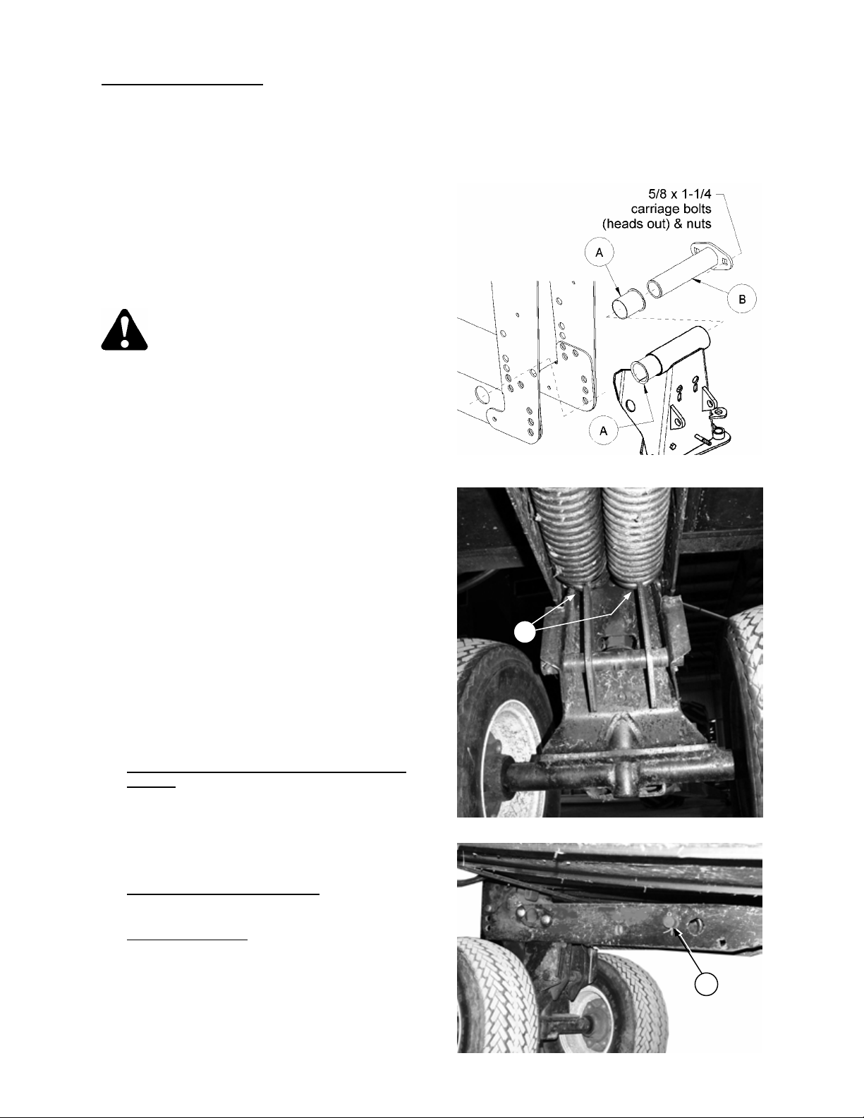
2. Identify right and left wheel supports. Left
wheel support has dual spindle.
3. Ensure plastic bush ings (A) are installed (2
per support). Position wheel assembly in
header leg and install tube (B) from right
side of header leg through wheel support.
Secure with two 5/8 x 1-1/4” carriage bolts
(heads outboard) and flange nuts.
IMPORTANT: If wheels are required for
transport only and will not be us ed in field mode
to assist header floatation or to stabilize sway,
installation of springs is not required. Leaving
the springs off makes putting the wheels into
and out of transport position easier, however
springs are required if used for floatation in f ield
mode. See “Raising Wheels to Storage
Position”, page 21.
4. Attach springs:
With 872 Combine Adapter or W indrower
Tractor: For 30’ single sickle header
install two springs at left side of header,
one spring at right side. For 30’ double
sickle or 36’ headers, install two at both
sides (an extra spri ng is prov ided with thes e
headers).
With 873 Combine Adapter
spring at each side.
L/H Wheel Support
anchor (C) at wheel support, then attach
front end of springs to header leg with pin
(D). Secure with cotter pins.
: Engage spring hook s in
: Install one
TRANSPORT OPTION
NOTE: Tube (B) is designed to be a press-fit
into leg. Use a hamm er or the hardware to fully
engage tube into leg (with flange on tube flush to
leg).
ATTACH SPRINGS – L/H SHOWN
INSTALL WHEEL SUPPORTS
C
D
Form # 46581 Issue 11/04
Page 4
3
OUTBOARD SIDE
–
INBOARD INSTALLATI
ON –
972
ONLY
TRANSPORT OPTION
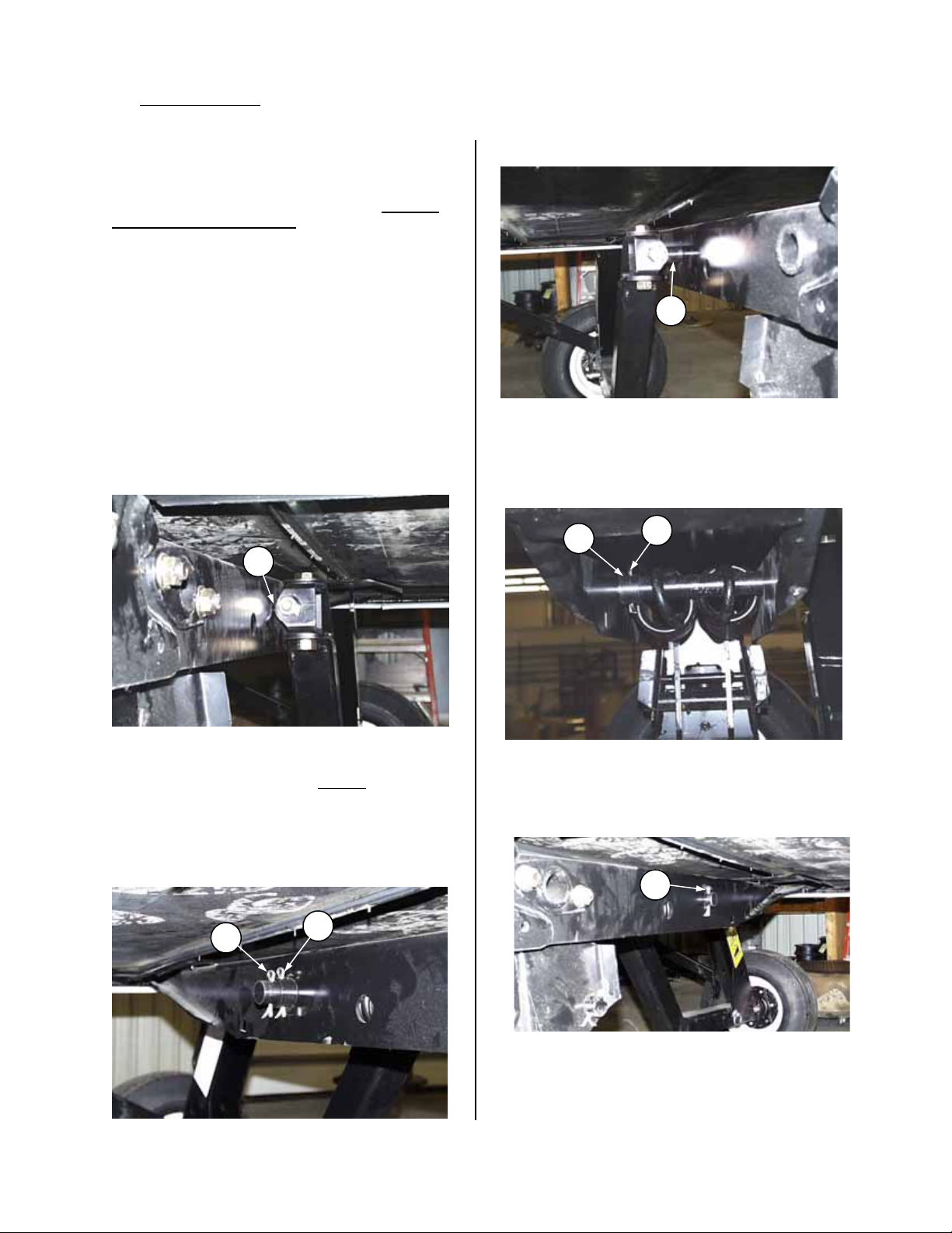
5. R/H Wheel Support:
a. Engage spring hook(s) in anchor at wheel
support same as L/H side shown in Step 4.
Attach front end of spring(s) and trans-axle
assembly to header R/H leg as follows:
NOTE: The trans-axle can be installed on inboard or
outboard side of leg for 972 or 973 headers, but must
be outboard on 974 Headers. This determines the
side of the leg where the trans-axle wheel will be
placed in storage. For headers with R/H decks that can
be split for end delivery, choose the side that places the
working wheel away from the windrow delivery
opening.
IMPORTANT: For 973/974 headers, spacer (E) for
transaxle is not used. Install 33mm ID x 57mm OD
flat washer provided in kit instead. For both
inboard (973) and outboard (973/974) installations,
position washer on outside of leg with one cotter
pin inside leg and one outside.
For installation outboard of header leg - 972:
b. Knuckle (A) must be tight against face of header
leg when trans-axle is mounted on outboard
side of header leg.
For installation inboard of header leg – 972:
d. Space knuckle away from leg as at (D) when
installing on inboard side of header leg.
D
VIEW FROM REAR OF HEADER – INBOARD SIDE
- INBOARD INSTALLATION – 972 ONLY
e. Install spacer (E) against inside face of header
leg to maintain knuckle spacing away from other
face of header leg. Install cotter pin (G).
A
VIEW FROM REAR OF HEADER –
OUTBOARD SIDE – OUTBOARD INSTALLATION
c. Install cotter pin (B) through second hole from
end of pivot shaft and through spacer to hold
knuckle against other face of header leg. Store
second cotter pin (C) in outer hole of pivot shaft.
NOTE: Assembly of knuckle away from face of
leg will result in excessive “toe-in” of R/H wheel
located underneath cutterbar.
C
B
E
G
VIEW FROM FRONT OF HEADER – INSIDE LEG
- INBOARD INSTALLATION – 972 ONLY
f. Install cotter pin (F) through last hole in pivot
shaft on outboard side of leg.
F
VIEW FROM REAR OF HEADER – INBOARD SIDE
Form # 46581 Issue 11/04
VIEW FROM REAR OF HEADER –
OUTBOARD INSTALLATION – 972 ONLY
Page 5
TRANSPORT OPTION
4
H G
H
G
BOLT POSITION 14
ABOVE CUTTERBAR.
BOLT POSITION 10
DIRECTION OF TRAVEL
SET-UP INSTRUCTIONS
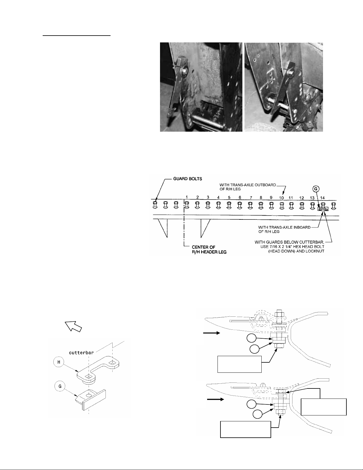
6. Install trans-axle storage latch at
right header leg. Install on same
side of leg as trans-axle. See Step
5. Engage top leg of torsion spring
on edge of header leg as shown.
NOTE: Step 7 is for 972 and 973
Headers only – Not required for 974 Header.
7. Install anchor (G) for diagonal brace under
cutter bar.
For trans-axle positioned
inboard of R/H leg: Install
anchor at 14
th
guard bolt inboard
of center of R/H header leg.
For trans-axle positioned
outboard of R/H leg: Install
anchor at 10
th
guard bolt inboard
of center of R/H header leg.
NOTE: For applications where
the sickle guards are in stalled
above the cutterbar, install
anchor spacer (H) and special
hardware as shown. For
applications where guards are
below cutterbar, use 7/16 x 2 ¼ hex head
bolt (head down) and locknut. Spacer (H)
and special hardware are not used with
guards below cutterbar.
TRANS-AXLE INBOARD OF
HEADER LEG. GUARDS
TRANS-AXLE OUTBOARD
OF HEADER LEG. GUARDS
ABOVE CUTTERBAR.
TRANS-AXLE INBOARD TRANS-AXLE OUTBOARD
STEP 6: INSTALL STORAGE LATCH
INSTALL BRACE ANCHOR AT CUTTERBAR
7/16 x 3” BOLT,
HEAD DOWN
TWO 7/16” I.D.
FLATWASHERS
Form # 46581 Issue 11/04
7/16 x 2 ¼” BOLT,
HEAD UP
Page 6
TRANSPORT OPTION
5
STEP 8:
SET-UP INSTRUCTIONS
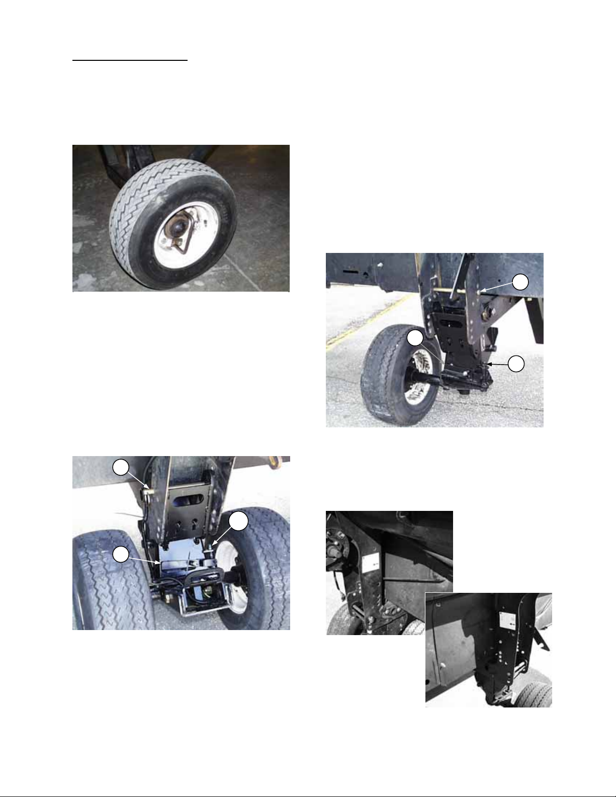
8. Attach the four gauge wheels to hubs.
Torque wheel bolts to 80 to 90 ft. lbs. (110 to
120 N·m). Use the two longer wheel bolts
(9/16 NF x 1 ½”) t o bolt handle to trans-axle
wheel.
HANDLE BOLTS TO TRANS- AX LE W H EEL
9. At L/H support, install upper pin (A) in
desired stubble height position and secure
with split ring. When header is lowered,
spring-loaded brack et will engage upper pin
as shown below.
Push down on handle (B) and lock under
welded bolt head to raise pin (C) to allow
wheel to pivot. Pivot whee l to field position.
Release handle (B) fr om under bolt head to
lower pin (C) and lock in field position.
A
C
B
L/H WHEEL SUPPORT: FIELD POSITION
10. At R/H support, install upper pin (D) in
desired stubble height position and secure
with split ring. When header is lowered,
spring-loaded brack et will engag e upper pin .
Push down on handle (F) and lock under
welded bolt head to raise pin (G) to allow
wheel to pivot. Pivot wheel to desired field
position. Releas e handle (F) from under bolt
head to lower pin (G) and lock in field
position.
NOTE: Wheel can be positioned on either
side of support, depending on delivery
opening position. (See Step 5.)
D
F
G
R/H WHEEL SUPPORT: FIELD POSITION
NOTE: Install the two decals provided on the
inboard face of left and right frame legs as
shown below. The decals indicate proper pin
position for storage, different levels of stubble
height, and transport.
DECAL PLACEMENT
LEFT FRAME LEG
DECAL PLACEMENT
RIGHT FRAME LEG
Form # 46581 Issue 11/04
Page 7
TRANSPORT OPTION
6
STEP 11:
PLACE R/H WHEEL IN ST OR AG E
SET-UP INSTRUCTIONS
11. Roll the trans-ax le to the rear of the header.
Lift and engage head of hitch pin ( C) in notch
of storage latch.
12. Lower header onto gauge wheels.
13. Check tire pressure. Inflate to 100 psi (690
kPa).
14. Place hitch in storage on back tube: At left
endsheet, install stor age s upport ( D) with ½ x
1 short neck carriage bolt and flange lock
nut.
NOTE: Orient support (D) for best clearance
of tow pole to header hoses, etc. in storage.
Lay hitch clevis over s torage support (D ) and
secure with hitch pin and lynch pin. At
inboard end, attach s upport (E) to header lef t
leg with two ½ x 1 carr iage bolts and flange
nuts. Rest hitch in support (E). Secure hitch
chain and electrical har ness at brack et (F) as
shown. Use the lock ing device on hitch cha in
to secure the hook.
C
D
STEP 14: HITCH STORAGE AT ENDSHEET
F
E
STEP 14: CHAIN & HARNESS STORAGE
STEP 14: HITCH STORAGE AT LEG
Form # 46581 Issue 11/04
Page 8
TRANSPORT OPTION
7
STEP 15:
END VIEW
STEP 15:
SET-UP INSTRUCTIONS
15. 972 Headers: Store diago nal brace on back
tube: Install diagonal brace storage bracket
(G) at right end of channel under header back
tube using one 3/8 x 1 carriage bolt and
flange lock nut.
NOTE: Use lower hole in bracket (G) to
mount on 36’ 972 Headers. For 30’ 972
Headers, use top hole to lower bracket
sufficiently to allow installation of diagonal
brace. (Crop lifter storage bracket (H) is not
present on all headers.)
Place diagonal brace ( K) in brack et as sho wn
below and insert J-bar (J) through slots in
bracket (G) and diagona l brace. Sec ure J-bar
with lynch pin as shown. For 972 headers
with 973 style cutterbar po l y s k ids, us e lon ger
J-bar provided in poly kit.
DIAGONAL BRACE & J-BAR STORAGE - 972
973 Headers: Store diago nal brace (K) in slo ts
provided in right frame leg. Insert J-bar (J) in
slot in diagonal brace and secure with lynch
pin. For 973 Headers with cutterbar poly skids,
use the longer J-bar provided in poly kit.
974 Headers: Store diago nal brace (K) in slo ts
provided in right frame leg. Install clevis pin
and split ring at (L).
G
J
K
H
G
STEP 15:
STORAGE BRACKET FOR BRACE - 972
DIAGONAL BRACE & J-BAR STORAGE - 972
K
J
K
STEP 15: DIAGONAL BRACE STORAGE – 974
Form # 46581 Issue 11/04
L
STEP 15: DIAGONAL BRACE STORAGE – 973
Page 9

TRANSPORT OPTION
8
STEP 16: ROUTE HEADER HARNESS
SET-UP INSTRUCTIONS
16. Route header wiring harness as follows:
• Route the harness from the outboard L/H
header leg up and through space between the
back sheet and the he ader back tube. Route t he
harness with the lines along front of tube and
back into the inboard L/H header leg at (Z).
Attach ground wire (M) with 1/4 x 1/2 inch hex
head bolt and flange nut. Continue routing
harness through back tube to R/H end.
NOTE: Cable tie harness to existing hydraulic
lines running along the front of back tube.
Z
P
T
M
• Secure harness at the outboard L/H header
leg with harness clip at (P). Pl ace other clip s
for best appearance. S ecur e with cab le tie at
(T), leaving 24” (610 mm) of harness from
bottom of header leg to connector. After
installing hitch for the first time, swing wheel
W
assembly to simulate 90º turns left and right.
Ensure adequate harness slack and install
cable ties at (W).
17. At the R/H end sheet, install lamp module and support as follows: For Single Sickle Headers
(N) with the hardware that secures the sickle storage tube. For Double Sickle Headers
clamp (V).
V
N
STEP 17: INSTALL LAMP MODULE – Double Sickle STEP 17: INSTALL LAMP MODULE – Single Sickle
18. Connect header harness and end sheet harness to
lamp module. Route end s heet harness to top of end
sheet through hole at reel support arm anchor (S).
19. Instal l lights at R/H end sh eet using the hard ware that
secures the pivoting amber lights. Secure harness
R
with plastic tie at (R).
, install at
, install at
S
Form # 46581 Issue 11/04
STEP 19: INSTALL LIGHTS AT END SHEET
Page 10

TRANSPORT OPTION
9
SET-UP INSTRUCTIONS
20. Install lights at R/H reel support arm using
1/2 x 1 inch carriage bolts and flange nuts
as shown.
NOTE: For headers with floating divider
option, a different light mounting bracket is
required. See instructions packaged with
dividers.
21. Install harness guard as shown at (A).
22. For 972 Headers:
Install harness guard
holder (G) on reel arm as shown. Secure
holder with 5/8 x 1 inch hex head bolt and
lock nut.
23. Route harness up inside reel support arm
and over bolt (D). Pass harness through
guard to lights and make the connections.
Secure harness with plastic tie at (C) (see
inset, top photo).
NOTE: Wire colors do not match up when
connecting harness to lights. Refer to wiring
schematic on page 10.
24. For 972 single sickle drive headers:
Attach
Slow Moving Vehicle sign to R/H endsheet
with spacer (between sign and endsheet), 3/8
x 1 ¾ carriage bolt an d flange nut as shown
below left.
For 972 double sickle drive headers
: If not
present, drill a 0.406” hole in R/H reel
support arm located 7 ½” (190 mm)
rearward of reel lif t cylinder pin (F), and 3/8”
(10 mm) above center -li ne of r eel lif t cylinder
pin (F). Attach sign to reel arm with spacer
(between sign and arm ), 3/8 x 1 ¾ carriage
bolt and flange nut as shown below center at
(E).
For 973 & 974 headers:
Attach Slow Moving Vehicle sign to R/H reel support arm with spacer
(between sign and arm), 3/8 x 1 ¾ carriage bolt and flange nut as shown below right. For these
headers, harness guard holder (G) is not used. Position harness guard above SMV hardware to
secure back end.
A
INSTALL LIGHTS & HARNESS GUARD AT
R/H REEL ARM
D
INSTALL GUARD HOLDER - 972
C
G
E
F
972 SINGLE SICKLE DRIVE 972 DOUBLE SICKLE DRIVE 973 / 974 HEADERS
INSTALL SMV SIGN
Form # 46581 Issue 11/04
Page 11

10
ELECTRICAL SCHEMATIC
TRANSPORT OPTION
Form # 46581 Issue 11/04
Page 12

TRANSPORT OPTION
11
CONVERTING FROM FIELD POSITION
TO TRANS P O R T
WARNING: To avoid injury or
caused by machine tip-o ver, move
reel fore-aft position to stabilize
the load on the tw o rear wheels in
transport. Do not move reel while
machine is in transport.
1. Move reel ful ly back on support arm s unless
combine adapter is ins talle d in h eader *. Se e
"Reel Position - Fore & Aft" in Header
Operator’s Manual for adjustment details.
For manual for e-aft: To avoid bind ing, m ove
reel two positions at a time, alternating sides
so reel moves back evenly.
Lower reel. NOTE: To prevent damage to
reel support arms, do not trans port with reel
props engaged.
* IMPORTANT: If header is being
transported with combine adapt er insta l led:
• With pick up reel – Mo ve reel to a midrange fore-aft position.
• With bat reel – Move reel further
forward.
Always check stability of load before
transporting. The rear wheels should be
carrying approximately the same weight.
2. Fully retract center link between header and
adapter.
3. Raise header fully.
DANGER: To avoid bodily injury or
death from unexpected start-up or
fall of raised header, stop engine,
remove key and engage header lift
cylinder stops before going under
header for any reason.
4. Engage float lockout on combine adapter.
See Adapter Operator’s Manual.
NOTE: Steps 5 to 9 are for 974 Flex Header
only.
5. Move all four wing float lockout pins to
“lockout” position (E). To move pins from
“float engaged” position (F) to position (E),
see “974 Flex Header: Wing Float Set-Up
and Pre-Delivery Check” in Unloading and
Assembly section of Header Operator’s
Manual.
NOTE: Steps 6 to 9 are intended to increase
ground clearance in transp ort. If you desire more
than 300 mm (12”) clearanc e under the com bine
adapter when transporting , proceed with s teps 6
to 9. Otherwise, go to step 10.
6. Place two 250 mm (10”) blocks (A) under
center section of cutterbar as shown below.
7. Lower header onto blocks.
8. At left and r ight bel lcrank , inst all clev is pin (B)
into the transport position (through the bell
crank top link) as shown and secure with
hairpin. This locks the header in the “frown”
position.
9. Raise header full y, engage lift cylinder stops
and proceed to step 10.
E
B
F
• LOCK OUT WING FLOAT – 974 HEADER
• LOCK HEADER INTO FROWN POSITION
FOR INCREASED GROUND CLEARANCE
IN TRANSPORT
A
974 HEADER - BLOCK CENTER SECTION
OF CUTTERBAR
Form # 46581 Issue 11/04
Page 13

TRANSPORT OPTION
12
STEP 13
:
ENGAGE STRUT HOOK ON CUTTERBAR
STEP 13
: INSTALL PIN IN STRUT
STEP 12
:
RELEASE R/H WHEEL FROM STORAGE
At R/H end:
10. Disengage header lift cylinder stops and
slowly lower header until wheels are on the
ground. Continue lowering header until
upper pins are loose. Remove upper pins
(C) at left and right wheels . Pins (C) will be
installed in transport position in step 17.
11. Raise header fully.
DANGER: To avoid bodily injury or
death from unexpected start-up or fall
of raised header, stop engine, remove
key and engage header lift cylinder
stops before going under header for
any reason.
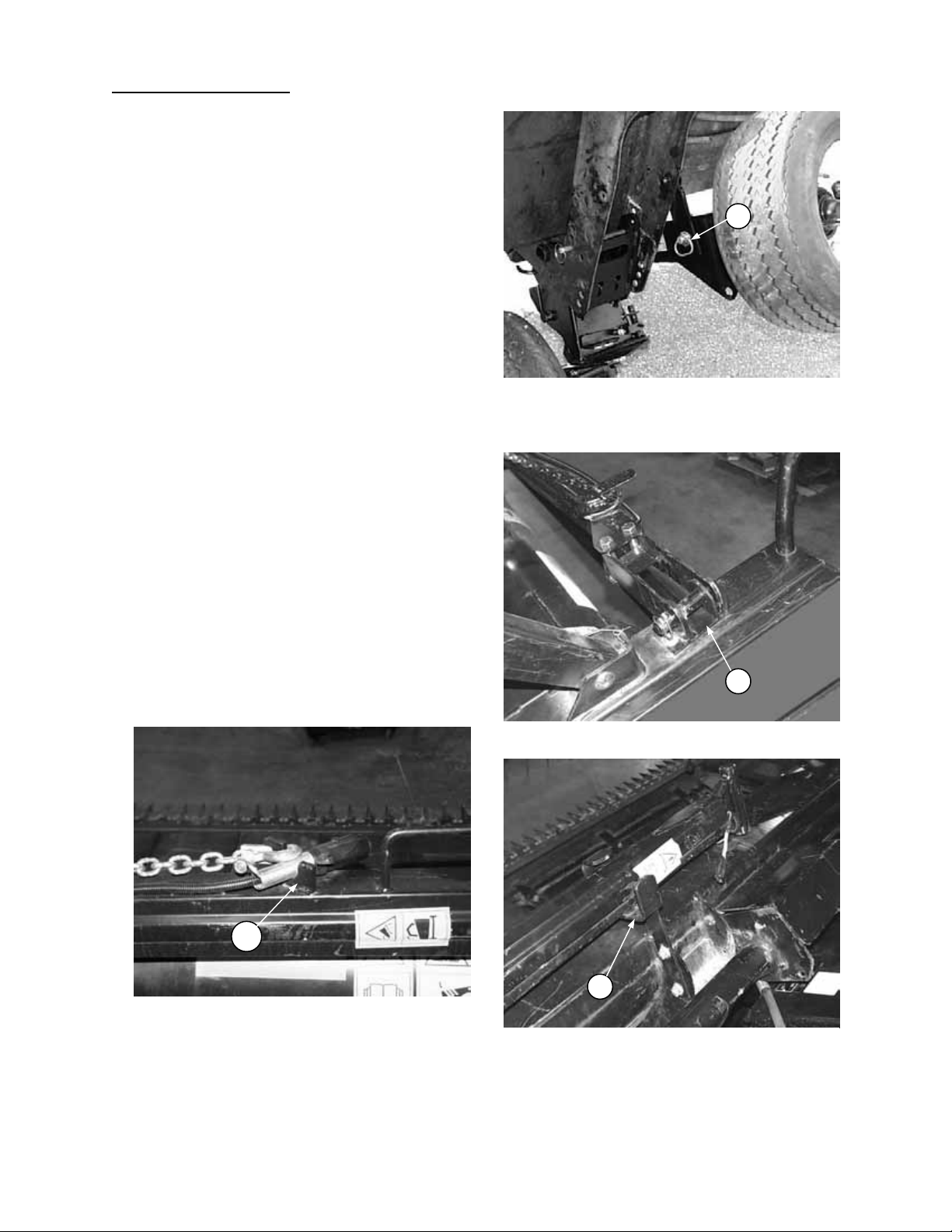
12. Lift the R/H cutterbar-side wheel to release
storage latch at (A). Roll the wheel and tr ans axle under cutterbar to transport position.
13. Remove hitch pin from strut channel. Pivot
strut channel upwards an d enga ge s tr ut ho ok
into slot on back edge of cutterbar. Install
hitch pin in transport position (B). Secure
with split ring.
NOTE: For 973 and 974 Headers with poly
wearplates on cutterbar, it will be necessary to
notch poly in two places. See page 21.
14. Remove diagonal brace from storage
position on header.
For 972 and 973 Headers: Engag e head of
brace on cutterbar anchor and rotate brace
clockwise to engage head behind the guard
trash bar.
For 974 Header: Install brace onto lug
welded to rear of cutterb ar and secur e wit h ¾
x 1-3/16 clevis pin and split ring.
C
A
B
STEP 14: ENGAGE BRACE ON LUG –
974 HEADER
Form # 46581 Issue 11/04
STEP 14: ENGAGE BRACE ON ANCHOR –
972 & 973 HEADERS
Page 14

TRANSPORT OPTION
13
STEPS 17
-
19:
POSITION R/H REAR WHEEL
CONVERTING FROM FIELD POSITION
TO TRANS P O R T
15. Engage other end of di ago nal br ac e on pin at
strut. Secure with lynch pin.
16. 972 & 9 73 Headers onl y: Hook the J-bar on
back edge of cutterbar an d through head of
diagonal brace. Secure with lynch pin. For
972 & 973 Headers with 9 73 style cutterbar
poly skids, use the longer J-bar provided in
poly kit.
17. Install pins removed in step 10 in transport
position (A), engaging the hole in spring
loaded bracket as shown in lower right photo.
Secure with split ring.
18. Raise header fully and engage lift cylinder
stops.
19. At R/H rear wheel, push down on ha ndle (F)
and lock under welded bolt head to raise p in
(G) to allow wheel to pivot. Pivot wheel to
transport position. Release handle (F) from
under bolt head t o lower pin (G) and lock in
transport position.
(continued)
A
STEP 15: SECURE BRACE TO STRUT
STEP 16: INSTALL J-BAR –
972 & 973 HEADERS
A
F
G
Form # 46581 Issue 11/04
Page 15

TRANSPORT OPTION
14
STEP 20
:
INSTALL HITCH IN SPINDLE SOCKET
STEP 23
:
STEPS 21
-
22:
CONVERTING FROM FIELD POSITION
TO TRANS P O R T
At L/H end:
20. Install hitch in socket of dual whee l spindle,
engaging hitch end-pin in channel slots.
21. Lower the top chan nel and secure with lynch
pin (A). Push do wn on handle (B) and lock
under welded bolt head to raise pin (C) to
allow wheel to piv ot. Leave han dle in lock ed
position, as the dual wheel assembly must
be free to pivot in transport.
22. Connect header wiring harness to hitch
harness at (D).
23. Swing the hitch pole around to the left end.
24. If combine adapter is to remain with the
header, ensure float lock-outs are engaged.
25. Disengage header lift cylinder stops and
slowly lower header until wheels are on the
ground. Block the tires to prevent header
rolling.
26. Detach header from power unit. See
Windrower Tractor or Combine Adapter
Operator's Manual. Be sure reel is fully
down and all hydraulic lines are properly
disconnected and stored.
WARNING: For headers with
hydraulic reel fore-aft, never
connect the fore-aft couplers to
each other. This would complete
the circuit and allow th e reel to creep f orward
in transport, resulting in instability.
(continued)
C
B
A
D
L/H DUAL WHEELS – TRANSPORT POSITION
SWING HI TC H TO TR ANSPORT POSITI O N
Form # 46581 Issue 11/04
Page 16

TRANSPORT OPTION
15
ATTACHING TO TOWING VEHICLE
CAUTION: To avoid bodily injury and/or machine damage caused by loss of control:
1. To ensure adequate braking performance and control, do not tow with a vehicle weighing less
than 5000 lbs. (2300 kg).
2. To increase header stability in transport, ensure th at reel is down and fully back on support
arms. For headers with hydraulic reel fore-aft, never connect the fore-aft couplers to each
other. This would complete the circuit and allow the reel to creep forward in transport,
resulting in instability.
3. Check that all pins are properly secured in transport position at wheel supports, hitch and
cutterbar support.
4. Check tire condition and pressure prior to transporting.
5. Connect hitch to towing vehicle with a proper hitch pin with a spring locking pin or other
suitable fastener.
6. At tach hitch chain to tow ing vehicle. Adjust chain length to r emove all slack except what is
needed for turns.
7. Connect header wiring harness 7-pole plug to mating receptacle on towing vehicle. (The 7-pole
receptacle is available from your dealer parts department.)
8. Ensure lights are functioning properly, and clean the slow moving vehicle emblem and other
reflectors.
TOWING THE HEADER
CAUTION: THIS IS INTENDED AS A LOW SPEED TRANSPORT. To avoid bodil y injury
and or machine damage caused by loss of control:
1. Do not exceed 20 mph (30 km/h). Reduce transport speed for slippery or rough conditions.
2. Turn corners only at very low speeds [5 mph (8 km/h) or less]. While cornering, header
stability is reduced as front wheel moves to the left.
3. Obey all highway traffic regulations in your area when transporting on public roads. Use
flashing amber lights unless prohibited by law.
Form # 46581 Issue 11/04
Page 17

TRANSPORT OPTION
16
J STEP 6:
L/H DUAL WHEELS
–
FIELD POSITION
CONVERTING FROM TRANSPORT TO
FIELD POSITION
1. Block the tires to prevent header rolling.
2. Attach header to power unit.
See Windrower Tr actor or Combine Adap ter
Operator Manual.
3. Raise header fully.
4. Swing the hitch pole around to the back of
the header. Detach header wiring harness
from hitch harness at 4-way connector (A).
Wrap header harness around lynch pin
locking bracket (C) once hitch is removed.
5. Remove lynch pin (B), raise the top channe l
and remove hitch f rom socket of dual wheel
spindle.
6. At L/H support, install upper pin (D) in
desired stubble height position and secure
with split ring. When header is lowered,
spring-loaded brack et will engage upper pin
as shown.
Release handle (E) fr om under bolt head to
lower pin (F) and lock in field position.
NOTE: If cutting low to the groun d an d no g au ge
wheel contact is desired , wheels can be raised
to storage position. See page 21.
At R/H end
:
7. 972 & 973 Headers: Det ach J-bar (J ) which
locks diagonal brace to cutterbar.
974 Header: Remove split ring and clevis pin
(K) securing diagonal brace to lug at rear of
cutterbar.
DANGER: To avoid bodily injury or
death from unexpected start-up or
fall of raised header, stop engine,
remove key and engage header lift
cylinder stops before going under
header for any reason.
K
B
A
STEP 5: DETACH HITCH
D
F
E
C
STEP 7: REMOVE CLEVIS PIN FROM LUG –
Form # 46581 Issue 11/04
STEP 7: DETACH J-BAR – 972 & 973 HEADER
974 HEADER
Page 18

TRANSPORT OPTION
17
STEP 8: DETACH BRACE FR OM STR UT
& REMOVE PIN
CONVERTING FROM TRANSPORT TO
FIELD POSITION
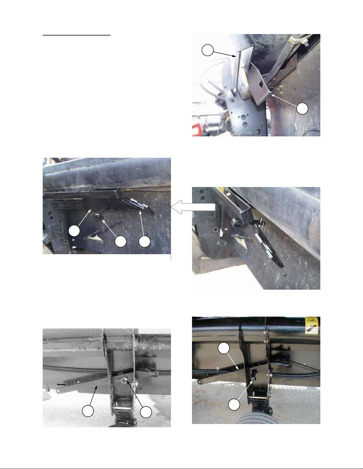
8. Detach diagonal brace from s trut channel at
(A) and remove brace head from cutterbar.
Remove pin (B) from transport position.
9. Disengage strut hook from cutterbar and
pivot strut channel down to collapsed
position on the trans-axle. Install pin (B) in
storage position (through hole D in above
photo) and secure with split ring.
NOTE: Install pin so head is on correct side
for storage of trans-axle wheel. See Step 11.
10. At R/H support, install upper pin (D) in
desired stubble height position and secure
with split ring. When header is lowered,
spring-loaded brack et will engag e upper pin .
Push down on handle (F) and lock under
welded bolt head to raise pin (G) to allow
wheel to pivot. Pivot wheel to desired field
position. Release handle (F) f rom under bolt
head to lower pin (G) and lock in field
position.
NOTE: Wheel can be positioned on either
side of support, depending on delivery
opening position.
(continued)
D
B
STEP 9: DETACH STRUT HOOK
F
A
D
G
Form # 46581 Issue 11/04
STEP 10: R/H FIELD WHEEL
Page 19

TRANSPORT OPTION
18
STEP 11:
TRANS
-
AXLE WHEEL STORAGE
CONVERTING FROM TRANSPORT TO
FIELD POSITION
11. Roll the trans-axle to the r ear of the header.
Lift and engage head of hitch pin (C) in
notch of storage latch.
NOTE: Trans-axle can be positioned on
either side of leg, depending on delivery
opening position.
12. Lower header to cutting height and move
reel to desired operating position. For
manual fore-af t: To avoid b inding, m ove reel
two positions at a time, alt ernating sides so
reel moves back evenly.
13. Place hitch in storage on back tube: At left
endsheet, lay hitch clevis over storage
support (D) and secure with hitch pin and
lynch pin. At inboard end, rest hitch in
support (E). Secure hitch chain and
electrical harness at bracket (F) as shown.
Use the locking device on hitch chain to
secure the hook.
STEP 13: CHAIN & HARNESS STORAGE
(continued)
F
C
D
STEP 13: HITCH STORAGE AT ENDSHEET
Form # 46581 Issue 11/04
E
STEP 13: HITCH STORAGE AT LEG
Page 20

TRANSPORT OPTION
19
STEP 14:
END VIEW
CONVERTING FROM TRANSPORT TO
FIELD POSITION
14. 972 Headers: Place diagonal brace (K) in
bracket (G) at right end of channel under
header back tube as s ho wn bel o w a nd inser t
J-bar (J) through slots in bracket (G) and
diagonal brace. Secure J -bar with lynch pin
as shown.
(continued)
G
J
K
973 Headers: Stor e diagonal brace (K) in slots
provided in right fr am e leg. Ins er t J- bar (J ) in s lot
in diagonal brace and secure with lynch pin.
974 Headers: Stor e diagonal brace (K) in slots
provided in right fram e leg. Install clevis pin and
split ring at (L).
DIAGONAL BRACE & J-BAR STORAGE - 972
K
J
STEP 14: DIAGONAL BRACE STORAGE – 973
K
L
STEP 14: DIAGONAL BRACE STORAGE – 974
Form # 46581 Issue 11/04
Page 21

TRANSPORT OPTION
20
CONVERTING FROM TRANSPORT TO
FIELD POSITION
15. Raise header fully.
16. Disengage flo at lockout on com bine adapter
and extend center link to desired operating
position. See Adapter Operator’s Manual.
NOTE: Remaining steps are for 974 Flex
Header only.
NOTE: If pins (B) were installed through
bellcrank top link to increase ground clearance
in transport, complete steps 17 to 20 to move
pins to storage position as follows:
17. Place two 250 mm (10”) blocks (A) under
center section of cutterbar as shown.
18. Lower header onto blocks.
19. At left and right bellcrank, retract clevis pin
(B) to the storage position as shown and
secure with hairpin.
20. Raise header and engage lift cylinder stops.
21. Move all four wing float lock out pins to “float
engaged“ position (F).
22. Disengage lift cylinder stops and lower
header.
(continued)
DANGER: To avoid bodily injury or
death from unexpected start-up or
fall of raised header, stop engine,
remove key and engage header lift
cylinder stops before going under
header for any reason.
A
974 HEADER - BLOCK CENTER SECTION
OF CUTTERBAR
B
974 HEADER – MOVE “FROWN LOCK” PINS
TO STORAGE POSITION
F
974 HEADER –
DISENGAGE WING FLOAT LOCKOUT
Form # 46581 Issue 11/04
Page 22

TRANSPORT OPTION
21
POLY
WEARPLATE MODIFICATION
FOR 973 & 974 HEADERS
as a guide to notch poly
RAISING WHEELS TO STORAGE POSITION
If cutting low to the ground and no gauge wheel
contact is desired, wheels can be raised to
storage position, as follows:
• Raise header fully.
DANGER: To avoid bodily injury or
death from unexpected s tart-up or
fall of raised header, stop engine,
remove key and engage header lift
cylinder stops before going under
header for any reason.
• If springs were removed f rom wheels, simply
raise wheel support b y hand and install pin
in storage position, b oth sides. If springs are
installed, proceed as follows:
• Place 10” (250 mm) blocks under L/H and
R/H gauge wheels as shown.
• Lower header until cutterbar touches
ground.
• Place pins (D) into storage location to lock
wheels in raised position.
• Raise header and remove blocks.
NOTE: When converting to transport position
when wheels are in s torage as above, it will be
necessary to block wheels as shown to allow
removal of pin (D) (if springs are installed).
POLY WEARPLATE MODIFICATION FOR
973 & 974 HEADERS
For 973 and 974 Headers with poly wearplates
on cutterbar, it will be nece ssar y to notch poly in
two places.
At R/H outer leg, notch poly wearplate assembly
(K) and poly skid shoe (L) as shown below.
NOTE: Notches are required for clearance for
trans-axle strut hook where it engages the
cutterbar in transport.
Trim poly skid
shoe as shown
D
BLOCK WHEELS TO MOVE PIN TO
STORAGE POSITION
L
Use notch in steel wearplate
Form # 46581 Issue 11/04
77 mm (3”)
77 mm (3”)
40 mm (1-9/16”)
K
Page 23

TRANSPORT OPTION
22
MAINTENANCE / SERVICE
100 Hour or Annual Greasing
Wheel Support Pivots (A) – four fittings
(2 per wheel support)
500 Hour or Annual Greasing
Wheel Hub Bearings (B) – one fitting per wheel
WHEEL SUPPORT PIVOTS
A
B
WHEEL HUB BEARINGS
Form # 46581 Issue 11/04
Page 24

TRANSPORT OPTION
23
MAINTENANCE / SERVICE
Wheel Bolts
Check and tighten wheel bolts after the first 10
hours of operation and every 100 hours
thereafter.
Whenever a wheel is rem oved and re-installed,
check torque after one hour of operation.
Maintain torque of 80 to 90 ft.lbs. (110 to 120
N⋅m)
Follow the proper bolt tightening sequence
shown.
NOTE: When installing wheel, be sure valve
stem (C) points away from wheel support.
Tire Inflation
Check tire pressure dai ly
kPa).
beyond 35 psi (241 kPa) to seat the bead on
the rim. Replace the tire if it has a defect.
Replace a wheel rim, which has cracks, w ear
or severe rust. Never w eld a wheel rim. M ake
sure all the air is remo ved from a tire befor e
removing the tire from a rim. Nev er use force
on an inflated or partially inflated tire. Make
sure the tire is correctly seated before
inflating to operating pressure.
Do not remove, install or make repairs to a
tire on a rim unless you have the proper
equipment and experience to perform the
job. Take the tire and rim to a qualified tire
repair shop. If the tire is not in correct
position on the rim, or is too full of air, the
tire bead can loosen on one side, causing air
to leak at high speed and wit h great f orce. An
air leak of this nature can thrust the tire in
any direction, endangering anyone in the
area.
(A) - Use a safety cage if available.
(B) - Do not stand over tire. Use a clip-on chuck
and extension hose.
. Maintain 100 psi (6 90
WARNING: Service tires safely. A
tire can explode during inflation
and cause serious injur y or death.
Never increase air pressure
1
C
3
6
5
4
2
BOLT TIGHTENING SEQUENCE
SERVICE TIRE S SAFELY
Form # 46581 Issue 11/04
 Loading...