

Page 1

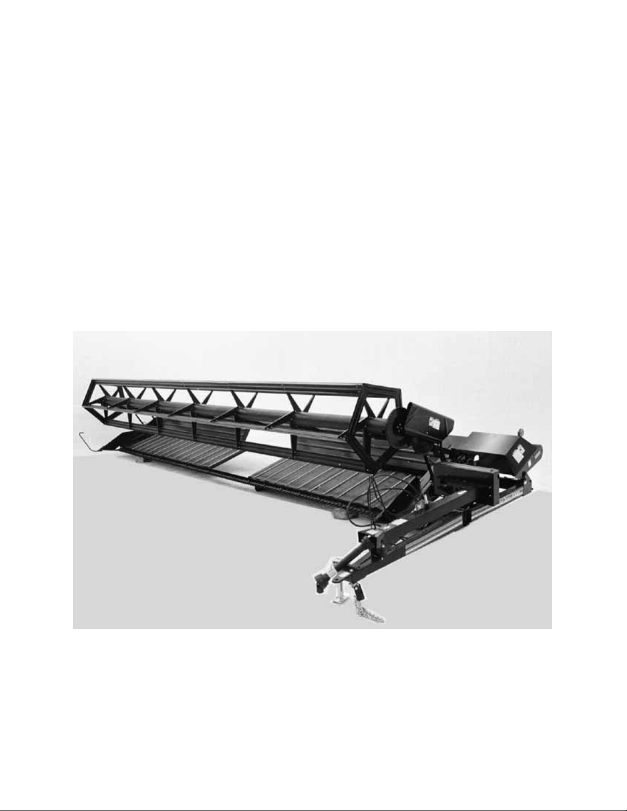
Model 3020
PULL-TYPE
WINDROWER
OPERATOR’S MANUAL
Form 147021 Issue 06/03
Sugg. Retail: $15.00
Page 2
INTRODUCTION
Your new Pull-Type Windrower is designed to cut, and lay in windrows, a wide variety of grain and specialty
crops. Windrowing allows starting the harvest earlier, protects the crop from wind damage, and gives you more
flexibility in scheduling combine time.
Use this manual as your first source of information about the machine. If you follow the instructions given in
this manual, your Windrower will work well for many years.
The manual contains instructions for "Safety", "Operation", and "Maintenance/Service". A separate booklet
provides information on "Unloading and Assembly".
CAREFULLY READ ALL THE MATERIAL PROVIDED BEFORE ATTEMPTING TO UNLOAD, ASSEMBLE,
OR USE THE MACHINE.
Use the Table of Contents and the Index to guide you to specific areas. Study the Table of Contents to
familiarize yourself with how the material is organized.
Keep this manual handy for frequent reference and to pass on to new operators or owners. Call your Dealer if
you need assistance, information, or additional copies of this manual.
NOTE: Right hand (R/H) and left hand (L/H) designations are determined from the operator's position, facing
forward.
i
Page 3

TABLE OF CONTENTS
PAGE
INTRODUCTION................................................................................................................................... i
SERIAL NUMBER LOCATION .............................................................................................................v
SAFETY
Safety Alert Symbol......................................................................................................................... vi
Signal Words................................................................................................................................... vi
Safety Signs.................................................................................................................................vii, viii
General Farm Safety..................................................................................................................... ix, x
SPECIFICATIONS
Windrower........................................................................................................................................1
Tractor Requirements ......................................................................................................................1
Hardware Torque Specifications......................................................................................................2
Hydraulic Fitting Torque Specifications............................................................................................3
OPERATION
Your Responsibilities as an Owner/Operator...................................................................................4
To the New Operator........................................................................................................................4
Preparing the Tractor ..................................................................................................................... 5,6
Preparing the Windrower ...............................................................................................................7,8
Attaching Windrower to Tractor..................................................................................................... 9,10
Detaching Windrower from Tractor .............................................................................................. 11,12
Break-In Period ...............................................................................................................................13
Pre-Starting Checks: Annual...........................................................................................................14
Pre-Starting Checks: Daily..............................................................................................................15
Operate Correctly............................................................................................................................16
Engaging the PTO...........................................................................................................................17
Cutting Width...................................................................................................................................17
Right Hand Divider Rod ..................................................................................................................17
Header Lock....................................................................................................................................18
Cutting Height (minimum header height adjustment)......................................................................18
Ground Speed.................................................................................................................................19
Reel Speed .....................................................................................................................................20
Reel Props ......................................................................................................................................21
Reel Height .....................................................................................................................................21
Reel Position - Fore and Aft............................................................................................................22
Draper Speed..................................................................................................................................23
Delivery Opening Width ...............................................................................................................24,25
Delivery Opening Height .................................................................................................................26
Levelling the Cutterbar....................................................................................................................26
Windrow Characteristics .................................................................................................................27
Cornering ........................................................................................................................................28
Field Light........................................................................................................................................28
Unplugging the Sickle .....................................................................................................................29
Shut-Down Procedure.....................................................................................................................29
Transporting the Windrower......................................................................................................... 30,31
Transport Width...............................................................................................................................31
Converting from Field Position to Transport................................................................................. 32,33
Converting from Transport to Field Position................................................................................. 33,34
Storage Procedure..........................................................................................................................35
ii
Page 4

TABLE OF CONTENTS
PAGE
MAINTENANCE/SERVICE
Service Procedures.........................................................................................................................36
Greasing the Windrower ..............................................................................................................37-41
Telescoping Hitch Pin .....................................................................................................................42
Left Wheel Lock Assembly..............................................................................................................42
Header Flotation..............................................................................................................................42
Hydraulics ....................................................................................................................................43,44
Removal of Header Lift Cylinder .....................................................................................................44
Electrical..........................................................................................................................................45
Main Drives:
Belt Alignment...............................................................................................................................46
Idler Pulley Shield Alignment ........................................................................................................46
Belt Tension ..................................................................................................................................47
Removal of Main Drive Pulley.......................................................................................................47
Sickle and Sickle Drive:
Sickle Lubrication..........................................................................................................................48
Sickle Sections..............................................................................................................................48
Sickle Removal and Installation ....................................................................................................49
Pitman Replacement.....................................................................................................................49
Guards ..........................................................................................................................................50
Excessive Breakage......................................................................................................................50
Sickle Hold-Downs........................................................................................................................50
Sickle Register ..............................................................................................................................51
Sickle Drive Belt Tension ..............................................................................................................52
Reel and Reel Drive:
Reel Clearance from Cutterbar .....................................................................................................53
Centering the Reel ........................................................................................................................54
Reel Primary Drive Belt Tension...................................................................................................55
Reel Final Drive Belt Tension........................................................................................................55
Drapers and Draper Drive:
Draper Care ..................................................................................................................................56
Draper Tracking .........................................................................................................................56,57
Draper Tension .............................................................................................................................58
Replacing Drapers ........................................................................................................................59
Draper Drive Belts.........................................................................................................................59
Draper Drive Belt Idler Alignment..................................................................................................60
Wheels and Tires:
Wheel Bolts...................................................................................................................................61
Wheel Alignment...........................................................................................................................62
Tire Inflation ....................................................................................................................................63
Stabilizer Spring Adjustment - 36 foot Windrower...........................................................................64
Maintenance Schedule................................................................................................................. 65,66
Maintenance Record.......................................................................................................................67
iii
Page 5

TABLE OF CONTENTS
PAGE
TROUBLE SHOOTING
Windrow Formation.........................................................................................................................68
Crop Loss at Cutterbar................................................................................................................. 68,69
Crop Loss at Drapers......................................................................................................................69
Transport.........................................................................................................................................69
Drives........................................................................................................................................... 69-71
Drapers ...........................................................................................................................................71
ATTACHMENTS
PTO Conversion Kit ........................................................................................................................72
Narrow Delivery Opening Kit...........................................................................................................72
Hitch Plate Kit..................................................................................................................................72
Left Hand Divider Rod.....................................................................................................................72
UNLOADING & ASSEMBLY ................................................................................................................73
INDEX ...............................................................................................................................................74,75
iv
Page 6

SERIAL NUMBER LOCATION
Record the serial number in the space provided.
Pull Type Windrower:
Serial number plate (A) is located on the side of
the left hand end frame.
NOTE: When ordering parts and service, be sure
to give your dealer the complete and proper serial
number.
SERIAL PLATE LOCATION: WINDROWER
A
v
Page 7

SAFETY
SAFETY ALERT SYMBOL
Why is SAFETY important to you?
3 BIG REASONS · ACCIDENTS COST
SIGNAL WORDS
Note the use of the signal words DANGER, WARNING, and CAUTION with safety messages. The appropriate
signal word for each message has been selected using the following guidelines:
DANGER – Indicates an imminently hazardous situation that, if not avoided, will result in death or
serious injury.
WARNING – Indicates a potentially hazardous situation that, if not avoided, could result in death or
serious injury. It is also used to alert against unsafe practices.
CAUTION – Indicates a potentially hazardous situation that, if not avoided, may result in minor or
moderate injury. It is also used as a reminder of good safety practices.
This safety alert symbol indicates important safety messages in this
manual and on safety signs on the windrower.
This symbol means:
ATTENTION!
BECOME ALERT!
YOUR SAFETY IS INVOLVED!
Carefully read and follow the safety message accompanying this symbol.
· ACCIDENTS DISABLE AND KILL
· ACCIDENTS CAN BE AVOIDED
vi
Page 8
SAFETY
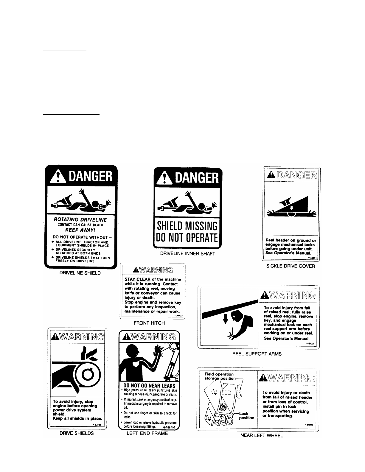
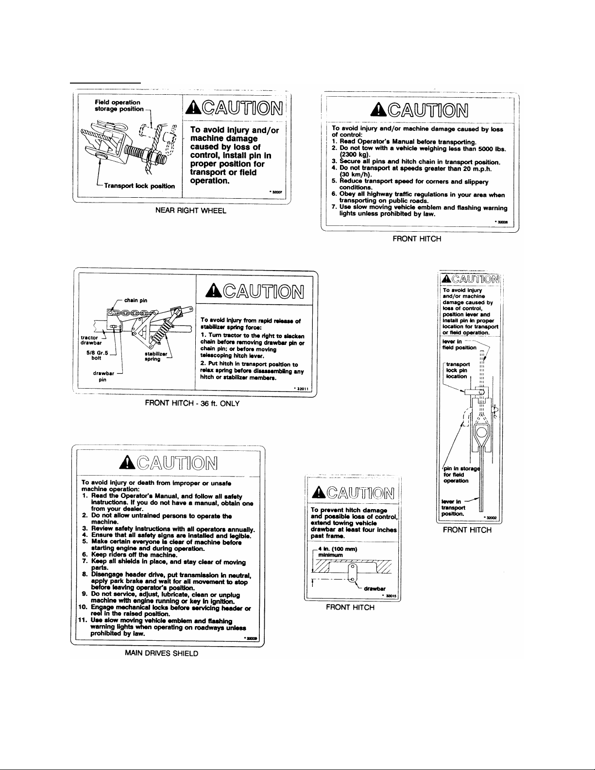
SAFETY SIGNS
• The safety signs reproduced here appear on the windrower at the locations listed.
• Keep safety signs clean and legible at all times.
• Replace safety signs that are missing or become illegible.
• If original parts on which a safety sign was installed are replaced, be sure the repair part also bears the
current safety sign.
• Safety signs are available from your Dealer Parts Department.
To install safety signs
1. Be sure the installation area is clean and dry.
2. Decide on the exact location before you remove the decal backing paper.
3. Remove the smaller portion of the split backing paper.
4. Place the sign in position and slowly peel back the remaining paper, smoothing the sign as it is applied.
5. Small air pockets can be smoothed out or pricked with a pin.
:
vii
Page 9
SAFETY
SAFETY SIGNS
(continued)
viii
Page 10
SAFETY
GENERAL SAFETY
The following are general farm safety
precautions that should be part of
your operating procedure for all
types of machinery.
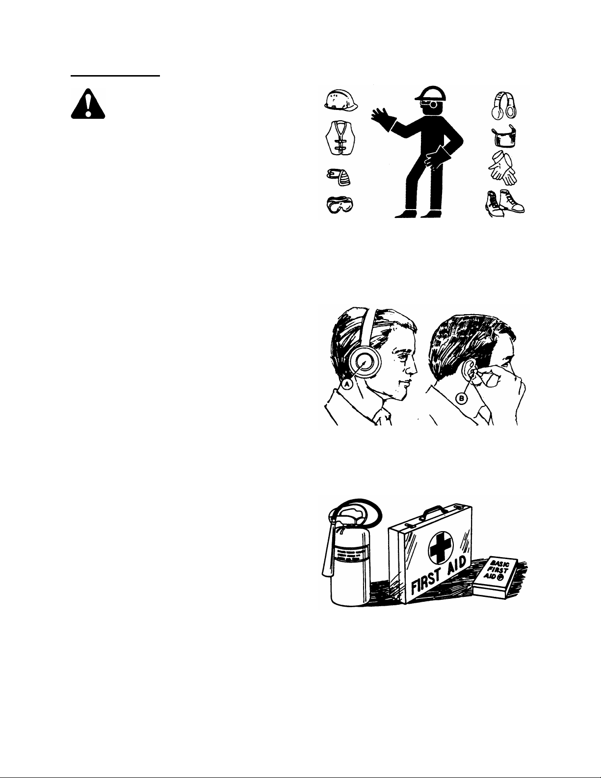
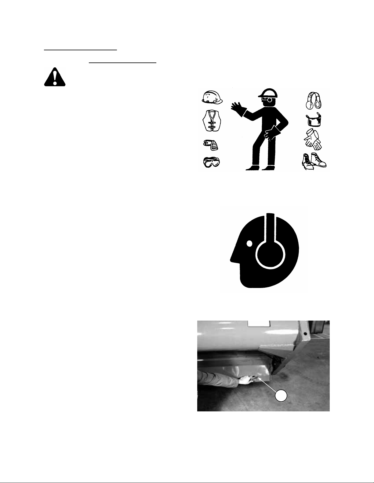
1. Protect yourself.
When assembling, operating and servicing
machinery, wear all the protective clothing
and personal safety devices that COULD be
necessary for the job at hand. Don't take
chances.
You may need:
• a hard hat.
• protective shoes with slip resistant soles.
• protective glasses or goggles.
• heavy gloves.
• wet weather gear.
• respirator or filter mask.
• hearing protection. Be aware that prolonged
exposure to loud noise can cause
impairment or loss of hearing. Wearing a
suitable hearing protective device such as
ear muffs (A) or ear plugs (B) protects
against objectionable or loud noises.
2. Provide a first-aid kit for use in case of
emergencies.
3. Keep a fire extinguisher on the machine. Be
sure the extinguisher is properly maintained
and be familiar with its proper use.
4. Keep young children away from machinery
at all times.
5. Be aware that accidents often happen
when the operator is tired or in a hurry to
get finished. Take the time to consider the
safest way. Never ignore warning signs of
fatigue.
PROTECT YOURSELF
PROTECT AGAINST NOISE
BE PREPARED FOR EMERGENCIES
ix
Page 11
SAFETY
GENERAL SAFETY
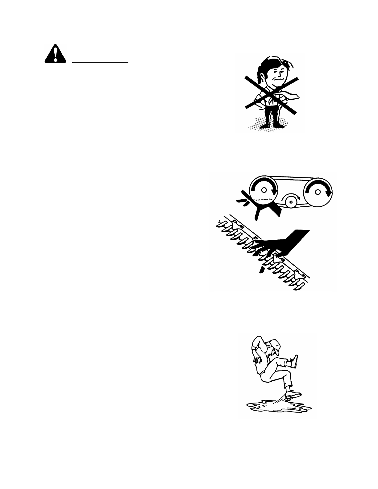
6. Wear close-fitting clothing and cover long
hair. Never wear dangling items such as
scarves or bracelets.
7. Keep hands, feet, clothing and hair away
from moving parts. Never attempt to clear
obstructions or objects from a machine
while the engine is running.
8. Keep all shields in place. Never alter or
remove safety equipment. Make sure
driveline guards can rotate independently
of the shaft and can telescope freely.
9. Use only service and repair parts made or
approved by the equipment manufacturer.
Substituted parts may not meet strength,
design, or safety requirements.
10. Do not modify the machine. Unauthorised
modifications may impair the function
and/or safety and affect machine life.
11. Stop engine and remove key from ignition
before leaving operator's seat for any
reason. A child or even a pet could engage
an idling machine.
12. Keep the area used for servicing
machinery clean and dry. Wet or oily floors
are slippery. Wet spots can be dangerous
when working with electrical equipment.
Be sure all electrical outlets and tools are
properly grounded.
13. Use adequate light for the job at hand.
14. Keep machinery clean. Straw and chaff on
a hot engine are a fire hazard. Do not allow
oil or grease to accumulate on service
platforms, ladders or controls. Clean
machines before storage.
15. Never use gasoline, naphtha or any volatile
material for cleaning purposes. These
materials may be toxic and/or flammable.
16. When storing machinery, cover sharp or
extending components to prevent injury
from accidental contact.
(continued)
NEVER WEAR LOOSE
OR DANGLING CLOTHES
KEEP AWAY FROM MOVING PARTS
KEEP SERVICE AREA CLEAN AND DRY
x
Page 12

SPECIFICATIONS
NOTE: Specifications listed only under 25 ft. column are common to all sizes, with exceptions listed under
appropriate column.
21 FT.
DIMENSIONS
Overall Width:
Transport Position 10'6" (3200 mm) 10'10" (3300 mm) 11'2" (3400 mm) 12' (3660 mm)
Field Position 25'4" (7720 mm) 29'4" (8940 mm) 34'4" (10450 mm) 40'4" (12290 mm)
Overall Length:
Transport Position 32'3" (9830 mm) 36'2" (11028 mm) 41' (12500 mm) 49'2" (14985 mm)
Field Position 13'4" (4070 mm) 13'4" (4070 mm) 13'4" (4070 mm) 15'8" (4775 mm)
Overall Height:
Transport Position 8'10" (2700 mm)
Mass 3100 lbs (1450 kg) 3400 lbs (1540 kg) 3750 lbs (1700 kg) 4500 lbs (2040 kg)
SICKLE
Drive Crank Wheel - Pitman System
Cutting Height Range 0 to 45" (0 to 1150 mm)
Stroke Length 3" (76 mm)
Speed 1250 strokes per minute
Width of Cut (nominal) 21' (6400 mm) 25' (7620 mm) 30' (9150 mm) 36' (10975 mm)
Header Lift Hydraulic (from tractor)
REEL
Type 1 x 21' 1 x 25' 1 x 30' 2 x 18'
Diameter 49.2" (1250 mm)
Lift Range (above cutterbar) 1 to 28.5" (25 to 725 mm)
Speed 27 to 50 RPM
Lift Hydraulic (from tractor)
DRAPERS & DELIVERY OPENING
Width 41.5" (1054 mm)
Speed 275 to 480 ft./min. (84 to 146 m/min.)
Angle (at 6" cutting height) 16° at standard frame height
21° at raised frame height
Delivery Opening Widths 45.5" (1155 mm) 53.0" (1345 mm)
(between rollers) 53.0" (1345 mm) 60.8" (1545 mm)
60.5" (1535 mm) 68.7" (1745 mm)
76.6" (1945 mm)
Delivery Opening Height 33.5” (850 mm) at standard frame height
38.6” (980 mm) at raised frame height
TIRES
Size 9.5L - 14I1 Rib Implement
Pressure 24 to 28 psi (165 to 190 kPa)
DRIVES
Sickle Mechanical
Reel Mechanical
Drapers Mechanical
TRACTOR REQUIREMENTS
Minimum Weight 5000 lbs. (2270 kg) 6000 lbs. (2720 kg)
Minimum Power 40 hp (30 kw) 50 hp (38 kw)
PTO Speed 540 or 1000
Hydraulics Dual
Minimum Pressure 1800 psi (12400 kPa)
25 FT. 30 FT. 36 FT.
1
Page 13
TORQUE SPECIFICATIONS
[
[
]
[.4]
[
]
[
[
]
[4]
[7]
[7]
[11]
[18]
[26]
[37]
[52]
[66]
[92]
[
[
]
[
[
]
[
[
]
[
[
]
[
[
]
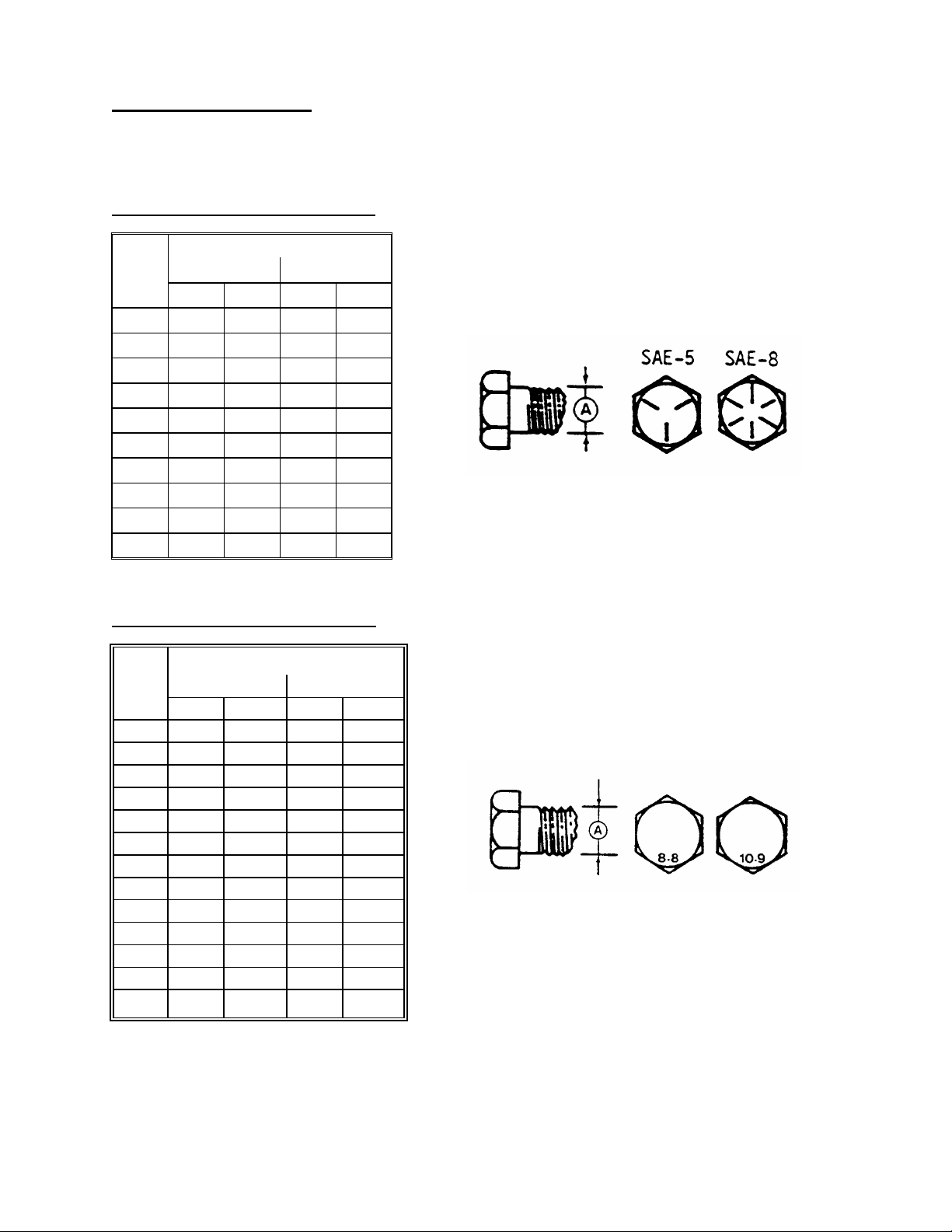
CHECKING BOLT TORQUE
The tables shown below give correct torque values for various bolts and capscrews. Tighten all bolts to the
torques specified in chart unless otherwise noted throughout this manual. Check tightness of bolts periodically,
using bolt torque chart as a guide. Replace hardware with the same strength bolt.
ENGLISH TORQUE SPECIFICATION
Bolt
Dia.
"A"
1/4" 12 [9] 15 [11]
5/16" 24 [18] 34 [25]
3/8" 43 [32] 56 [41]
7/16" 68 [50] 95 [70]
1/2" 102 [75] 142 [105]
9/16" 149 [110] 202 [149]
5/8" 203 [150] 271 [200]
3/4"
7/8" 569 [420] 813 [600]
1" 867 [640] 1205 [890]
METRIC TORQUE SPECIFICATIONS
Bolt
Dia.
"A"
M3 0.5
M4
M5
M6
M8
M10 50
M12 90
M14 140
M16 225
M20 435
M24 750
M30 1495
M36 2600 [1917] 3675 [2710]
Torque figures indicated above are valid for non-greased or non-oiled threads and heads unless otherwise
specified. Do not grease or oil bolts or capscrews unless specified in this manual. When using locking
elements, increase torque values by 5%.
NC Bolt Torque*
SAE 5 SAE 8
N·m [lb-ft] N·m [lb-ft]
359 [265]
Bolt Torque*
8.8
3
6
10
25
lb-ft] N·m
2.2] 4.5
103] 200
166] 310
321] 610
553] 1050
1103] 2100
N·m
495 [365]
10.9
1.8
9
15
35
70
125
lb-ft
1.3
3.3
148
229
450
774
1550
2
Page 14

* Torque value for bolts and capscrews are identified by their head markings.
TORQUE SPECIFICATIONS
TIGHTENING HYDRAULIC O-RING FITTINGS*
1. Inspect O-ring and seat for dirt or obvious
defects.
2. On angle fittings, back the lock nut off until
washer bottoms out at top of groove.
3. Hand tighten fitting until back up washer or
washer face (if straight fitting) bottoms on face
and O-ring is seated.
4. Position angle fittings by unscrewing no more
than one turn.
5. Tighten straight fittings to torque shown.
6. Tighten angle fittings to torque shown while
holding body of fitting with a wrench.
* The torque values shown are based on
lubricated connections as in reassembly
.
Thread
Size
(in.)
Nut Size
Across
Flats
(in.)
3/8 1/2 8 [6]
7/16 9/16 12 [9]
1/2 5/8 16 [12]
9/16 11/16 24 [18]
3/4 7/8 46 [34]
7/8 1 62 [46] 1-1/2 1/4
1-1/16 1-1/4 102 [75]
1-3/16 1-3/8 122 [90]
1-5/16 1-1/2 142 [105] 3/4 1/8
Torque Value*
Recommended
Turns to Tighten
(after finger
tightening)
N·m [lb-ft] Flats Turns
2 1/3
2 1/3
2 1/3
2 1/3
2 1/3
1 1/6
1 1/6
TIGHTENING HYDRAULIC FLARE-TYPE
TUBE FITTINGS*
1. Check flare and flare seat for defects that
might cause leakage.
2. Align tube with fitting before tightening.
3. Lubricate connection and hand tighten swivel
nut until snug.
4. To prevent twisting the tube(s), use two
wrenches. Place one wrench on the connector
body and with the second tighten the swivel
nut to the torque shown.
* The torque values shown are based on
lubricated connections as in reassembly.
1-5/8 1-7/8 190 [140] 3/4 1/8
1-7/8 2-1/8 217 [160] 1/2 1/12
Tube
Size
O.D.
(in.)
Nut Size
Across
Flats
(in.)
Torque Value*
Recommended
Turns to Tighten
(after finger
tightening)
N·m [lb-ft] Flats Turns
3/16 7/16 8 [6]
1 1/6
1/4 9/16 12 [9]
1 1/6
5/16 5/8 16 [12]
1 1/6
3/8 11/16 24 [18]
1 1/6
1/2 7/8 46 [34]
1 1/6
5/8 1 62 [46]
1 1/6
3/4 1-1/4 102 [75] 3/4 1/8
7/8 1-3/8 122 [90] 3/4 1/8
3
Page 15
OPERATION
YOUR RESPONSIBILITIES AS AN OWNER/OPERATOR
CAUTION:
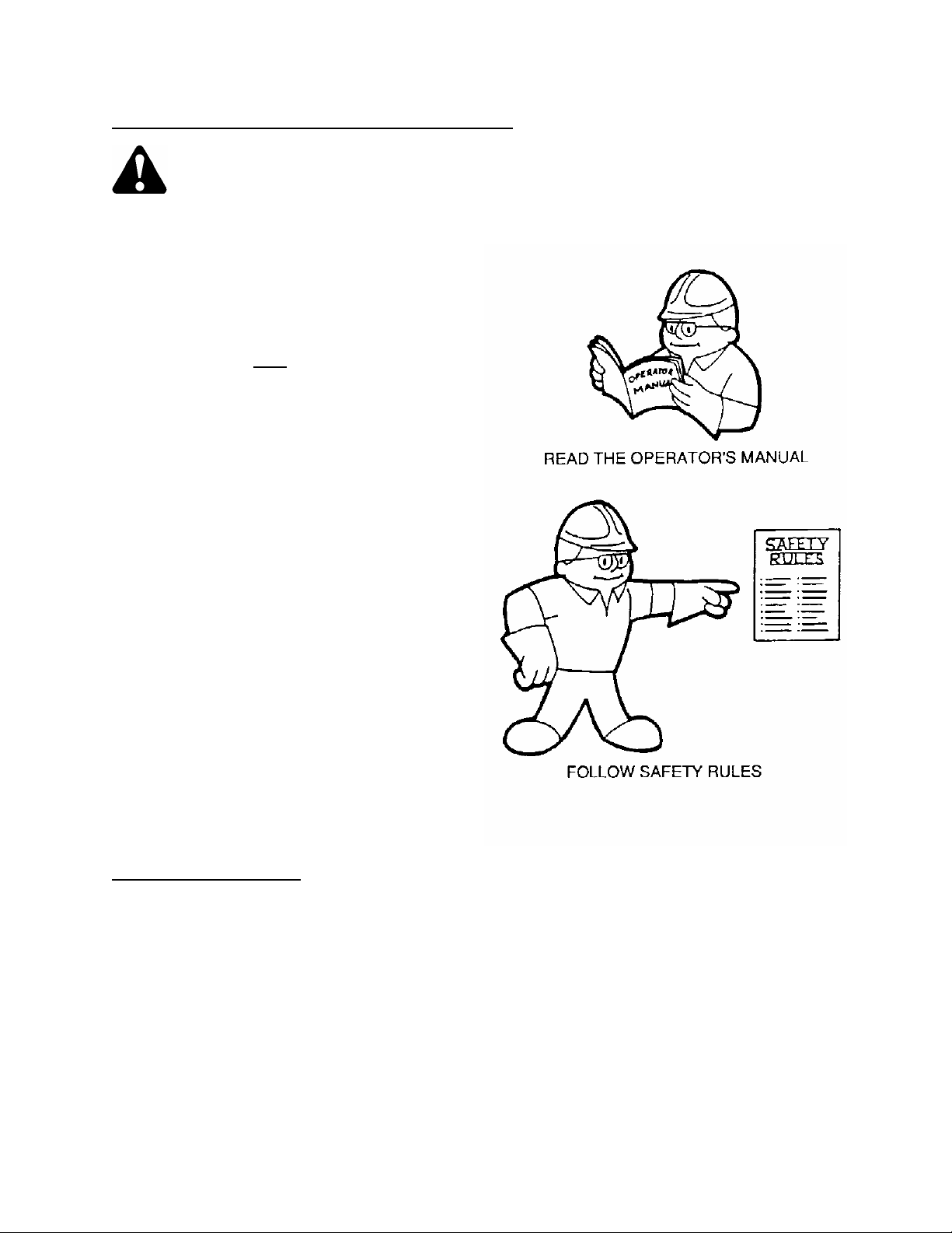
1. It is your responsibility to read and
understand this manual completely before
operating the windrower. Contact your
dealer if an instruction is not clear to you.
2. Follow all safety messages in the manual
and on safety signs on the machine.
3. Remember that YOU
Good safety practices protect you and the
people around you.
4. Before allowing anyone to operate the wind-
rower, for however short a time or distance,
make sure they have been instructed in its
safe and proper use.
5. Review the manual and all safety related
items with all operators annually.
6. Be alert for other operators not using
recommended procedures or not following
safety precautions. Correct these mistakes
immediately , before an accident occurs.
7. Do not modify the machine. Unauthorized
modifications may impair the function
and/or safety and affect machine life.
8. The safety information given in this manual
does not replace safety codes, insurance
needs, or laws governing your area. Be sure
your machine meets the standards set by
these regulations.
TO THE NEW OPERATOR
It's natural for an operator to be anxious to get
started with a new machine. Please take the time
to familiarize yourself with the windrower by
reading the Operator's Manual and safety signs
before attempting operation.
are the key to safety.
4
Page 16

OPERATION
PREPARING THE TRACTOR
1. Select proper tractor size:
For 21', 25' or 30' units
required is 40 hp (30 kw) and minimum tractor
weight is 5000 lbs. (2270 kg).
For 36' unit
hp (38 kw) and minimum tractor weight is 6000
lbs. (2720 kg).
For all sizes, minimum hydraulics required are
1800 psi (12400 kPa) pressure with dual
remote capability.
2. For tractors with variable PTO speed, select
540 or 1000 rpm to match windrower speed
option. See "Preparing the Windrower" in this
section.
3. Adjust tractor drawbar to meet ASAE Standard
specifications as listed below for the PTO
speed to be used (540 or 1000 rpm). An
improperly located drawbar may damage the
universal joints of the implement driveline,
and/or affect machine performance
Be sure the following specifications are met:
(A) 14 in. (356 mm) for 540 rpm.
16 in. (406 mm) for 1000 rpm.
(B) 6 to 12 in. (152 to 305 mm)
(C) 13 to 17 in. (330 to 432 mm)
NOTE: An offset drawbar (D) can be turned
over if required to meet specifications (B) and
(C).
4. Secure the drawbar so the hitch pin hole is
directly below the driveline.
NOTE: If the tractor has a three point hitch,
raise the lower links as high as possible, to
prevent damage.
5. Attach support (E) for hitch chain to suitable
location on tractor drawbar, maximum 6 inches
(150 mm) from hitch pin hole. For 36 ft. unit,
also note item 7.
, the minimum power required is 50
, the minimum power
STANDARD DRAWBAR SPECIFICATIONS
OFFSET TRACTOR DRAWBAR
ATTACH SUPPORT FOR HITCH CHAIN
5
Page 17
OPERATION
PREPARING THE TRACTOR
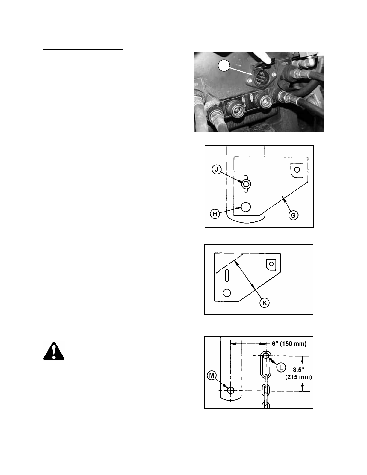
6. Tractor must be equipped with a seven terminal
outlet (F) to supply power to the windrower's
warning and work lights.
7. For 36' units only
(G) to the tractor drawbar as follows:
- Position plate on drawbar so hitch pin hole
lines up with 1-1/4 inch (32 mm) hole in plate at
(H).
- The slotted hole in plate should line up with a
second hole in the drawbar at (J). Install 5/8
Grade 5 bolt, washer and locknut at (J).
NOTE: If slotted hole does not line up with a
drawbar hole drill a hole in plate (G) to match
drawbar.
- Some tractor drawbars may require the plate
be trimmed to fit. If so. do not leave less than 5
inches (125 mm) width (K) or plate may yield
under extreme conditions.
- If, for any reason, the chain anchor plate
cannot be fitted to the tractor drawbar,
provision must be made for fastening chain to
the tractor frame at the correct location (L). Use
the anchor plate as a guide or locate the
position by measuring carefully from the hitch
pin hole (M).
CAUTION: To avoid injury and/or
machine damage, do not shorten the
stabilizer chain or attach it further
away than the specified 6 in. (150 mm) to the
right of the hitch pin hole center line.
: Attach chain anchor plate
(continued)
SEVEN TERMINAL ELECTRICAL OUTLET
F
INSTALL CHAIN ANCHOR PLATE - 36'
5" (125 mm) MINIMUM WIDTH
IF TRIMMING REQUIRED
CHAIN PIN HOLE LOCATION
IF PLATE CANNOT BE USED
6
Page 18
OPERATION
PREPARING THE WINDROWER
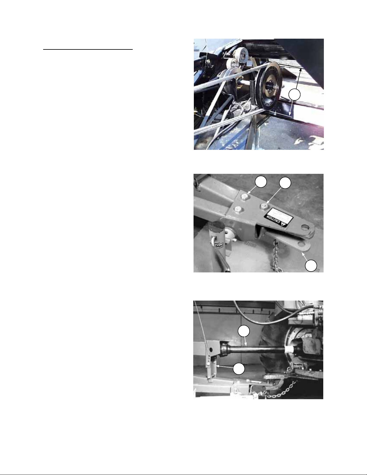
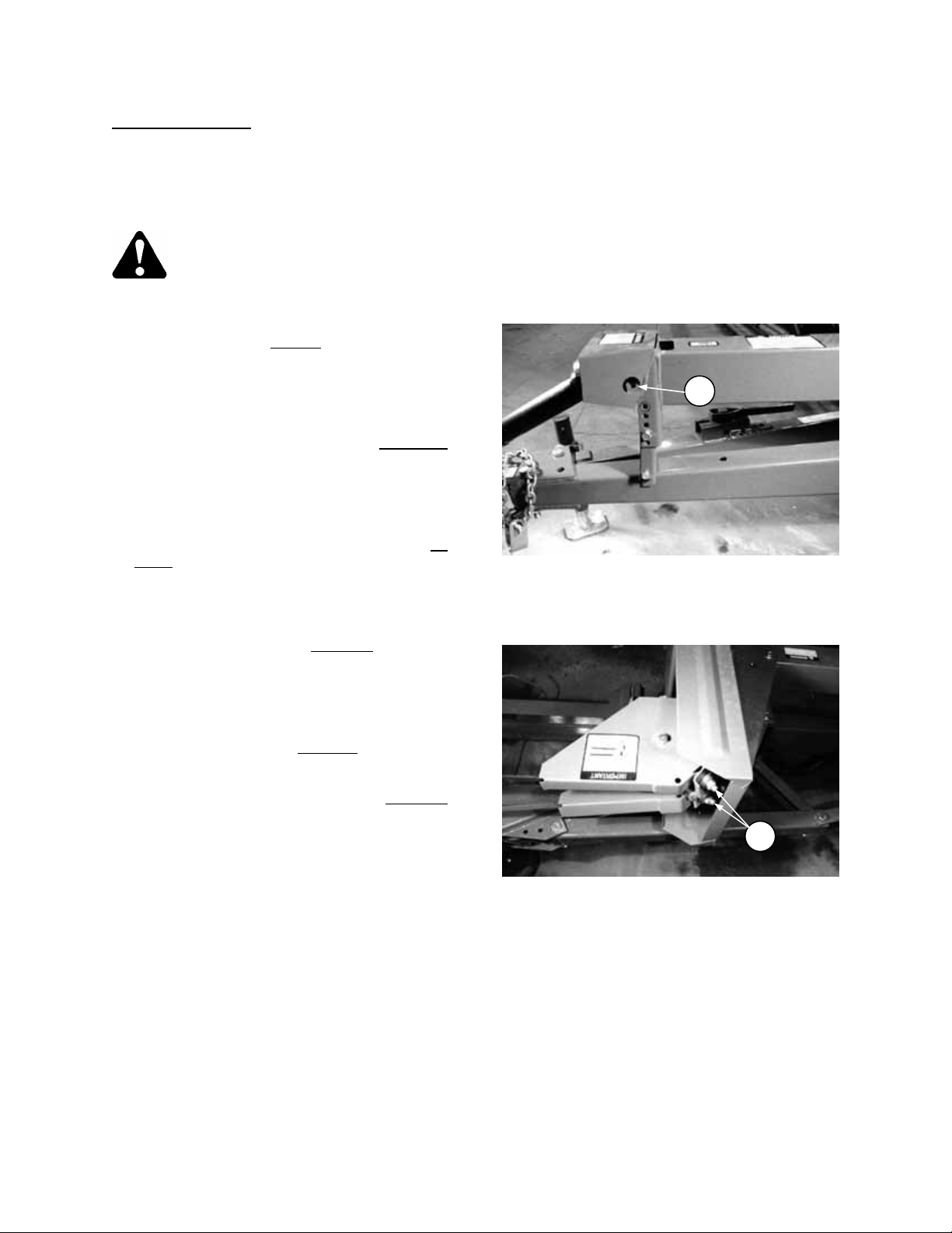
1. Be sure windrower is set up to match tractor
PTO speed. A quick way to check is to
measure the outside diameter of the driven
pulley (A):
9-1/2 inch (240 mm) - 540 rpm
12-1/2 inch (320 mm) - 1000 rpm
If not matched, and tractor PTO speed cannot
be varied, order a conversion kit from your
windrower dealer. (Kit includes front yoke,
decal and instructions.)
IMPORTANT: To avoid machine damage, follow
instructions provided in kit for removal of main
drive pulley. This procedure is also detailed under
"Removal of Main Drive Pulley" in Maintenance/
Service section.
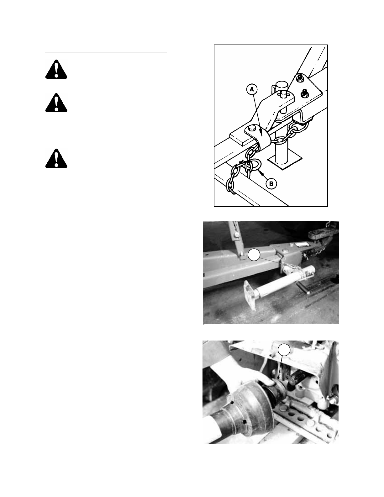
2. Use correct hitch type: For tractors with clevis
type drawbar, windrower hitch is compatible
without modification. For tractors with straight
drawbar, an optional hitch plate (B) is available
to convert windrower hitch to clevis type.
To install:
- Remove bolt (C) securing hitch chain.
- Position plate (B) under hitch and replace bolt
(C) to secure hitch chain.
- Install bolt (D) from option kit and secure with
locknut.
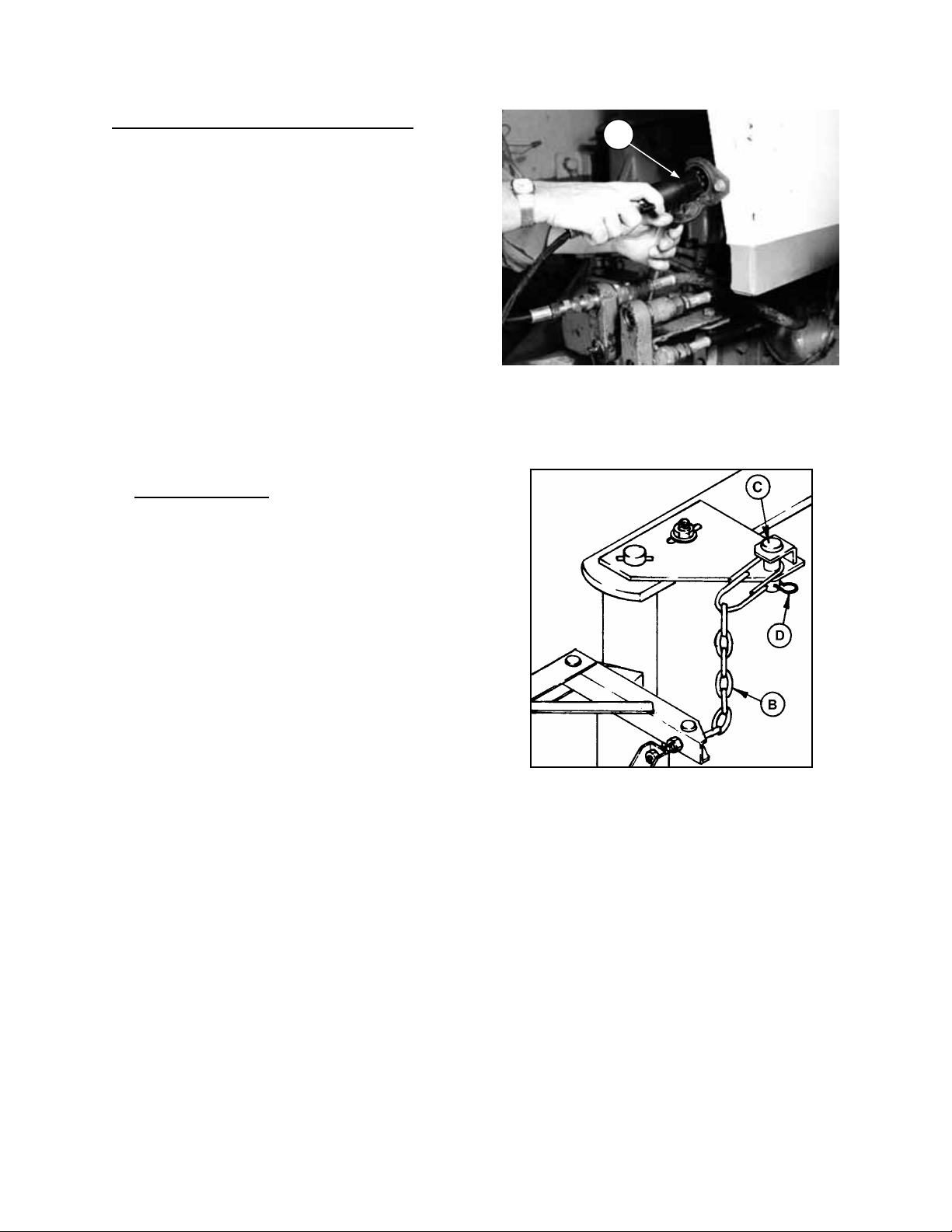
3. With tractor drawbar adjusted to recommendations listed under "Preparing the Tractor",
adjust the drive frame vertically at (E) so
telescoping driveline (F) is in straight line with
tractor PTO.
NOTE: The telescoping driveline (F) should
slide under hand pressure. Grease if required.
4. Install quick coupler tips matching the tractor to
be used on the two hydraulic hoses going to
the tractor.
TRACTORS WITH STRAIGHT DRAWBAR
A
MEASURE PULLEY TO DETERMINE
PTO SPEED OPTION
D
OPTIONAL HITCH PLATE FOR
F
E
C
B
DRIVELINE IN STRAIGHT LINE WITH PTO
7
Page 19

OPERATION
PREPARING THE WINDROWER
5. Check the tires and inflate if necessary.
Recommended pressure is 24 to 28 psi (165 to
190 kPa).
CAUTION: When inflating tires, use a
clip-on chuck and extension hose
long enough to allow you to stand to
one side and not facing the tire.
6. Check the tension of all belts and adjust if
required. See Maintenance/Service section.
7. IMPORTANT: Check that main drive belt is
properly aligned. Misalignment will result in belt
failure. See "Main Drive Belt Alignment" in
Maintenance/Service section.
8. Lubricate the machine completely. See
Maintenance/Service section.
9. Check for proper assembly and adjustment and
make sure all bolts are tightened securely.
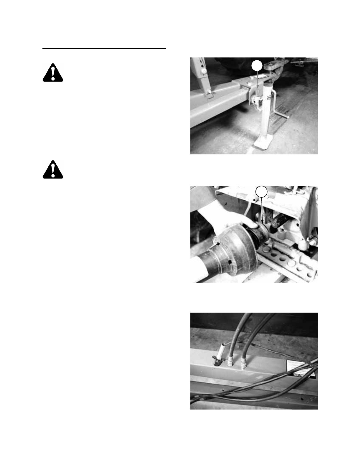
10. For 36 ft. units only
(G) as follows:
- Position machine as when moving straight
ahead in field position. Stabilizer chain (H) will
be taut.
- Adjust stop bolt (G) to just contact stabilizer
channel (J).
: Adjust stabilizer stop bolt
(continued)
STAND TO ONE SIDE WHEN INFLATING TIRES
ADJUST STABILIZER STOP BOLT - 36'
8
Page 20
OPERATION
ATTACHING WINDROWER TO TRACTOR
CAUTION: Shut off tractor, engage
parking brake and remove key before
working around hitch.
CAUTION: Never attach windrower to
tractor rear axle or three-point hitch
arms.
1. Attach windrower hitch to tractor drawbar with a
1-3/16 inch (30 mm) pin and secure with a
spring locking pin or other suitable fastener.
CAUTION: To prevent damage to
driveline guards, use a drawbar hitch
pin with a low head.
NOTE: For 36 ft. units it is especially important
to use the largest diameter hitch pin possible,
to limit possible rotation of the stabilizer chain
anchor plate.
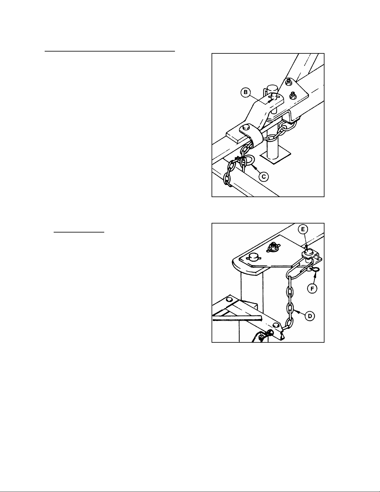
2. Route hitch chain from windrower through
chain support (A), around drawbar support and
lock hook (B) on chain.
IMPORTANT: Adjust chain length to remove all
slack except what is needed for turns.
3. Remove weight from jack. Remove pin (C) and
rotate jack to storage position. Replace pin,
looping the retaining chain around jack handle
to prevent dragging.
4. Pull back spring loaded collar (D) on
telescoping driveline yoke and slide collar onto
tractor PTO shaft. Release collar, ensuring
yoke locks in position on shaft.
INSTALL HITCH PIN AND CHAIN
C
JACK STORAGE
D
ATTACH DRIVELINE TO PTO
9
Page 21
OPERATION
ATTACHING WINDROWER TO TRACTOR
(continued)
5. Connect the windrower wiring harness plug (A)
to outlet on tractor.
6. Connect hydraulic hoses to tractor remote
cylinder control valves.
7. For 36 ft. units only
tractor-mounted anchor plate as follows:
- Windrower must be in transport position; or, if
in field position, tractor must be situated as in a
right turn.
- Attach chain (B) to anchor plate, securing with
pin (C) and hair pin (D).
: Attach stabilizer chain to
A
CONNECT WIRING HARNESS
ATTACH STABILIZER CHAIN - 36 ft.
10
Page 22
OPERATION
DETACHING WINDROWER FROM TRACTOR
CAUTION: To prevent accidental
movement of tractor, shut off engine,
engage parking brake, and remove
key.
To maintain stability, always lower the reel and
cutterbar completely. Block windrower wheels
before detaching from tractor.
Park machine on flat level surface.
Move remote cylinder control valve lever back
and forth to relieve stored hydraulic pressure.
CAUTION: For 36 ft. units, windrower
must be in transport position; or, if in
field position, tractor must be
situated as in a right turn to relax
stabilizer spring and slacken chain.
1. Remove pin (A) and rotate jack to upright
position. Replace pin, allowing jack handle to
swing freely.
2. Lower jack to take weight off tractor drawbar.
3. Pull back spring loaded collar (G) on
telescoping driveline yoke and remove yoke
from tractor PTO shaft.
4. Disconnect hydraulic hoses and electrical
harness. Store in holes provided in drive frame.
A
LOWER JACK
G
DETACH DRIVELINE
STORE HOSES AND WIRING HARNESS
11
Page 23
OPERATION
DETACHING WINDROWER FROM TRACTOR
(continued)
5. Remove hitch pin (B) and unhook chain (C)
from tractor. Wrap chain around windrower
hitch for storage.
6. For 36 ft. units only
(D) from tractor, storing pins (E) and (F) in
position.
7. Slowly drive tractor away from windrower.
: Disconnect stabilizer chain
REMOVE HITCH PIN AND CHAIN
DISCONNECT STABILIZER CHAIN - 36 ft.
12
Page 24
OPERATION
BREAK-IN PERIOD
1. After attaching windrower to tractor for the first
time, operate the machine slowly for 5 minutes,
watching and listening FROM THE TRACTOR
SEAT for binding or interfering parts.
CAUTION: Before investigating an
unusual sound or attempting to
correct a problem, shut off tractor,
engage parking brake and remove
key.
2. Check all belts after 5 hours
stretch. Tighten as necessary. (See
Maintenance/Service section). Continue to
check the belts periodically for the first 50
hours.
3. Check wheel bolt torque after 10 hours
operation and periodically thereafter (at least
every 100 hours). Torque to 80 to 90 ft.lbs.
(110 to 120 N⋅m)
4. Check that the two setscrews securing driveline
yoke to main drive shaft at (A) are tight after 10
hours operation.
5. Check locknuts (B) after 10 hours
Torque to 80 to 90 ft.lbs. (110 to 120 N⋅m).
Also check that top idler pulley is properly
aligned with drive pulley. See "Main Drive Belt
Alignment" in Maintenance/Service section
6. Check sickle drive after 10 hours
loose bearings and/or bolts.
7. Check reel and draper drives after 10 hours
operation for proper alignment and heated
bearings.
8. Until you become familiar with the sound and
feel of your new windrower, be extra alert and
attentive.
operation for initial
CHECK YOKE - DRIVE SHAFT SETSCREWS
operation.
operation for
A
B
CHECK IDLER BRACKET LOCKNUTS
AND BELT ALIGNMENT
13
Page 25

OPERATION
PRE-STARTING CHECKS
Do the following at the start of each operating
season:
CAUTION:
1. Review the Operator's Manual to refresh
your memory on safety and operating
recommendations.
2. Review all safety signs and other decals on
the windrower and note hazard areas.
3. Be sure all shields and guards are properly
installed and secured. Never alter or remove
safety equipment.
4. Be sure you understand and have practised
safe use of all controls. Know the capacity
and operating characteristics of the
machine.
5. Check the first aid kit and fire extinguisher.
Know where they are and how to use them.
Also:
6. Install drapers. See "Drapers" in Maintenance/
Service section.
7. Adjust tension on drive belts and drapers. See
Maintenance/Service section.
8. Perform all Annual maintenance. See Maintenance/Service section.
14
Page 26
OPERATION
PRE-STARTING CHECKS
Do the following each day before start-up:
CAUTION:
1. Clear the area of other persons, pets etc.
Keep children away from machinery. Walk
around the windrower to be sure no one is
under, on or close to it.
2. Remove foreign objects from the machine
and surrounding area.
3. Wear close fitting clothing and protective
shoes with slip resistant soles.
As well, carry with you any protective
clothing and personal safety devices that
COULD be necessary through the day. Don't
take chances.
You may need:
- a hard hat
- protective glasses or goggles
- heavy gloves
- respirator or filter mask
- wet weather gear.
4. Protect against noise. Wear a suitable
hearing protective device such as ear muffs
or ear plugs to protect against
objectionable or uncomfortable loud noises.
5. Check the machine for leaks or any parts
that are missing, broken, or not working
correctly.
NOTE: Use proper procedure when
searching for pressurized fluid leaks. See
"Hydraulics" in Maintenance/Service
section.
6. Be sure tractor and windrower are properly
attached, all controls are in neutral and
tractor brake is engaged.
7. Clean all lights and reflective surfaces on
the machine. Check lights for proper
operation.
8. Apply draper tension by rotating tension levers
(A) towards center of drapers.
9. Perform all Daily maintenance. See Maintenance/Service section.
PROTECT YOURSELF
PROTECT AGAINST NOISE
A
APPLY DRAPER TENSION
15
Page 27

OPERATION
OPERATE CORRECTLY
CAUTION:
1. Follow all safety and operational instructions given in your tractor Operator's Manual. If you do not
have a tractor manual, get one from your dealer and read it thoroughly.
2. Never attempt to start the tractor engine or operate the windrower except from the tractor seat.
3. Check the operation of all controls in a safe clear area before starting work.
4. Do not allow riders on tractor or windrower.
5. Never start or move the machine until you are sure all bystanders have cleared the area.
6. Avoid travelling over loose fill, rocks, ditches or holes.
7. Drive slowly through gates and doorways.
8. Reduce speed when turning, crossing slopes, or when travelling over rough ground.
9. When working on inclines, travel uphill or downhill when possible. Be sure to keep tractor
transmission in gear when travelling downhill.
10. Never attempt to get on or off a moving tractor.
11. Do not get off the tractor while the windrower is in operation.
12. Stop tractor engine and remove key before adjusting or removing plugged material from the
machine. A child or even a pet could engage the drive.
13. Check for excessive vibration and unusual noises. If there is any indication of trouble, shut down
and inspect the machine. Follow proper shut-down procedure:
- engage tractor brake
- disengage PTO
- turn off engine and remove key
- wait for all movement to stop
- dismount and engage cylinder stops before inspecting raised machine.
16
Page 28

OPERATION
IMPORTANT: Satisfactory function of the
windrower in all situations requires making proper
adjustments to suit various crops and conditions.
Correct operation reduces crop loss and allows
cutting of more acres. As well, proper adjustments
and timely maintenance will increase the length of
service you receive from the machine.
ENGAGING THE PTO
DANGER: Be sure all bystanders are
clear of the machine before engaging
the PTO. Never leave tractor seat
with the PTO engaged. Entanglement with
rotating driveline will cause serious injury or
death.
• Engage the PTO slowly, just before the
windrower is moved up to the standing crop.
Engage PTO only when tractor is angled less
than 45° to driveline.
• Be sure tractor PTO speed and windrower drive
are matched. See "Preparing the Windrower" in
this section.
• Disengage the PTO when not operating the
windrower.
CUTTING WIDTH
Unless combine capacity is a limiting factor, run
the left side of the header close to the edge of the
standing crop, taking a full cut. If a full width
windrow will overload your combine, cut less than
a full windrower width. Overloading the combine
means wasted crop, high fuel consumption, and
possible repair bills.
RIGHT HAND DIVIDER ROD
The divider rod (A) can be angled in or out to
provide proper separation and clean entry in a
variety of crops. To change angle; loosen
hardware, move rod to desired position and tighten
hardware.
CLEAR THE AREA BEFORE ENGAGING PTO
A
RIGHT DIVIDER ROD ADJUSTMENT
17
Page 29

OPERATION
HEADER LOCK
WARNING: To avoid bodily injury or
death from fall of raised machine,
always engage header lock (A)
before going under windrower for any reason.
NOTE: Should the condition arise where the lock
pin cannot be installed with the header fully raised,
install shim washers between bracket (B) and stop
(C).
When not in use, store pin at (D).
CUTTING HEIGHT
IMPORTANT: Avoid raising header to full height
when in field position. Right wheel may rotate into
transport position.
The windrow should normally be laid on stubble
from 6 to 8 inches high (150 to 200 mm).
Benefits of a stubble of this height:
• Allows free circulation of air under the windrow
for more even drying.
• Supports the windrow without bending.
• Keeps grain heads from contacting ground.
Heads that touch the ground are difficult to pick
up and will sprout in damp weather.
Cutting height is controlled from the tractor with
remote cylinder control valve lever.
Minimum Header Height
The header lift cylinder has an adjustable stop to
vary minimum header height. To adjust:
1.
WARNING: To avoid bodily injury or
death, raise header fully and engage
header lock.
2. Turn stop (E) towards cylinder barrel to raise
minimum height.
MINIMUM HEADER HEIGHT ADJUSTMENT
D
A
C
B
HEADER LOCK - ENGAGED
E
18
Page 30

OPERATION
GROUND SPEED
CAUTION: Reduce speed when turning, crossing slopes, or when travelling over rough
ground.
Tractor ground speed should not exceed 8 mph (13 km/h). For most crop conditions a ground speed of 5 mph
(8 km/h) has been found satisfactory.
Choose a ground speed that allows the sickle to cut the crop smoothly and evenly, while giving the desired
windrow formation.
NOTE: Ground speed affects the orientation of stalks in the windrow. Increasing ground speed will cause the
configuration of the windrow to go from parallel formation to herringbone or dovetail. See "Windrow
Characteristics" in this section.
As ground speed is increased, draper and reel speed should be increased to handle the extra material.
The chart below indicates the relationship between ground speed and area cut for each windrower size.
Example (see arrows below): At ground speed of 5 mph (8 km/h), a 36 ft. windrower will cut approximately 22
acres (9 hectares) per hour.
19
Page 31

OPERATION
REEL SPEED
Reel speed affects the smoothness and evenness
of the windrow. Operating the reel too fast or too
slow relative to ground speed will cause bunching
in the windrow.
In standing crop, reel speed should be just faster
than ground speed to sweep the crop across the
sickle.
A faster reel speed may be necessary in leaning or
down crop.
Excessive shattering of grain heads may be an
indication that reel speed is too fast.
Reel speed is variable from 27 to 50 rpm, over two
speed ranges.
To adjust speed within a range
1. To reduce speed, move shims at (A) from
outside to between pulley halves.
2. To increase speed, remove shims from
between halves and store outside pulley.
To change speed range
(B) as follows:
1. Remove nut (C), shims at (A) and outer pulley
half (B).
2. Remove pulley half (D) under main drive shield
and store the pulley half removed in Step 1.
3. Install new pulley half on drive shaft, position
shims as required, and secure with nut.
NOTE: The smaller diameter pulley half is used for
the low speed range. The larger diameter pulley
half is used for the high speed range.
:
, replace outer pulley half
A
B
REEL SPEED ADJUSTMENT
D
C
STORAGE OF PULLEY HALF
20
Page 32

OPERATION
REEL PROPS
Keep pivot bolt properly tightened so prop remains
in stored position when not in use, yet can be
engaged with hand force.
36 foot units only
To engage center reel arm lock pin, raise reel and
install pin at (B). Secure with hair pin.
When not in use, store pin at (C).
REEL HEIGHT
Reel height is controlled from the tractor with
remote cylinder control valve lever. Depending on
crop height, adjust reel height to carry the material
through the sickle onto the drapers.
Down crop will require a lower reel height while
bushy crop may require raising the reel to prevent
unevenness in the windrow.
WARNING: To avoid injury from fall
of raised reel, always engage reel
props (A) before going under raised
reel for any reason.
:
A
REEL PROP - ENGAGED
B
C
CENTER SUPPORT ARM LOCK PIN
36 ft. UNIT - ENGAGED
21
Page 33

OPERATION
REEL POSITION - FORE & AFT
Reel fore-aft position can be adjusted to suit
various crop conditions:
For straight standing crop, the reel position is
normally centered above the cutterbar.
For crops that are down, tangled, or leaning, move
reel ahead of cutterbar.
Bushy crops require positioning the reel behind the
cutterbar, applying downward force on the crop
and drapers.
To adjust the fore-aft position of the reel
:
1. Position reel height so support arms (A) are
horizontal.
2. Loosen locknut (B) at left support arm.
3. Loosen jam nut and positioning screw (C)
under each support arm.
4. Slide the reel to desired position. A pry bar may
be used in hole (G).
REEL FORE-AFT POSITION ADJUSTMENT
NOTE: Positioning screw (C) must be in the same
hole on each support arm (A).
5. Tighten positioning screw (C), then tighten jam
nut at each support arm.
6. Tighten locknut (B) at left support arm.
7. Check that reel drive idler arm (D) is properly
positioned:
Idler position (E) - Reel in any of the three
forward positions.
Idler position (F) - Reel in any of the three
rearward positions.
A
G
B
D
C
E
F
REEL DRIVE IDLER ARM POSITION
22
Page 34

OPERATION
DRAPER SPEED
Draper speed affects the orientation of stalks in the
windrow. Faster draper speeds will tend to form
herringbone or dovetail configurations. See
"Windrow Characteristics" in this section.
Draper speed is variable from 275 to 480 feet per
minute (84 to 146 m/min) by shimming. One shim
will change draper speed approximately 19 feet
per minute (6 m/min)
To increase speed
pulley halves.
To decrease speed
pulley halves.
To change draper speed
1. Remove four bolts, shims (A) and outer pulley
half (B) at draper drive roller.
2. Reposition shims as required.
3. Replace pulley half, shims and bolts. Store
unused shims outside pulley.
4. Tighten hardware.
NOTE: When a slower draper speed is required
even after removing all shims at draper drive roller
pulley, add shims between pulley halves (C) on
drive shaft. However, for maximum belt life
extended use of shims at pulley (C) is not
recommended. When increasing speed, always
remove any shims at (C) first.
, add more shims between
, remove shims from between
:
,
A
B
DRAPER SPEED ADJUSTMENT
C
DRIVE SHAFT PULLEY
C
23
Page 35

OPERATION
DELIVERY OPENING WIDTH
The width of the delivery opening affects the width
and configuration of the windrow. The decision to
widen or narrow the opening should be based on
the following factors:
- Combine pick-up capability
- Weather conditions (rain, humidity, wind)
- Drying time available
See "Windrow Characteristics" in this section for
the strengths and weaknesses of the various
windrow configurations with respect to these
factors.
The 21, 25 and 30 ft. windrowers are factory
assembled with a delivery opening of 53 inches
(1345 mm).
To widen opening - 21, 25 & 30 ft. units
1. Remove screws from connector slat of right
hand draper.
2. Remove right hand draper drive belt. See
"Draper Drive Belts" in Maintenance/ Service
section.
3. Remove right draper track extension. Remove
roller support from extension. Store extension
on right leg of windrower.
4. Reinstall roller support (B) without extension.
5. Remove hardware securing drive roller at
cutterbar. Move roller (C) to bracket (D). Adjust
so roller (C) is perpendicular to cutterbar (E).
6. Re-connect draper at new length and cut off
excessive flap.
7. Install shorter drive belt provided.
8. Adjust draper tracking. See Maintenance/
Service section.
To narrow opening - 21, 25 & 30 ft. units
1. Obtain "Narrow Opening Option Package" from
your dealer.
2. Remove screws from connector slat of left
draper.
3. Add the 15 inch (380 mm) long extension (from
option package) to the draper.
4. Remove left hand draper drive belt. See
"Draper Drive Belts" in Maintenance/Service
section. Install longer belt (from option
package) on drive shaft pulley.
5. Remove left roller support. Attach extensions
(A) from option package and reinstall roller
support (B).
6. Remove hardware securing drive roller at
cutterbar. Move roller (C) to bracket (D). Adjust
so roller (C) is perpendicular to cutterbar (E).
7. Reconnect draper and install longer belt on
drive roller pulley.
8. Adjust draper tracking. See Maintenance/
Service section.
REMOVE RIGHT EXTENSION, REINSTALL
:
REPOSITION ROLLER AT CUTTERBAR
B
:
INSTALL DRAPER TRACK EXTENSIONS
B
ROLLER SUPPORT, CHANGE BELT
E
C
D
A
E
C D
24
REPOSITION ROLLER AT CUTTERBAR
Page 36

OPERATION
DELIVERY OPENING WIDTH
The 36 ft. windrower is factory assembled with a
delivery opening of 60-3/4 inches (1545 mm).
To widen opening - 36 ft. unit
1. Remove screws from connector slat of left
draper.
2. Remove two bolts (B) near left leg of
windrower.
3. Remove bolt (C) at cutterbar.
4. Push telescoping draper track to desired
position.
5. Install bolts (B) and (C).
6. Re-connect draper at new length and cut off
excessive flap.
7. Adjust draper tracking if necessary. See
Maintenance/Service section.
To narrow opening - 36 ft. unit
1. Remove screws from connector slat of left
draper.
2. Add a 15 inch (380 mm) long extension
(available as a repair part) to the draper.
Working from the factory set position, this
results in an opening width of 52-3/4 in. (1340
mm).
3. Remove two bolts (B) near left leg of
windrower.
4. Remove bolt (C) at cutterbar.
5. Pull telescoping draper track out to desired
position.
6. Install bolts (B) and (C).
7. Re-connect draper.
8. Adjust draper tracking if necessary. See
Maintenance/Service section.
(continued)
B
REMOVE BOLTS AT REAR TRACK
C
REMOVE BOLT AT CUTTERBAR
WARNING: Header raised for
photographic purposes. If adjusting
delivery opening with header raised,
first engage header lock.
25
Page 37

OPERATION
DELIVERY OPENING HEIGHT
Height of the frame tube can be adjusted within a
6” (150 mm) range by repositioning the caster
wheel spindle on the supports. A lower frame tube
height gives a flatter draper/guard angle, while
higher frame tube heights are beneficial in bulky
crops.
Adjust delivery opening height as follows:
1. Place jack at left or right end as shown.
BLOCK HEIGHTS:
L/H side – A 6” (150 mm) block (four 2x4’s) is
required under jack to raise to highest setting.
NOTE: When going from highest to lowest
position, a 6” block under jack is too high to
reach lowest position. Move in stages as
follows:
• Use a 6” block to move from high to
mid position.
• Lower onto wheel and remove one 2x4
to leave a 4-1/2” block.
• Jack up again and move from mid to
low setting.
R/H side – A 4-1/2” (115 mm) block (three
2x4’s) is adequate for all adjustments.
2. Remove four bolts and reposition spindle on
caster as desired. NOTE: Spindle hangs on
caster on a welded stud, so weight of wheel
does not need to be supported as adjustment is
made. Tighten bolts to 80 ft.lbs. (110 N⋅m).
NOTE: Factory assembly of casters is in a lower
clearance position, with rounded end of bracket up
as at (A). For highest settings, turn spindle bracket
180°, so rounded end is down as at (B).
3. Repeat at other end. See Levelling the
Cutterbar, below.
Levelling the Cutterbar
In field position, the right end of the cutterbar
should be 1 to 3 inches (25 to 75 mm) higher than
the left end to accommodate the weight of the
grain on the drapers when windrowing.
L/H SPINDLE BRACKET – FACTORY SETTING
LEFT WHEEL JACK POSITION – WHEEL
A
B
SHOWN IN RAISED POSITION
RIGHT WHEEL JACK POSITION
26
Page 38

OPERATION
WINDROW CHARACTERISTICS
Factors such as ground speed, reel speed, draper speed and delivery opening will all affect the resulting
windrow. You will quickly become adept at adjusting these variables to achieve the desired results.
NOTE: Crop condition is a major factor in forming a good windrow. While standing or uniformly leaning crops
can generally be easily formed into an acceptable windrow, such is not the case when stalks are tangled or
leaning in several directions.
There are three basic criteria by which the quality of a windrow is measured:
1. Weight Distribution - heads and stalks distributed evenly across full width of windrow.
2. Good Curing - a loose, open windrow for better drying.
3. Good Weatherability - a well formed windrow that supports heads off the ground and holds together in
extreme weather conditions.
HERRINGBONE WINDROW
The most desirable form of windrow, stalks are
crossed and interwoven. Heads are distributed
across full width of windrow. Windrow rating:
Weight Distribution: Good
Curing Characteristics: Good
Weatherability: Excellent
FANTAIL WINDROW
The stalk tips are crossed in the center and heads
are in line along outside edges. Windrow rating:
Weight Distribution: Fair
Curing Characteristics: Fair
Weatherability: Fair
DOVETAIL WINDROW
The stalk tips are lined along outside edges of
windrow and heads are crossed in center.
Windrow rating:
Weight Distribution: Poor
Curing Characteristics: Fair
Weatherability: Poor
PARALLEL WINDROW
The stalks are parallel to windrow and heads
evenly distributed across width of windrow.
Windrow rating:
Weight Distribution: Good
Curing Characteristics: Good
Weatherability: Good
HERRINGBONE WINDROW
FANTAIL WINDROW
DOVETAIL WINDROW
27
PARALLEL WINDROW
Page 39

OPERATION
CORNERING
Because of the long turning radius of the larger windrowers (especially 36 ft.), use the cornering procedure
illustrated.
This procedure will prevent swath disturbance and grain loss caused by tractor and/or windrower tires. In
addition, the technique should result in a corner that can be picked up by your combine without extra turning.
FIELD LIGHT
The field light (A) is positioned to shine on the
windrow when cutting after dark.
CAUTION: Do not turn work light on
when transporting the windrower on
roadways. Other drivers may be
confused by its position.
A
FIELD LIGHT
28
Page 40

OPERATION
UNPLUGGING THE SICKLE
WARNING: Stop tractor engine and
remove key before removing plugged
material from sickle. A child or even
a pet could engage the drive.
If the sickle plugs
1. Stop forward movement of the tractor.
2. Lift the cutterbar about 12 inches (300 mm).
3. Back up about 3 feet (1 metre) with PTO
engaged.
4. If the plug does not clear; disengage PTO, shut
off engine, remove key and lock tractor brakes.
5. Using bar through hole (A), manually work
sickle back and forth to loosen plugged
material.
WARNING: Wear heavy gloves when
working around sickle.
6. Clean off cutterbar by hand.
SHUT-DOWN PROCEDURE
CAUTION: Before leaving the tractor
seat for any reason:
1. Park on level ground if possible.
2. Lower the header and reel fully.
3. Place all controls in NEUTRAL or PARK.
4. Disengage PTO.
5. Engage the park brake.
6. Stop engine and remove key from ignition.
7. Wait for all movement to stop.
8. Lock tractor anti-vandalism covers and
closures when leaving the machine
unattended.
9. Release draper tension at the end of the day's
operation by using hand or foot to move lever
(B) over-center.
CAUTION: Spring loaded over-center
action causes handle to kick back
when tension is released. To avoid
possible injury, do not hold lever when
releasing tension.
:
A
CLEARING PLUGGED SICKLE
B
RELEASE DRAPER TENSION
29
Page 41

OPERATION
TRANSPORTING THE WINDROWER
CAUTION: Use correct transport
procedure as detailed here:
1. Be sure all lock pins are properly installed in
transport position. See "Converting From Field
Position to Transport" in this section.
2. To ensure adequate braking performance and
control, tow only with a vehicle weighing at
least 5000 lbs. (2300 kg).
3. Be sure hitch chain is properly attached to
towing vehicle. Provide only enough slack in
chain to permit turning. See "Attaching
Windrower to Tractor" in this section.
4. To avoid loss of control in turns, be sure there
is at least 4 inches (100 mm) clearance (A)
from hitch pin to rear of towing vehicle.
5. Disengage PTO before transporting. Be sure
driveline is properly attached to tractor PTO.
See "Attaching Windrower to Tractor" in this
section. If transporting with a truck, the front
driveline half must be removed and stored, or
otherwise adequately secured.
6. Check local laws for width regulations and
lighting or marking requirements before
transporting on roads.
7. Keep Slow Moving Vehicle emblem, reflectors
and lights clean and visible.
8. Do not allow riders on tractor or windrower.
9. Travel speed should be such that complete
control and machine stability are maintained at
all times. Do not exceed 20 mph (30 km/h).
Reduce speed for corners and slippery
conditions.
ENSURE CLEARANCE FOR TURNS
30
Page 42

OPERATION
TRANSPORTING THE WINDROWER
10. Transport Width
is as narrow as possible without compromising
machine stability. Recommended transport
widths (X) are:
21 ft. unit - 10'6" (3.2 m)
25 ft. unit - 10'10" (3.3 m)
30 ft. unit - 11'2" (3.4 m)
36 ft. unit - 12' (3.7 m)
Adjustment is made at right hand wheel, as
follows:
- To narrow transport width, loosen nut (A) and
turn nut (B) against bracket (C).
- To widen transport width, loosen nut (B) and
turn nut (A) against bracket (C).
- When optimum transport width is reached,
tighten nut to secure the position.
11. To maintain stability, transport with reel fully
lowered.
12. When transporting the windrower on a road or
highway, use the accessory lights to provide
adequate warning to operators of other
vehicles. The amber lights (A) are positioned to
mark the outline of the windrower, while the red
lights (B) mark the rear of the unit.
Do not use field light on roads or highways;
other drivers may be confused by its position.
13. Do not transport the windrower on a road or
highway at night, or in conditions which reduce
visibility, such as fog or rain.
14. Be aware of roadside obstructions, oncoming
traffic and bridges.
- Be sure transport width (X)
(continued)
ENSURE OPTIMUM TRANSPORT WIDTH
A
C
B
TRANSPORT WIDTH ADJUSTMENT
31
ACCESSORY LIGHT POSITIONS
Page 43

OPERATION
CONVERTING FROM FIELD POSITION TO
TRANSPORT
1. Raise header to full height.
2. Rotate levers from field to transport positions:
a. Rotate lever on hitch to transport position (A).
b. Rotate lever on left wheel lock to transport
position (B).
3. Drive forward, until telescoping hitch locks in
transport position. NOTE: A slight, temporary
increase in speed as well as steering to the left
will assist in starting the telescoping action of
the hitch. Slow down once hitch telescopes.
4. Once the hitch is locked, continue driving
forward slowly while holding header lift valve
control lever in the UP position until right wheel
rotates into transport position
NOTE: In hilly terrain, a slight variation in the
above procedure will provide more positive control
of the conversion process. This will require one
additional trip off the tractor. Proceed in the
following order: Step 1, Step 2a, Step 3, Step 2b,
Step 4, Step 5.
5. Install lock pins:
a. Install pin (C) in transport position on
telescoping hitch. Secure with hairpin.
b. Install pin (D) to lock header in raised position.
secure with hairpin.
NOTE: Should the condition arise where the lock
pin cannot be installed with the header fully raised,
see "Header Lock”, page 18.
HITCH LEVER - TRANSPORT POSITION
WHEEL LOCK LEVER - TRANSPORT POSITION
TELESCOPING HITCH PIN - TRANSPORT POSITION
A
B
C
D
32
HEADER LOCK - ENGAGED
Page 44

OPERATION
CONVERTING FROM FIELD POSITION TO
TRANSPORT
5. Install lock pins (continued)
c. Install pin (E) to lock right wheel in transport
position. Secure with hairpin.
CONVERTING FROM TRANSPORT TO FIELD
POSITION
1. Reverse windrower while steering tractor front
wheels to the left to angle caster wheel inward.
See diagram, Step 1.
2. Drive forward to check that the caster wheel
will turn inward, i.e. rotate under the backsheet.
If yes, continue forward until wheel is starting
face to the rear. See diagram, Step 2. If not,
repeat wheel positioning, Step 1.
3. Raise header to full height.
4. Place levers and pins in field position:
a. Remove lock pin (A) from telescoping hitch and
store. Secure with hairpin.
b. Rotate lever (B) on hitch to field position.
to
E
RIGHT WHEEL LOCK - ENGAGED
B
A
33
HITCH LEVER & PIN - FIELD POSITION
Page 45

OPERATION
CONVERTING FROM TRANSPORT TO FIELD
POSITION
4. Place levers and pins in field position
(continued):
c. Remove pin (C) at header lock and store.
Secure with hairpin.
d. Rotate lever on left hand wheel lock to field
position (D).
e. Remove pin at right wheel lock and store at (E).
Secure with hairpin.
5. Turn tractor front wheels to the right and back
up until left wheel locks in field position.
6. Turn tractor front wheels left and back up to
pivot the front hitch, shortening telescoping
member (B) until it locks in position.
NOTE: Turn tractor wheels as required to
prevent left rear tractor tire from contacting
hitch.
If left wheel (A) has not fully castered and
locked in field position, continue backing up
until procedure is completed.
7. Drive ahead slowly while lowering header halfway to ground, allowing right wheel (C) to
rotate to field position.
IMPORTANT: Avoid lowering header
completely before right wheel rotates to field
position. This causes high loads on the
cylinder, possibly resulting in early failure.
8. Engage PTO only when angle (D) is 45° or
less.
HEADER LOCK PIN - STORAGE POSITION
WHEEL LOCK LEVER - FIELD POSITION
C
D
E
RIGHT WHEEL LOCK PIN - STORAGE
34
FIELD POSITION
Page 46

OPERATION
STORAGE PROCEDURE
Do the following at the end of each operating
season:
CAUTION:
1. Clean the windrower thoroughly. Never use
gasoline, naphtha or any volatile material
for cleaning purposes. These materials may
be toxic and/or flammable.
2. Cover cutterbar and sickle guards to
prevent injury from accidental contact.
Also:
3. Store in a dry, protected place if possible. If
stored outside, always cover windrower with a
waterproof canvas or other protective material.
4. If machine is stored outside, remove drapers
and store in a dark, dry place.
NOTE: If drapers are not removed, release
tension and angle header so water/snow will
not accumulate on drapers. This accumulation
of weight puts excessive stress on drapers and
header.
5. Lower header onto blocks to keep cutterbar off
the ground.
6. Lower reel completely. If stored outside, tie reel
to frame to prevent rotation caused by wind.
7. Repaint all worn or chipped painted surfaces to
prevent rust.
8. Loosen all drive belts.
9. Lubricate the windrower thoroughly, leaving
excess grease on fittings to keep moisture out
of bearings. Apply grease to exposed threads,
cylinder rods and sliding surfaces of
components. Oil sickle components to prevent
rust.
10. Check for worn or broken components and
repair or order replacements from your dealer.
Attention to these items right away will save
time and effort at beginning of next season.
11. Replace or tighten any missing or loose
hardware. See Specifications section for torque
charts.
35
Page 47

MAINTENANCE/SERVICE
SERVICE PROCEDURES
CAUTION: To avoid personal injury,
before servicing windrower or
opening drive covers:
1. Fully lower the header and reel. If necessary
to service in the raised position, always
engage header lock and reel props.
2. Disengage PTO.
3. Stop engine and remove key.
4. Engage park brake.
5. Wait for all
Park on level surface when possible. Block
wheels securely if windrower is parked on an
incline. Follow all recommendations in your
Tractor Operator's Manual.
Wear close-fitting clothing and cover long hair.
Never wear dangling items such as scarves or
bracelets.
Wear protective shoes with slip-resistant soles,
a hard hat, protective glasses or goggles and
heavy gloves.
Be prepared if an accident should occur. Know
where the first aid kit and fire extinguishers are
located and how to use them.
Keep the service area clean and dry. Wet or
oily floors are slippery. Wet spots can be
dangerous when working with electrical
equipment. Be sure all electrical outlets and
tools are properly grounded.
Use adequate light for the job at hand.
Replace all shields removed or opened for
service.
Use only service and repair parts made or
approved by the equipment manufacturer.
Substituted parts may not meet strength,
design or safety requirements.
Keep the machine clean. Never use gasoline,
naphtha or any volatile material for cleaning
purposes. These materials may be toxic and/or
flammable.
BELTS
pulley. Loosen the necessary components to allow
easy installation, then adjust tension to the
minimum required to prevent slipping.
: When installing a new belt, never pry over
moving parts to stop.
36
Page 48

MAINTENANCE/SERVICE
GREASING THE WINDROWER
Use an SAE Multi-Purpose High Temperature
Grease with Extreme Pressure (EP) Performance
and containing at least 1.5% molybdenum
disulphide.
Also acceptable is an SAE Multi-Purpose Lithium
Base Grease.
The following greasing points are marked on the
machine by decals showing a grease gun (A), and
grease interval (B) in hours of operation. Log your
hours of operation and use the "Maintenance
Checklist" provided to keep a record of scheduled
maintenance.
Procedure:
1. Wipe grease fitting with a clean cloth before
greasing, to avoid injecting dirt and grit.
2. Inject grease through fitting with grease gun
until grease overflows fitting.
3. Leave excess grease on fitting to keep out dirt.
4. Replace any loose or broken fittings
immediately.
5. If fitting will not take grease, remove and clean
thoroughly. Also clean lubricant passageway.
Replace fitting if necessary.
10 Hours or Daily
DANGER: Stay clear of driveline until
all movement has stopped.
Entanglement with rotating driveline
will cause serious personal injury or
death. Avoid loose fitting or dangling
clothing.
1. Telescoping Driveline (C) - three fittings
:
STAY CLEAR OF ROTATING DRIVELINE
SAMPLE GREASE DECAL
C
TELESCOPING DRIVELINE
37
Page 49

MAINTENANCE/SERVICE
GREASING THE WINDROWER (continued)
50 Hours
1. Main Hitch Pivots (A) - four fittings
2. Wheel Casters (B) & (C) - two fittings
3. Reel Support Bushings (D)
:
21, 25, 30 ft. - two fittings
36 ft. - three fittings
A
B
LEFT WHEEL CASTER RIGHT WHEEL CASTER
MAIN HITCH PIVOTS
C
D
REEL SUPPORT BUSHINGS
38
Page 50

MAINTENANCE/SERVICE
GREASING THE WINDROWER
100 Hours or Annually
1. Drive Shaft Bearings (A) - two fittings
2. Drive Shaft Wooden Support Bearing (B)
36 ft. only - one fitting
3. Countershaft Bearings (C) - two fittings
:
(continued)
DRIVE SHAFT WOODEN SUPPORT BEARING
DRIVE SHAFT BEARINGS
A
B
36 ft. ONLY
C
COUNTERSHAFT BEARINGS
39
Page 51

MAINTENANCE/SERVICE
GREASING THE WINDROWER
100 Hours or Annually
(continued):
4. Sickle Drive Pulley Bearings (D) - one fitting
5. Pitman Bearings (E) - two fittings
6. Draper Drive Shaft Bearings (F)
21, 25, 36 ft. - three fittings
30 ft. - four fittings
7. Draper Drive Shaft Wooden Support Bearings
(G) - 36 ft. only - three fittings
Remove center shield for access.
SICKLE DRIVE PULLEY AND PITMAN BEARINGS
DRAPER DRIVE SHAFT BEARINGS
E
D
F
G
DRAPER DRIVE SHAFT WOODEN
SUPPORT BEARINGS - 36 ft. ONLY
40
Page 52

MAINTENANCE/SERVICE
GREASING THE WINDROWER
100 Hours or Annually
8. Draper Drive Roller Bearings (H) - two fittings
9. Reel Drive Pulley Hub (K) - one fitting
11. Wheel Hub Bearings (M) – two fittings
REEL DRIVE PULLEY HUB
(continued):
10. Split Reel Connector Block (L)
36’ – one fitting
K
H
DRAPER DRIVE ROLLER BEARINGS
SPLIT REEL CONNECTOR BLOCK
36’ ONLY (not exactly as shown)
L
M
WHEEL HUB BEARINGS
41
Page 53

MAINTENANCE/SERVICE
TELESCOPING HITCH PIN
Lubricate pin (A) every 100 hours or once per
season with a lightweight (SAE 30) oil.
LEFT WHEEL LOCK ASSEMBLY
Lubricate handle (B) and lock assembly every 100
hours or once per season with a lightweight (SAE
30) oil.
HEADER FLOTATION
Header flotation should be set so header can be
lifted with 100 to 150 lbs. force (450 to 650 N) at
right hand divider rod.
NOTE: Check float with cutterbar 6 to 8 inches
(150 to 200 mm) off ground.
To adjust:
1. Support cutterbar on 6 inch (150 mm) blocks.
2. Turn float adjusting screw (A) clockwise to
increase float (that is, less force will be required
to lift header as described). Turn float screw
counterclockwise to reduce float.
NOTE: Keep threads of float adjusting screw (A)
greased.
NOTE: For 21' and 25' headers with pick-up reel,
an extra leaf spring can be added.
To install extra spring:
OIL TELESCOPING HITCH PIN
OIL LEFT WHEEL LOCK ASSEMBLY
- Back off bolt (A).
- Block cutterbar with 6” (150 mm) blocks
each end.
- Remove spacer from float spring pocket
(both ends) to make room for the fourth
spring.
A
B
A
HEADER FLOTATION ADJUSTMENT
42
Page 54

MAINTENANCE/SERVICE
HYDRAULICS
Check hydraulic hoses and lines daily
leaks.
Relieve pressure before disconnecting
hydraulic lines. Tighten all connections before
applying pressure. Keep hands and body away
from pin- holes and nozzles which eject fluids
under high pressure. Use a piece of cardboard
or paper to search for leaks. If ANY fluid is
injected into the skin, it must be surgically
removed within a few hours by a doctor
familiar with this type of injury or gangrene
may result.
IMPORTANT: Keep hydraulic coupler tips and
connectors clean. See "Detaching Windrower from
Tractor" in Operation section for storage of hoses.
Dust, dirt, water and foreign material are the major
causes of hydraulic system damage.
for signs of
WARNING: Avoid high-pressure
fluids. Escaping fluid can penetrate
the skin causing serious injury.
AVOID HIGH-PRESSURE FLUIDS
SEARCH PROPERLY FOR LEAKS
HYDRAULIC FLOW CHART - 21, 25, 30 ft. UNITS
43
Page 55

MAINTENANCE/SERVICE
HYDRAULICS
NOTE: Leakage at center reel lift cylinder may be
caused by excess oil in system. If so, bleed excess
oil through R/H cylinder bleed screw.
Removal of Header lift Cylinder
torsion bars must be released before removing
cylinder pins.
Proceed as follows:
1. Support cutterbar on blocks about 6 inches
(150 mm) off the ground.
2. Back off float adjusting screw until there is no
contact. Do not completely remove screw. See
"Header Flotation" in this section.
(continued):
3. Proceed with cylinder removal.
HYDRAULIC FLOW CHART - 36 ft. UNIT
WARNING: Should it be necessary to
remove the header lift cylinder,
stored energy in the header float
44
Page 56

xlv
Page 57

MAINTENANCE/SERVICE
ELECTRICAL
Use electrical tape and wire clips as required to
prevent wires from dragging or rubbing.
Keep lights clean and replace burnt bulbs and
sealed beams.
To replace amber or red light bulbs
1. Using a screwdriver, pry plastic lens (B) from
fixture.
2. Replace bulb and plastic lens.
NOTE: Bulb trade #1156.
To replace field lamp sealed beam
1. Use a screwdriver to pry sealed beam from
rubber bezel (C). Work your way around
circumference, taking care not to break sealed
beam.
2. Disconnect wire (D) and connect new sealed
beam.
NOTE: Sealed beam trade #4411
3. Carefully push new sealed beam into rubber
bezel. Make sure it is properly positioned.
:
:
REPLACING AMBER OR RED LIGHT BULBS
B
C
D
REPLACING SEALED BEAMS
46
Page 58

MAINTENANCE/SERVICE
MAIN DRIVES
Main Drive Belt Alignment
IMPORTANT: Maintenance of proper belt align-
ment is critical
over in operation, causing premature failure.
For proper belt alignment, the forward edge of top
idler pulley (A) must be in line with front surface of
drive pulley (B).
To adjust:
1. Place straight edge (C) across front side of
drive pulley (B).
2. Straight edge should contact forward edge of
top idler pulley (A) while staying flush on side of
pulley (B).
3. If not, loosen nuts (E), (F), (G) and (H), leaving
them finger tight. Turn nut (J) to bring pulleys
into alignment.
4. Tighten nuts (E), (F), (G) and (H).
5. Check idler pulley shield alignment, (see
below).
Idler Pulley Shield Alignment
To minimize vibration and prolong belt life, be sure
pulley shields are aligned to center the belt
entering and leaving the shield.
To adjust:
1. Loosen locknuts (A).
2. Position the shields so the belt clearances at
points (B), (C) and (D) are the same. Be sure
belt does not rub shield at any point.
3. Tighten locknuts (A) to 80 to 90 ft.lbs. (110 to
120 N⋅m) to secure the position.
NOTE: Insert punch (E) when tightening locknuts
to preventing the belt from rolling
MAIN DRIVE BELT ALIGNMENT
to maintain alignment.
IDLER PULLEY SHIELD ALIGNMENT
47
Page 59

xlviii
Page 60

MAINTENANCE/SERVICE
MAIN DRIVES
Main Drive Belt Tension
IMPORTANT: To prolong belt and drive life, do not
over tighten drive belt. Operate at minimum
tension required to prevent slipping and excessive
vibration. Recommended tension: 20 lbs. (90 N)
force at mid-span (C) produces 1 inch (25 mm)
deflection.
To adjust:
1. Loosen three nuts (A), leaving them finger tight.
2. Turn bolt (B) to adjust tension. Rotate clockwise to increase tension, counter-clockwise to
reduce tension.
3. Tighten nuts (A).
Removal of Main Drive Pulley
Should it be necessary to remove pulley from main
drive shaft, proceed as follows:
1. Remove shield (A).
2. Remove three 3/8 bolts securing pulley (B) to
triangular plates (C) and (D). Remove plate (C).
3. Remove paint from shaft in front of pulley at
(E).
4. IMPORTANT: Using a 1-1/4 inch (32 mm) I.D.
tube (F) against pulley hub (G), drive the pulley
further onto the shaft to expose key (H).
Remove key.
5. Remove pulley from shaft, using 3/8 bolts (J)
and triangular plates (C) and (D) as a puller.
Add spacers (K) as required for pulling.
(continued)
MAIN DRIVE BELT TENSION ADJUSTMENT
CHECKING BELT TENSION
REMOVE SHIELD AND BOLTS
EXPOSE AND REMOVE KEY
A
B
49
REMOVE PULLEY
Page 61

MAINTENANCE/SERVICE
SICKLE AND SICKLE DRIVE
WARNING: Keep hands clear of the
area between guards and sickle at all
times.
CAUTION: Wear heavy gloves when
working around or handling sickles.
Sickle Lubrication
Apply SAE 10 or equivalent light weight oil daily
(one or two drops per section) along entire length
of sickle.
NOTE: Do not oil sickle if operating in sandy
conditions. Oil will cause sand to adhere to sickle
components, resulting in excessive wear.
Sickle Sections
Check daily
sickle back and are not worn or broken. Replace
as required.
To replace sickle section:
1. A worn or broken sickle section can be
replaced without removing sickle from
cutterbar.
2. Remove lock nuts (A) and lift section off of
bolts.
IMPORTANT: Do not mix heavy and light
sickle sections on same sickle.
3. Clean any dirt off of sickle back and position
new sickle section on bolts. Secure with locknuts.
that sections are firmly bolted to the
KEEP HANDS AWAY FROM SICKLE
OIL SICKLE DAILY EXCEPT
A
IN SANDY SOIL
BOLT-ON SECTIONS
50
Page 62

MAINTENANCE/SERVICE
SICKLE AND SICKLE DRIVE
To Remove Sickle
WARNING: Always stand to rear of
sickle during removal to reduce risk
of injury from cutting edges. Wear
heavy gloves when handling sickle.
1. Clean area around sickle head. Remove bolt
(A).
2. Turn pulley (B) by hand to draw pitman (C)
back and out of the way.
3. Remove sickle through hole (D) in left end
frame.
To Install Sickle
WARNING: Always stand to rear of
sickle during installation to reduce
risk of injury from cutting edges.
Wear heavy gloves when handling
sickle.
IMPORTANT: Always align guards and re-set
sickle hold-downs while replacing sickle. See
"Guards" and "Sickle Hold-Downs" in this section.
1. Slide sickle into place and replace bolt (A),
washers (B) and locknut (C).
2. Tighten locknut to 150 ft. lbs. (203 N⋅m)
Pitman Replacement
To prevent premature bearing failure, when
replacing pitman:
1. Install pitman (A), complete the required
adjustments, and tighten hardware.
2. Using a pipe wrench (B) as shown, rotate
pitman back and forth until outer race (C) of
bearings moves in pitman housing.
3. Rotate pitman back to normal position.
(continued)
A
C
REMOVING SICKLE
INSTALLING SICKLE
B
D
PITMAN REPLACEMENT
51
Page 63

MAINTENANCE/SERVICE
SICKLE AND SICKLE DRIVE
Guards
Check daily
proper shear cut between sickle section and
guard. Sickle sections should contact shear
surface of each guard.
A guard straightening tool is available from your
Dealer Parts Department. To bend guard tips up,
position the tool as shown at (A) and pull up. To
bend tips down, position tool as at (B) and push
down.
TIP: If trouble is encountered cutting tangled, but
easy to cut material (canola, peas, grain) replace
guards with stub guards and install a sickle holddown on every guard. If material is tough to cut,
install stub guards with top guard and adjuster
plate. See your dealer for details.
Excessive Breakage
Excessive breakage of sickle sections and guards
is an indication that the header flotation is set too
heavy. See "Header Flotation" in this section.
Sickle Hold-Downs
Check daily
prevent sickle sections from lifting off guards but
still permit sickle to slide without binding. Set holddowns after guards are aligned.
To adjust hold-downs:
1. Using a feeler gauge between hold-down
2. After adjusting hold-downs, run header at a low
CAUTION: Always lower reel props
before working under reel.
that guards are aligned to obtain
CAUTION: Always engage reel props
before working under reel.
that sickle hold-downs are set to
and sickle section, turn bolt (A) to obtain
0.020 inch (0.5 mm) clearance.
engine speed and listen for noise due to
insufficient clearance. Re-adjust as necessary.
(continued)
BENDING GUARD TIPS UP
BENDING GUARD TIPS DOWN
SETTING SICKLE HOLD-DOWNS
A
B
52
Page 64

MAINTENANCE/SERVICE
SICKLE AND SICKLE DRIVE
Sickle Register
Sickle register is the position of the sickle section
at the stroke limit relative to the guard point.
To check:
1. Turn crank pulley (A) until sickle is at right or
left stroke limit.
2. Check register at middle of cutterbar. Sickle
sections should be centered at guard points as
at (B).
To adjust:
1. Loosen five hex nuts (C) under crank pulley.
2. Loosen nut (D) on adjuster (E).
3. Slide adjuster (E) to center sickle sections at
guard points (B).
4. Tighten hardware (C) and (D).
WARNING: To avoid injury or death
from fall of raised header, engage
header lock before going under
machine.
(continued)
PROPER SICKLE REGISTER
LOOSEN CRANK PULLEY HARDWARE
D
A
FIND STROKE LIMIT
C
E
SICKLE REGISTER ADJUSTMENT
53
Page 65

MAINTENANCE/SERVICE
SICKLE AND SICKLE DRIVE
Sickle Drive Belt Tension
IMPORTANT: To prolong belt and drive life, do not
over-tighten belt. Operate at minimum tension
required to prevent slipping and excessive
vibration.
To adjust:
1.
WARNING: To avoid injury or death
from fall of raised header, engage
header lock before going under
machine.
2. Loosen five hex nuts (A) under crank pulley.
3. Loosen locknut (B) on adjuster bolt (C).
4. Turn bolt (C) to adjust tension.
5. At correct tension, tighten locknut (B) to secure
the position.
6. Tighten hardware (A) to 85 ft.lbs. (115 N⋅m).
7. Disengage header lock and lower header to
cutting height.
8. Check belt tension and position loop bracket
(D) so belt passes through center of loops.
(continued)
C
SICKLE DRIVE BELT TENSION ADJUST.
A
B
D
CENTER BELT THROUGH LOOPS
54
Page 66

MAINTENANCE/SERVICE
REEL AND REEL DRIVE
Reel Clearance From Cutterbar
The reel should be adjusted to provide 2 inches
(50 mm) clearance above cutterbar with reel fully
lowered.
To adjust:
1. Raise reel, engage reel props (A) and lower
reel onto props.
2. Loosen two nuts (B).
3. Slide cylinder mount (C) forward to raise reel or
back to lower reel.
NOTE: If it is necessary to move one bolt to the
next hole, first tighten the nut on the second
bolt.
4. Tighten nuts (B) to secure the position.
5. Repeat steps 2, 3, and 4 at other cylinder.
6. Raise reel and rotate reel props to storage
position.
7. Lower reel completely and check clearance
between reel and cutterbar. Repeat the
adjustment if necessary to obtain 2 inch (50
mm) clearance.
36 ft. only
: To adjust reel clearance from cutterbar
at the center reel support arm of the 36 foot
windrower:
1. Raise reel and engage lock pin (D).
2. Loosen two nuts (E).
3. Loosen jam nut (F) inside support arm and turn
adjuster bolt to reposition cylinder mount.
4. Tighten nuts (E) and (F) to secure the position.
5. Remove lock pin and place in storage position
(G).
6. Lower reel and check clearance.
ENGAGE REEL PROPS
REEL CLEARANCE ADJUSTMENT
F
D
C
B
E
G
REEL CLEARANCE ADJUSTMENT
CENTER SUPPORT ARM - 36 ft. UNITS
55
Page 67

MAINTENANCE/SERVICE
REEL AND REEL DRIVE
Centering the Reel
Center the reel between the end sheets by
adjusting the reel support arm brace (D).
To adjust:
1. Loosen two nuts (E).
2. Position brace (D) as required to center reel.
3. Tighten nuts (E) to 60 to 90 ft.lbs. (80 to 120
N⋅m).
(continued)
D
REEL CENTERING ADJUSTMENT
E
56
Page 68

MAINTENANCE/SERVICE
REEL AND REEL DRIVE
Reel Primary Belt Tension
IMPORTANT: Belt tension increases as reel is
raised. To avoid damaging belt or idler arm, do not
over-tighten belt. Operate at minimum tension
required to prevent slipping.
To adjust:
1. Fully raise reel and engage reel props at each
reel arm. Lower reel onto props.
2. To increase tension, slide channel (A) to
compress spring (B).
3. To decrease tension; push washer (C) against
channel spring (D) to release grip on rod, then
slide channel (A) away from spring (B).
4. Lower reel to check tension. If belt slips in
operation, repeat steps 1 and 2.
Reel Final Drive Belt Tension
Adjust reel final drive belt tension so belt will not
slip when reel is turned backward.
To adjust, move spring handle (D) to different
notches (E).
Rotating handle forward increases belt tension.
(continued)
C
D
REEL PRIMARY DRIVE BELT
TENSION ADJUSTMENT
REEL FINAL DRIVE BELT
TENSION ADJUSTMENT
B
A
D
E
57
Page 69

MAINTENANCE/SERVICE
DRAPERS AND DRAPER DRIVE
Draper Care
IMPORTANT: The investment in time to be sure
drapers are properly adjusted and running true will
greatly increase draper life. Be sure that:
1. Draper tension is released after the day's
operation.
2. Draper tension is set just high enough to
prevent slipping.
3. Draper rollers are adjusted so draper edge runs
parallel to, and just touches cutterbar at cutting
height
Draper Tracking
IMPORTANT: When first checking draper tracking,
operate PTO with tractor engine at idle. Drapers
can then be stopped quickly to prevent damage
caused by excessive misalignment.
To align drapers
1. If draper edge is further from cutterbar (B) at
idler roller than at drive roller (C), move front
drive roller (C) away from draper (A).
2. If draper edge is closer to cutterbar (B) at idler
roller than at drive roller (C), move front
roller (C) toward draper (A).
:
of
of drive
MOVE DRIVE ROLLER
TO CORRECT ALIGNMENT
MOVE DRIVE ROLLER
TO CORRECT ALIGNMENT
58
Page 70

MAINTENANCE/SERVICE
DRAPERS AND DRAPER DRIVE
Draper Tracking
To adjust drive roller position, continue as follows:
3. Release draper tension by using hand or foot to
move lever (A) over-center, toward end of
header.
CAUTION: Spring loaded over-center
action causes handle to kick back
when tension is released. To avoid
possible injury, do not hold lever when
releasing tension.
4. Mark roller bracket (B) before moving roller, to
show original position.
5. Loosen nut (C).
6. Move front of roller in or out as required (see
Steps 1 and 2) in 1/8 inch (3 mm) increments
until draper edge is parallel to cutterbar.
7. Tighten nut (C) to secure the position and apply
draper tension by rotating lever (A) toward
center of draper.
8. Once drapers are tracking parallel to cutterbar,
(continued)
RELEASE DRAPER TENSION
(DRAPER REMOVED FOR PHOTO CLARITY)
DRIVE ROLLER ADJUSTMENT
adjust idler roller springs (see "Draper
Tension") so that draper (D) just touches
cutterbar (E) at cutting height.
9. Check that draper edges are running parallel to
cutterbar after idler spring adjustment. Adjust
again if necessary.
A
B
C
D
E
DRAPER RUNS PARALLEL TO CUTTERBAR -
JUST CONTACTING AT CUTTING HEIGHT
59
Page 71

MAINTENANCE/SERVICE
DRAPERS AND DRAPER DRIVE
(continued)
Draper Tension
Draper tension is adjusted with spring assemblies
at each end of the idler roller. Tension should be
adjusted just tight enough to prevent slippage.
Also, by varying the front and rear spring settings
with respect to each other, the draper can be
adjusted to track closer to, or further from the
cutterbar. See "Draper Tracking" in this section.
To adjust:
1. Release draper tension by using hand or foot to
move lever (A) over-center, toward end of
header.
possible injury, do not hold lever when
releasing tension.
2. Springs are located at each end of idler roller.
3. To increase tension, slide U-shaped channel
CAUTION: Spring loaded over-center
action causes handle to kick back
when tension is released. To avoid
RELEASE DRAPER TENSION
(B) to compress spring (C). Repeat on opposite
end of roller
4. To decrease tension, push washer (D) against
channel spring (E) to release grip on rod, then
slide channel (B) away from spring (C). Repeat
on opposite end of roller.
5. Apply draper tension by rotating lever (A)
toward center of draper.
NOTE: If drapers must be excessively tightened to
prevent slippage, a drive roller lagging kit is
available from your dealer.
MOVE CHANNEL TO INCREASE TENSION
MOVE CHANNEL TO DECREASE TENSION
A
B
E
D
B
C
C
60
Page 72

MAINTENANCE/SERVICE
DRAPERS AND DRAPER DRIVE
(continued)
Replacing Drapers
When installing drapers:
1. Right and left drapers are different lengths
(except for 36 ft. unit). Be sure you have them
properly positioned before cutting a draper you
think is too long.
2. Install screws (B) with heads facing direction of
travel.
INSTALL DRAPERS CORRECTLY
Draper Drive Belts
Draper drive belt idlers are spring-loaded to
provide belt tension. No tension adjustment is
required.
To replace belt:
1. Use box end or socket wrench (A) to lift idler
pulley (B), allowing removal and installation of
belt at drive roller (C).
2. For left hand draper drive belt, remove shaft
coupler (D), remove belt from shaft pulley, and
replace with new belt. Reinstall shaft coupler
(D).
B
LIFT IDLER TO REMOVE BELT
LEFT HAND DRAPER DRIVE BELT REMOVAL
C
A
D
61
Page 73

MAINTENANCE/SERVICE
DRAPERS AND DRAPER DRIVE
Draper Drive Belt Idler Alignment
Check periodically that idlers are properly aligned
and idler arm is free to pivot.
To align idlers:
1. Loosen two bolts (A).
2. Turn bracket to provide proper alignment.
3. Tighten bolts (A).
To prevent belt rubbing, or idlers contacting:
1. Loosen bolt (B).
2. Slide mount up or down for best clearance and
alignment.
3. Tighten bolt (B).
(continued)
B
DRAPER DRIVE BELT IDLER ALIGNMENT
A
62
Page 74

MAINTENANCE/SERVICE
WHEELS AND TIRES
Wheel Bolts
Check and tighten wheel bolts after the first 10
hours of operation and every 100 hours thereafter.
Whenever a wheel is removed and re-installed,
check torque after one hour of operation.
Maintain 80 to 90 ft.lbs. (110 to 120 N⋅m) of torque.
Follow the proper bolt tightening sequence shown.
NOTE: When installing wheel, be sure valve stem
points away from wheel support.
WHEEL BOLT TIGHTENING SEQUENCE
1
6
4
3
5
2
63
Page 75

MAINTENANCE/SERVICE
WHEELS AND TIRES
Wheel Alignment
Soil conditions may make it necessary to change
the alignment of the left wheel
windrower trailing at approximately 90° to the line
of travel.
NOTE: For 36 ft. units, see "Stabilizer Spring
Adjustment" in this section.
To adjust left wheel alignment:
1. Loosen two bolts (A).
2. If machine runs ahead, loosen adjuster nut (B)
and tighten adjuster nut (C) to angle wheel
further left.
3. If machine trails back, loosen adjuster nut (C)
and tighten adjuster nut (B) to angle wheel
further right.
4. Tighten bolts (A) and adjuster nut to secure the
position.
IMPORTANT: It is not normally necessary to
adjust the alignment of the right hand wheel.
However, if operating in steep hills it is important to
keep the left and right wheels parallel to prevent
the machine from running ahead. Under these
circumstances, it may be necessary to adjust the
right wheel alignment.
To adjust right wheel alignment:
1. Add washers (D) to right wheel cylinder
assembly to angle the right wheel further left.
NOTE: Spare washers are stored at pin (E).
2. Remove washers (D) to angle the right wheel
further right.
3. Level cutterbar if required. See "Levelling
Cutterbar" page 26.
IMPORTANT: Do not add or remove washers (D)
in an attempt to level cutterbar.
(continued)
to keep the
B
LEFT WHEEL ALIGNMENT
RIGHT WHEEL ALIGNMENT
DO NOT USE THIS ADJUSTMENT
TO LEVEL CUTTERBAR
A
E
C
D
64
Page 76

MAINTENANCE/SERVICE
WHEELS AND TIRES
Tire Inflation
Check tire pressure daily
recommended in Specifications section.
increase air pressure beyond 35 psi (241 kPa)
to seat the bead on the rim. Replace the tire if it
has a defect. Replace a wheel rim which has
cracks, wear or severe rust. Never weld a
wheel rim. Make sure all the air is removed
from a tire before removing the tire from a rim.
Never use force on an inflated or partially
inflated tire. Make sure the tire is correctly
seated before inflating to operating pressure.
Do not remove, install or make repairs to a tire
on a rim unless you have the proper equipment
and experience to perform the job. Take the tire
and rim to a qualified tire repair shop. If the tire
is not in correct position on the rim, or is too
full of air, the tire bead can loosen on one side,
causing air to leak at high speed and with great
force. An air leak of this nature can thrust the
tire in any direction, endangering anyone in the
area.
(A) - Use a safety cage if available.
(B) - Do not stand over tire. Use a clip-on chuck
and extension hose.
WARNING: Service tires safely. A tire
can explode during inflation and
cause serious injury or death. Never
(continued)
. Maintain pressures
SERVICE TIRES SAFELY
65
Page 77

MAINTENANCE/SERVICE
STABILIZER SPRING ADJUSTMENT 36 ft. ONLY
The stabilizer spring is factory set to counteract
side draft in average field conditions. In hilly or wet
conditions it may be necessary to increase the
stabilizer effect by shortening the spring. Where
less than average stabilizer effect is required to
counteract side draft, the spring may be
lengthened.
To adjust spring length:
1.
2. Loosen stabilizer spring clamps (A) and
reposition between maximum stabilizer effect
(B) and minimum stabilizer effect (C),
depending on field conditions as described
above.
IMPORTANT: Operating with spring set shorter
than position (B) may result in machine damage.
The weld bead (D) marks the clamp position for
minimum recommended spring length.
3. Move front hitch to field position.
CAUTION: To avoid injury from rapid
release of spring force, move front
hitch to transport position to relax
stabilizer spring before adjusting.
STABILIZER SPRING ADJUSTMENT - 36 ft. UNIT
66
Page 78

MAINTENANCE/SERVICE
MAINTENANCE SCHEDULE
The following maintenance schedule is a listing of
periodic maintenance procedures, organized by
service intervals. For detailed instructions, see the
specific headings in Maintenance/Service section.
Service Intervals
The recommended service intervals are in hours of
operation. Use the hour meter on the tractor to
indicate when the next service interval has been
reached.
IMPORTANT: Recommended intervals are for
average conditions. Service the machine more
often if operated under adverse conditions (severe
dust, extra heavy loads, etc.).
Regular maintenance is the best insurance against
early wear and untimely breakdowns. Following
this schedule will increase machine life.
Where a service interval is given in more than one
time frame, eg. "100 hours or Annually", service
the machine at whichever interval is reached first.
CAUTION: Carefully follow safety
messages given under "Service
Procedures".
67
Page 79

MAINTENANCE/SERVICE
MAINTENANCE SCHEDULE
AT FIRST USE: See "Preparing the Windrower" and "Break-In Period" in Operation section.
10 HOURS OR DAILY
1. Grease telescoping driveline.
2. Check hydraulic hoses and lines for leaks.
3. Oil sickle (except in sandy conditions).
4. Check sickle sections, guards and hold-downs.
5. Check tire pressure.
50 HOURS
1. Grease main hitch pivots.
2. Grease wheel casters.
3. Grease reel support bushings.
100 HOURS OR ANNUALLY
1. Grease drive shaft bearings.
2. Grease drive shaft wooden support bearing - 36 ft. only.
3. Grease countershaft bearings.
4. Grease sickle drive pulley bearings.
5. Grease pitman bearings.
6. Grease draper drive shaft bearings.
7. Grease draper drive shaft wooden support bearings - 36 ft. only.
8. Grease draper drive roller bearings.
9. Grease reel drive pulley hub.
10. Grease split reel connector block - 36 ft. only.
*
11. Grease wheel hub bearings.
12. Oil telescoping hitch pin.
13. Oil left wheel lock assembly.
14. Check wheel bolt torques.
*It is recommended that Annual Maintenance be done prior to start of operating season.
END OF SEASON: See "Storage Procedure" in Operation section.
68
Page 80

MAINTENANCE RECORD
Windrower No. Serial No.
See Maintenance/Service section for details of each procedure. Copy this page to continue record.
ACTION: 9 - Check 6 - Lubricate (36’) – 36’ Units Only
Hour Meter
Reading:
Serviced By:
Maintenance
Procedure
BREAK-IN
10 HOURS OR DAILY
6
Telescoping Driveline
9
Hydraulic Hoses & Lines
6
Sickle Assembly
9
Sections, Guards, Hold-downs
9
Tire Pressure
50 HOURS
6
Main Hitch Pivots
6
Wheel Casters
6
Reel Support Bushings
100 HOURS OR ANNUALLY
6
Drive Shaft Bearings
6
Drive Shaft Wooden Brg. (36’)
6
Countershaft Bearings
6
Sickle Drive Pulley Bearings
6
Pitman Bearings
6
Draper Drive Shaft Bearings
6
Draper Drive Wood Brgs. (36’)
6
Draper Drive Roller Bearings
6
Reel Drive Pulley Hub
6
Split Reel Connector Blk. (36’)
6
Wheel Hub Bearings
6
Telescoping Hitch Pin
6
Left Wheel Lock Assembly
9
Wheel Bolt Torque
STORAGE
See “Preparing the Windrower” and “Break-In Period” in Operation section..
See “Storage Procedure” in Operation Section”
69
Page 81

TROUBLE SHOOTING
SYMPTOM
WINDROW FORMATION
Heads in center of
windrow, butts sticking
up.
Heads in center of
windrow.
Windrow too narrow.
Windrow too wide.
Uneven windrow.
Windrow falls through
stubble.
Delivery of bulky crop
impeded by frame tube
CROP LOSS AT CUTTERBAR
Heads shattering or
breaking off.
Cut grain falling ahead
of cutterbar.
Does not pick up crop
that is down.
Insufficient clearance to
PROBLEM
Ground speed too fast.
Draper speed too fast.
Opening too narrow.
Opening too wide.
Drapers too slow.
Ground speed too fast
for drapers.
Reel too low.
Reel too fast.
Stubble too high.
Stubble too thin.
Seed rows too wide.
back tube.
Reel speed too fast.
Ground speed too fast.
Crop too ripe.
Reel too high.
Header too high.
Cutterbar too high.
Reel too high.
Reel too far back.
Ground speed too fast
for reel speed.
Cutterbar not level.
Raise frame at casters
SOLUTION
Reduce ground speed.
Reduce draper speed
(try running R/H draper
slower than L/H).
Remove draper
extensions.
Install draper
extensions.
Increase draper speed.
Reduce ground speed.
Raise reel.
Reduce reel speed.
Reduce cutting height.
Reduce plant spacing at
next seeding.
Reduce row spacing at
next seeding.
for more clearance
Reduce reel speed.
Reduce ground speed.
Cut earlier or at night
when humidity is higher.
Lower reel.
Lower header.
Lower header.
Lower reel.
Move reel forward.
Reduce ground speed
or increase reel speed.
Level cutterbar.
26
REF.
19
23
24
25
23
19
21
20
18
---
---
20
19
---
21
18
18
21
22
19
20
26
70
Page 82

TROUBLE SHOOTING
SYMPTOM
CROP LOSS AT CUTTERBAR
Rape or flax catches at
R/H or L/H divider.
Excessive bouncing.
CROP LOSS AT DRAPERS
Draper rollers wrap.
Material catches
between draper and
frame in corners.
TRANSPORT
Transport too wide.
R/H wheel does not go
into transport.
Can not install header
lock pin.
L/H wheel does not lock
in field position.
DRIVES
Sickle drive pounds.
PROBLEM
(cont'd)
Divider rod not installed.
Float set too light
Drapers not tracking
straight.
Drapers running too far
back.
Upper draper track not
installed on rear draper
track extension.
Draper edges torn.
Turning corner too
sharply, causing
machine to back over
windrow.
R/H wheel steered
incorrectly.
Selector valve
incorrectly positioned.
Tractor hydraulic
pressure is low.
Clevis not in
adjustment.
Wheel not castered to
field position.
Loose bolts at radius
arm pivot, sickle head,
pitman, or crank wheel
mount.
Loose bearings in crank
wheel.
Bearings loose in
pitman.
SOLUTION
Install divider rod to
push crop down to allow
cutting.
Loosen float springs.
Adjust drive roller.
Adjust idler roller.
Install upper draper
track.
Replace draper.
Turn corners less
sharply.
Adjust wheel steering.
Ensure L/H wheel latch
is in transport position.
Hold header lift valve
and drive forward.
With header fully raised,
install shim washers
between bracket and
stop.
Drive tractor to fully
caster L/H wheel to field
position.
Tighten bolts.
Adjust.
Replace bearing or
pitman.
REF.
17
42
56
58
25
59
28
31
32
---
18
34
---
---
71
Page 83

TROUBLE SHOOTING
SYMPTOM
DRIVES
Sickle drive pounds
(continued).
Ragged cut stubble.
Excessive braking of
guards.
Main drive belt whips
excessively and/or turns
over.
PROBLEM
Loose guards or
sections.
Sickle driving hard
(plugging).
Sickle running too fast.
Ground speed too fast.
Sickle operating too
slow.
Sections or guards worn
or damaged.
Sections above guard
cutting edge.
Float set too heavy.
Loose belt.
Main drive idlers not
aligned with drive
pulley.
Pulleys bent.
Shafts bent.
Sickle loads excessive.
PTO speed too high.
SOLUTION
Tighten.
Clean sickle.
Adjust sickle holddowns.
Replace worn parts.
Install pulleys for correct
PTO speed.
Reduce ground speed.
Maintain proper RPM on
PTO.
Install pulleys for correct
PTO speed.
Replace and adjust.
Adjust sickle holddowns.
Tighten float springs.
Tighten belt.
Adjust idler alignment.
Replace belt if it has
turned over.
Replace pulleys.
Replace shafts.
Clean and adjust sickle.
Reduce ground speed.
Maintain proper RPM on
PTO.
Install correct pulleys for
PTO speed.
REF.
48
29
50
---
7
19
---
7
48
50
42
47
46
47
47
---
48
19
---
7
72
Page 84

TROUBLE SHOOTING
SYMPTOM
DRIVES
Sickle drive belt
whipping.
Draper drive belts come
off.
Reel final drive belt
comes off.
Primary reel drive belt
comes off.
(continued)
PROBLEM
Loose belt.
Pulley or shaft bent.
PTO speed too high.
Belt guides missing.
Sickle loads excessive.
Idlers misaligned.
Belt misaligned due to
reel position.
Idlers misaligned.
SOLUTION
Tighten belt.
Replace damaged part.
Maintain proper RPM on
PTO.
Install correct pulleys.
Install guides.
Clean and adjust sickle.
Reduce ground speed.
Adjust idlers.
Center reel and tighten
reel brace.
Adjust idlers.
REF.
52
47
---
7
52
48
19
60
54
22
DRAPERS
Excessive wear on one
side of drapers.
Rips or cuts in drapers.
Draper slippage causing
burns.
Excessive wear or
breakage of draper
slats.
Improper installation.
Drapers not tracking
parallel to cutterbar.
Rollers dirty or bent.
Insufficient draper
tension.
Bent draper tracks.
Foreign material (sticks,
wire etc.).
Insufficient draper
tension.
Insufficient draper
tension.
Lower draper track bent.
Install correctly.
Adjust draper tracking.
Clean or replace roller.
Adjust draper tension.
Straighten draper
tracks.
Clear the area of foreign
material.
Adjust draper tension.
Adjust draper tension.
Straighten track.
59
56
---
58
---
---
58
58
---
73
Page 85

ATTACHMENTS
The following attachments are available from your
Dealer:
PTO CONVERSION KIT – 1000 to 540 RPM
WholeGoods order number: B1354
To convert windrower to match your tractor PTO
speed.
Kit includes front yoke of driveline, decal and
instruction for interchange of main drive pulleys.
See "Preparing the Windrower" in Operation
section to determine if kit is required.
NARROW DELIVERY OPENING KIT
21’, 25’ & 30’ – WholeGoods order number B2847
36’ – Parts order number 32918
For 21, 25 and 30 ft. windrowers, this kit allows
delivery opening to be narrowed to 45-1/2 inches
(1155 mm).
Kit includes draper track extensions, drive belt and
draper extension.
For 36 ft. windrower, the draper extension alone is
required to narrow the delivery opening to 52-3/4
inches (1340 mm).
See "Delivery Opening" in Operation section for
installation instructions.
HITCH PLATE
WholeGoods order number: B1495
To convert windrower hitch to clevis type for
tractors with straight drawbar.
See "Preparing the Windrower" in Operation
section for installation instructions.
LEFT HAND DIVIDER ROD
Parts order number: 29792
A divider rod may be added to the left divider to
prevent catching in crops such as rape or flax. See
"Right Hand Divider Rod" in Operation section.
SIDE DRAFT STABILIZER KIT
WholeGoods order number: B1855
Standard on 36’ (and 30’ Australian units), this kit
may be added to smaller units to counteract side
draft in hilly or wet conditions.
DRAPER DRIVE ROLLER LAGGING KIT
WholeGoods order number: B2543
For conditions where draper must be overly
tightened to prevent slippage, kit provides lagging
for two draper drive rollers.
74
Page 86

UNLOADING & ASSEMBLY
UNLOADING THE WINDROWER
Refer to Unloading and Assembly Instructions
booklet for instructions on safely unloading,
handling and assembling the windrower.
75
Page 87

INDEX
A
PAGE
Assembly.........................................................73
Attaching Windrower to Tractor.........................9
Attachments ....................................................72
B
Break-In Period ...............................................13
C
Converting from Field Position to Transport....32
Converting from Transport to Field Position....33
Cornering.........................................................28
Cutting Height..................................................18
Cutting Width...................................................17
D
Delivery Opening Height .................................26
Delivery Opening Width...................................24
Detaching Windrower from Tractor .................11
Divider Rod Adjustment...................................17
Draper Care.....................................................56
Draper Drive Belt.............................................59
Draper Drive Belt Idler Alignment....................60
Draper Replacement .......................................59
Draper Speed.................................................. 23
Draper Tension................................................58
Draper Tracking...............................................56
E
Electrical..........................................................45
F
Field Position - Conversion to .........................33
G
Greasing the Windrower..................................37
Ground Speed................................................. 19
Guard Maintenance.........................................50
Guard Straightening Tool ................................50
H
Header Flotation..............................................42
Header Lift Cylinder - Removal .......................44
Header Lift Cylinder Stop ................................18
Header Lock .................................................... 18
Hitch Plate Kit..................................................72
Hydraulics........................................................43
Hydraulic System Safety .................................43
L
PAGE
Left Divider Rod Attachment ........................... 72
Levelling Cutterbar.......................................... 26
Light, Field....................................................... 28
Light - Repair................................................... 45
M
Main Drives Belt Alignment............................. 46
Main Drives Belt Tension ................................ 47
Main Drives Idler Pulley Shield Alignment ...... 46
Main Drives Pulley - Removal......................... 47
Maintenance Record....................................... 67
Maintenance Schedule ................................... 66
N
Narrow Delivery Opening Kit........................... 72
New Operator.................................................... 4
O
Operate Correctly............................................ 16
Owner/Operator Responsibility ......................... 4
P
Preparing the Tractor ........................................ 5
Preparing the Windrower ..................................7
Pre-Starting Checks: Annual........................... 14
Pre-Starting Checks: Daily.............................. 15
PTO Conversion Kit ........................................73
PTO Engagement ...........................................17
R
Reel Centering ................................................ 54
Reel Clearance from Cutterbar ....................... 53
Reel Final Drive Belt Tension ......................... 55
Reel Height .....................................................21
Reel Position - Fore & Aft ............................... 22
Reel Primary Drive Belt Tension..................... 55
Reel Props ......................................................21
Reel Speed .....................................................20
S
Safety - Alert Symbol ....................................... vi
- General Farm.............................................. ix
- Header Lock............................................... 18
- Hydraulic System....................................... 43
- Operating ................................................... 16
- Pre-Starting Checks: Annual ..................... 14
- Pre-Starting Checks: Daily......................... 15
- PTO............................................................ 17
- Reel Props ................................................. 21
- Service Procedures ................................... 36
- Shut-Down Procedure ............................... 29
76
Page 88

INDEX
S
PAGE
Safety (continued)
- Signal Words............................................... vi
- Signs .......................................................... vii
- Storage Procedure..................................... 35
- Transporting ...............................................30
- Your Responsibilities....................................4
Serial Number Locations................................... v
Service Procedures.........................................36
Shut-Down Procedure.....................................29
Sickle Drive Belt Tension ................................52
Sickle Drive Pitman Replacement...................49
Sickle Guards and Hold-Downs ......................50
Sickle Lubrication ............................................48
Sickle Register ................................................51
Sickle Removal and Installation ......................49
Sickle Sections................................................48
Sickle, unplugging ...........................................29
Specifications: Hardware Torques ....................2
Specifications: Hydraulic Fitting Torques ..........3
Specifications: Tractor Requirements ...............1
Specifications: Windrower.................................1
Stabilizer Spring Adjustment ...........................64
Storage Procedure ..........................................35
T
Telescoping Hitch Pin Lubrication...................42
Tire Inflation and Maintenance........................ 63
Tractor Preparation ...........................................5
Tractor Requirements........................................1
Transport Position - Conversion to..................32
Transport Width...............................................31
Transporting the Windrower............................ 30
Trouble Shooting
- Crop Loss at Cutterbar...............................68
- Crop Loss at Drapers ................................. 69
- Drapers ......................................................71
- Drives ......................................................... 69
- Transport....................................................69
- Windrow Formation.................................... 68
U
Unloading the Windrower................................73
Unplugging the Sickle......................................29
W
Wheel Alignment .............................................62
Wheel Bolts .....................................................61
Wheel Lock Lubrication...................................42
Windrow Characteristics..................................27
77
Page 89

PULL TYPE WINDROWER
PRE-DELIVERY CHECKLIST
Windrower Model: Serial No:
Perform these checks and adjustments prior to delivery to your customer. See the Operator's Manual and
Assembly Instructions for adjustment details.
CAUTION: Carefully follow the instructions given. Be alert for safety related messages
which bring your attention to hazards and unsafe practices.
Check for shipping damage or missing parts.
Bleed right reel lift cylinder.
Center reel between end sheets.
Adjust reel fore-aft position.
Check reel drive idler arm is properly located for reel fore-aft position.
Adjust reel clearance from cutterbar. (2 in. [50 mm])
Check main drive belt idler alignment.
Check main drive idlers mounting bolt torque. (80 - 90 ft. lbs. [110 - 120 N⋅m])
Grease float adjusting screw.
Check header flotation (100 - 150 lbs. [450 - 650 N])
Grease all bearings.
Grease both wheel casters until grease is forced out top or bottom of caster bearing.
Check tire pressure – 24 to 28 psi (165 – 190 kPa).
Turn drives by hand to check for binding. AVOID PINCH POINTS.
Check draper tracking and tension.
Adjust cutterbar level.
Run machine for 15 minutes, STOP MACHINE and check drives for belt/idler alignment and heated
bearings. Check knife sections for discolouration caused by misalignment of components.
Check hydraulic hose routing, ensuring adequate clearance with header and reel up or down.
Convert machine to transport position:
Check telescoping hitch operation.
Check transport pins install easily.
Check wheels caster properly into position.
Check transport width.
Bleed right wheel lift cylinder.
Check routing of electrical wiring and hoses in transport.
Check lights are functional.
Date Checked: Checked By:
 Loading...