

Page 1

21’ & 25’ Model 972
HARVEST HEADER
SLOW SPEED
TRANSPORT
MANUAL SUPPLEMENT
Form 131126 Issue 11/07
Sugg. Retail: $10.00
Page 2

Inside Front Cover
(blank)
Page 3

Model 972 Header
21’ & 25’ TRANSPORT OPTION
The transport option can be installed on 21 and 25 foot headers to allow towing the header behind the
windrower tractor.
This supplement provides instructions for Set-Up, Transport Safety and Converting to and from Transport
Position, recommended Maintenance and Repair Parts Listing.
TABLE OF CONTENTS
Set-up Instructions ..............................................................................................................................2 - 22
Transport Safety.......................................................................................................................................23
Converting from Field Position to Transport .....................................................................................24 - 29
Converting from Transport to Field Position .....................................................................................30 - 34
Maintenance / Service........................................................................................................................35, 36
Repair Parts ......................................................................................................................................37 - 53
Form # 131126 Issue 11/07
1
Page 4

SET-UP INSTRUCTIONS
LEFT END (FORWARD) WHEEL
1. On bottom flange of left endsheet, drill
two 0.656” holes* (B) as shown.
NOTE: Holes in bottom flange may be
round or square.
* These holes will be present on headers
built in Model Year 2001 and later.
2. Attach left wheel assembly at the two
holes drilled in step 1, using 5/8 x 1-1/4
carriage bolts at (H) (heads down) and
5/8 flange nuts.
3. Mark the position for hole (A) on the
endsheet, using the wheel assembly as
a guide. Drill a 0.656” diameter hole*.
* This hole will be present on headers
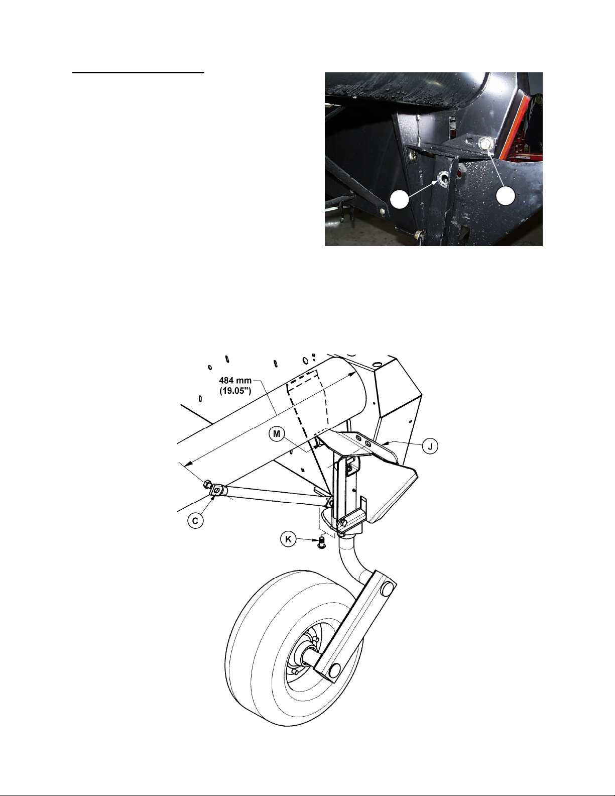
built in Model Year 2001 and later.
4. Position brace tube so that hole (C) is
484 mm (19.05”) from left endsheet as
shown. Mark this position and tack weld
a 5/8 x 1 inch black bolt from kit to main
tube. Position brace onto bolt and
confirm proper bolt position, then
remove brace from bolt and place a 5
mm (3/16”) weld completely around bolt
head.
NOTE: Ends of brace will bend slightly when initially tightened.
26 mm = 1.02”
170 mm = 6.69”
193 mm = 7.60”
LEFT ENDSHEET HOLES
LEFT ENDSHEET HOLE & WELDED BOLT
Form # 131126 Issue 11/07
2
Page 5
SET-UP INSTRUCTIONS
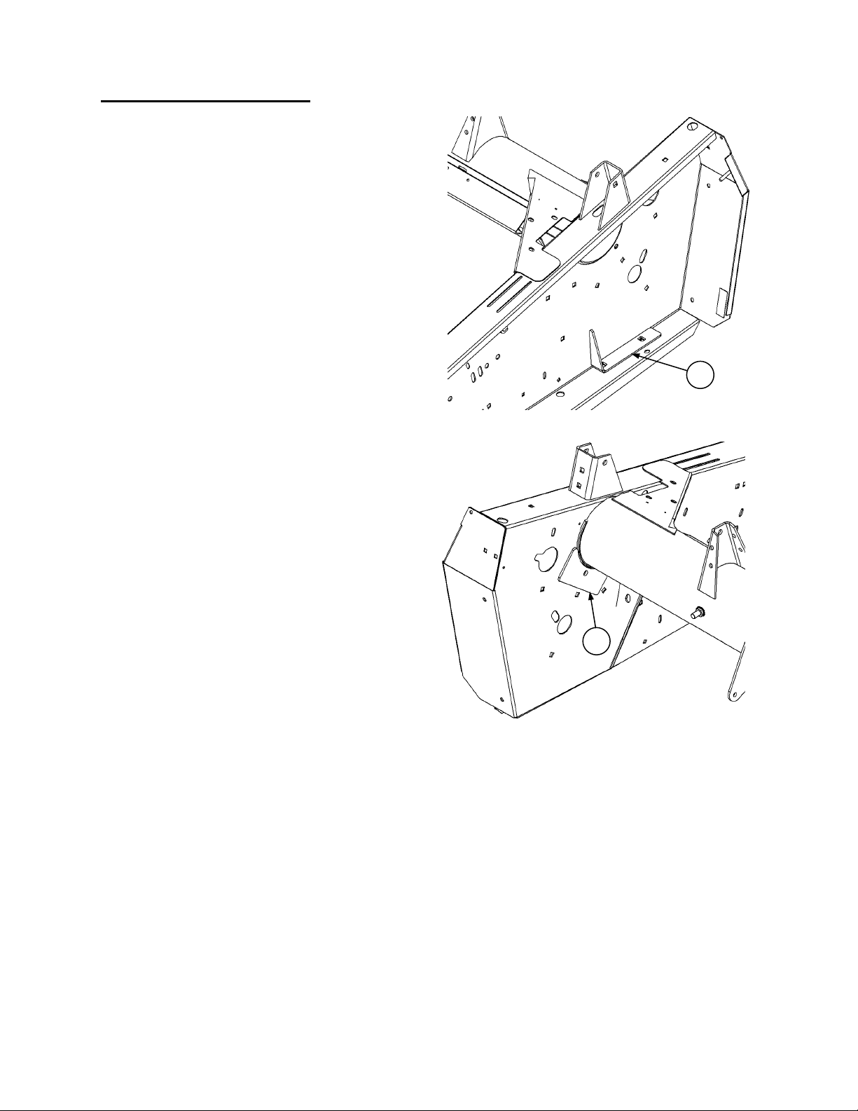
LEFT END (FORWARD) WHEEL (continued)
5. Remove left wheel assembly installed in
step 2.
6. Align holes in plate (C) (from kit) with
endsheet holes and place a 3mm (1/8”)
fillet weld all around the outside edges of
plate (C).
NOTE: Two bolts can be used in holes to
hold plate (C) during welding.
7. Align hole in plate (D) (from kit) with
endsheet hole and mate the radius of plate
with backtube. Place a 3mm (1/8”) fillet
weld around the outsides edges of plate
(D).
NOTE: A bolt can be used to hold plate (D)
in position during welding.
C
WELD OUTER SUPPORT PLATE – L/H ENDSHEET
D
WELD INNER SUPPORT PLATE – L/H ENDS SHEET
Form # 131126 Issue 11/07
3
Page 6
SET-UP INSTRUCTIONS
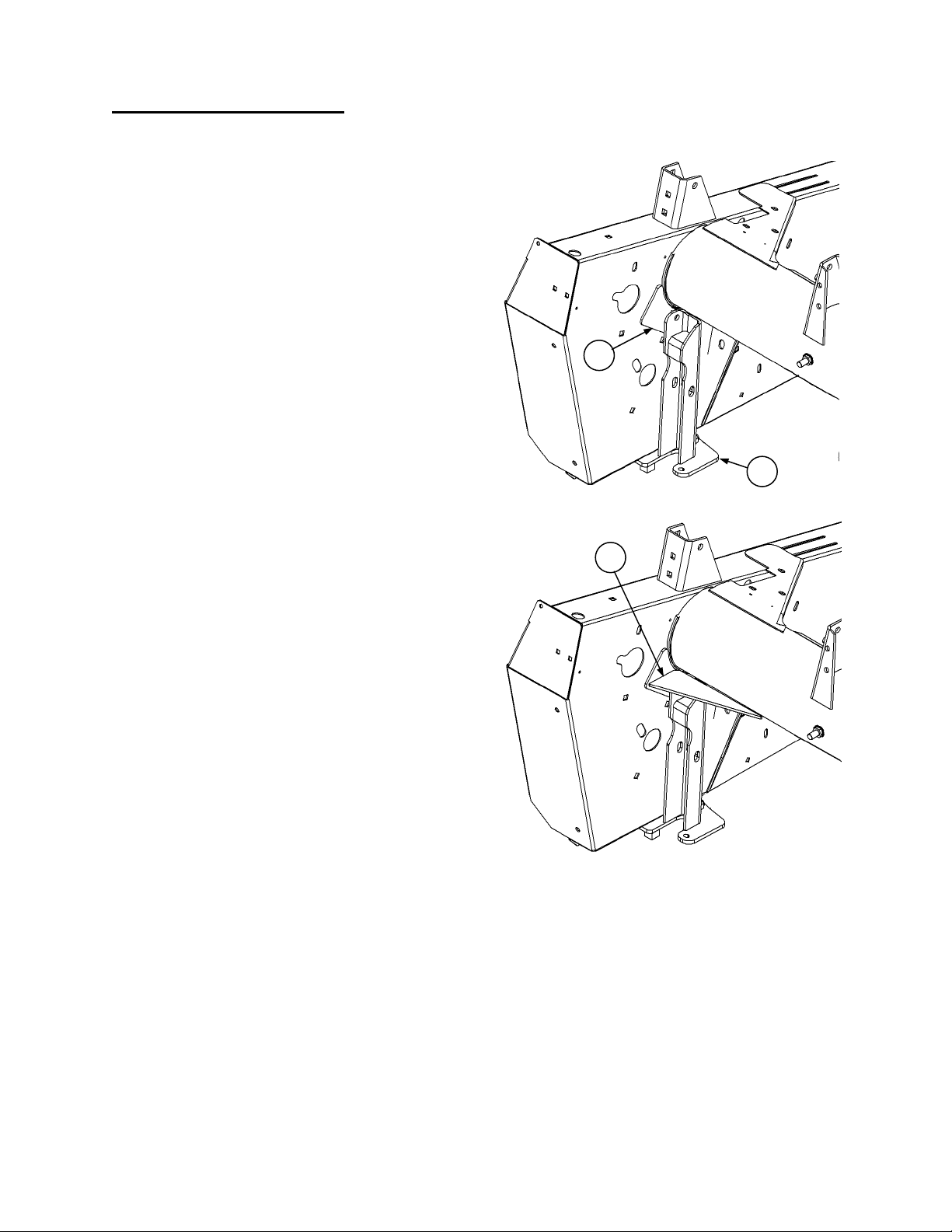
LEFT END (FORWARD) WHEEL (continued)
IMPORTANT: Steps 8-11 are for single sickle headers, for double sickle headers proceed to step 12.
8. Bolt left hand caster mount (E) into position
against inside surface of plate (D) welded in step 7
(refer to page 6 for instruction).
9. Position triangular gusset (F) (from kit) 6mm (1/4”)
above left hand caster mount and flush against
plate (D) and backtube. Tack gusset (F) in
position.
10. Remove left hand caster mount and weld gusset
(F). Place a 5mm (3/16“) fillet weld on top and
bottom edges against header backtube and plate
(D).
11. Proceed to step 15.
MOUNT LEFT HAND CASTER SUPPORT
D
E
F
POSITION & WELD GUSSET (F)
Form # 131126 Issue 11/07
4
Page 7
SET-UP INSTRUCTIONS
LEFT END (FORWARD) WHEEL
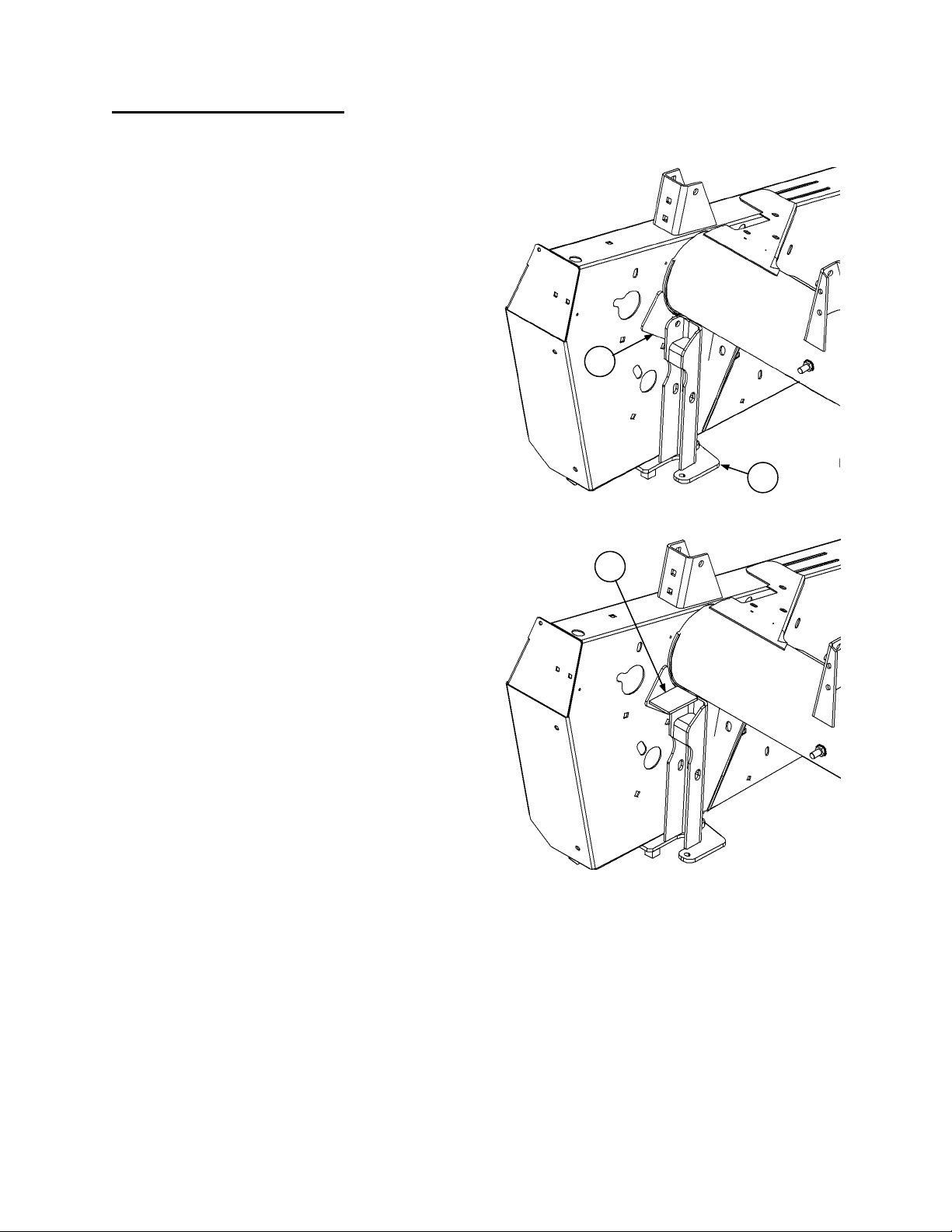
IMPORTANT: Steps 12-15 are for double sickle headers, for single sickle headers see page 4.
12. Bolt left hand caster mount (E) into position
against inside surface plate (D) welded in step 7
(refer to next page for instruction).
13. Position rectangular (100 x 68mm) gusset (G)
(from kit) 6mm (1/4”) above left hand caster mount
and flush against plate (D) and backtube. Position
the 100mm (4”) side of gusset against plate (D).
Tack gusset (G) in position.
14. Remove left hand caster mount and weld gusset
(G). Place a 3mm (1/8”) fillet weld on top and
bottom edges against header backtube, end panel
gusset and plate (D).
(continued)
D
MOUNT LEFT HAND CASTER SUPPORT
E
G
POSITION & WELD GUSSET (G)
(
END PANEL GUSSET REMOVED FOR CLARITY)
Form # 131126 Issue 11/07
5
Page 8

SET-UP INSTRUCTIONS
LEFT END (FORWARD) WHEEL
15. Install left wheel assembly as shown below:
• At the two holes in bottom flange of endsheet, use two 5/8 x 1-1/4 carriage bolts at (H) (heads
down) and 5/8 flange nuts.
• At hole in side of left endsheet, use one 5/8 x 2” hex head bolt (D), 5/8 flat washers (F) (three for
single sickle & four for double sickle headers), and 5/8 flange nut (G).
• At bolt welded to frame tube, use one 5/8 flange nut (J) to secure brace tube.
• Attach storage bracket to rear of left endsheet with two 1/2 x 1 inch short neck carriage bolts and
1/2 flange nuts at (K).
NOTE: For single sickle headers
double sickle drive headers, at top bolt, use the existing belt tension adjusting bolt to secure
bracket.
(continued)
, If not present, drill 0.531” hole (L) at dimensions shown. For
Three required for Single Sickle
Four required for Double Sickle.
LEFT WHEEL ASSEMBLY
Form # 131126 Issue 11/07
6
Page 9

SET-UP INSTRUCTIONS
RIGHT END (REAR) WHEEL
1. On bottom flange of right endsheet, drill two 0.656” holes* (C) as shown.
NOTE: Holes in bottom flange may be round or square.
* These holes will be present on headers built in Model Year 2001 and later.
38 mm = 1.50”
100 mm = 3.94”
80 mm = 3.15”
RIGHT ENDSHEET HOLES
Form # 131126 Issue 11/07
7
Page 10
SET-UP INSTRUCTIONS
RIGHT END (REAR) WHEEL
2. Attach right wheel assembly at the two holes
drilled in Step 1, using 5/8 x 1-1/4 carriage head
bolts at (K) (heads down) and 5/8 flange nuts.
Secure at gusset under frame tube with 5/8 x 11/4 carriage head bolt (M) and flange nut.
3. Drill a 0.812” diameter hole in the endsheet,
using the hole (A) in wheel assembly as a
guide. (Disassemble as required for fit-up.) This
hole will be present on headers built in Model
Year 2001 and later.
4. Mark the position for hole (B) as follows:
For double sickle drive headers: Use the rear
hole in support (J) as shown.
For single sickle drive headers: Use the forward
hole in support (J).
Drill a 0.750” diameter hole. This hole will be present on headers built in Model Year 2001 and later.
5. Position brace tube so that hole (C) is 484 mm (19.05”) from right endsheet as shown. Mark this
position and tack weld a 5/8 x 1 inch black bolt from kit to main tube. Position brace onto bolt and
confirm proper bolt position, then remove brace from bolt and place a 5 mm (3/16”) weld completely
around bolt head.
(continued)
A
B
RIGHT ENDSHEET HOLES – DOUBLE SICKLE
HEADER SHOWN
RIGHT ENDSHEET HOLES & WELDED BOLT
Form # 131126 Issue 11/07
8
Page 11

SET-UP INSTRUCTIONS
RIGHT END (REAR) WHEEL
6. Install right wheel assembly as shown below:
• Install 3/4 x 4-1/2” hex head bolt through wheel assembly and new 0.812” hole in endsheet.
Position plate (G) on outside face of endsheet and secure with 3/4 nut (E).
NOTE: If necessary, elongate hole in endsheet horizontally as required to fit.
• At new 0.75” hole in endsheet, install 5/8 x 1-1/4 hex head bolt (F) and secure with nut (H).
NOTE: For double sickle drive headers
shown. For single sickle drive headers
• At bolt welded to frame tube, use one 5/8 flange nut (L) to secure brace tube.
(continued)
use top hole in plate (G) and rear hole in support (J) as
, use lower hole in plate (G) and forward hole in support (J).
RIGHT WHEEL ASSEMBLY
Form # 131126 Issue 11/07
9
Page 12

SET-UP INSTRUCTIONS
FRONT (CUTTERBAR) WHEEL
1. At right hand header leg
2. Weld rectangular bar (A) across bottom of leg, using a 5 mm (3/16”) weld on top surface (B) both
sides as shown below. Ensure there is no weld at edges.
3. Weld two cropped bars* (C) to sides of leg, with crop towards cutterbar as shown below. Use a 5 mm
(3/16”) weld at edges (D), both sides.
* These welded bars (C) will be present on headers built in Model Year 2001 and later.
, remove skid shoe, if installed.
10 mm = 0.39”
227 mm = 8.94”
259 mm = 10.20”
R/H LEG MODIFICATIONS
Form # 131126 Issue 11/07
10
Page 13

SET-UP INSTRUCTIONS
FRONT (CUTTERBAR) WHEEL
4. Install front wheel assembly as shown below.
• Install wheel assembly over guard tips (E) at right header leg.
• Ensure clamp is seated up inside leg.
• Operate lever (F) to engage clamp on leg plate.
• If leg mounted skid shoes are required, install new shoe (G) (with higher front lip) from kit at right
header leg.
NOTE: Leg mounted skid shoes can not be installed when combine adapter is installed.
(continued)
FRONT WHEEL ASSEMBLY
Form # 131126 Issue 11/07
11
Page 14
SET-UP INSTRUCTIONS
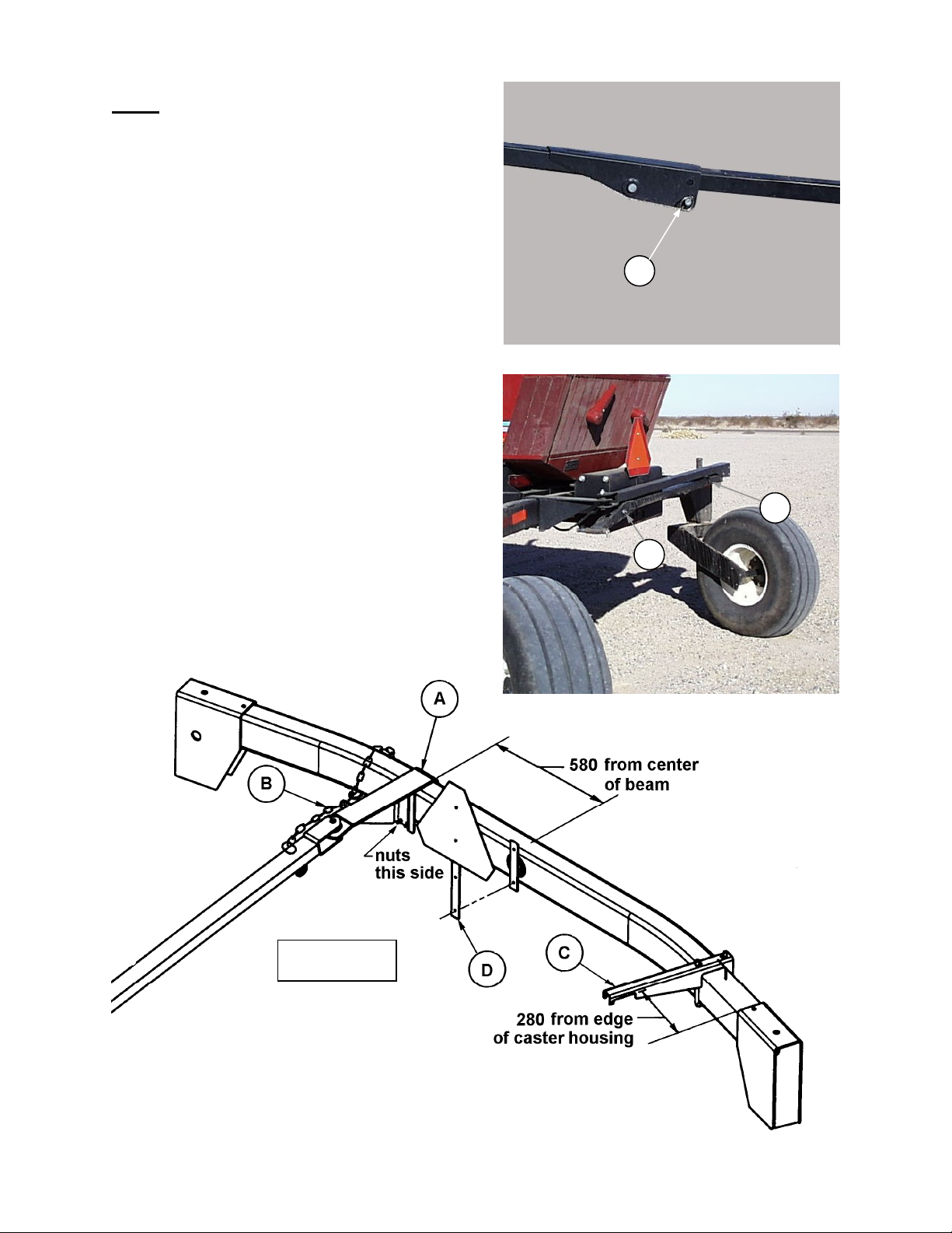
HITCH
1. Slide bracket (A) over walking beam and
position as shown below. Secure with two 5/8 x
5-1/2” hex head bolts and flange nuts.
2. Route hitch chain (B) through chain support on
bracket (A), then wrap around walking beam
and lock hook on chain.
3. Position storage bracket (C) as shown below
and secure with U-bolt and 1/2 NC flange nuts.
4. Remove SMV sign from welded mount. Attach
extension bar (D) to welded mount using new
self-tapping screws.
NOTE: Use the larger holes in bar (D) to attach
to welded mount. It may be necessary to bend
the welded mount out slightly.
5. Attach SMV sign to smaller holes in bar (D)
using the existing self-tapping bolts removed
form welded mount.
6. Remove split ring and remove lock pin from
hitch knee joint at (E).
7. Store hitch as follows: Place front section of
hitch on top of storage bracket (C) at right side
of walking beam. Fold hitch and place rear
section into notch in bottom of bracket (C).
Install pin from knee joint to lock the two
sections at (G) and secure with split ring.
E
REMOVE LOCK PIN FROM HITCH JOINT
C
G
HITCH STORAGE
580 mm = 22.84”
280 mm = 11.02”
ATTACH HITCH TO TRACTOR
Form # 131126 Issue 11/07
12
Page 15

SET-UP INSTRUCTIONS
TRANSPORT LIGHTS ON HEADER
1. Open left hand drive shield and route header section of transport wiring harness through inside of
frame tube to right endsheet.
NOTE: The end of the harness with the 6-way connector goes to the right endsheet.
NOTE: For European applications, the lamp module
referred to in steps 2 and 3 is not used. Header
harness connects directly to end sheet harness.
2. At the R/H end sheet, install lamp module and
support as follows: For Single Sickle Headers
Install at (N) with the hardware that secures the
sickle storage tube as shown at right. For Double
Sickle Headers, install at clamp (V) as shown
below.
,
N
INSTALL LAMP MODULE – Single Sickle
(EXCEPT EUROPEAN APPLICATIONS)
V
INSTALL LAMP MODULE – Double Sickle
(EXCEPT EUROPEAN APPLICATIONS)
3. Connect header harness and end sheet
harness to lamp module. Route end sheet
harness to top of end sheet through hole at reel
support arm anchor (S).
4. Install lights at R/H endsheet as shown at right,
using the hardware that secures the pivoting
amber lights. Secure harness with plastic tie at
(R). NOTE: For European applications, pivoting
amber lights are not installed. Install transport
lights using hardware provided.
NOTE: Wire colors do not match up when
connecting harness to lights. Refer to wiring
schematic on Page 15.
R
S
INSTALL LIGHTS AT END SHEET
R
S
INSTALL LIGHTS AT ENDSHEET
Form # 131126 Issue 11/07
13
Page 16

SET-UP INSTRUCTIONS
(
)
TRANSPORT LIGHTS ON HEADER
5. Install lights at R/H reel support arm using ½ x
1 inch carriage bolts and flange nuts as shown.
Mounting for 2001 and newer headers shown
in top photo. For pre-2001 headers, light mount
is attached as shown in second photo.
NOTE: For headers with floating divider option, a
different light mounting bracket is required. See
instructions packaged with dividers.
6. For 2001 and newer headers, install harness
guard as shown at (A). For pre-2001 header
install harness guard as shown at (B).
7. Install harness guard holder (G) on reel arm as
shown. Secure holder with 5/8 x 1 inch hex
head bolt and lock nut. Route harness up
inside reel support arm and over bolt (D). Pass
harness through guard to lights and make the
connections. Secure harness with plastic tie at
(C) (see inset, top photo).
NOTE: Wire colors do not match up when
connecting harness to lights. Refer to wiring
schematic on page 15.
D
INSTALL GUARD HOLDER
8. For single sickle drive headers
and flange nut as shown below left.
For double sickle drive headers
from bottom of sign as shown at (E). Also drill a 0.406” hole in RH reel arm located 7 ½” (190 mm)
rearward of reel lift cylinder pin (F), and 3/8” (10 mm) above centerline of reel lift cylinder pin (F).
Attach sign with spacer, 3/8 x 1 ¾ carriage bolt and flange nut as shown below right.
(continued)
A
INSTALL LIGHTS & HARNESS GUARD AT
R/H REEL ARM
B
G
INSTALL LIGHTS & HARNESS GUARD AT
R/H REEL ARM - Pre-2001 Header
, attach Slow Moving Vehicle sign with spacer, 3/8 x 1 ¾ carriage bolt
, drill a 0.406” hole in SMV sign, centered on base and 2.16” (55 mm)
C
E
F
INSTALL SMV SIGN
SINGLE SICKLE DRIVE HEADERS
Form # 131126 Issue 11/07
14
(DOUBLE SICKLE DRIVE HEADERS)
INSTALL SMV SIGN
Page 17

SET-UP INSTRUCTIONS
TRANSPORT LIGHTS ON HEADER
9. At left end, route harness (G) as shown and
engage tab of 4-way connector in hole in
endsheet at (H) for storage. Ensure harness
will reach to hitch section before securing.
10. Secure harness at clamp (J) and cable tie at
(K) as shown. Attach harness ground wire at
bolt for clamp (J) with 3/8 nut provided.
(continued)
K
J
G
H
G
HEADER HARNESS – LEFT END
DOUBLE SICKLE
K
H
HEADER HARNESS – LEFT END
SINGLE SICKLE
CONNECTIONS TO LIGHTS
Form # 131126 Issue 11/07
15
Page 18

SET-UP INSTRUCTIONS
AROU
REFLECTORS ON HEADER
1. Add eight amber reflectors to header as shown below:
FRAME TUBE AT CENTER OPENING
LEFT END – TWO REFLECTORS
WRAP THREE REFLECTORS
ND CENTER OF REEL TUBE
RIGHT END – TWO REFLECTORS
DOUBLE SICKLE HEADER
RIGHT END – TWO REFLECTORS
SINGLE SICKLE HEADER
Form # 131126 Issue 11/07
16
Page 19

SET-UP INSTRUCTIONS
RE-ROUTE HEADER HOSES AND HARNESS
1. At left header leg, remove reel lift hose and
header wiring harness from their clamped
position at (A). Remove female 1/4” quick
coupler from reel lift hose.
2. Re-route reel lift hose and header wiring
harness into v-channel under main tube and out
rectangular hole at (B). Reinstall quick coupler
on reel lift hose.
3. Remove clamp from draper drive hoses at (B).
B
A
4. Install new support (C) as shown, using existing
hardware. Remove female quick coupler from
draper drive hose and install on support (C)
with dished washer (D) positioned as shown
below. Install insulated clip (E) with 3/8 x 3/4”
carriage bolt and flange nut to attach reel lift
hose and header wiring harness.
5. Connect harness extension (F) from kit [1200
mm, (48”) long] to header harness and tie to
draper drive hose and reel lift hose as shown.
F
HOSE / HARNESS ROUTING
C
F
HOSE / HARNESS ROUTING
E
D
HOSE / HARNESS ROUTING
Form # 131126 Issue 11/07
17
Page 20

SET-UP INSTRUCTIONS
RE-ROUTE HEADER HOSES AND HARNESS
6. At right header leg, remove reel drive hoses
from the existing mounting bracket. Remove
bracket from header.
7. Install hoses on new support (G) and mount
support to header leg as shown with two 3/8 x
3/4 carriage bolts and flange nuts (nuts inside
leg).
(continued)
G
REEL DRIVE HOSE MOUNT
REEL DRIVE HOSE MOUNT
Form # 131126 Issue 11/07
18
Page 21

SET-UP INSTRUCTIONS
REPOSITION TRACTOR HOSES & HARNESS
1. Remove female coupler from draper drive hose
at tractor left side.
2. Install 900 mm (35”) long hose (A) where
coupler was removed. Use existing dished
washer between hose (A) and bracket.
3. Attach 1/2 NPT 45° elbow (G) to hose (A).
4. Position new bracket (B) on tractor as shown at
right and tighten bolts to clamp in place.
5. Attach female coupler (C), removed above, to
hose (A) at new bracket, using dished washer
between bracket and coupler as shown.
6. Move reel lift coupler (D) from existing bracket
to new bracket. Install 1/4 NPT 45° elbow (H)
as shown. Use dished washer between bracket
and coupler as shown.
7. Insert two-prong connector
(E) from existing
tractor wiring harness through smaller hole in
bracket. NOTE: Three-prong connector (F) is
from the tractor section of the transport
harness, which will be installed on the next
page. When installed, clamp both harnesses to
bracket.
NOTE: If tractor has optional hydraulic reel fore-aft
kit installed, move fore-aft coupler mount to inboard
set of holes as shown below.
B
C
F
A
D
E
REPOSITION TRACTOR COUPLERS &
HARNESS
FORE-AFT
COUPLERS
TRANSPORT
COUPLERS
TRANSPORT LIGHTS ON TRACTOR
1. Bolt lights to left tractor spring anchor as shown.
2. Repeat at right side.
INSTALL TRANSPORT LIGHTS ON
TRACTOR
Form # 131126 Issue 11/07
19
Page 22

SET-UP INSTRUCTIONS
TRANSPORT HARNESS – TRACTOR SECTION
1. Route tractor section of transport wiring harness as shown below. Route over frame cross members
along left side of tractor and secure with cable ties for best protection and appearance.
2. Connect harness to hitch harness at rear of tractor
TRANSPORT HARNESS
(TRACTOR SECTION)
Form # 131126 Issue 11/07
20
Page 23

SET-UP INSTRUCTIONS
CENTER LINK CLIP
1. For tractors with mechanical center link, install
spring clip (A) as shown at right to retain link in
raised position during hook-up.
• Remove pin from center link at tractor.
• Install spring (A) as shown (spring outlined
for photo clarity).
• Replace pin through frame bracket, spring
coil and center link ball end. Secure with hair
pin.
• Looped end of spring engages under frame
plate at (B).
HAY CONDITIONER STORAGE COMPONENTS
If header has a hay conditioner, install components
for support of conditioner during transport and
conversion to and from transport.
1. Attach bracket (C) and transfer chain (D) to right
hand tractor floorboard as at right. This chain is
only used during conversion to and from
transport.
NOTE: For high clearance tractors (XX52
models) add the short extension chain provided
to achieve proper length (see Parts Catalog page
50/51 for hardware used).
2. Attach bracket (E) for transfer chain (D) to right
side of conditioner top sheet using longer bolts
provided as shown below right.
3. Attach bracket (F) to inside of header right leg as
shown below. This bracket is used to support
conditioner in transport by engaging conditioner
support chain (G).
A
CENTER LINK SPRING CLIP
ATTACH TRANSFER CHAIN
E
B
C
D
F
G
ATTACH TRANSFER CHAIN BRACKET
TO CONDITIONER
SUPPORT CHAIN BRACKET
Form # 131126 Issue 11/07
21
Page 24

SET-UP INSTRUCTIONS
WEIGHT BOX WHEELS & HITCH
For units with the optional wheels and hitch package for the front end weight box:
1. Slide strap (A) into V-channel inside box (accessible from the bottom) and bolt hitch to weight box as
shown, using two 5/8 x 1-1/4 hex head bolts (A) and lockwashers (C). NOTE: Welded nuts on strap
(A) go to the inside.
2. Install two 5/8 x 1-1-4 carriage head bolts (B) and secure with 5/8 flange lock nuts (D) as shown.
(OPTION)
3. Slide wheel axles into tubes in weight box and tighten 1/2 x 2 hex head bolts (E) through welded nuts
and into axles to secure the assemblies.
Form # 131126 Issue 11/07
22
Page 25

TRANSPORT SAFETY
ATTACHING TO TOWING VEHICLE
CAUTION: To avoid bodily injury and/or machine damage caused by loss of control:
1. To ensure adequate braking performance and control, do not tow with a vehicle weighing less
than 5000 lbs. (2300 kg).
2. When towing with windrower tractor, weight box MUST be installed on front linkage to provide
adequate stability and control.
3. To increase header stability in transport, ensure that reel is down and moved back on support
arms to the 10
th
hole from the rear or further. For headers with hydraulic reel fore-aft, never
connect the fore-aft couplers to each other. This would complete the circuit and allow the reel
to creep forward in transport, resulting in instability.
4. Check that all latches and pins are properly secured in transport position at wheel supports,
hitch and cutterbar support.
5. Check tire condition and pressure prior to transporting.
6. If towing with vehicle other than windrower tractor, connect hitch to towing vehicle with a
proper hitch pin with a spring locking pin or other suitable fastener.
7. Attach hitch chain to towing vehicle. Adjust chain length to remove all slack except what is
needed for turns.
8. Ensure lights are functioning properly, and clean the slow moving vehicle emblem and other
reflectors.
TOWING THE HEADER
CAUTION: THIS IS INTENDED AS A LOW SPEED TRANSPORT. To avoid bodily injury
and or machine damage caused by loss of control:
1. Do not exceed 19 mph (30 km/h). Reduce transport speed for slippery or rough conditions.
2. Turn corners only at very low speeds [5 mph (8 km/h) or less].
3. Obey all highway traffic regulations in your area when transporting on public roads. Use
flashing amber lights unless prohibited by law.
Form # 131126 Issue 11/07
23
Page 26

CONVERTING TO TRANSPORT
CONVERTING FROM FIELD POSITION
TO TRANSPORT
1. On a level area, stop tractor and engage park brake.
WARNING: To avoid injury or caused by machine tip-over, move reel back on support
arms before converting to transport. Do not move reel forward while machine is in
transport.
2. Move reel back on support arms to the 10
Aft" in Header Operator’s Manual for adjustment details.
3. Lower reel fully. NOTE: To prevent damage to reel support arms, do not transport with reel props
engaged.
4. Raise header fully.
DANGER: To avoid bodily injury or death from unexpected start-up or fall of raised
header, stop engine, remove key and engage header lift cylinder stops before going
under header for any reason.
NOTE: Steps 5 through 10 are for headers with hay
conditioner. For headers without hay conditioner, go
to Step 11.
5. Install transfer chain (A) between conditioner
and tractor R/H floorboard.
6. Remove header lift cylinder stops and lower
header until cutterbar is approximately 4 inches
(100 mm) from ground.
7. Move conditioner support chain (B) (the chain
attached to conditioner R/H shoe) from pin (C)
located on inside of tractor leg to support (D) on
header leg.
th
hole from the rear or further. See "Reel Position - Fore &
A
ATTACH TRANSFER CHAIN
C
B
DISCONNECT SUPPORT CHAIN
Form # 131126 Issue 11/07
24
SUPPORT CHAIN BRACKET ON HEADER
D
B
Page 27

CONVERTING TO TRANSPORT
8. Raise header fully.
DANGER: To avoid bodily injury or
death from unexpected start-up or fall of
raised header, stop engine, remove key
and engage header lift cylinder stops
before going under header for any reason.
9. Remove transfer chain (A) from top of conditioner
and store at (E).
10. Disconnect conditioner float spring chain (F) on
left side of conditioner.
11. Remove pins (G) from lower header legs.
E
A
DETACH AND STORE TRANSFER CHAIN
F
DISCONNECT FLOAT SPRING
G
REMOVE LOWER LEG PINS
Form # 131126 Issue 11/07
25
Page 28

CONVERTING TO TRANSPORT
12. Lower left wheel into transport position and secure latch (A) as shown.
A
LEFT WHEEL – TRANSPORT POSITION
13. Lower right wheel into transport position and secure latch (B) in notch in plate as shown.
B
RIGHT WHEEL – TRANSPORT POSITION
Form # 131126 Issue 11/07
26
Page 29

CONVERTING TO TRANSPORT
14. Install front transport wheel at cutterbar, aligned with R/H header leg as follows:
• Install wheel assembly over guard tips (E) at right header leg.
• Ensure clamp is seated up inside leg.
• Operate lever (F) to engage clamp on leg plate.
INSTALL FRONT WHEEL AT CUTTERBAR
15. Remove “L” pin (B), both sides and detach float
springs.
16. Disengage header lift cylinder stops.
17. Be sure area is clear of bystanders, then start
engine. Retract lift cylinders to lower header
onto transport wheels.
B
DETACH FLOAT SPRINGS
Form # 131126 Issue 11/07
27
Page 30

CONVERTING TO TRANSPORT
18. Disconnect driveline from header shaft and
store at (A).
19. Disconnect draper drive hoses at left side and
couple together at (B) and at header.
20. Disconnect reel lift hose and cap at (C) and at
header.
21. For headers with hydraulic reel fore-aft,
disconnect hoses and cap lines.
WARNING: For headers with hydraulic
reel fore-aft, never connect the header
fore-aft couplers to each other. This
would complete the circuit and allow
the reel to creep forward in transport, resulting
in instability.
22. Detach electrical harnesses at (D).
23. Disconnect reel drive hoses at right side.
Couple together at (E) and cap at header.
24. Detach center link at header (F). If necessary,
adjust length of center link to release load on
front pin.
D
B
C
A
DETACH DRIVELINE, HOSES & HARNESS
E
25. Slowly back tractor away from header. If hay
conditioner is attached, watch clearances at left
and right sides.
26. Remove pins from linkage mounts on weight
box. Pick up weight box on tractor lift linkage
and raise fully
. Install pins (G), ensuring that
DETACH & STORE REEL DRIVE HOSES
they engage U-bracket in lift linkage, both
sides. Install lynch pin through welded nut and
secure with ring of lynch pin over flange on pin
(G) as shown.
27. Engage header lift cylinder stops (H).
H
G
ATTACH WEIGHT BOX TO TRACTOR
ENGAGE LIFT CYLINDER STOPS
Form # 131126 Issue 11/07
28
Page 31

CONVERTING TO TRANSPORT
28. Back the tractor close to the left end of the
header.
29. Remove lock pin on tow hitch and swing hitch
out from storage position toward header. Attach
hitch to left transport wheel support at (A) and
secure with split ring.
30. Connect electrical harness from hitch to header
at (B).
31. Drive tractor ahead until hitch falls straight.
32. Install lock pin under hitch knee joint at (C) and
secure with split ring.
33. Do a walk-around check on the following items:
Front wheel lock engaged.
Warning lights on tractor and header are
clean and working.
Outer wheels latched correctly.
SMV sign, and reflectors on reel, header
tube and endsheets are clean and visible.
Hitch pin installed and locked with split ring.
Hitch knee joint pin installed and locked with
split ring.
Weight box pins installed and locked with
lynch pins.
Header lift cylinder stops engaged.
A
B
ATTACH HITCH & CONNECT HARNESS
C
LOCK HITCH JOINT WITH PIN
Form # 131126 Issue 11/07
29
Page 32

CONVERTING TO FIELD
CONVERTING FROM TRANSPORT POSITION TO FIELD
1. On a level area, stop tractor and engage park
brake.
2. Remove pins (G) at weight box links, both
sides.
3. Move header lift cylinder stops to storage
position (H).
4. Remove split ring and detach hitch pin at (A).
5. Disconnect wiring harness at (B) and store
header harness by engaging clip on 4-way
connector in hole on back panel of left
endsheet.
G
REMOVE WEIGHT BOX PINS
H
STORE HEADER LIFT CYLINDER STOPS
A
B
DETACH HITCH & HARNESS
STORE HEADER HARNESS
Form # 131126 Issue 11/07
30
Page 33

CONVERTING TO FIELD
6. Remove split ring and remove lock pin from
hitch knee joint at (C).
7. Store hitch as follows: Place front section of
hitch on top of storage bracket (D) at right side
of walking beam. Fold hitch and place rear
section into notch in bottom of bracket (D).
Install pin from knee joint to lock the two
sections at (E) and secure with split ring.
8. Drop weight box off tractor linkage in a suitable,
level location. Fully retract header lift cylinders.
9. Slowly drive tractor forward so that lift linkage
enters header legs. Continue to drive slowly
forward until linkage contact support plate in the
lower header leg, and header nudges forward.
Stop engine, set park brake and remove key.
10. Connect center link to header at (F).
C
REMOVE LOCK PIN FROM HITCH JOINT
D
E
HITCH STORAGE
11. Connect driveline to header drive shaft.
12. Connect reel lift hose, draper drive hoses and
electrical harnesses from tractor to header at
left side.
13. Connect reel drive hoses from tractor to header
at right side.
14. Raise header fully.
NOTE: Steps 15 through 20 are for headers with
hay conditioner. For headers without hay
A
conditioner, go to Step 21.
15. Connect conditioner transfer chain (A) to right
side of conditioner.
Form # 131126 Issue 11/07
31
ATTACH TRANSFER CHAIN
Page 34

CONVERTING TO FIELD
16. Lower header until cutterbar is approximately 4
inches (100 mm) from ground.
17. Move conditioner support chain (B) (the chain
attached to conditioner R/H shoe) from support
(D) on header leg to pin (C) inside of tractor leg.
C
B
CONNECT SUPPORT CHAIN TO TRACTOR
18. Raise header fully.
DANGER: To avoid bodily injury or
death from unexpected start-up or fall
of raised header, stop engine, remove
key and engage header lift cylinder
stops before going under header for any
reason.
19. Remove transfer chain (A) from top of
conditioner and store at (E).
20. Connect conditioner float spring chain (F) on
left side of conditioner.
D
B
REMOVE SUPPORT CHAIN FROM BRACKET
E
A
DETACH AND STORE TRANSFER CHAIN
F
CONNECT FLOAT SPRING
Form # 131126 Issue 11/07
32
Page 35

CONVERTING TO FIELD
21. Install pins (G) in lower header legs, engaging U-
bracket in tractor lift linkage.
22. Install “L” pin (B), both sides to engage float
springs.
23. Raise left transport wheel to field storage
position. Install hitch pin, removed in Step 4, at
(A) to lock the wheel in storage.
G
REMOVE LOWER LEG PINS
B
ATTACH FLOAT SPRINGS
A
LEFT WHEEL – FIELD STORAGE
Form # 131126 Issue 11/07
33
Page 36

CONVERTING TO FIELD
24. Raise right transport wheel to field storage position, engaging caster tube bracket on thickness of
support plate at (C).
C
RIGHT WHEEL – FIELD STORAGE
25. Operate lever (F) to release clamp on front wheel and lift off guards (E). For units with optional hitch
on weight box, cutterbar wheel may be stored on weight box, engaging cutterbar clamp in slot of hitch
handle as shown.
REMOVE FRONT WHEEL FROM CUTTERBAR
FRONT WHEEL STORAGE
26. Move reel forward to desired position.
Form # 131126 Issue 11/07
34
Page 37

MAINTENANCE / SERVICE
GREASING: 500 Hours or Annually
Outer Wheel Casters (A) & (B) – two fittings.
A
Wheel Hub Bearings (C) – three fittings
Optional Weight Box Wheel Hubs (D) – two fittings
B
C
D
Form # 131126 Issue 11/07
35
Page 38

MAINTENANCE / SERVICE
Wheel Bolts
Check and tighten wheel bolts after the first 10
hours of operation and every 100 hours thereafter.
Whenever a wheel is removed and re-installed,
check torque after one hour of operation.
Maintain torque of 80 to 90 ft.lbs. (110 to 120 N⋅m)
Follow the proper bolt tightening sequence shown.
NOTE: When installing wheel, be sure valve stem
(C) points away from wheel support.
Tire Inflation
Check tire pressure daily
on cutterbar tire and 70 psi (480kPa) on L/H and R/H
tires.
seat the bead on the rim. Replace the tire if it has
a defect. Replace a wheel rim, which has cracks,
wear or severe rust. Never weld a wheel rim. Make
sure all the air is removed from a tire before
removing the tire from a rim. Never use force on
an inflated or partially inflated tire. Make sure the
tire is correctly seated before inflating to
operating pressure.
Do not remove, install or make repairs to a tire on
a rim unless you have the proper equipment and
experience to perform the job. Take the tire and
rim to a qualified tire repair shop. If the tire is not
in correct position on the rim, or is too full of air,
the tire bead can loosen on one side, causing air
to leak at high speed and with great force. An air
leak of this nature can thrust the tire in any
direction, endangering anyone in the area.
(A) - Use a safety cage if available.
(B) - Do not stand over tire. Use a clip-on chuck and
extension hose.
. Maintain 100 psi (690 kPa)
WARNING: Service tires safely. A tire
can explode during inflation and cause
serious injury or death. Never increase
air pressure beyond 35 psi (241 kPa) to
C
6
1
3
5
4
2
BOLT TIGHTENING SEQUENCE
SERVICE TIRES SAFELY
Form # 131126 Issue 11/07
36
Page 39

Model 972 Harvest Header
21’ & 25’ TRANSPORT OPTION
REPAIR PARTS
CONTENTS
Hitch & Header Transport Lights................................................................................................................ 38, 39
Left Hand Transport Wheel........................................................................................................................40, 41
Cutterbar Transport Wheel.........................................................................................................................42, 43
Right Hand Transport Wheel......................................................................................................................44, 45
Transport Weight Box ................................................................................................................................46, 47
Tractor Mounted Transport Parts & Header Hose Supports...................................................................... 48, 49
Hay Conditioner Supports..........................................................................................................................50, 51
Decals ..............................................................................................................................................................52
Numerical List ..................................................................................................................................................53
ABBREVIATIONS
L/H – left hand (Determined from Operator’s
position, facing forward.)
R/H – right hand
I.D. – inside diameter
O.D. – outside diameter
A/R – as required (quantity varies with
header size)
NOTE: Common hardware is not illustrated. Alphabetic references are used to designate position and
description of these items. When ordering, be sure the complete and proper serial number is given.
SERIAL NUMBER BREAKS
The side of the serial number on which the dash (-) appears determines whether the part is used “up to”
or “after” the serial number given.
Example: -74924 Used on machines up to and including serial number 74924.
74925- Used on machines including and after serial number 74925.
REF – reference, part number called up
elsewhere in catalog
SUB – Substitute (Revised design may be
used to repair previous design when
stock is depleted.)
NC – national coarse thread
NF – national fine thread
Form # 131126 Issue 11/07
37
Page 40

HITCH & HEADER TRANSPORT LIGHTS
Form # 131126 Issue 11/07
38
Page 41

REF PART DESCRIPTION QTY SERIAL
1 131117 HITCH – front................................................................................................1
2 131001 HITCH – rear.................................................................................................1
3 REF MOUNT – walking beam to hitch, see Tractor Mounted Transport Parts.....1
4 113532 CLAMP – hose..............................................................................................1
5 131128 HARNESS – wiring, hitch section .................................................................1
6 18629 PIN – clevis, 3/4” x 95 mm ............................................................................2
7 118137 RING – split...................................................................................................2
8 131043 PIN – hitch, 3/4 x 7 inch................................................................................1
9 REF CASTER – see Left Hand Transport Wheel .................................................1
10 113519 SUPPORT – rear lamp .................................................................................1
11 113518 LAMP – amber/red, ECE/SAE ......................................................................2
12 113579 MODULE – lamp, except European .............................................................1
13 113520 SUPPORT – lamp module, except European...............................................1
14 113524 HARNESS – wiring, module to lamps...........................................................1
15 131080 HARNESS – wiring, header section (hitch to module) .................................1
16 39272 CLIP – insulated............................................................................................3
17 113569 GUARD – harness ........................................................................................1
18 113572 HOLDER – harness guard............................................................................1
19 117056 SUPPORT – front lamp, with amber reflector...............................................1
20 43843 SIGN – slow moving vehicle .........................................................................1
21 31061 CONNECTOR KIT – 4-way, includes male and female connectors.........A/R
22 18608 PIN – cotter, 3/16” x 1-1/2 inch .....................................................................1
23 13710 SPACER – tube ............................................................................................1
A 30896 BOLT – hex head, 3/4 NC x 3-1/2 inch
B 102636 NUT – side lock, 3/4 NC
C 50186 NUT – lock, 1/2 NC, distorted thread
D 30228 NUT – lock, smooth flange, 3/8 NC distorted thread
E 21868 BOLT – round head, square neck, 1/2 NC x 1 inch
F 135020 SCREW – truss head, #8 NC x 3/4 inch
G 135021 NUT – keps lock, #8 NC
H 50163 BOLT – hex head, 5/8 NC x 5-1/2 inch
J 21580 BOLT – hex head, 1/4 NC x 1/2 inch
K 21455 NUT – serrated flange lock, 1/4 NC
L 113611 BOLT – hex head, 5/8 NC x 1 inch
M 18666 NUT – lock, 5/8 NC distorted thread
N 50076 BOLT – hex head, flange, 3/8 NC x 5/8 inch
P 50225 NUT – flange, lock, 5/8 NC
R 50197 BOLT – round head, square neck, 3/8 NC x 1-3/4 inch
NUMBER NUMBER
NOTE: For Tractor-mounted lights, see Tractor Mounted Transport Parts, page 48
HITCH & HEADER TRANSPORT LIGHTS
Form # 131126 Issue 11/07
39
Page 42

LEFT HAND TRANSPORT WHEEL
Form # 131126 Issue 11/07
40
Page 43

LEFT HAND TRANSPORT WHEEL
REF PART DESCRIPTION QTY SERIAL
NUMBER NUMBER
1 131012 CASTER – left hand ..................................................................................... 1
2 131021 SHAFT – caster, left hand ............................................................................ 1
3 131015 MOUNT – left hand caster............................................................................ 1
4 131022 TUBE – diagonal ..........................................................................................1
5 131023 LATCH – left hand wheel .............................................................................1
6 19739 SPRING – latch ............................................................................................1
7 18624 PIN – clevis, 5/8” x 70 mm ........................................................................... 1
8 13125 PIN – hair......................................................................................................1
9 18671 FITTING – grease, 1/4 –28 .......................................................................... 1
10 30517 CONE – bearing, with seal, inner .................................................................1
11 41982 HUB – with bearing cups & grease fitting..................................................... 1
12 21376 CONE – bearing, with seal, outer................................................................. 1
13 21540 WASHER – hardened ..................................................................................1
14 18648 PIN – cotter, 3/16 x 1-1/4 inch...................................................................... 1
15 5512 NUT – hex, slotted, 3/4 NF........................................................................... 1
16 30520 CAP – dust ................................................................................................... 1
17 103697 RIM – 10 x 6 x 6 ...........................................................................................1
113020 VALVE STEM............................................................................................... 1
18 103696 TIRE – 20.5 x 8 x 10, 12 ply ......................................................................... 1
19 18916 BOLT – wheel, 9/16-18 NF x 1-1/4 inch....................................................... 6
20 131024 SUPPORT – storage, left hand wheel.......................................................... 1
21 100200 WASHER – flat ............................................................................................ 4
22 129819 PLATE – welded, L/H endsheet (inboard surface) ..................................1
23 129820 GUSSET – welded, L/H endsheet (outboard surface)............................. 1
24 129822 GUSSET – welded, single knife headers (triangular).............................. 1
25 128824 GUSSET – welded, double knife headers (square)................................. 1
A 50186 NUT – lock, flange, 1/2 NC
B 21578 BOLT – hex head, 1/2 NC x 2-1/4 inch
C 50225 NUT – lock, flange, 5/8 NC
E 20077 BOLT – hex head, 3/8 NC x 1 inch
F 18637 WASHER – lock, 3/8 ID
G 21868 BOLT – round head, square neck, 1/2 NC x 1 inch
H 21587 BOLT – hex head, 5/8 NC x 2 inch
K 103562 BOLT – round head, square neck, 5/8 NC x 1-1/4 inch
Form # 131126 Issue 11/07
41
Page 44

CUTTERBAR TRANSPORT WHEEL
Form # 131126 Issue 11/07
42
Page 45

REF PART DESCRIPTION QTY SERIAL
1 131054 SUPPORT – front wheel .............................................................................. 1
2 131063 SUPPORT – cutterbar..................................................................................1
3 131062 LATCH – front wheel .................................................................................... 1
4 45157 WASHER – dished .......................................................................................1
5 9415 SPRING – latch............................................................................................ 1
6 30517 CONE – bearing, with seal, inner................................................................. 1
7 41982 HUB – with bearing cups & grease fitting..................................................... 1
8 21376 CONE – bearing, with seal, outer.................................................................1
9 21540 WASHER – hardened .................................................................................. 1
10 5512 NUT – hex, slotted, 3/4 NF........................................................................... 1
11 18648 PIN – cotter, 3/16 x 1-1/4 inch...................................................................... 1
12 30520 CAP – dust ................................................................................................... 1
13 103696 TIRE – 20.5 x 8 x 10, 12 ply ......................................................................... 1
14 103697 RIM – 10 x 6 x 6 ...........................................................................................1
113020 VALVE STEM............................................................................................... 1
15 18916 BOLT – wheel, 9/16-18 NF x 1-1/4 inch....................................................... 4
16 113278 HANDLE – wheel.......................................................................................... 1
17 113576 BOLT – wheel handle, 9/16-18 NF x 1-1/2 inch........................................... 2
18 131031 SHOE – skid................................................................................................. 1
A 50225 NUT – lock, flange, 5/8 NC
B 21565 BOLT – hex head, 1/2 NC x 1-3/4 inch
C 50186 NUT – lock, flange, 1/2 NC
NUMBER NUMBER
CUTTERBAR TRANSPORT WHEEL
Form # 131126 Issue 11/07
43
Page 46

RIGHT HAND TRANSPORT WHEEL
Form # 131126 Issue 11/07
44
Page 47

REF PART DESCRIPTION QTY SERIAL
1 131092 CASTER – right hand wheel ........................................................................1
2 131081 TUBE – pivot, right hand wheel....................................................................1
3 131086 MOUNT – right hand wheel..........................................................................1
4 131022 TUBE – diagonal ..........................................................................................1
5 131090 PLATE – right hand wheel............................................................................ 1
6 131091 LATCH – right hand wheel ........................................................................... 1
7 18671 FITTING – grease, 1/4 –28 .......................................................................... 1
8 30441 WASHER – hardened, 5/8 ID.......................................................................1
9 30517 CONE – bearing, with seal, inner................................................................. 1
10 41982 HUB – with bearing cups & grease fitting..................................................... 1
11 21376 CONE – bearing, with seal, outer................................................................. 1
12 21540 WASHER – hardened ..................................................................................1
13 5512 NUT – hex, slotted, 3/4 NF........................................................................... 1
14 18648 PIN – cotter, 3/16 x 1-1/4 inch...................................................................... 1
15 30520 CAP – dust ................................................................................................... 1
16 103696 TIRE – 20.5 x 8 x 10, 12 ply ......................................................................... 1
17 103697 RIM – 10 x 6 x 6 ...........................................................................................1
113020 VALVE STEM............................................................................................... 1
18 18916 BOLT – wheel, 9/16-18 NF x 1-1/4 inch....................................................... 1
A 50225 NUT – lock, flange, 5/8 NC
B 21733 BOLT – hex head, 3/4 NC x 4-1/2 inch
C 18689 NUT – lock, 3/4 NC
D 21585 BOLT – hex head, 5/8 NC x 1-1/4 inch
E 21575 BOLT – hex head, 1/2 NC x 1 inch
F 50186 NUT – lock, flange, 1/2 NC
G 103562 BOLT – round head, square neck, 5/8 NC x 1-1/4 inch
NUMBER 15’/18’/21’/25’ NUMBER
RIGHT HAND TRANSPORT WHEEL
Form # 131126 Issue 11/07
45
Page 48

TRANSPORT WEIGHT BOX
Form # 131126 Issue 11/07
46
Page 49

TRANSPORT WEIGHT BOX
REF PART DESCRIPTION QTY SERIAL
NUMBER NUMBER
1 131034 FRAME – weight box.................................................................................... 1
2 131043 PIN – hitch, 3/4 x 7 inch ...............................................................................2
3 50193 PIN – lynch ...................................................................................................2
4 B3089 WHEELS & HITCH KIT – for weight box.................................................OPT
Kit available through WholeGoods only
5 131073 HITCH – weight box ..................................................................................... 1
6 131078 STRAP – hitch.............................................................................................. 1
7 30517 CONE – bearing, with seal, inner................................................................. 2
8 41982 HUB – with bearing cups & grease fitting..................................................... 2
9 21376 CONE – bearing, with seal, outer.................................................................2
10 21540 WASHER – hardened ..................................................................................2
11 5512 NUT – hex, slotted, 3/4 NF........................................................................... 2
12 18648 PIN – cotter, 3/16 x 1-1/4 inch...................................................................... 2
13 30520 CAP – dust ................................................................................................... 2
14 103696 TIRE – 20.5 x 8 x 10, 12 ply ......................................................................... 2
15 103697 RIM – 10 x 6 x 6 ...........................................................................................2
113020 VALVE STEM............................................................................................... 2
16 18916 BOLT – wheel, 9/16-18 NF x 1-1/4 inch..................................................... 12
17 41155 SPINDLE – weight box.................................................................................2
A 103562 BOLT – round head, square neck, 5/8 NC x 1-1/4 inch
B 21585 BOLT – hex head, 5/8 NC x 1-1/4 inch
C 18639 WASHER – lock, 5/8 ID
D 50225 NUT – lock, flange, 5/8 NC
E 21813 BOLT – hex head, 1/2 NC x 2 inch TFL
Form # 131126 Issue 11/07
47
Page 50

TRACTOR MOUNTED TRANSPORT PARTS
& HEADER HOSE SUPPORTS
Form # 131126 Issue 11/07
48
Page 51

TRACTOR MOUNTED TRANSPORT PARTS
& HEADER HOSE SUPPORTS
REF PART DESCRIPTION QTY SERIAL
NUMBER NUMBER
1 131113 HITCH – walking beam to tow pole.............................................................. 1
2 131112 SUPPORT – hitch storage ...........................................................................1
3 131111 BOLT – u-bolt ...............................................................................................1
4 131027 BAR – extension, SMV mounting................................................................. 1
5 131048 LAMP – amber.............................................................................................. 2
6 131051 MOUNT – R/H tractor lamp.......................................................................... 2
7 131053 HARNESS – R/H lamp ................................................................................. 1
8 131045 MOUNT – L/H tractor lamp........................................................................... 2
9 131049 HARNESS – L/H lamp.................................................................................. 1
10 131104 MOUNT – hose............................................................................................. 1
11 45153 WASHER – dished, 1/2” coupler..................................................................2
12 45157 WASHER – dished, 1/4” coupler..................................................................1
13 131107 SPRING – center link ...................................................................................1
14 131109 BRACKET – draper drive & reel lift hoses (header).....................................1
15 103738 CLIP – insulated ........................................................................................... 1
16 131108 MOUNT – reel drive hoses (header) ............................................................ 1
17 131118 HARNESS – wiring, transport – tractor section............................................ 1
18 47009 HOSE – draper drive, extension...................................................................1
19 131127 TERMINAL – splice, to red tail light.............................................................. 1
20 131106 CLAMP – electrical connectors .................................................................... 1
21 21763 FASTENER – plastic tie ............................................................................... 6
22 131135 FITTING – hydraulic, 45° street elbow, 8-8.................................................. 1
23 131134 FITTING – hydraulic, 45° street elbow, 4-4.................................................. 1
24 47325 HARNESS – wiring, extension, header to tractor.........................................1
31062 CONNECTOR KIT – 3 way, includes male and female plugs
112443 CONNECTOR KIT – 2 way, includes male and female plugs
A 50186 NUT – lock, flange, 1/2 NC
B 21055 SCREW – self tapping, hex washer head, ¼ NC x 1/2 inch
C 50163 BOLT – hex head, 5/8 NC x 5-1/2 inch
D 50225 NUT – lock, flange, 5/8 NC
E 30228 NUT – flange, 3/8 NC, distorted thread
F 21483 BOLT – round head, square neck, 1/4 NC x 1-1/2 inch
G 18724 NUT – lock, 1/4 NC
H 21863 BOLT – round head, square neck, 3/8 NC x 3/4 inch
Form # 131126 Issue 11/07
49
Page 52

HAY CONDITIONER SUPPORTS
Form # 131126 Issue 11/07
50
Page 53

HAY CONDITIONER SUPPORTS
REF PART DESCRIPTION QTY SERIAL
NUMBER NUMBER
1 125135 SUPPORT – attached to hay conditioner..................................................... 1
2 125002 SUPPORT – attached to tractor................................................................... 1
3 125003 CHAIN – transfer, from tractor to hay conditioner........................................ 1
4 131121 SUPPORT – chain, attached to RH header leg ...........................................1
5 118343 CHAIN – extension, for XX52 tractors (130 mm) .........................................1
A 21471 BOLT – round head, square neck, 1/2 NC x 1-1/4 inch
B 18697 NUT – lock, 1/2 NC
C 30515 BOLT – round head, square neck, 1/2 NC x 1-3/4 inch
D 18591 NUT – hex, 1/2 NC
E 21575 BOLT – hex head, 1/2 NC x 1 inch
F 30228 NUT – flange, 3/8 NC, distorted thread
G 19965 BOLT – round head, square neck, 3/8 NC x 1 inch
H 18695 NUT – lock, 1/2 NC
J 18723 BOLT – hex head, 1/2 x 1-1/2 inch
K 18599 WASHER – flat, 17/32 inch I.D.
Form # 131126 Issue 11/07
51
Page 54

DECALS
1
1A
3
2
4
REF PART DESCRIPTION QTY SERIAL
NUMBER NUMBER
1 113565 DECAL – Tire Pressure – 100PSI – cutterbar tire
1A 131140 DECAL – Tire Pressure - 70 PSI – L/H and R/H tires
2 129261 DECAL – General Hazard, Transport Hitch
3 43843 DECAL – Slow Moving Vehicle, Transport
4 115146 REFLECTOR – Amber
115147 REFLECTOR – Red
Form # 131126 Issue 11/07
52
Page 55

NUMERICAL LIST
PART NO. PAGE PART NO. PAGE PART NO. PAGE PART NO. PAGE
5512 41
5512 43
5512 45
5512 47
9415 43
13125 41
13710 39
18608 39
18624 41
18629 39
18648 41
18648 43
18648 45
18648 47
18671 41
18671 45
18916 41
18916 43
18916 45
18916 47
19739 41
21376 41
21376 43
21376 45
21376 47
21540 41
21540 43
21540 45
21540 47
21763 49
30441 45
30517 41
30517 43
30517 45
30517 47
30520 41
30520 43
30520 45
30520 47
31061 39
31062 49
39272 39
41155 47
41982 41
41982 43
41982 45
41982 47
43843 39
43843 52
45153 49
45157 43
45157 49
47009 49
47325 49
50193 47
100200 41
103696 41
103696 43
103696 45
103696 47
103697 41
103697 43
103697 45
103697 47
103738 49
112443 49
113020 41
113020 43
113020 45
113020 47
113278 43
113518 39
113519 39
113520 39
113524 39
113532 39
113565 52
113569 39
113572 39
113576 43
113579 39
115146 52
115147 52
117056 39
118137 39
118343 51
125001 51
125002 51
125003 51
129261 52
129819 41
129820 41
129822 41
129824 41
131001 39
131012 41
131015 41
131021 41
131022 41
131022 45
131023 41
131024 41
131027 49
131031 43
131034 47
131043 39
131043 47
131045 49
131048 49
131049 49
131051 49
131053 49
131054 43
131062 43
131063 43
131073 47
131078 47
131080 39
131081 45
131086 45
131090 45
131091 45
131092 45
131104 49
131106 49
131107 49
131108 49
131109 49
131111 49
131112 49
131113 49
131117 39
131118 49
131121 51
131127 49
131128 39
131134 49
131135 49
131140 52
B3089 47
Form # 131126 Issue 11/07
53
 Loading...