

Page 1
M7815 Thermal Imager Quick Start Guide
Introduction
The M7815 represents another milestone in innovative
infrared thermometry. It is an extremely lightweight,
high-performance handheld IR camera offering capabilities normally found in models costing much more. This
fully-radiometric camera is ergonomically designed for
comfortable one-handed point-and-shoot operation and
features 320x240 resolution at a 60Hz refresh rate.
It measures the passive infrared radiation emitted by the
target surface and converts this radiation into a twodimensional image relating to the temperature distribution at the target surface. This temperature distribution
can then be viewed in full color or grayscale through the
flip-up 3.5inch TFT LCD display, which is located on the
top of the IR camera. The on-board diagnostic software
provides an intuitive menu system, which can be accessed
using the button control panel located on the back of the
camera.
Completely self-contained in a highly-durable housing, it is both dust-proof and weather resistant, suitable
for indoor or outdoor use. It is battery operated, uses
advanced uncooled UFPA microbolometer technology, and stores 14-bit images and data to internal flash
memory. The images and image data can then be transferred to an external device using the USB-2 port.
USB/AC Adapter Terminals
AC Adapter
Terminal
Feature Function
AC
Adapter
USB-2
Port
The AC Adapter provides AC to DC power
conversion with an output
voltage of 12V DC and a current output of
3 Amps.
The USB-2 Port interface allows images to
be downloaded to a computer for archiving
purposes and for further analysis with specialized software.
Camera Interfaces
USB-2
Port
Camera Features (Front)
Lens Cap
Infrared Lens
Camera Features (Back)
LCD
Display
Hatch
LCD
Button
Control
Panel
Feature Function
LCD
Display
LCD
Display
Hatch
Lemo
Connector
Displays images and image data in color or in
black and white.
The LCD Display Hatch is used to protect the
LCD screen and camera interfaces. It is also
used to place the camera in power standby
mode to conserve battery power and to
eliminate detector stabilization time when
making intermittent measurements.
Used to connect to an RCA adapter for NTSC/
PAL composite video output functionality.
Also compatible with an S-Video adapter for
S-Video functionality. It can also be used for
connecting to a remote LCD.
LCD Display
Hatch
Lemo Connector
Page 2
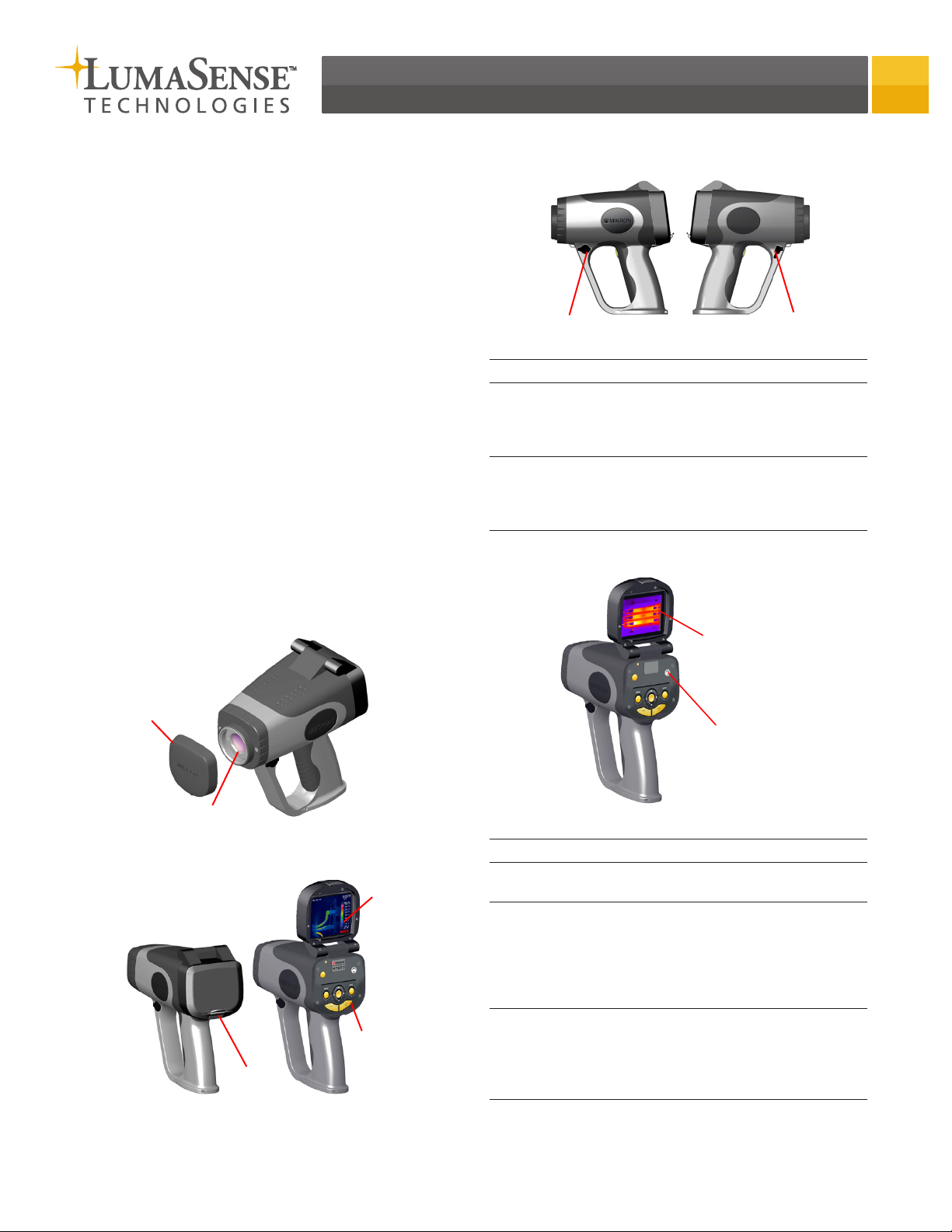
Button Control Functions
[1] Power Button
[2] Menu
Button
[5] Save Button
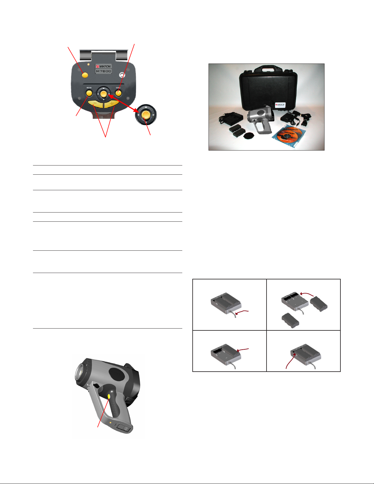
Unpacking and Inspection
The M7815 thermal imaging camera is shipped in a
rugged and padded carrying case along with two battery
packs, a battery charger, AC Adapter and AC power cable,
USB cable, lens cap, software and operating manual.
No. Description
1 Power Button
2 Menu Button
3 Focus Buttons
4 Joystick
Button
5 Save Button
6 Trigger
Button
[3] Focus
Buttons
Function
Used to turn the power on and
off.
Used to access the menu system
and to cancel out of certain menu
functions.
Used to focus in and focus out.
Used to navigate through the
main menu functions and to gain
access to the quick menu functions.
Saves the current image data
in either the “run” or “freeze”
modes.
Used to activate the target laser.
Also used to freeze an image and
return to the run mode. It can
also be configured to serve as an
alternate save button. As such, it
would automatically freeze the
image, save the image and then
return to the run mode.
[4] Joystick
Button
When unpacking and inspecting the camera, you
need to do the following:
1) Check container contents against the shipping list.
2) Carefully unpack and inspect all components for visible damage.
3) Save all packing materials, including the carrier’s
identification codes, until all components are
inspected and no obvious or hidden damages were
found.
Before shipment, the camera was assembled, calibrated, and tested at the LumaSense Factory. If any
damage or suspect damage is noted, immediately
contact the carrier and LumaSense.
Charging the Batteries
Step 1 Step 2
[6] Trigger Button
Step 3 Step 4
1) Plug the battery charger power cord into a standard
wall outlet.
2) Position one battery pack on the battery charger by
aligning the brackets and terminal ports on the battery pack to those on the charger.
3) Press down on the battery pack while sliding it forward into position.
4) Repeat steps 2 and 3 for the second battery pack.
Page 3

Inserting the Battery
Battery Door
1) Open the battery door located on the bottom of
the camera handle.
2) Place the fully-charged battery pack into the
battery compartment of the camera.
3) Push the battery forward into position.
4) Close the battery door.
Obtaining the First Image
1) Connect the power supply or insert the battery.
2) Open the LCD display/interface hatch cover on the
back of the camera.
3) Press and hold the power button for more than 1
second to turn the camera on.
Power Button
Attaching the AC Adapter
Step 1
AC Adapter
Terminal
1) Open the AC Adapter terminal cover on the camera.
2) Connect the DC connector of the AC Adapter to the
DC input connector on the camera.
3) Plug the AC power cord into a standard wall outlet.
IMPORTANT
•TheACAdapterprovidespowertothecamerabut
does not charge the battery.
Step 2 Step 3
DC Connector
AC Connector
Removing and Replacing the Lens Cap
The camera will then enter an initialization mode.
The display will appear showing the software version, the color palette bar, and the progress of the
system check in the form of a blue dashed line.
Camera Software Version
System
Check
Initialization in Progress
The camera will then enter the run mode and the
display will change to show additional information
on the various camera settings.
4) Remove the lens cap.
5) Tilt the LCD display as needed to adjust for proper
viewing.
6) Aim the camera at a recognizable warm object like a
hand or cup of coffee.
Date/Time
Palette Bar
Run/Freeze Mode
Lens Cap
Removing the Lens Cap
1) Squeeze the lens cap on both sides.
2) Pull the lens cap off of the camera optics.
Replacing the Lens Cap
1) Position the lens cap over the camera optics.
2) Press the lens cap onto the camera.
Image
Display
Temperature
Range
Color
Palette
Bar
Main Display-Run Mode
The color contours shown in the display delineate
areas of different temperature, and the actual
temperature of a given area can be established by
comparing the color of the area with the color palette bar and the equivalent temperature scale (See
figure above).
Page 4

Accessing the Quick Menu Functions
The M7815 offers quick access to a number of features
using the joystick.
The quick menu functions are as follows:
Feature Function
Range
Average Signal to Noise improvement (Off, ∑2,
Color Allows you to switch between a color
Page Allows you to scroll through images
JOYSTICK BUTTON AND FUNCTIONALITY
1) Press the JOYSTICK button to gain access to the
M7815 quick menu functions.
The M7815 provides a total of two
temperature ranges. These two ranges
provide an overall temperature span of
-20°C to 500°C (-4°F to 932°F).
∑8, ∑16)
display and a monochrome display.
that have been saved to the camera’s
internal memory
[QUICK MENU OPTION HIGHLIGHTED]
[PALETTE BAR HIGHLIGHTED]
3) Toggle the JOYSTICK up or down to switch between
the color display and the monochrome display.
The M7815 also allows one to choose black and
white as the preferred color palette for focusing.
Refer to the operator’s manual for more information on setting the focus mode option.
Toggling between Run and Freeze Modes
The M7815 on board processing software allows images
to be viewed at a rate of 60 frames per second in the
run mode. Because the run mode operates in real-time,
the time clock, image, and image data are continuously
updated.
The software also allows the image to be frozen, stopping the time clock and allowing more time for viewing
and analyzing data associated with a single image frame.
2) Press the JOYSTICK again until the desired quick
menu option becomes highlighted on the display.
3) Toggle the JOYSTICK up or down as needed to scroll
through the values and select the desired value.
4) Press the MENU button to return to the main display.
Switching Between the Color and Monochrome Display
The instrument has the capability of switching back and
forth between a color and monochrome display.
1) Press the JOYSTICK button to gain access to the
M7815 quick menu functions.
2) Press the JOYSTICK button again until the palette bar
becomes highlighted.
Trigger Button
1) Verify FREEZE has been selected as the
TRIGGER button option in the INITIAL Setup Menu.
2) Press and release the TRIGGER button to place the
camera into [FREEZE] Mode.
3) Press and release the TRIGGER button againe to
return the camera to [RUN] Mode.
Adjusting the Focus
1) Verify the display is in [RUN] mode and that no other
parameter is highlighted.
2) Press the FOCUS (-) or FOCUS (+) buttons as needed to
display the focus indicator bar and focus the camera.
Focus Button (-)
Focus Button (+)
Page 5
Pressing the FOCUS (+) button will move the blue
focus indicator bar toward the far focus range of
infinity.
Pressing the
focus indicator bar toward the near focus range of
30 cm.
FOCUS (-) button will move the blue
[FOCUS INDICATOR BAR]
[NEAR]
[FAR]
Accessing the M7815 Main Menu Functions
To access the main menu of the M7815:
1) Press the MENU button to gain access to the M7815
expanded menu.
[MENU CATEGORY HIGHLIGHTED]
2) Toggle the JOYSTICK to the left or right as needed
until the desired menu category appears with its pulldown menu.
3) Toggle the JOYSTICK up or down as needed to high-
light the desired main-menu choice.
4) Press the JOYSTICK button to select the menu option.
OR press the
menu mode and to return to the main display.
MENU button to cancel out of the
Using the Manual Power Standby Mode
The M7815 provides a manual power standby feature
which is used to conserve battery power and to
eliminate detector stabilization time when making intermittent measurements.
1) Close the LCD cover to place the camera in Standby
Mode.
The instrument will enter standby mode and will
remain in standby mode until the LCD cover is once
again opened.
IMPORTANT
•ThePowerStandbyfeaturedoesnotshutthecamera
down. It only places the camera in standby mode.
•DonotleavethecamerainStandbyModeforan
extended period of time as it will eventually
deplete the battery charge.
•Besuretoturnthecameraoffwhenthemeasurements have been completed.
Saving Images
The M7815 on board processing software allows you to
store images to the internal memory utilizing the M7815
.SIT file extension.
These images are saved in a full 14-bit digital format and
includes all the data associated with the file.
1) Aim the camera at a specific target of interest.
2) Make any desired adjustments to the temperature
range setting or temperature level and sensitivity.
3) Focus the camera.
4) Press the TRIGGER button to freeze the image and
then press the save button to save the image.
Once the save button has been pressed, the display will flash the visible image and then save the
desired image(s) to the camera’s internal memory.
The image file can then be viewed on the camera or
downloaded to a PC through the USB port.
Or, if the
to work as a save button
5) Press and hold the TRIGGER button while aiming the
6) Release the trigger button to save the image.
TRIGGER button had previously been configured
camera at the desired target.
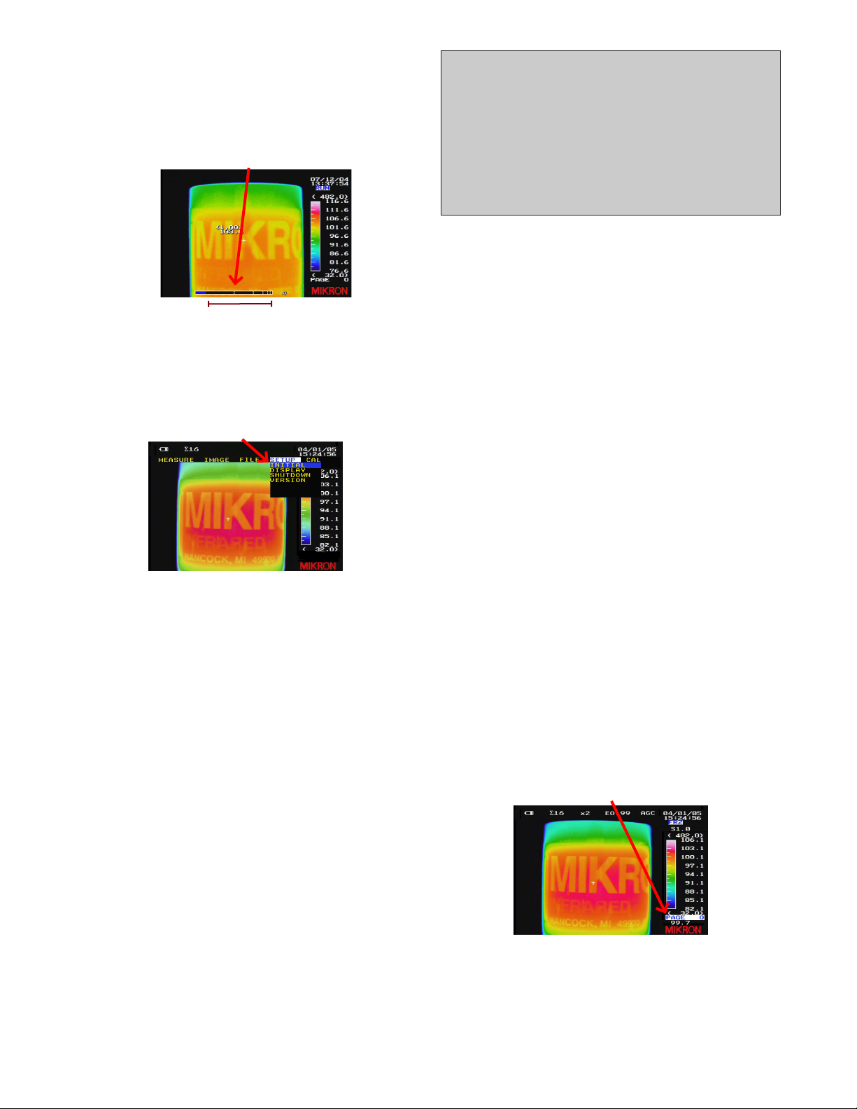
Reviewing Images Using the Page Feature
1) Press the JOYSTICK button to gain access to the
M7815 quick menu functions.
2) Press the JOYSTICK button again until the PAGE quick
menu option becomes highlighted on the display.
Once the page option has been selected, the
camera will automatically enter freeze mode and
will allow one to scroll through the images.
[PAGE NUMBER HIGHLIGHTED]
2) Open the LCD cover to return to normal operation.
The instrument will go through the system check
and normal operation will resume after approximately 20 seconds.
3) Toggle the JOYSTICK left or right as needed to scroll
through the pages of stored images.
4) Press the TRIGGER button to return to [RUN] mode.
Page 6

Downloading Images
The M7815 software allows you to download images and
image data from the camera to an external device using
the USB-2 port.
Connecting to a Windows PC
1) Verify that you have power supplied to the M7815
camera via batteries and/or the AC Adapter.
2) Connect the USB connector to the USB input connector on the camera.
USB Port
3) Power on your computer and verify that your Windows XP operating system is running.
4) Power on the M7815 camera.
5) Connect the USB cable to the USB 2.0 port on your
personal computer.
Make sure that you power on your computer and
that Windows is booted up BEFORE making this
connection.
Installing the Driver (first time use only)
1) Insert the M7815 software CD-ROM into the CD-ROM
drive on your computer.
The software CD-ROM contains the appropriate USB
driver which is used by the plug-and-play feature of
the Windows Operating System’s Add New Hardware
Wizard.
Once the driver has been installed, it remains on your
system’s hard drive and, therefore, does not need to
be reinstalled each time you use the software. It also
does not need to be reinstalled each time you install
or reinstall any version of the M7815 software.
2) Complete the steps provided by the Add New Hardware Wizard.
3) When completed, click the [FINISH] button on the
Found New Hardware Screen.
Installing the Software (first time use only)
1) Verify that the M7815 software CD-ROM has been
inserted into the CD-ROM drive on your computer.
The software CD-ROM contains an auto-run feature
that will allow you to step through the installation
process.
2) If needed, check the software version that you wish
to install and then click the [INSTALL] button to proceed.
3) Complete the steps provided by the M7815 Setup
Wizard
4) When completed, remove the software CD-ROM from
your CD-ROM drive.
Downloading Images to your PC
1) Verify that the M7815 camera is turned on and that
the USB-2 connection has been made to your computer.
2) Click on the M7815 Application located in the
Application folder within the Windows™ Operating
System Start menu.
Once the program has been started, you will be pre-
sented with the M7815 start screen.
3) Select [DOWNLOADER] from the list of options under
the [FILE] menu.
4) Click on the [DOWNLOAD ALL] or [DOWNLOAD
SELECTED] button located at the bottom of the
M7815 Downloader Screen.
Once the images have downloaded, the M7815
Downloader Screen will reappear with a [DOWNLOAD
COMPLETE MESSAGE].
5) Click on the [CLOSE] button to close the M7815
Downloader Screen and to return to the M7815 start
screen.
LumaSense Technologies Temperature and Gas Sensing Solutions
Americas and Australia
Sales & Service
Santa Clara, CA
Ph: +1 800 631 0176
Fax: +1 408 727 1677
info@lumasenseinc.com
LumaSense Technologies, Inc., reserves the right to change
the information in this publication at any time.
Europe, Middle East, Africa
Sales & Service
Frankfurt, Germany
Ph: +49 69 97373 0
Fax: +49 69 97373 167
India
Sales & Support Center
Mumbai, India
Ph: +91 22 67419203
Fax: +91 22 67419201
China
Sales & Support Center
Shanghai, China
Ph: +86 133 1182 7766
Fax: +86 21 5039 8096
www.lumasenseinc.com
©2011 LumaSense Technologies. All rights reserved.
Part No. 578-0006-01 Rev. A July 2011
 Loading...