

BoilerSpection-IM Quick Start Guide
Introduction
BoilerSpection-IM is a mobile infrared camera system
used by operators to survey the furnace to identify tube
leaks, guide cleaning actions, and monitor/tune the
overall combustion process. The User Manual includes
complete operation details while this Quick Start Guide
provides instruction to begin basic operation and record
images of your furnace/boiler in a matter of minutes.
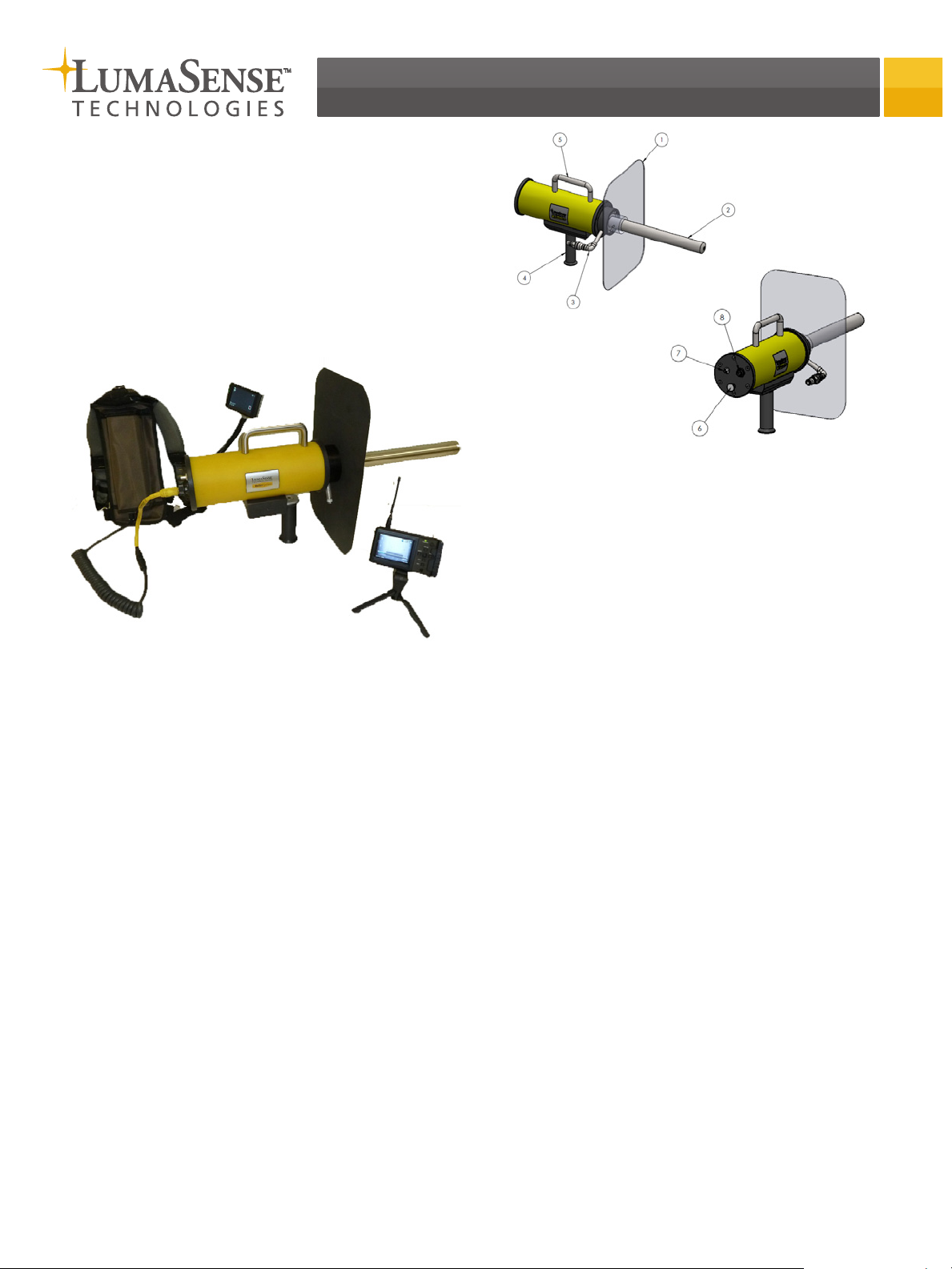
System Features
Base System
1. Adjustable
radiation shield
2. Interchangeable
lens
3. Air fittings for lens
cooling/purge
4. Removable handle
5. Top handle
6. Focus knob
7. BNC video output
8. 12VDC power input
Using the Main Battery
Backpack
The main battery backpack is used to power the infrared
camera and the video transmitter inside of the camera
enclosure for up 20 hours. The backpack is intended to
give you the freedom to inspect numerous ports throughout the plant.
The base system includes:
• Uncooled microbolometer infrared camera (320 x
240 resolution)
• Choice of lens with integral cooling and purge
• Protective camera enclosure
• Adjustable radiation shield
• Local display with DVR capture to micro-SD
memory card
• Battery backpack and charger
• Storage Case
Options
• Wireless display with DVR capture to SD memory
card
• Interchangeable optics with different angles and
field of views
• Air filtration system and air hoses for continuous
operation in a furnace
• Travel case
• On-site service and training
Charging the Battery
Align the connector on the flex cord to the connector
on the charger. A red light will turn on during charging.
After charging is complete and the green LED turns on,
disconnect the cord from the charger. Take care to align
the black flex cord connector to the connector on the
battery backpack.
Connecting the Main Battery to the
Camera
1. Put the backpack on your shoulders.
2. Connect the yellow connector on the flex cord to
the mating connector on the back of the camera
enclosure.
Once you connect the yellow connector, the camera
and wireless transmitter will automatically power
on.
Installing or Exchanging the
Borescope Lens
BoilerSpection-IM supports interchangeable lens. Users
can purchase additional lens depending on the intended
use of the camera system.
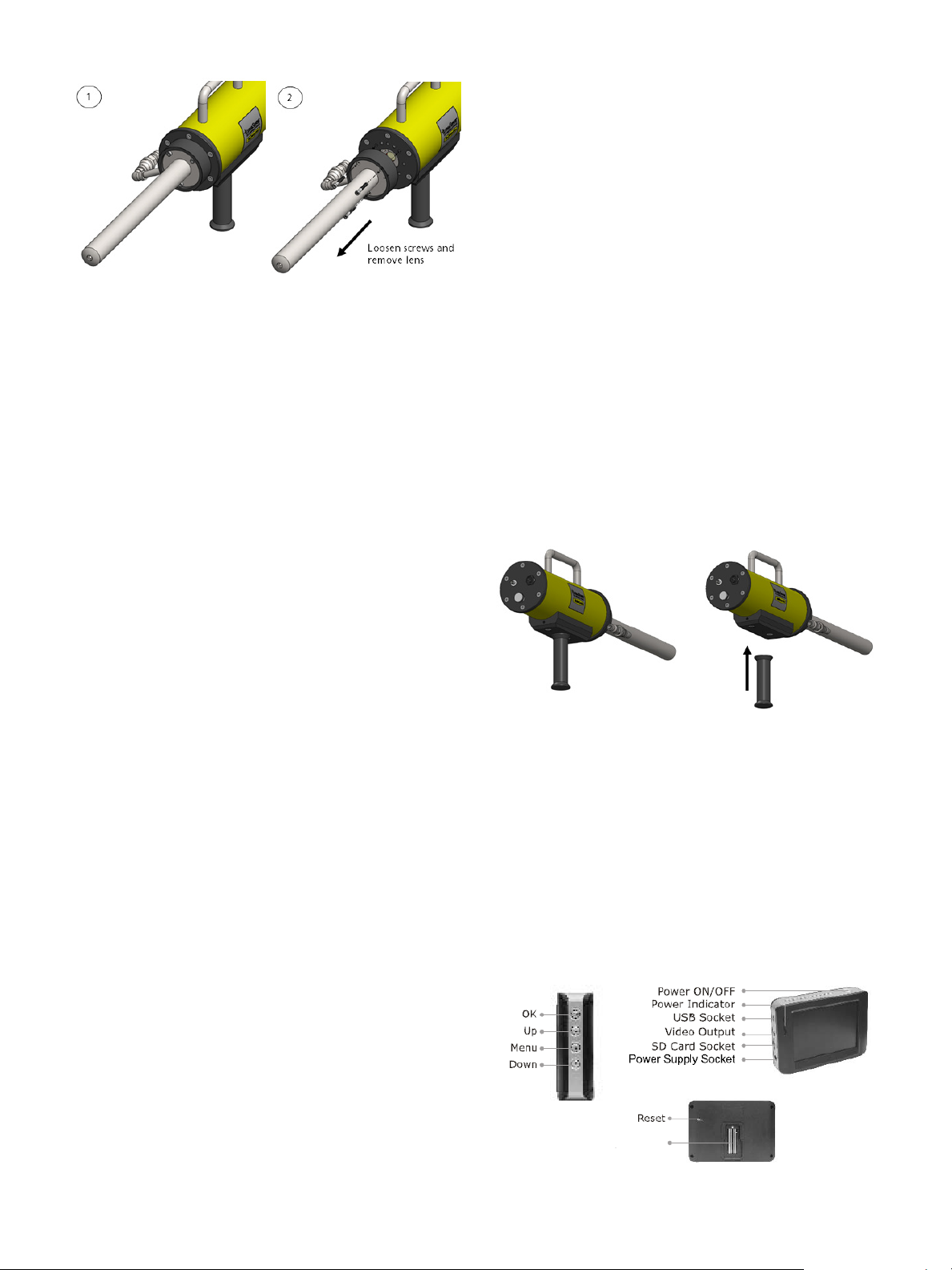
The lens shroud is attached to the front plate of the
enclosure by three ¼-20 socket head cap screws. The lens
tube is attached to the lens shroud and does not need
separate removal.
1. Turn the ¼-20 socket head cap screws counter clockwise to remove them from the front plate. The lens
shroud, lens tube, and air fittings come off as one
piece.
2. Align second lens with the threaded holes and
insert the three ¼-20 socket head cap screws. Turn
them clockwise to tighten.
Before storing the camera lens and radiation shield in
the storage case make sure that all the equipment have
cooled to less than 50 °C (120 °F) to prevent melting the
case foam.
Connecting the Air Filters and
Hoses (Optional)
Connect air to the camera system if you intend to leave
the camera inserted into the furnace for longer term
measurements or continuous monitoring. LumaSense
offers an optional air filter and hose kit for use with the
BoilerSpection-IM camera. The kit incorporates a quickconnect fitting to attach the air hose to the inlet on the
BoilerSpection camera. Drawings of this kit are provided
in Chapter 7 of manual.
The system includes a Chicago type fitting to connect to
the plant instrument air supply.
Installing the Handle
If your system was ordered in a storage case, the handle
will be installed. If your system was ordered in a travel
case, then the handle needs to be screwed clockwise into
the base of the camera. To remove the handle, turn it
counter-clockwise.
Installing the Radiation Heat
Shield
The radiation shield can be secured at a variable distance
from the camera enclosure depending on the application
and the lens being used. The adjustable radiation shield
can be used as a stop so that the lens is not inserted
beyond the refractory and have the lens in the port
longer. Setting the radiation shield insertion depth is also
used to help protect the user from flying debris and positive pressure.
Installing the Radiation Heat Shield
1. Slide the radiation shield over the lens shroud. The
collar on the radiation shield should face the yellow
camera housing.
2. Secure the radiation shield in place using the (3)
thumb screws.
Caution: Proper clothing, gloves, and eye protection
should be worn when inserting the camera into a port
per plant safety regulations.
Removing the Radiation Heat Shield
1. Loosen the three (3) thumb screws.
2. Slide the heat shield away from the yellow camera
housing along the lens shroud.
Warning: Utilize extreme caution when removing the
radiation shield because the lens shroud and radiation
shield can be extremely hot. It is recommended that
you let the temperature of the lens and radiation shield
naturally cool to 50 °C (120 °F) before disassembly. This
is required for user protection and for the high temperature optics. The optics need to cool by natural convection
to preserve their integrity.
Caution: Gloves should be worn when holding the
camera in a furnace per the local plant’s safety regulations.
Using the Onboard Display
An onboard display is attached to a flexible arm allowing
you to adjust the position of the display during use. The
display has an integrated digital video recording (DVR) to
save images and video to a micro-SD memory card. The
flexible arm allows the display to be positioned to either
the left side or the right side of the camera for the user’s
convenience.
Components
Mount

Powering On the Display
1. Press and hold the Power ON/OFF button for 2 seconds. The power indicator will turn green.
2. Press the button to select CH4 to display picture
on the LCD screen.
Recording Video
1. During operation, press to enter Video mode.
4. To pause, press OK when the video is playing. Press
again to resume.
5. Press to fast forward during playing status.
6. Press to rewind during playing status.
7. Press to stop or exit.
8. For Photos, press or to select picture, then
press OK to display. Press OK again to exit.
Delete Video or Photo
1. During operation, press to display the playback
screen (shown above).
2. Press or to select folder, then press OK to
select.
3. Press or to select file, then press and hold
for 2 seconds.
2. Press the OK button to start recording.
3. Press the OK button again to stop recording.
Capturing Photos
1. During operation, press to enter Photo mode.
2. Press the OK button to capture photo.
Playback Video or Photo
1. During operation, press to display:
2. Press or to select folder, then press OK to
select.
3. For Videos, press or to select folder, then
press OK to play.
4. Press or to select YES, then press OK to
delete file.
OR
If you do not want to delete the selected file, select
NO and press OK to exit.
Transferring Recorded Images and
Videos to a PC
Both the standard onboard display and the optional
wireless display record images to memory cards. These
memory cards can be removed from the display and
inserted into PCs for transfer. The wireless display also
includes a USB cable that you can connect the display
directly to a PC for transfer.
Using the Hand Held Display
(Optional)
The display receives the same image from the camera,
simultaneously, as that received by the onboard display.
The user can also record snapshots and videos to the
display’s SD memory card.
Note: The camera wirelessly transmits the video signal on
Channel 4. If you have problems receiving an image, refer
to the troubleshooting section of the manual.
Inserting the Battery
1. Remove the battery compartment cover in the back
of the hand held display.
2. Align the gold contacts of the supplied battery with
corresponding connectors on the hand held display.
3. Slide the battery in until it fits into place.

Charging the Battery
Before using the hand held display, the battery must
be charged for at least 4 hours. However, the display
provided by LumaSense is already fully charged and can
be used as is.
1. Plug the supplied DC 5V power adapter to an AC
wall outlet and then connect the other end of the
power cord to the DC IN socket on the side of the
display. The red Charge indicator LED will illuminate
while the battery is charging.
2. Once the red Charge indicator LED has turned off,
connect the display from the DC 5V power adapter.
The display is now fully charged and ready to use.
Setting up the Receiver
Refer to the manual for a detailed diagram.
1. To receive the same video output, the channel
should be set at CH4. This channel is set as the
default channel.
2. If the need arises to change the channel, remove
the Channel Select Pen and lift up the appropriate
dip switch channel selectors located on the opposite
side of the receiver.
3. To turn on the receiver, slide the selection bar on
the side of the receiver to “Receiver”.
4. To set the correct frequency, slide the selection bar
to 2 for 2.4 GHz. Attach the antenna to the mount
labeled 2 as well.
Operating the Display
Set Video Storage Options
1. With the unit on, navigate to the main menu.
2. Scroll down and select Settings. Scroll to Page 3 of 7
and select Storage Options.
3. Select the preferred option: HDD or SD.
Record Video
1. With the unit and receiver turned on and channel set correctly, press the Record button to start
recording.
2. Press the Stop button on the front panel of the unit
to stop recording.
Capture Images
1. While recording, press the Photo button on the
front panel of the unit to capture a still image of
the scene.
The captured image will be stored in the same storage location as determined by the user.
Using the Auxillary BNC Video
Output Connector
The back panel of the camera has a BNC video output
connector that allows you to connect any standard video
accessory to receive live images from the system.
Adjusting the Focus
The focus knob is found on the back panel of the camera.
While viewing a hot source, turn the knob while looking
at the video display until the image is sharp. Expect to
re-adjust focus after changing the lens.
For complete instruction, view the user manual located
on the enclosed CD.
LumaSense Technologies Temperature and Gas Sensing Solutions
LumaSense Technologies Temperature and Gas Sensing Solutions
Americas and Australia
Sales & Service
Santa Clara, CA
Ph: +1 800 631 0176
Fax: +1 408 727 1677
info@lumasenseinc.com
the information in this publication at any time.
Europe, Middle East, Africa
Sales & Service
Frankfurt, Germany
Ph: +49 69 97373 0
Fax: +49 69 97373 167
India
Sales & Support Center
Mumbai, India
Ph: +91 22 67419203
Fax: +91 22 67419201
BoilerSpection-IM Quickstart-EN 512-0005-01 Rev. A 11/07/12
China
Sales & Support Center
Shanghai, China
Ph: +86 133 1182 7766
Fax: +86 21 5877 2383
www.lumasenseinc.com
©2012 LumaSense Technologies. All rights reserved.LumaSense Technologies, Inc., reserves the right to change
 Loading...