

Page 1
Technical data
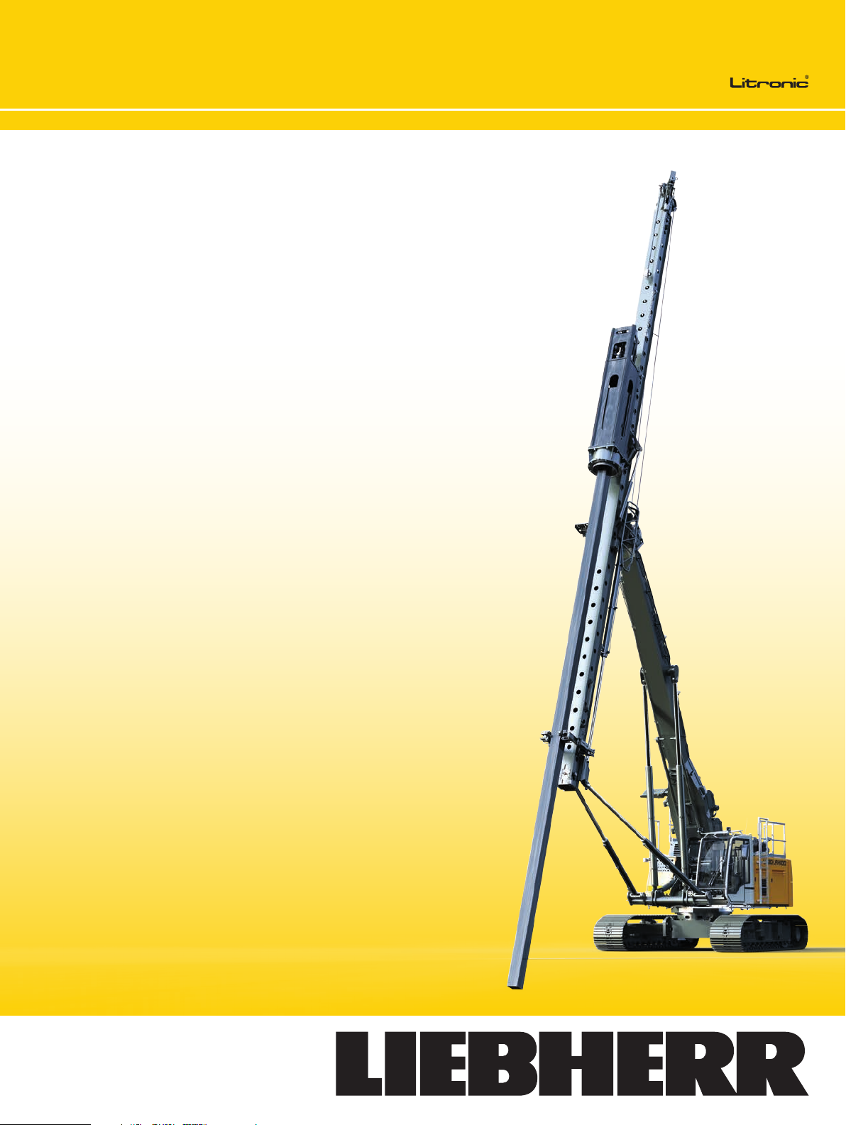
Piling rig
LRH 100
Page 2
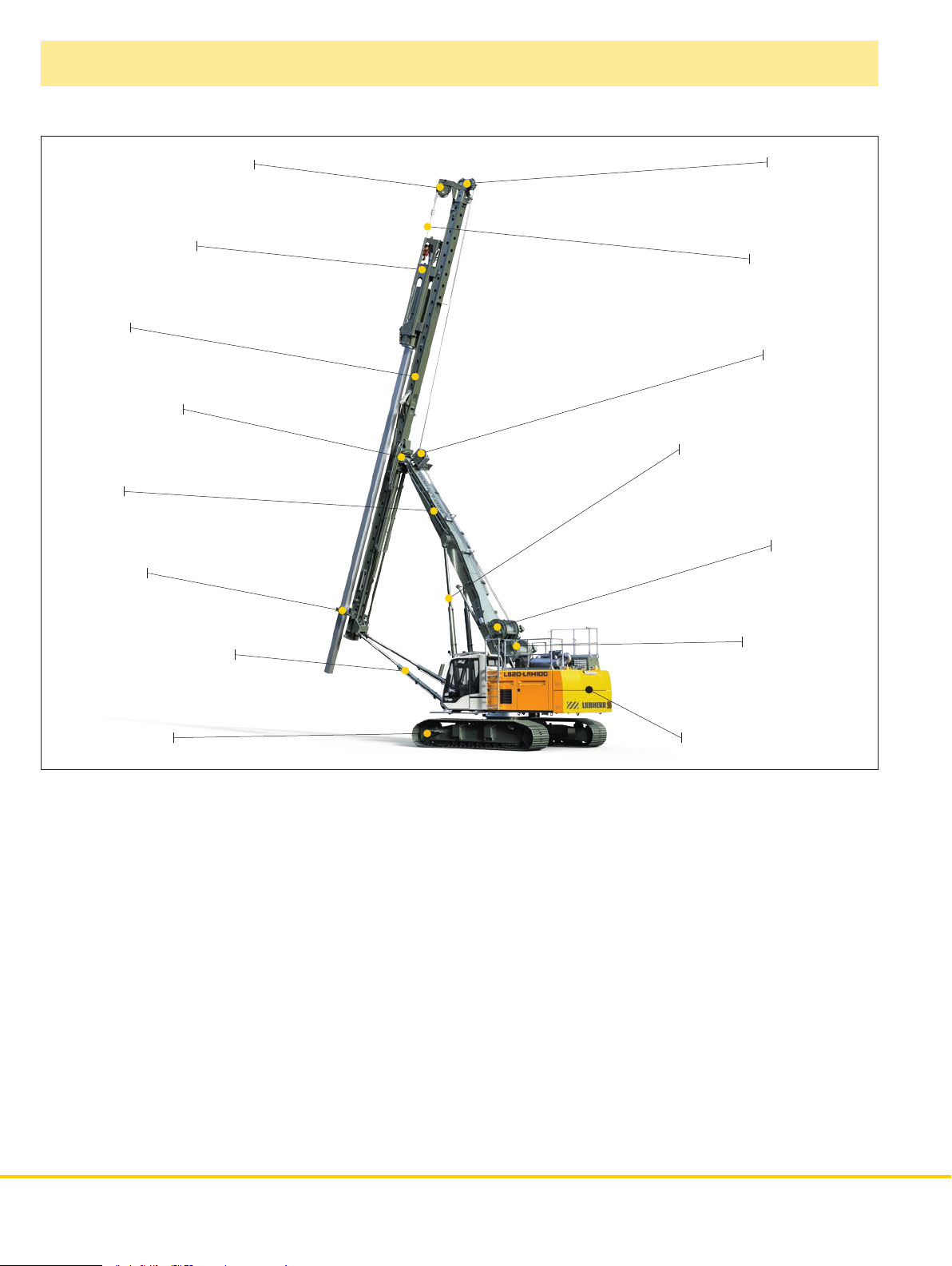
Concept and characteristics
Leader top for auxiliary rope
Hydraulic hammer
Leader
Leader ball joint
Boom
Pile guide
Leader top
Auxiliary rope
Rope guide
Radius adjustment device
Pile winch
Leader inclination device
Undercarriage
• The LRH 100 is based on the well-proven
LB 20 basic machine
• Thanks to the special leader kinematics a radius of 28.7 ft
as well as a continuous inclination adjustment of 1:3 in all
directions is achieved
• The flexible hammer design offers the possibility of
mounting drop weights between 5,512 lbs and 15,435 lbs.
This guarantees optimum adaptation to the required
pile type
• A new joystick design allows for leader movements to be
carried out at all times and simultaneously to other machine
movements
• Automatic vertical leader alignment at the push
of a button
• Automatic parallel adjustment in both axes
Hammer winch
Counterweight 26,455 lbs
• Automatic slack rope prevention
• Automatic slack rope preventionTransport fully assembled
with or without mounted hammer
• Completely self-rigging (no auxiliary machines required)
• Simultaneous control of several movements via Load-sen-
sing multi-circuit hydraulics
• Small rear swing radius
• Equipment design according to latest European regulations
and standards
• High manufacturing quality through quality control by PDE®
system
• Evaluation and visualisation using the new Liebherr process
data report software (PDR)
2 LRH 100
Page 3
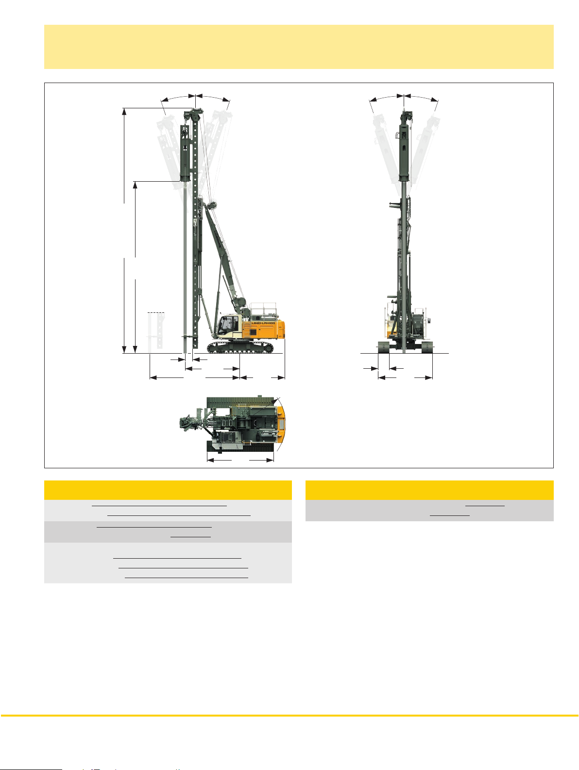
Dimensions
Basic machine LRH 100
65.6´- 82.1´
62.3´
18.4°
28´8´´
18.4°
23.6´´
14´9´´
12´1´´
18.4°
18.4°
35.4´´
14´5´´
17´11´´
Technical data
Total height 65.6 - 82.1 ft
Max. pile length 62.3 ft
Drop weight* 5,515 - 15,435 lbs
Hammer weight incl. drop weight* 12,350 - 22,930 lbs
Leader inclination continuously variable
Lateral inclination ± 18.4°
Forward inclination 18.4°
Backward inclination 18.4°
*) See table on page 6
R 12´4´´
Operating weight
Total weight with 35.4 inch 3–web grousers 14 3,3 0 0 lb s
Weight of hydraulic hammer H 40 see table on page 6
The operating weight includes the basic machine (hydraulic hammer
H 40/2.5 with 12,350 lbs dead weight) and 26,500 lbs counterweight.
LRH 100 3
Page 4
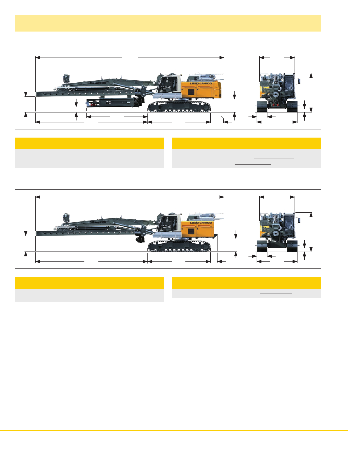
Transport dimensions and weights
52´8´´
55.1´´
16.9´´
17´ 7´´
Transport - with hydraulic hammer
includes the basic machine (ready for operation) with
leader, hydraulic hammer type H 40 and counterweight.
52´8´´
9´10´´
11´2´´
12.2´´
44.1´´
35.4´´
17´11´´31´9´´
36.2´´
11´5´´
Weights
Weight complete with
hydraulic hammer and counterweight 143 ,300 lbs
Weight of hydraulic hammer see table on page 6
The operating weight includes the basic machine (hydraulic hammer
H 40/2.5 with 12,350 lbs dead weight) and 26,500 lbs counterweight.
9´10´´
55.1´´
Transport - standard
includes the basic machine (ready for operation) with
leader without working tools and counterweight.
Weights can vary with the final configuration of the machine.
12.2´´
44 .1´´
17´11´´31´9´´
23.2´´
25.4´´
11´5´´
Weights
Weight complete without counterweight 104,720 lbs
11´2´´
4 LRH 100
Page 5

Transport dimensions and weights
19´10´´
44.1´´
17´11´´
Transport basic machine
ready for operation, without counterweight.
Transport weight
5´6´´
69,450 lbs
5´6´´
41´8´´
9´10´´
7´
18.9´´
9´10´´
35.4´´
11´5´´
41´8´´
12.2´´
11´2´´
9´10´´
30.5´´
Counterweight
Counterweight
13,230 lbs + 13,230 lbs
5´4´´
43.7´´
Hammer
Transport weight
H 40/2.5 12,350 lbs
9´10´´
15´11´´
43.9´´
7´
Transport leader
includes the leader without working tools (hydraulic hammer,
pre-drill etc.).
The figures include options which are not within the standard scope
of supply of the rig.
Weights can vary with the final configuration of the machine.
18.9´´
Weights
Weight complete 35,280 lbs
LRH 100 5
Page 6

Hydraulic hammer
12:11
2
1
2
1
MODE
700
1000
1300
1600
1900
2200
rpm
0
20
40
60
80
100
Nm%
0
20
40
60
80
100
0
20
40
60
80
100
HG 1 HG 2
2.4
kN
0.2
kN
-12.12 m
0.04
m/min
0
100
200
300
400
bar
0100200300400
bar
/min
61
mm
25
kNm
515
0.0 °
°-0.2
0.2 °
Type H 40
Pile with pile guide
Technical data H 40
Hammer type H 40/2.5 H 40/4 H 40/5 H 40/7*
Drop weight 5,515 lbs 8,820 lbs 11,025 lbs 15,450 lbs
Max. rated energy 14755 l bf-ft 22130 lbf-ft 29500 lbf-ft 40565 lbf-ft
Blow rate -
blows/min
Hammer weight
incl. drop weight
*) Only in combination with extension hammer cage
Various drive cap sizes between 15.7 inch and 27.6 inch diameter
available on request.
6 LRH 100
55-80 50-80 50-80 40-80
12,350 lbs 15,56 0 lbs 17,860 lbs 22,930 lbs
Display for hydraulic hammer
Page 7

Pre-drill*
T ype BA12
Auger with auger guide
Technical data
Rotary drive - torque 0 – 8,850 lbf-ft
Rotary drive - speed 0 – 65 rpm
Max. drilling diameter 0 – 13.8 inch
Other drilling diameters available on request.
*Only for machines with hammer H 40/2.5, H 40/4 or H 40/5
LRH 100 7
Page 8

Technical data
Engine
Power rating according to ISO 9249, 270 kW (362 hp) at 2000 rpm
Engine type
Fuel tank
indicator and reserve warning
Engine complies with NRMM exhaust certification EPA/CARB Tier 4i
or 97/68 EC Stage III B.
Liebherr D 936 A7 SCR
185 gal capacity with continuous level
Hydraulic system
The main pumps are operated by a distributor gearbox. A xial piston
displacement pumps work in open circuits supplying oil only when
needed (flow control on demand). The hydraulic pressure peaks are
absorbed by the integrated automatic pressure compensation, which
relieves the pump and saves fuel.
Pumps for working tools 2x 63 gal/min
Separate pump for kinematics 36 gal/min
Hydraulic oil tank 159 gal
Max. working pressure 5076 PSI
The cleaning of the hydraulic oils occurs via an electronically monitored
pressure and return filter. Any clogging is shown on the monitor in the
cab. The use of synthetic environmentally friendly oil is also possible.
Control
The control system - developed and manufactured by Liebherr - is
designed to withstand extreme temperatures and the many heav yduty construction tasks for which this machine has been designed.
Complete machine operating data are displayed on a high resolution
monitor. A GSM/GPRS/GPS-modem allows for remote inquiry of
machine data and error indications. To ensure clarity of the information
on display, different levels of data are shown in enlarged lettering and
symbols.
Control and monitoring of the sensors are also handled by this high
technology system. Error indications are automatically displayed
on the monitor in clear text. The machine is equipped with electrohydraulic continuous proportional control for all movements, which can
be carried out simultaneously. Two joysticks are required for operation.
Pedal control can be changed to hand control.
Options:
• PDE:processdatarecording
• GSM/GPRS/GPS-modem
Hammer winch with free fall
Line pull (effective) 23,380 lbf
Rope diameter 24 mm
Rope speed 0 -18 0 f t /min
The winches are noted for compact, easily mounted design.
Propulsion is via a maintenance-free planetar y gearbox in oil bath.
Load support by the hydraulic system; additional safety factor by a
spring-loaded, multi-disc holding brake.
Crawlers
Propulsion through axial piston motor, hydraulically released spring
loaded multi-disc brake, maintenance-free crawler tracks, hydraulic
chain tensioning device.
Drive speed of telescopic undercarriage 0 – 1.1 mph
Track force 103,415 lbf
Width of 3–web–grousers 35.4 inch
Transport width 11´5 ´ ´
Swing
Swing ring with triple row roller bearing, external teeth and one swing
drive, fixed axial piston hydraulic motor, spring loaded and hydraulically
released multi-disc holding brake, planetar y gearbox and pinion.
Selector for 3 speed ranges to increase swing precision.
Swing speed from 0 – 3.5 rpm is continuously variable.
Pile winch with free fall
Line pull (effective) 17,9 8 5 l b f
Rope diameter 20 mm
Rope speed 0 -18 0 f t /min
The winches are noted for compact, easily mounted design.
Propulsion is via a maintenance-free planetar y gearbox in oil bath.
Load support by the hydraulic system; additional safety factor by a
spring-loaded, multi-disc holding brake.
Noise emission
Noise emissions correspond with 2000/14/EC directive on noise
emission by equipment used outdoors.
8 LRH 100
Page 9

Process data recording system - PDE
hammer
®
(additional equipment)
The Liebherr process data recording system PDE® constantly records the relevant process data
during the working process.
66%
pile number Liebherr 123
13
14
8
7
8
0 5 10 15
7
0 5 10 15
10mm/10
ABC
®
PDE
colour monitor for visualization of the
®
data in the operator's cab
PDE
11.9 m
12.0 m
12.1 m
12.17 m
93
/100 mm
0 20 40 60 80 100
0 20 40 60 80 100
82
CompactFlash
memory card
®
Printer
PDE
Standard
Optional
PC provided
by the customer
Depending on the application the recorded and processed data are displayed on the PDE
Process data report
software
PDR
External sensors
®
touchscreen in the operator‘s cab, e.g. in the form of
an online cast-in-place pile.
At the same time the PDE
start and stop recordings. A recording of every start-stop cycle carried out in the PDE
®
is operated using this touchscreen. The operator can enter various details (e.g. jobsite name, pile number, etc.) and
®
is established on a CompactFlash memory card.
The PDE® can be configured in a number of ways, e.g. for the connection of external sensors, for the generation of a simple protocol as graphic
file and/or for a printout directly in the operator‘s cab.
Process data reporting - PDR (additional equipment)
Comprehensive data evaluation and generation of reports on a PC is possible using the
software PDR.
Recordings management - The recordings generated by the PDE® system can be imported and mana-
ged in PDR. The data can be impor ted directly from the CompactFlash card or via the Liebherr telematics
system LiDAT. Certain recordings, e.g. for a particular day or jobsite, can be found using filter functions.
Viewing data - The data in each record is displayed tabularly. Combining several recordings provides
results, for example, regarding the total concrete consumption or the average depth. Furthermore, a diagram
editor is available for quick analysis.
Generating reports - A vital element of PDR is the report generator, which allows for the generation of
individual repor ts. These can be printed out directly or stored as pdf files. In the process the size, colour, line
thickness or even the desired logo can be configured. Moreover, the reports can be displayed in different
languages, e.g. in English and in the national language.
job site:
machine ID:
start date:
start time:
stop time:
duration:
depth [m]
<Naturum
1151xx
23.09.2009
16:45:12
17:19:56
00:34:44
blows/depth s tep v
16
17
18
19
20
21
22
energy/blow [ kNm] v
806040200
pile number:
maximum depth:
ram weight:
total energy:
total blows:
depth step:
151050
19
2200 cm
6000 kg
18774 kNm
6 0 5 1
10 cm
energy/depth s tep [kNm] v
1 0005000
LRH 100 9
Page 10

LRH 100 at work
10 LRH 100
Page 11

LRH 100 11
Page 12

Liebherr-Werk Nenzing GmbH
Dr. Hans Liebherr Str. 1, 6710 Nenzing/Austria
Tel.: +43 50809 41–473, Fax: +43 50809 41–499
crawler.crane@liebherr.com, www.liebherr.com
facebook.com/LiebherrConstruction
LRH 100 – 10538153 – 07/2014 Subject to change without notice.
 Loading...