

Page 1
Technical data
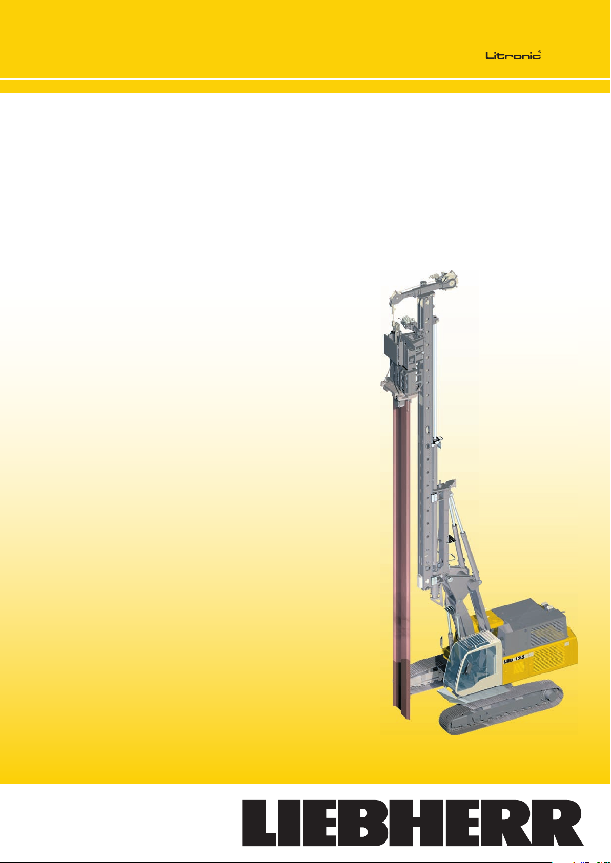
Piling and drilling rig
LRB 125 XL
Page 2
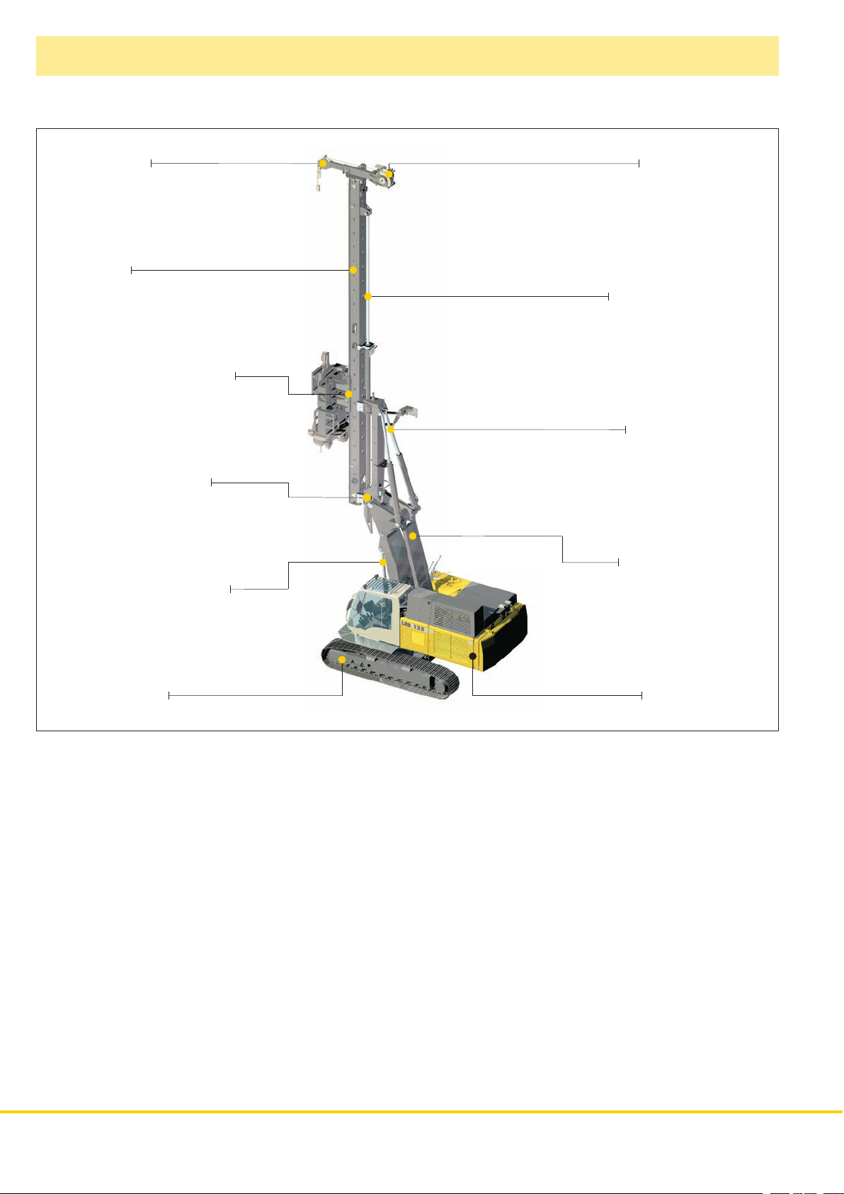
Concept and characteristics
Leader top
Leader
Tool with quick connection
Leader rotation device
Auxiliary winch
Vertical travel device
Inclination device
Parallel kinematics
Radius adjustment device
Undercarriage
• High engine output with automatic engine speed
control
• Controlled entirely from cab
• Sturdy and solid rig design
• Wide longitudinal and lateral supporting system on
the basic machine through triangles
• High push and pull forces
• High torque
• Completely self–rigging (no auxiliary machines
required)
• Large range of working tools (all piling and drilling
works can be performed)
• Stepless leader inclination 1:6 forward – 1:3 backward
depending on type of equipment
Uppercarriage
• Leader swing range ± 90º
• Increase of effective leader length (5 m) via vertical
travel device
• Automatic vertical alignment
• High alignment forces
• Simultaneous control of several movements via
Load–sensing multi–circuit hydraulics
• Quick change of equipment possible through quick
connection
• Equipment design according to latest European
regulations and standards
• High manufacturing quality through quality control by
PDE–system
2 LRB 125 XL
Page 3
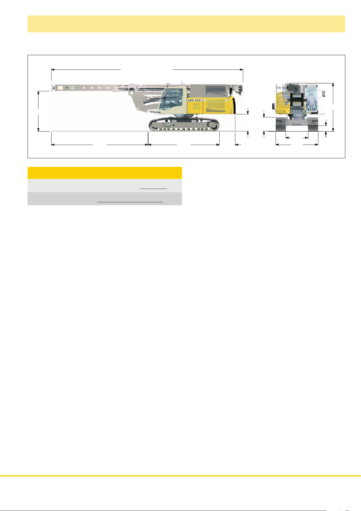
Transport dimensions and weights
1180
15850 incl. aux. winch
2850
7100 5100 1120
Transport weight*
Without attachment,
with telescopic undercarriage and counterweight 46 t
Without attachment and counterweight,
with telescopic undercarriage
*) Weights can vary with the nal con guration of the machine.
40.7 t
1180
1000
3400
400
1600
3000
LRB 125 XL 3
Page 4

Dimensions
Basic machine LRB 125
17500
1:6
1:3
2.8°
2.8°
3300
3150
5350
90°
90°
Technical data
Leader length 15 m
Capacity hammer including cap plus pile
Max. hammer weight 6 t
Max. pile weight 6 t
Max. pull 200 kN
Max. torque 120 kNm
Working radius machine
Center of rotation — center pile
Stepless rig inclination adjustment
Lateral inclination
Forward inclination 1:6
Backward inclination 1:3
Vertical leader adjustment above
ground level (depending on radius)
Leader swing range ± 90°
3.15 — 5.35 m
12 t
± 1:20
5 m
3670
700
4200
Operating weight and ground
pressure
Telescopic undercarriage with
700 mm 3–web shoes 52 t – 0.88 cm
The operating weight includes the basic machine LRB 125 (leader
length 15 m, with attachment). Weights can vary depending on the
nal con guration of the machine.
2
4 LRB 125 XL
Page 5

Technical description
Engine
Power rating according to ISO 9249, 450 kW (603 hp) at 1900 rpm
Engine type Liebherr D 9508 A7
Fuel tank 870 l capacity with continuous level
indicator and reserve warning
Engine complies with NRMM exhaust certication EPA/CARB Tier 3
and 97/68 EC Stage III.
Hydraulic system
The main pumps are operated by a distributor gearbox. A xial piston
displacement pumps work in open circuits supplying oil only when
needed (ow control on demand).
The hydraulic pressure peaks are absorbed by the integrated
automatic pressure compensation, which relieves the pump and
saves fuel.
Pumps for working tools 2x 350 l/min
Separate pumps for kinematics 2x 190 l/min
Hydraulic oil tank 825 l
Max. working pressure 350 bar
No auxiliary power packs are required as application specic
hydraulics supply power to all components.
The cleaning of the hydraulic oils occurs via an electronically
monitored pressure and return lter.
Any clogging is shown on the display in the cab.
The use of synthetic environmentally friendly oil is also possible.
Swing
Consists of single row ballbearing, xed axial piston hydraulic motor,
spring loaded and hydraulically released multi–disc holding brake,
planetary gearbox and pinion.
Swing speed from 0 – 3.3 rpm is continuously variable.
Control
The control system – developed and manufactured by Liebherr – is
designed to withstand extreme temperatures and the many heavy–
duty construction tasks for which this machine has been designed.
Complete machine operating data are displayed on a high resolution
monitor screen.
To ensure clarity of the information on display, different levels of data
are shown in enlarged lettering and symbols. Control and monitoring
of the sensors are also handled by this high technology system.
Error indications are automatically displayed on the monitor in clear
text.
The machine is equipped with proportional control for all movements,
which can be carried out simultaneously.
Two joysticks are required for operation. Pedal control can be
changed to hand control.
Options :
PDE : Process data recording
GSM modem
Crawlers
Propulsion through axial piston motor, hydraulically released spring
loaded multi–disc brake, maintenance free crawler tracks, hydraulic
chain tensioning device.
Drive speed 0 – 2.3 km/h
Track force 437 kN
Width of 3-web track shoes 700 mm
Noise emission
Noise emissions correspond with 2000/14/EC directive on noise
emission by equipment used outdoors.
Auxiliary winch
Line pull (effective) 50 kN
Rope diameter 17 mm
Drum diameter 420 mm
The winch is noted for compact, easily mounted design.
Propulsion is via a maintenance-free planetar y gearbox in oil bath.
Load support by the hydraulic system; additional safety factor by a
spring–loaded, multi–disc holding brake.
Rope crowd system
Crowd force push/pull 150/200 kN
Line pull (nominal load) 100 kN
Rope diameter 18/20 mm
The ropes are actuated by a powerful hydraulic cylinder.
LRB 125 XL 5
Page 6

High frequency vibrator slim design
Model 1100 H
Vibrating of single pile between two other piles
Effective length – 17.5 m
Technical data
Static moment 0 – 20 kgm
Max. frequency 2300 rpm
Max. centrifugal force
Max. amplitude 19 mm
Total weight without clamp
Total weight with single clamp 4200 kg
Dynamic weight with clamp 2980 kg
1160 kN
3250 kg
Display for vibrating
6 LRB 125 XL
Page 7

High frequency vibrator
Model 23 VML with hydraulic sheet pile feeder
Double clamp and hydraulic sheet pile feeder
Effective length – 17.5 m Display for vibrating
Technical data
Static moment 0 – 23 kgm
Max. frequency 2300 rpm
Max. centrifugal force
Max. amplitude 17 mm
Total weight without clamp
Dynamic weight incl. clamp 5250 kg
1350 kN
4000 kg
LRB 125 XL 7
Page 8

Pre-drill
Model BA 45
Effective length – 17.5 m
Technical data
Drilling drive – torque 45 kNm
Drilling drive – speed
Max. drilling diameter
95 rpm
800 mm
Display for continuous ight auger drilling
8 LRB 125 XL
Page 9

Hydraulic hammer
Model H 50
Effective length – 15.5 m Display for impact driving
Technical data
Ram mass 4000 kg
Max. rated energy 51 kNm
Blow rate max. energy
Max. blow rate 100 blows/min
Basic hammer weight
50 blows/min
8000 kg
LRB 125 XL 9
Page 10

Continuous fl ight auger drilling
Model BA 150
Auger with hydraulic auger cleaner
Effective length – 16.6 m
Technical data
Drilling drive – torque 1
Drilling drive – speed 1
Drilling drive – torque
Drilling drive – speed 2
Max. drilling diameter
st
gear 120 kNm
st
gear 32 rpm
nd
2
gear 60 kNm
nd
gear 60 rpm
Display for continuous ight auger drilling
800 mm
10 LRB 125 XL
Page 11

Twin mix equipment
Model DMA 35
Set up for operation on dams
Effective length – 15.2 m
Technical data
Drilling drive – torque 1
Drilling drive – speed 1
Drilling drive – torque
Drilling drive – speed 2
st
gear 35 kNm
st
gear 60 rpm
nd
2
gear 17.5 kNm
nd
gear 120 rpm
Display for soil mixing
LRB 125 XL 11
Page 12

Process data recording system - PDE
®
(additional equipment)
The Liebherr process data recording system PDE® constantly records the relevant process data
during the working process.
pile number
59%
10%
ABC
Ø60cm
for visualization of the PDE
Standard
Optional
3.5 m
3.78 m
4.0 m
4.5 m
5.0 m
5.5 m
0 5 10 45 bar
3040506070
PDE® colour monitor
in the operator's cab
PC provided
by the customer
®
data
12A/23
CompactFlash
memory card
Printer
Process data report software
SCULI PDR
®
PDE
External sensors
Depending on the application the recorded and processed data are displayed on the PDE® touchscreen in the operator‘s cab, e.g. in the form
of an online cast-in-place pile.
At the same time the PDE® is operated using this touchscreen. The operator can enter various details (e.g. jobsite name, pile number, etc.)
and star t and stop recordings. A recording of ever y star t-stop cycle carried out in the PDE® is established on a CompactFlash memory card.
The PDE® can be con gured in a number of ways, e.g. for the connection of external sensors, for the generation of a simple protocol as graphic le and/or for a printout directly in the operator‘s cab.
Process data reporting - PDR (additional equipment)
Comprehensive data evaluation and generation of reports on a PC is possible using the software
SCULI PDR.
Recordings management - The recordings generated by the PDE® system can be imported and managed
in SCULI PDR. The data can be impor ted directly from the CompactFlash card or via the Liebherr telematics
system LiDAT. Certain recordings, e.g. for a particular day or jobsite, can be found using lter functions.
Viewing data - The data in each record is displayed tabularly. Combining several recordings provides
results, for example, regarding the total concrete consumption or the average depth. Furthermore, a diagram
editor is available for quick analysis.
Generating reports - A vital element of SCULI PDR is the report generator, which allows for the generation
of individual repor ts. These can be printed out directly or stored as pdf les. In the process the size, colour,
line thickness or even the desired logo can be con gured. Moreover, the reports can be displayed in different languages, e.g. in English and in the national language.
CFA Drilling
job site:
machine ID:
start date:
start time:
stop time:
duration:
motorway
1155xx
05.11.2008
12:16:48
12:48:48
00:32:00
pile number:
maximum depth:
total concrete vol.:
concrete volume pile:
overconsumption:
maximum incline:
E02
2227 cm
15,123 m³
14,531 m³
29,8 %
0,4 °
Liebherr-Werk Nenzing GmbH
P.O. Box 10, A-6710 Nenzing/Austria
Tel.: +43 50809 41-473
Fax: +43 50809 41-499
crawler.crane@liebherr.com
www.liebherr.com
LRB 125 XL – 10539140 – 03/2010 Subject to change without notice.
 Loading...