

Page 1
Technical data
Hydraulic lift crane
Complies with ANSI B 30.5
LR 1280
Page 2
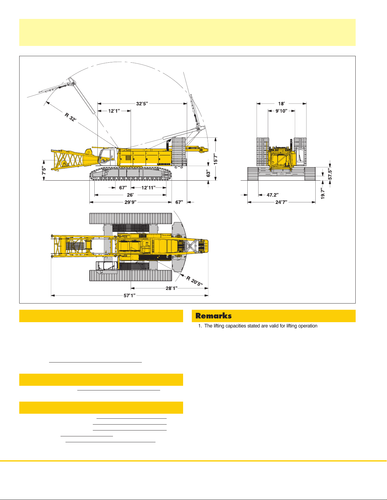
Dimensions
Basic machine with undercarriage
Operating weight
The operating weight includes the basic machine with crawlers, 2 main
winches
3
3,10
(23 ft), boom head (23 ft), boom extension (20 ft) 188,500 lbs basic
counterweight, 79,400 lbs carbody counterweight and 661,400 lbs hook
block.
To ta l weigh
0 lbs and 6
t
6 f
t main b
oom, consistin
g o
f A
–frame
a
ppr
, boom f
. 4
94,70
Ground pressure
Ground bearin
g p
ressur
e 16.8 P
Equipment
Main boo
Hig
Luffin
Max
Fixe
Auxiliary jib 66150 lbs lifting capacity
2
h r
eac
g jib
. c
ombinatio
d jib
(No. 1008.xx)
LR 1280
m
(No. 2220.xx)
h
(No. 2220.x
(No. 1916.xx)
max. l
engt
916.xx)
engt
h
h
x and 1
max. l
n boom 181 ft and l
uffin
3
296 f
391 f
312 f
g jib 312 f
6 f
t – 8
0 l
oot
bs
5 f
Remarks
1. Th
e l
iftin
g c
apacitie
s s
tate
d are v
ali
d for l
iftin
g o
peratio
n only (
corres
ponds wit
2. Crane
3. The
must
value.
4. Additional equipmen
b
SI
t
t
t
t
t
5. For
6. Working
7. Th
8. Calculatio
ANS
9. Th
(E
h c
ran
e c
lassificatio
s
tandin
g o
n f
irm
w
eigh
t o
f the l
educte
d t
o get the net l
pee
adi
i are m
apacitie
n o
f s
tabilit
s are c
2 / 2
004
iftin
d from the g
d p
easure
s are v
b
e d
e d
educte
max. wind s
r
e l
iftin
g c
I B 30.5 and ISO 4305 T
e s
tructure
N 1
3001–
, h
orizonta
g d
evic
t o
n boom (
leas
ali
y u
nde
alculate
) and t
n a
ccordin
e (
hoistin
ros
s l
e.g
iftin
g c
e r
efe
r t
d from c
d for 360 d
r load i
abl
e 2
d a
ccordin
este
d a
g t
l g
round.
g r
iftin
g c
. boom w
apacity.
o lift c
entr
e o
egree
s b
ase
.
ccordin
o F
opes
apacit
har
g t
.E.M
, hook b
alkways
t i
n o
f s
win
s o
d o
n 75% t
o F
.E.M
g t
o SAE J 9
. 1
.001
y t
o o
btai
, a
perator’
g and u
f s
wing.
ippin
. 1
.00
, c
ran
lock
, s
n a net l
uxiliar
s cab o
nde
g l
1 – 1998
87.
e g
rou
hackl
e e
iftin
y jib) must
r m
r l
oad.
oad,
–
p A
tc.)
g
anual.
1)
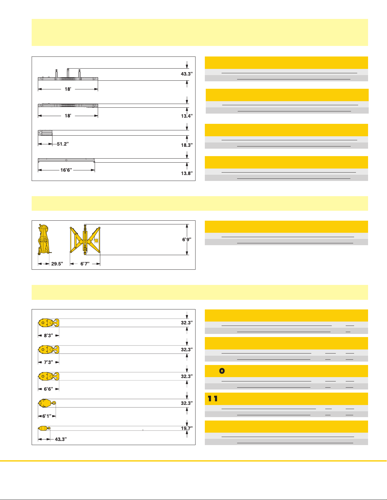
Page 3
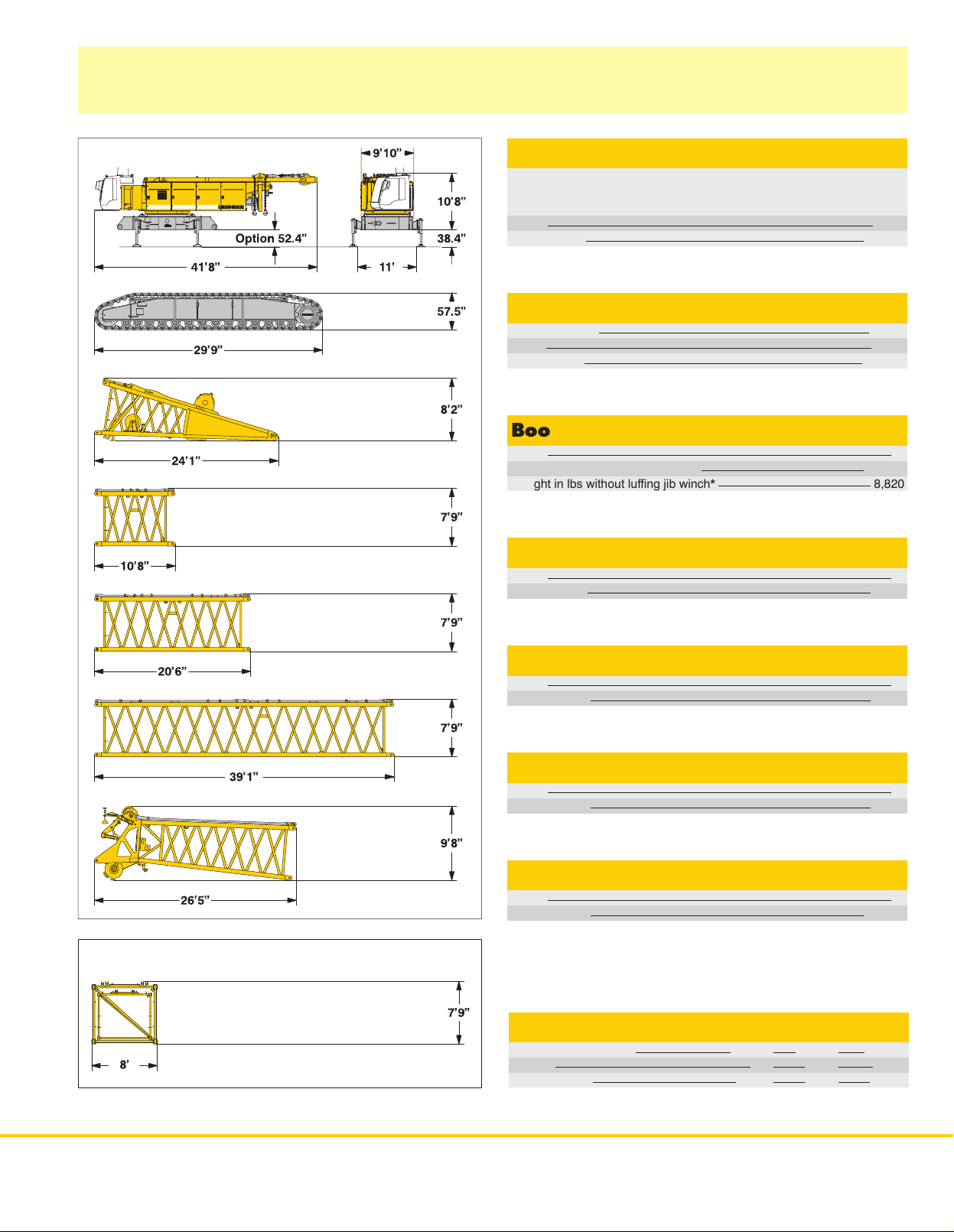
Transport dimensions and weights
Basic machine and boom (No.
2220.xx)
Basic machine
with A–frame
2182 ft, without crawlers, boom foot, basic counterweight and carbody
counterweight
Width
Weight
in lbs
, 2
x 3
3,10
0 lbs c
Crawler 2x
Flat
track shoes
Width
Weight
in lbs
ran
e w
inche
s i
ncludin
g wire r
ope
s (
max.
9”10”
91,700
47.2”
55.1”
45,300
Boom foot (No.
Width
Weight
in lbs with luf
W
eight in lbs without luf
2
220.30)
fing jib winch*
fing jib winch*
Boom section (No.
Width
Weigh
in lbs*
Boom section (No.
Width
Weight
in lbs*
Boom section (No.
Width
Weight
in lbs*
12,346
2
220.24) 10 ft
2
220.24) 20 ft
2
220.22) 38 ft
8’
8,820
8’
2,500
8’
4,135
8’
6,400
Transport option
)
*
Including pendant straps
Boom head (No.
Width
Weight
in lbs*
2
220.24)
Boom transport option
No. 2220.xx/1916.xxx
Length
W
eight in lbs*
38’/40’ 20’/20’
41’
9,100
20’6”
5,650 3,700
10,400
10’/10’
10’8”
LR 1280
8’
3
Page 4
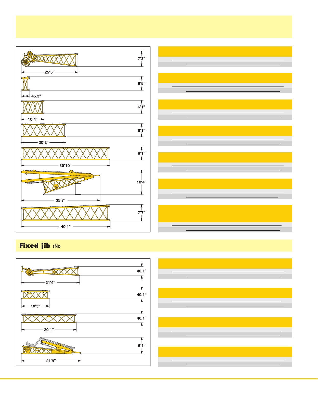
Transport dimensions and weights
Luffing jib (No.
1916.xx)
Luffing jib head (No.
Width
Weight
in lbs*
L - boom jib section (No.
Width
Weight
in lbs*
Luffing jib section (No.
Width
Weight
in lbs*
Luffing jib section (No.
Width
Weight
in lbs*
Luffing jib section (No.
Width
Weight
in lbs*
1
916.21)
1
916.22) 3ft
1
916.18) 10 ft
1
916.18) 20 ft
1
916.18) 40 ft
Luffing jib foot with A-frames (No.
Width
Weight
in lbs*
1
916.22)
3,400
1,010
1,210
1,520
2,760
14,1
6’9”
6’9”
6’9”
6’9”
6’9”
6’9”
10
Fixed jib (No.
)
*
Including pendant straps
1008.xx)
L - boom
(No.
2
section tapered
Width
Weight
in lbs*
Fixed jib head (No.
Width
Weight
in lbs*
Fixed jib section (No.
Width
Weight
in lbs*
Fixed jib section (No.
Width
Weight
in lbs*
320/1916.20) 40 ft
1
008.20)
1
008.17
)
1
008.17
)
Fixed jib foot with A-frame (No.
Width
Weight
in lbs*
1
008.20)
7’1
5,810
45”
2,060
10 ft
43.3”
660
20 ft
43.3”
1,010
59”
4,300
1”
4
LR 1280
Page 5
Transport dimensions and weights
Counterweights
Counterweight 1x
Width
Weight
in lbs
Counterweight 2x
Width
W
eight in lbs
Counterweight 10x
Width
W
eight in lbs
Carbody counterweight 4x
Width
Weight
in lbs
Mid fall (option)
5’5”
29,300
5’5”
23,370
4’6”
1
1,250
45.3
19,850
Hooks
Mid fall section (No.
Width
Weight
in lbs
1
916.32) 1.64 ft
29.5”
1,600
661,400 lbs hook block - 11 sheaves
Width
Weight
in lbs
34.6”
7,050
48.4”
12,130
330,700 lbs hook block-5sheaves
Width
Weight
in lbs
19.7”
3,500 6,200
26”
32.3”
8,800
220,500 lbs hook block-3sheaves
Width
Weight
in lbs
13.4”
2,400 4,500
19”
24.4”
6,600
110,200 lbs hook block-1sheave
Width
Weight
in lbs
1
1”
1,800 3,500
16.1”
21.3”
5,300
35,300 lbs single hook
Width
Weight
in lbs
LR 1280
19.7”
2,000
5
Page 6

Technical description
Engine
Powe
r r
atin
g a
ccordin
Engin
e type L
Fue
l t
ank
Engine complies with NRMM exhaust certification EPA / CARB Tier 3 and
97/68
EC Stage II
g to ISO 9
I
iebher
238 gal c
an
d r
eserv
249
, 450 k
r D 9508 A
W (603 HP) a
e w
7
arning
apacity with continuou
t 1900 rpm
s l
evel indicato
r
Hydraulic system
An axia
l d
luffing,
a close
minimize
a
p
ump
The
use o
Working
Oi
l tank c
isplacemen
jib l
uffin
d l
oop system. All functions ca
peak p
. All f
f s
p
ressur
apacit
g and t
ressur
ilter
s are e
yntheti
e
y
t pump s
ravel
. The main h
e an a
lectronicall
c e
nvironmentall
max. 5076 P
238 g
upplie
s the open loop h
utomati
c w
y m
y f
al
ois
t w
inche
n be o
orking pressur
onitored.
riendl
y (
biodegradable
SI
ydraulic syste
s and s
e c
win
ut–of
perated simultaneously. To
g are o
f i
s i
) oils i
m for b
perated in
ntegrate
s p
ossible.
oom
d i
Line pul
Lin
e pull (
Rop
e d
Dru
m d
Rop
e s
Rop
e c
The
w
Propulsion
Load support by th
spring loaded
The mai
system
speed
Optio
n – w
Clutch an
designed,
n
Propulsion throug
multi–dis
Fla
t t
rack shoes
Driv
e s
Main winches
l (
1st l
ayer
)
7th l
ayer
iamete
iamete
pee
apacit
inche
n w
f
eature
d
ependin
)
r
r
d f
t/mi
n 0 – 4
y i
n 7 l
ayer
s are o
i
s via a p
, m
inche
inc
h with f
d b
raking functions on the freefall syste
low wear and m
s
ulti–dis
s use p
s s
ensor
g o
utstandin
lanetar
e h
n l
reefal
g i
n t
y g
earbo
ydraulic system; additional safety factor provide
c h
oldin
g b
ressur
e c
s that a
oad
utomatically adjus
.
l s
ystem:
aintenanc
Crawlers
h a
xia
l p
isto
c b
rake, crawle
pee
d 0 – 0.87 m
r t
racks
47.2 i
n m
, h
nch
heir compac
x i
n an oil b
rake
.
ontrolled
, v
e free m
ulti–dis
otor
, h
ydraulically release
ydraulic chai
ph
t d
ath.
ariabl
t oil flow t
n t
esig
e flow h
m a
re provide
c b
rake.
ensionin
max. 4
n and easy a
ydrauli
c m
o p
rovid
e max. w
d b
y a compact
d s
prin
g l
g d
evice
.
7,40
3
3,10
2
8 m
28.7 i
1
,87
ssembly.
d b
otors
. T
oaded
0 l
0 l
nch
y a
inch
0 f
his
bs
bs
m
53
t
Luffing jib winch
Line pul
l
Rop
e d
iamete
Ji
b l
uffin
g 5
r
max. 2
3,15
2
0 m
1 sec. from 15º t
0 l
m
bs
o 7
8º
Boom winch
Line pul
l
Rop
e d
iamete
Boo
m u
r
p 137 sec. from 15º t
max. 4
2
4 m
m
8,00
0 l
bs
o 8
6º
Swing
Consists of rollerbearing with external teeth, swing drive with fixed axial
piston hydraulic motor, spring loaded and hydraulically released multi–disc
holding
brake, planetary gearbox and pinion.
Both swing modes are possible – speed control or free swing.
A multi–disc holding brake acts automatically at zero swing motion.
Swing speed from 0 – 1.8 rpm continuously variable.
Control
The
control system – developed and manufactured by Liebherr – is designed
to withstand extreme environmental conditions such as temperature,
vibration
and electromagnetic interference and to meet all requirements that
are
needed in heavy duty crane operation.
Complete machine operating data are shown on a high resolution display.
Standard operational information is displayed by means of graphical
symbols,
available).
The cranes are equipped with proportional control for all main movements,
which
The
and
Option:
Bi–directional double T–levers for simultaneous boom and luffing jib
operation.
The
levers
Remote control for assembly of counterweight and boom hinge pins.
fault indications are displayed in plain text (more
can be carried out simultaneously
crane is operated with 2 multi–directional joysticks, the right for winch I
boom, the left for winch II and swing control.
crawlers are activated by the two central foot pedals. Additionally
can be attached to the pedals.
.
than 15 languages
, hand
Noise emission
Noise emissions correspon
equipmen
t used o
utdoors.
d with 2
000/14/E
C d
irectiv
e on n
ois
e e
missio
n b
y
6LR
1280
Page 7
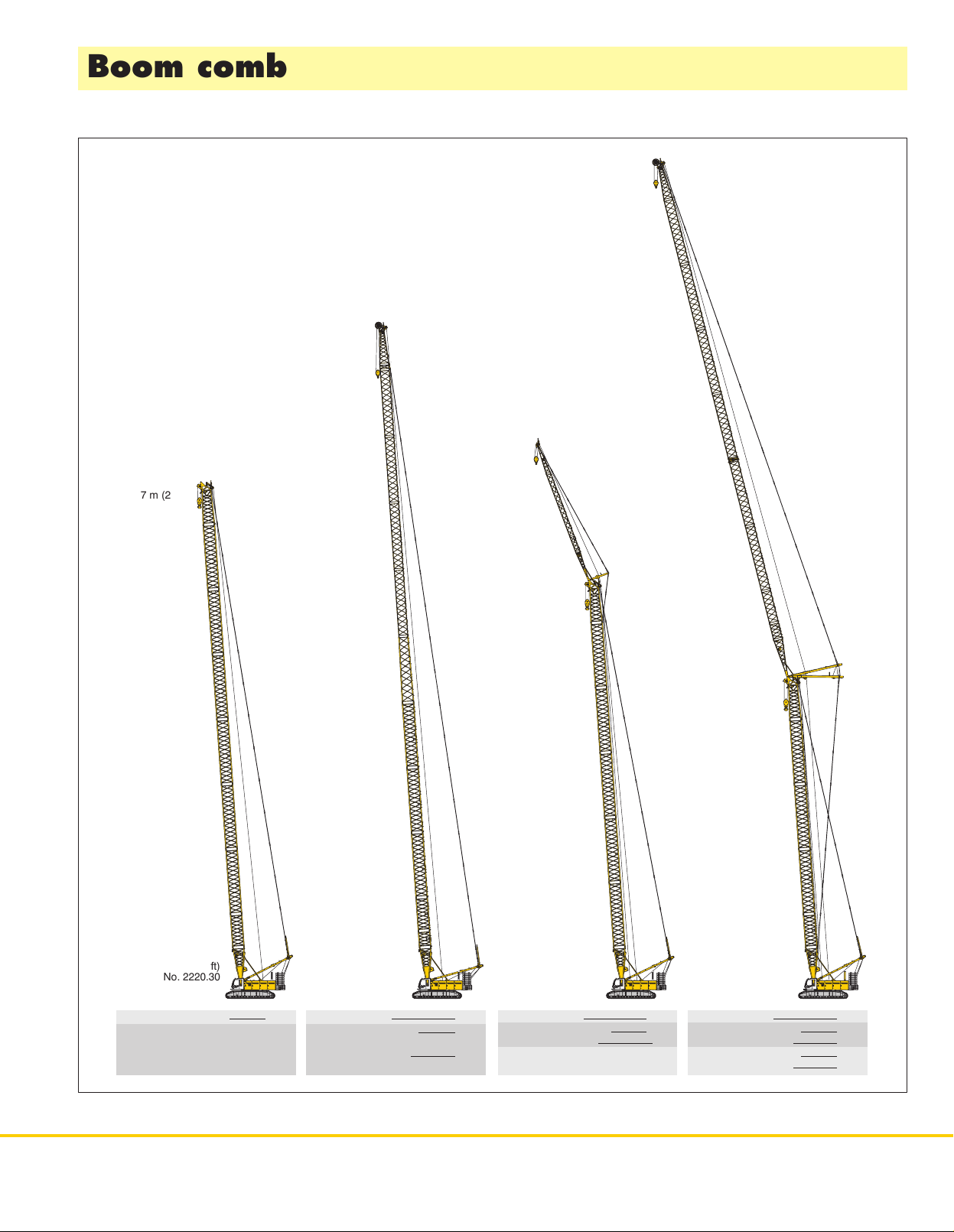
Boom combinations
7 m (23 ft)
No. 1916.21
1 m (3 ft)
No. 1916.22
12 m (40 ft)
No. 1916.18
12 m (40 ft)
No. 1916.18
7
m (23 ft)
No. 2220.24
12 m (40 ft)
1
1.7 m (38 ft)
No. 2220.22
1
1.7 m (38 ft)
No. 2220.22
1
1.7 m (38 ft)
No. 2220.22
1
1.7 m (38 ft)
No. 2220.22
1
1.7 m (38 ft)
No. 2220.22
1
1.7 m (38 ft)
No. 2220.22
6 m (10 ft)
No. 2220.22
7 m (23 ft)
No.
2220.30
No. 1916.18
12
m (40 ft) T
. 2
No
12 m (40 ft)
No. 1916.18
apered
220/1916.22
1
1.7 m (38 ft)
No. 2220.22
11.7
m (38 ft)
No. 2220.22
1
1.7 m (38 ft)
No. 2220.22
6 m (20 ft)
No. 2220.24
3 m (10 ft)
No. 2220.24
7 m (23 ft)
No. 2220.30
5.5 m (18 ft)
No. 1008.20
6 m (20 ft)
No. 1008.17
6 m (20 ft)
No. 1008.17
3 m (10 ft)
No. 1008.17
5.5 m (18 ft)
No. 1008.20
7 m (23 ft)
No. 2220.24
1
1.7 m (38 ft)
No. 2220.22
1
1.7 m (38 ft)
No. 2220.22
1
1.7 m (38 ft)
No. 2220.22
1
1.7 m (38 ft)
No. 2220.22
1
1.7 m (38 ft)
No. 2220.22
7
m (23 ft)
No. 2220.30
7 m (23 ft)
No. 1916.21
12 m (40 ft)
No. 1916.18
12 m (40 ft)
No. 1916.18
12 m (40 ft)
No. 1916.18
12 m (40 ft)
No. 1916.18
0.5 m (1.64 ft) Mid fall
No. 1916.32
12 m (40 ft)
No. 1916.18
12 m (40 ft)
No. 1916.18
No. 1916.18
No. 1916.18
6 m (20 ft)
3 m (10 ft)
7 m (18 ft)
No. 1916.22
7 m (23 ft)
No. 2220.24
1
1.7 m (38 ft)
No. 2220.22
1
1.7 m (38 ft)
No. 2220.22
1
1.7 m (38 ft)
No. 2220.22
6 m (20 ft)
No. 2220.24
No. 2220.30
7 m (23 ft)
Main boo
m No. 2
220.x
x
296 f
t Max
Max. combinatio
Mai
n boom No. 2
Tapere
g jib No. 1
Luffin
d No. 2
220/1916.xx
916.x
n 391 f
220.x
x
168 f
x
4
183 f
0 f
t
t
t
t
. c
ombinatio
Mai
n boom No. 2
d jib No. 1
Fixe
n 323 f
220.x
x
008.x
x
238 f
8
t Max
t
5 f
t
. c
ombinatio
Mai
n boom No. 2
g jib No. 1
Luffin
Mai
n boom No. 2
g jib No. 1
Luffin
n 493 f
220.x
x
916.x
220.x
916.x
x
x
181 f
312 f
x
191 f
243 f
LR
t
t
t
t
t
1280
7
Page 8
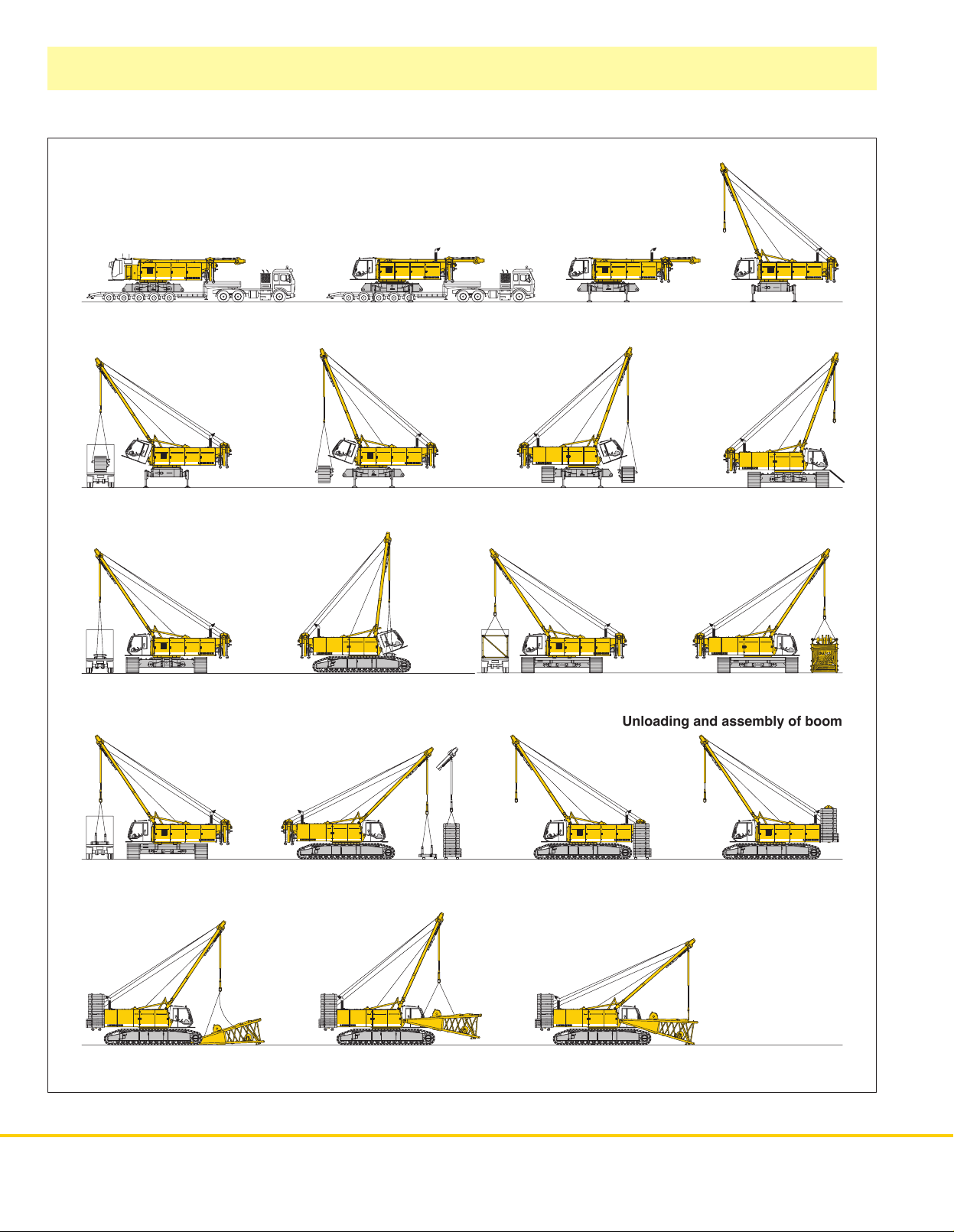
Self assembly system
Unloading
Unloading and assembly of crawlers
Unloading and assembly of carbody counterweight
of basic machine
Unloading and assembly of boom
Unloading and assembly of counterweight
Unloading and assembly of boom foot
8
LR 1280
Page 9

Erecting of main boom to working position
Assembly of boom
Reeving of hoist and luffing jib ropes
Erecting
of main boom and luffing jib
W
orking position
LR
1280
9
Page 10

Working range - main boom (No. 2220.xx) 86° -15°
188,500 lbs counterweight and 79,400 lbs carbody counterweight
Auxiliary
The maximum capacity of
the
The corresponding load
chart is programmed in the
LMI
a
uxiliar
s
ystem.
jib 66,150 lbs
y jib i
s 6
6,150 lbs
Main boom configuration
Configuration fo
Boom foot 2
Boo
m i
nsert 1
Boo
m i
nsert 2
Boo
m i
nsert 3
Boo
m h
ead 2
Boo
m l
engt
*Actual
lengths of boom sections are metric (e.g. 3 m, 6 m, 1
10
LR 1280
r boom l
ength
s (66 f
t – 296 f
t)
Length Amoun
3 f
t 1 1 1 1 1 1 1 1 1 1 1 1 1 1 1 1 1 1 1 1 1 1 1 1 1
0 f
t* 1 1 1 1 1 1 1 1 1 1 1 1
0 f
t* 1 1 1 1 1 1 1 1 1 1 1 1 1
8 f
t* 1 1 1 1 2 2 2 2 3 3 3 3 4 4 4 4 5 5 5 5 6 6 6
3 f
t 1 1 1 1 1 1 1 1 1 1 1 1 1 1 1 1 1 1 1 1 1 1 1 1 1
h i
n (
ft) 66 75 84 94 104 114 123 133 142 152 161 171 181 191 199 209 219 229 238 248 258 267 276 286 296
(Table1
– No. 2
220.xx)
t of boom e
1.7 m). The figures shown above are approximate conversions to feet.
xtensions
Page 11

Lift chart for main boom (No. 2220.xx)
Capacitie
188,50
Radius 66 84 104 123 142 161 181 199 219 238 258 276 296 Radius
Above
s i
n 1000 lbs for boom l
0 lbs c
ounterweigh
(ft) lbs lbs lbs lbs lbs lbs lbs lbs lbs lbs lbs lbs lbs (ft)
15 605.5 15
20 509.6 502.7 482.9 447.4 416.4 20
25 390.8 418.0 367.2 390.8 379.9 320.3 292.1 236.4 202.8 25
30 308.7 319.7 319.7 309.2 292.5 297.9 275.0 227.8 199.0 166.2 145.0 118.7 30
35 250.8 251.2 251.0 242.8 250.5 238.3 236.2 215.9 189.4 158.7 143.3 117.8 103.3 35
40 205.8 206.1 205.8 205.6 205.1 204.7 204.2 196.5 178.6 154.2 141.8 116.3 101.4 40
50 150.1 150.5 150.1 149.7 149.1 148.6 147.9 147.3 146.7 139.9 134.8 113.2 97.0 50
60 116.9 117.3 116.9 116.6 115.9 115.3 114.5 113.9 113.1 112.4 111.1 108.3 93.4 60
65 104.7 105.3 104.9 104.5 103.8 103.2 102.5 101.8 101.0 100.3 99.5 96.3 92.1 65
70 95.3 94.9 94.6 93.8 93.2 92.4 91.7 90.9 90.2 89.3 88.4 85.7 70
85 73.1 72.9 72.6 71.9 71.3 70.4 69.7 68.8 68.0 67.1 66.2 65.2 85
90 67.4 67.1 66.2 65.6 64.8 64.1 63.2 62.4 61.5 60.7 59.8 90
100 58.0 57.8 57.1 56.5 55.6 54.9 54.0 53.2 52.3 51.5 50.5 100
110 50.5 49.8 49.2 48.3 47.6 46.7 45.9 44.9 44.1 43.1 110
120 44.4 43.8 43.2 42.3 41.6 40.7 39.9 38.9 38.1 37.1 120
130 38.7 38.2 37.3 36.6 35.7 34.9 33.9 33.4 32.4 130
140 34.4 34.0 33.4 32.7 31.7 30.9 29.9 29.1 28.1 140
150 30.6 29.7 29.0 28.1 27.3 26.3 25.5 24.5 150
160 27.3 26.5 25.9 24.9 24.1 23.1 22.3 21.3 160
170 23.7 23.1 22.1 21.4 20.4 19.5 18.5 170
180 21.2 20.6 19.7 18.9 17.9 17.1 16.1 180
190 18.4 17.5 16.7 15.7 14.9 13.9 190
200 16.3 15.5 14.8 13.8 12.9 11.9 200
210 13.7 13.0 12.0 11.2 10.2 210
215 12.9 12.2 11.2 10.4 9.3 215
220 11.4 10.4 9.6 8.6 220
235 9.2 8.2 7.4 6.4 235
250 6.3 5.5 4.5 250
255 5.7 5.0 4.0 255
260 4.4 3.4 260
270 3.3 2.3 270
lift chart is for reference only
ength
s (66 f
t and 7
9,40
0 lbs c
t – 296 ft) – with 3
arbod
y c
ounterweight
3,10
0 lbs w
inches
Boom length in (ft)
. For actual lift duty please refer to lift chart in operator’s cab or manual.
LR
1280
11
Page 12

L - boom high reach (No.2220 / 1916.xx) 243 ft - 391 ft
Working ran ge 84° -15°
L - boom configuration with 168 ft main boom
Configuration fo
Boom foot 2
Boo
m i
nsert 1
Boo
m i
nsert 2
Boo
m i
nsert 3
Tapered 4
Luffin
g i
nsert 1
Luffin
g i
nsert 2
Luffin
g i
nsert 4
Luffin
g jib h
Max.
L – boom l
*Actual lengths of boom sections are metric (e.g. 3 m, 6 m, 8 m, 1
12
LR 1280
r L – boom l
Length Amount of boom and l
ead 2
engt
h (
ength
s (243 f
t – 391 f
t)
3 f
t 1 1 1 1 1 1 1 1 1 1 1 1 1 1 1 1
0 f
t* 1 1 1 1 1 1 1 1 1 1 1 1 1 1 1 1
0 f
t* 1 1 1 1 1 1 1 1 1 1 1 1 1 1 1 1
8 f
t* 3 3 3 3 3 3 3 3 3 3 3 3 3 3 3 3
0 f
t* 1 1 1 1 1 1 1 1 1 1 1 1 1 1 1 1
0 f
t* 1 1 1 1 1 1 1 1
0 f
t* 1 1 1 1 1 1 1 1
0 f
t* 1 1 1 1 2 2 2 2 3 3 3 3 4
6 f
t* 1 1 1 1 1 1 1 1 1 1 1 1 1 1 1 1
ft) 243 253 263 273 282 292 302 312 322 332 342 351 361 371 381 391
1.7 m, 12 m). The figures shown above are approximate conversions to feet.
(No. 2220.x
uffin
x / No. 1
g jib e
916.xx)
xtensions
Page 13

Lift chart for L - boom (No.
Main boom length 168 ft
2220 / 1916.xx)
Capacities in 1000 lbs for L – boom l
188,50
0 lbs c
ounterweigh
Radius 243 263 282 302 322 342 361 381 391 Radius
(ft) lbs lbs lbs lbs lbs lbs lbs lbs lbs (ft)
32.8 137.0 32.8
35 136.6 111.7 35
40 132.8 110.6 92.8 77.9 40
45 126.4 105.8 90.0 75.6 61.8 52.4 45
50 120.8 101.8 86.5 72.4 59.7 51.4 42.7 36.3 28.5 50
60 98.2 88.3 80.4 67.7 55.9 48.2 40.0 34.5 27.3 60
70 83.8 77.9 75.2 61.6 51.9 45.4 37.8 28.7 26.2 70
80 71.4 67.1 66.5 58.0 49.1 42.8 35.5 27.3 25.0 80
90 60.3 59.8 59.7 54.3 45.8 40.4 33.8 26.3 24.1 90
100 56.1 52.3 54.3 51.2 43.4 38.2 29.1 25.3 23.0 100
110 49.4 47.0 49.2 46.8 40.3 36.5 27.7 24.3 21.9 11 0
120 43.6 42.4 44.6 43.4 37.1 33.6 26.1 23.6 21.0 120
130 39.3 38.8 39.7 39.4 34.7 29.6 24.1 21.9 19.7 130
140 35.3 35.5 35.5 35.2 31.8 28.4 22.5 20.4 18.3 140
150 32.1 31.4 32.0 31.6 30.1 27.1 21.3 19.2 17.1 150
160 29.0 28.9 28.9 28.6 28.5 25.9 20.3 18.3 16.1 160
170 26.3 26.1 26.1 25.9 25.8 24.9 19.5 17.6 15.4 170
180 23.8 23.7 23.7 23.5 23.3 23.0 18.8 16.9 14.8 180
190 21.7 21.6 21.6 21.3 21.2 20.9 18.1 16.4 14.3 190
200 19.8 19.6 19.6 19.4 19.3 19.0 16.6 15.8 13.8 200
210 18.0 17.9 17.9 17.7 17.5 17.1 15.3 14.1 12.8 210
220 16.4 16.3 16.3 16.1 16.0 15.5 14.2 12.5 11.6 220
230 15.0 14.9 14.9 14.7 14.3 13.8 13.3 11.2 10.5 230
235 14.2 14.2 14.2 14.0 13.5 12.9 12.7 10.6 10.0 235
240 13.6 13.4 13.2 12.8 12.2 11.9 10.1 9.6 240
250 12.1 12.0 11.7 11.6 10.7 10.4 8.9 8.8 250
255 11.3 11.4 11.0 10.8 10.1 9.6 8.2 8.2 255
260 10.7 10.3 10.0 9.6 9.0 7.5 7.5 260
270 9.3 9.1 8.6 8.3 7.8 6.3 6.2 270
275 8.6 8.6 8.0 7.5 7.3 5.8 5.6 275
280 8.0 7.4 6.8 6.8 5.3 5.1 280
290 6.8 6.3 5.5 5.6 4.3 4.1 290
295 6.2 5.4 4.8 5.0 4.0 3.7 295
300 4.4 4.3 4.5 3.6 3.3 300
310 2.6 3.3 3.5 2.9 2.7 310
320 2.5 2.6 2.2 2.3 320
t and 7
9,40
ength
0 lbs c
s (243 f
t – 391 ft) – with 3
arbod
y c
ounterweight
Boom length in (ft)
3,10
0 lbs w
inches
Above lift chart is for reference only
. For actual lift duty please refer to lift chart in operator’s cab or manual.
LR 1280
13
Page 14

Working range - luffing jib (No. 1916.xx) 78°-15°
Main boom 88° -45°
Boom configuration for main boom lengths (84 ft - 199 ft)
– see t
abl
e 1 o
Jib configuration for jib lengths (66 ft - 312 ft)
Length Amount
Luf
fing jib foot
Luf
fing jib insert
Luf
fing jib insert
Luf
fing jib insert
Luf
fing jib head
Luf
fing jib length (ft)
*Actual
lengths of boom sections are metric (e.g. 3 m, 6 m, 7 m, 12 m). The figures shown above are approximate conversions to feet.
14
LR 1280
23 ft
10 ft*
20 ft*
40 ft*
23 ft
1 1 1 1 1 1 1 1 1 1 1 1 1 1 1 1 1 1 1 1 1 1 1 1 1 1
1 1 1 1 1 1 1 1 1 1 1 1 1
1 1 1 1 1 1 1 1 1 1 1 1 1 1
1 1 1 1 2 2 2 2 3 3 3 3 4 4 4 4 5 5 5 5 6 6 6 6
1 1 1 1 1 1 1 1 1 1 1 1 1 1 1 1 1 1 1 1 1 1 1 1 1 1
66 75 85 95 105 11 5 125 135 144 154 164 174 184 194 203 213 223 233 243 253 262 272 282 292 302 312
of luffing jib extensions
n page 1
0
Page 15

Lift chart - tower crane (No. 1916.xx)
Main boom angle 88°
Main boom 84 ft
Jib
Radius (ft)
27 195.2
35 186.9 149.5
45 166.0 133.4 95.4
50 152.6 124.1 91.7 68.2
60 121.1 110.8 84.0 64.3 52.2
65 112.9 104.4 80.2 62.4 50.9 39.0
75 33.4 92.5 74.0 59.5 48.7 37.5 24.0
80 86.6 70.5 57.8 47.6 36.7 23.7 15.1
100 56.5 55.8 52.4 44.0 33.8 22.1 14.2
140 37.1 39.9 39.0 28.7 19.6 12.2
180 26.7 31.2 25.5 17.2 10.6
205 22.5 23.8 15.9 9.8
235 16.5 14.6 8.7
275 10.4 7.4
290 6.8
310 5.9
66 95 135 174 203 233 272 312
lbs lbs lbs lbs lbs lbs lbs lbs
length in (ft)
Main boom 142 ft
Jib
Radius (ft)
29 163.6
40 157.8 125.2
45 149.2 121.1 85.0
55 134.7 111.8 80.5 59.3
60 126.3 108.0 78.0 58.1 45.9
65 115.8 102.9 75.9 57.0 45.6 34.7
75 83.9 92.4 70.7 54.4 44.2 33.9 23.3
85 83.0 63.3 51.8 42.8 31.8 22.9 13.8
100 66.9 56.5 48.6 40.5 30.6 21.8 13.2
140 38.1 39.5 34.9 27.0 18.9 11.5
180 27.7 28.9 24.2 16.5 10.1
205 23.4 22.5 15.3 9.3
235 17.5 14.0 8.4
275 11.2 7.2
290 6.7
310 6.1
66 95 135 174 203 233 272 312
lbs lbs lbs lbs lbs lbs lbs lbs
length in (ft)
Main boom 123 ft
Jib
Radius (ft)
28.3 163.6
35 163.6 131.6
45 157.7 125.7 88.8
55 141.7 115.0 83.1 61.6
60 124.8 110.9 80.5 60.2 48.5
65 115.7 104.6 77.9 58.9 47.7 36.1
75 81.4 93.2 72.2 56.2 46.0 35.0 24.0
80 88.2 69.8 55.0 45.0 34.6 23.9 16.0
100 59.3 56.3 50.5 41.7 31.6 22.3 13.2
140 37.9 40.3 37.1 27.7 19.3 11.6
180 27.1 31.2 24.9 16.9 10.3
205 23.8 23.4 15.6 9.5
235 17.3 14.2 8.5
275 11.1 7.3
290 6.8
310 6.1
66 95 135 174 203 233 272 312
lbs lbs lbs lbs lbs lbs lbs lbs
length in (ft)
Main boom 161 ft
Jib
Radius (ft)
29.6 131.6
55 123.1 102.2 75.9 54.4
60 118.0 96.4 73.5 53.5 42.2
75 85.4 85.1 67.3 50.7 40.6 30.6 22.0
85 77.6 62.1 48.3 39.1 29.8 21.7 13.1
100 61.0 55.8 45.0 36.9 28.8 20.7 12.7
140 39.2 36.7 30.8 25.5 18.2 11.1
180 27.6 26.1 22.2 16.0 9.6
190 24.5 21.4 15.6 9.3
205 21.3 20.3 14.9 8.9
220 18.7 14.2 8.5
235 16.8 13.6 8.1
250 12.8 7.6
275 11.2 7.0
290 6.6
310 6.0
66 95 135 174 203 233 272 312
lbs lbs lbs lbs lbs lbs lbs lbs
length in (ft)
Main boom 181 ft
Jib
Radius (ft)
30.3 129.2
40 126.6 99.1
45 120.0 97.6 71.9
55 108.1 90.2 69.4 50.6
60 103.2 86.8 67.1 49.8 39.6
70 93.5 79.4 62.8 47.8 38.6 29.8
75 84.8 76.3 60.8 46.9 38.1 29.2 21.0
85 69.8 57.1 44.8 36.6 28.2 20.8 12.8
105 33.2 49.7 40.6 33.8 26.5 19.6 12.2
140 38.5 33.5 28.7 23.6 17.5 10.8
180 27.1 23.9 20.7 15.5 9.3
205 21.6 18.8 14.4 8.6
235 16.6 13.2 7.8
275 11.2 6.8
290 6.4
310 5.8
Capacitie
For
a
ctua
66 95 135 174 203 233 272 312
lbs lbs lbs lbs lbs lbs lbs lbs
s i
n 1000 lbs with l
l lift duty and c
uffin
omplet
length in (ft)
g jib (No. 1
e c
har
t with all a
916.xx
vailabl
) 1
88,50
e c
0 lbs c
onfiguration
ounterweigh
s p
leas
Main boom 199 ft
Jib
b o
. A
r m
length in (ft)
bov
e lift c
anual.
har
Radius (ft)
31 99.2
40 99.2 85.3
45 97.5 82.6 72.0
50 95.2 79.7 70.1 60.7
55 91.3 76.6 67.7 59.2 48.4 44.5
60 88.0 73.8 65.3 57.4 47.4 44.0 41.2
70 80.1 67.9 61.1 54.2 45.3 42.2 39.8
75 77.6 63.3 59.0 52.5 44.4 41.3 38.9
105 31.9 47.2 43.7 37.9 35.9 34.2
125 32.4 38.1 33.8 31.7 30.4
140 34.9 30.5 29.5 28.5
150 29.1 27.9 26.9
170 26.4 25.3 24.4
175 24.8 23.9
180 24.2 23.4
190 22.4
t + 7
9,40
e r
efe
r t
o l
66 95 115 135 164 174 184
lbs lbs lbs lbs lbs lbs lbs
0 lbs c
arbod
y c
t i
n o
ounterweight
perator’s ca
ift char
t i
s for r
eferenc
LR 1280
e o
nly.
15
Page 16

Lift chart - luffing jib (No. 1916.xx)
Main boom angle 83°
Main boom 84 ft
Jib
Radius (ft)
40 190.7
50 157.6 138.4
65 112.7 112.2 86.1
75 94.3 94.0 78.9 61.8
80 84.9 86.8 75.4 60.1
85 80.6 72.8 58.7 48.3
90 75.2 68.4 57.1 47.2 36.0
105 60.5 57.6 53.3 44.5 34.2 22.5
110 33.4 54.6 51.8 43.7 33.6 22.2
115 51.8 50.5 43.0 31.6 21.8 14.2
145 38.5 40.5 39.3 28.8 19.9 12.7
185 28.3 29.0 25.9 17.5 11.0
215 22.7 22.8 16.0 10.0
240 17.9 14.9 9.0
280 11.4 7.6
320 6.1
66 95 135 174 203 233 272 312
lbs lbs lbs lbs lbs lbs lbs lbs
length in (ft)
Main boom 142 ft
Jib
Radius (ft)
47.1 163.5
60 121.8 119.9
70 100.4 99.8 79.7
80 85.2 84.7 75.3 56.0
85 79.0 78.6 72.5 55.4
90 73.3 70.4 54.2 43.7
100 64.5 62.1 51.9 42.6 31.5
110 57.3 56.6 49.9 41.2 30.7 21.2
115 54.3 53.6 48.9 40.5 30.2 21.2
120 50.9 47.9 39.9 29.7 21.0 13.9
155 32.0 36.1 35.4 26.7 18.8 11.5
190 27.6 27.0 24.6 16.8 10.2
220 22.0 21.2 15.4 9.3
250 17.4 14.2 8.4
285 12.0 7.5
325 6.3
66 95 135 174 203 233 272 312
lbs lbs lbs lbs lbs lbs lbs lbs
length in (ft)
Main boom 123 ft
Jib
Radius (ft)
44.7 163.6
55 137.3 127.5
65 111.1 110.5 82.9
80 85.9 85.5 75.8 58.0
85 79.7 79.4 73.0 56.6 45.3
95 69.3 67.0 54.1 44.3 33.6
110 57.9 56.9 50.9 42.1 31.3 22.0
120 51.4 48.7 40.8 30.3 21.4 13.1
150 38.9 38.1 37.4 27.6 19.4 11.9
190 28.0 27.4 25.0 17.0 10.4
215 23.0 22.3 15.8 9.6
245 18.2 14.5 8.6
260 13.6 8.2
285 11.8 7.5
300 7.0
320 6.3
66 95 135 174 203 233 272 312
lbs lbs lbs lbs lbs lbs lbs lbs
length in (ft)
Main boom 161 ft
Jib
Radius (ft)
49.3 131.6
60 120.6 112.0
70 99.5 98.7 75.1
85 78.3 77.8 70.2 52.6
90 72.9 72.6 68.1 51.6 41.1
100 63.8 62.7 49.7 40.3 30.0
110 56.8 56.0 47.7 39.1 29.3 20.8
120 33.4 50.3 45.7 37.9 28.6 20.3
125 47.8 44.7 37.4 28.1 20.0 12.1
150 38.0 37.2 34.7 26.2 18.5 11.4
195 26.3 25.7 23.4 16.1 9.8
225 20.9 20.2 14.8 8.9
250 17.1 13.8 8.2
290 11.8 7.2
310 6.7
325 6.2
66 95 135 174 203 233 272 312
lbs lbs lbs lbs lbs lbs lbs lbs
length in (ft)
Main boom 181 ft
Jib
Radius (ft)
51.7 128.1
65 107.8 97.8
75 90.3 89.6 70.1
85 77.4 76.9 67.0 49.3
95 33.1 67.1 62.7 47.9 38.8
105 59.4 58.5 46.0 37.9 28.5
115 53.1 52.3 44.3 36.8 27.8 19.6
120 50.3 49.6 43.4 36.2 27.4 19.5
130 44.9 41.3 35.2 26.6 19.0 11.7
160 34.6 33.7 31.3 24.5 17.4 10.7
200 25.0 24.4 21.9 15.5 9.4
225 20.6 19.8 14.5 8.7
255 16.3 13.3 7.8
295 11.7 6.9
310 6.5
330 5.9
Capacitie
For
a
ctua
16
LR 1280
66 95 135 174 203 233 272 312
lbs lbs lbs lbs lbs lbs lbs lbs
s i
n 1000 lbs with l
l lift duty and c
uffin
omplet
length in (ft)
g jib (No. 1
e c
har
t with all a
916.xx
) 1
vailabl
88,50
e c
onfiguration
0 lbs c
ounterweigh
s p
leas
Main boom 199 ft
Jib
b o
. A
r m
length in (ft)
bov
e lift c
anual.
har
Radius (ft)
54 99.2
65 97.7 83.7
70 94.1 81.5 71.1
75 89.3 78.6 69.9 60.1
85 76.5 73.1 64.5 58.0 47.6
90 71.3 70.4 63.6 56.5 47.1 43.7 40.7
95 66.7 65.3 61.5 55.1 46.2 43.0 40.4
100 62.2 59.7 53.9 45.3 42.3 39.8
120 49.7 49.4 48.4 41.4 39.2 37.0
130 44.7 44.3 39.3 37.2 35.5
140 40.7 40.4 37.6 35.5 33.9
150 37.0 35.5 34.0 32.1
160 34.0 33.5 31.2 30.7
190 26.7 26.5 26.3
200 24.6 24.5
205 23.6
t + 7
9,40
e r
efe
r t
o l
66 95 115 135 164 174 184
lbs lbs lbs lbs lbs lbs lbs
0 lbs c
arbod
y c
t i
n o
ounterweight
perator’s ca
ift char
t i
s for r
eferenc
e o
nly.
Page 17

Lift chart - luffing jib (No. 1916.xx)
Main boom angle 75°
Main boom 84 ft
Jib
Radius (ft)
65 108.0
75 90.5 89.8
90 72.3 71.8 70.8
95 33.4 67.2 66.2
110 56.2 55.3 54.3
120 50.4 49.7 48.7 43.1
135 43.0 42.0 41.2 30.3
150 37.6 36.7 36.0 28.9 19.8
160 34.6 33.8 33.1 28.2 19.4
165 32.5 31.8 27.8 19.1 12.7
200 25.1 24.5 23.6 17.2 10.7
225 20.6 19.9 16.0 9.9
255 16.3 14.8 8.8
295 11.8 7.6
310 7.1
330 6.4
66 95 135 174 203 233 272 312
lbs lbs lbs lbs lbs lbs lbs lbs
length in (ft)
Main boom 142 ft
Jib
Radius (ft)
80 78.2
90 67.7 66.8
105 55.9 55.3 54.2
125 44.7 43.6 42.4
135 40.6 39.6 38.5 37.7
150 34.7 33.6 32.9 28.1
165 30.8 29.7 28.9 27.1 17.9
175 28.4 27.5 26.7 25.7 17.7
180 26.5 25.7 24.7 17.5 11.6
210 21.3 20.7 19.7 16.3 10.2
240 16.9 16.0 14.9 9.3
270 13.1 12.1 8.4
290 10.5 7.8
305 9.4 7.5
320 7.1
345 6.0
66 95 135 174 203 233 272 312
lbs lbs lbs lbs lbs lbs lbs lbs
length in (ft)
Main boom 123 ft
Jib
Radius (ft)
75 86.8
85 74.5 73.6
100 60.9 60.4 59.3
120 48.3 47.3 46.2
130 43.7 42.9 41.7 40.3
145 37.4 36.3 35.5 28.5
160 33.0 32.0 31.3 27.5 18.5
170 30.5 29.6 28.8 26.9 18.2
175 28.5 27.7 26.5 18.0 11.9
205 22.9 22.2 21.3 16.7 10.5
235 18.1 17.3 15.5 9.5
265 14.2 13.2 8.5
280 11.9 8.1
305 10.0 7.4
320 7.0
340 6.4
66 95 135 174 203 233 272 312
lbs lbs lbs lbs lbs lbs lbs lbs
length in (ft)
Main boom 161 ft
Jib
Radius (ft)
85 70.6
95 61.7 60.7
110 51.4 50.8 49.6
130 41.3 40.3 39.0
140 37.6 36.7 35.5 34.6
155 32.3 31.1 30.3 26.8
170 28.6 27.6 26.8 25.7 17.1
180 26.5 25.5 24.7 23.7 16.9
185 24.6 23.8 22.8 16.7 11.0
210 20.5 19.3 18.9 15.9 9.9
215 19.8 18.5 18.2 15.7 9.7
245 15.6 14.8 13.6 8.9
275 12.0 11.0 8.1
310 8.5 7.3
330 6.3
350 5.3
66 95 135 174 203 233 272 312
lbs lbs lbs lbs lbs lbs lbs lbs
length in (ft)
Main boom 181 ft
Jib
g jib (No. 1
e c
har
t with all a
length in (ft)
916.xx
vailabl
) 1
88,50
0 lbs c
e c
onfiguration
Radius (ft)
85 66.4
100 56.1 55.1
115 47.1 46.4 45.2
135 38.0 36.9 35.7
145 34.7 33.7 32.6 31.7
160 29.8 28.6 27.8 25.4
175 26.5 25.4 24.6 23.5 16.3
185 24.5 23.5 22.7 21.7 16.2
190 22.6 21.9 20.8 16.1 10.5
220 18.3 17.6 16.6 15.0 9.4
250 14.3 13.5 12.1 8.7
280 10.9 9.9 7.9
300 8.5 6.8
315 7.6 6.0
330 5.3
355 4.3
Capacitie
For
a
ctua
66 95 135 174 203 233 272 312
lbs lbs lbs lbs lbs lbs lbs lbs
s i
n 1000 lbs with l
l lift duty and c
uffin
omplet
ounterweigh
s p
leas
Main boom 199 ft
Jib
b o
. A
r m
length in (ft)
bov
e l
ift char
anual.
Radius (ft)
89.9 61.8
105 51.1 50.1
115 45.6 44.8 44.1
120 43.2 42.5 41.8 41.2
135 36.7 36.1 35.5 34.6
140 35.0 34.4 33.9 33.1 32.7 32.3
150 32.1 31.6 31.1 30.3 29.8 29.6
170 26.8 26.4 25.6 25.2 23.3
180 24.4 23.7 23.3 22.4
190 22.7 22.0 21.6 20.8
200 20.5 20.1 19.3
215 18.4 18.1 17.4
220 17.4 16.6
225 16.8 15.9
230 15.2
235 14.5
t + 7
9,40
e r
efe
r t
o l
66 95 115 135 164 174 184
lbs lbs lbs lbs lbs lbs lbs
0 lbs c
arbod
y c
t i
n o
ounterweight
perator’s ca
ift char
t i
s for r
eferenc
LR 1280
e o
nly.
17
Page 18

Lift chart - luffing jib (No. 1916.xx)
Main boom angle 65°
Main boom 84 ft
Jib
Radius (ft)
84 74.6
105 56.7 56.1
125 45.3 44.3
135 33.4 40.2
150 35.2 34.1
165 31.2 30.2 29.4
170 30.0 29.0 28.3
180 26.9 26.1 25.1
205 22.5 21.8 20.8 16.9
210 21.7 21.0 20.1 16.9
225 19.0 18.1 16.2 10.3
240 17.2 16.3 15.3 9.6
265 13.8 12.8 8.8
305 9.7 7.6
320 7.3
340 6.6
66 95 135 174 203 233 272 312
lbs lbs lbs lbs lbs lbs lbs lbs
length in (ft)
Main boom 142 ft
Jib
Radius (ft)
108.1 48.1
130 38.2 37.5
145 32.7
150 31.3 30.1
160 28.8 27.7
175 24.6 23.4
185 22.8 21.6
200 20.4 19.3 18.5
205 18.7 17.8 16.7
230 15.7 14.9 13.9 12.6
235 15.1 14.4 13.4 12.1
250 13.0 12.0 10.8 8.8
265 11.7 10.8 9.6 7.7
295 8.6 7.5 5.9
330 5.6 4.2
370 2.7
66 95 135 174 203 233 272 312
lbs lbs lbs lbs lbs lbs lbs lbs
length in (ft)
Main boom 123 ft
Jib
Radius (ft)
99.8 55.9
120 44.5
125 41.4
140 35.9 34.9
160 30.3 29.5
165 28.3 27.1
180 25.2 24.1 23.2
190 23.4 22.4 21.6
200 20.8 20.0 19.0
220 18.1 17.4 16.3 15.1
225 17.5 16.8 15.8 14.6
245 14.6 13.7 12.5 9.2
255 13.7 12.8 11.6 8.9
285 10.4 9.3 8.1
320 7.1 6.0
360 4.0
66 105 135 174 203 233 272 312
lbs lbs lbs lbs lbs lbs lbs lbs
length in (ft)
Main boom 161 ft
Jib
Radius (ft)
116 41.8
135 34.6 33.7
140 33.1 32.2
160 27.1 25.9
170 25.0 23.9
180 22.1 20.8
200 19.1 17.9 17.0
205 18.4 17.3 16.4
215 16.1 15.2 14.1
235 13.9 13.2 12.1 10.2
245 13.0 12.3 11.2 9.4
260 11.0 10.0 8.4 6.4
270 10.3 9.3 7.7 5.7
300 7.4 6.0 4.1
340 4.2 2.4
350 2.1
66 95 135 174 203 233 272 312
lbs lbs lbs lbs lbs lbs lbs lbs
length in (ft)
Main boom 181 ft
Jib
Radius (ft)
124.4 35.9
145 29.6 28.6
165 24.2 22.8
175 22.3 21.1
190 18.8 17.5
205 16.8 15.6 14.7
215 15.6 14.5 13.6
225 13.5 12.6 11.0
245 11.7 10.9 9.5 7.4
250 11.2 10.5 9.1 7.1
270 9.0 7.9 5.8 3.8
280 8.4 7.3 5.3 3.3
305 6.0 4.1 2.2
310 5.7 3.9
330 3.2
345 2.7
Capacitie
For
a
ctua
18
LR 1280
66 95 135 174 203 233 272 312
lbs lbs lbs lbs lbs lbs lbs lbs
s i
n 1000 lbs with l
l lift duty and c
uffin
omplet
length in (ft)
g jib (No. 1
e c
har
t with all a
916.xx
) 1
vailabl
88,50
e c
onfiguration
0 lbs c
ounterweigh
s p
leas
Main boom 199 ft
Jib
b o
. A
r m
length in (ft)
bov
e lift c
anual.
har
Radius (ft)
132.3 30.9
150 26.3 25.2
155 25.2 24.2
165 22.3 21.6
175 20.6 19.9 19.3
180 19.8 19.1 18.5
190 17.7 17.1 16.2
195 17.0 16.5 15.6 15.1
200 16.4 15.9 15.0 14.6 14.1
210 14.8 13.9 13.5 13.1
220 13.7 12.9 12.5 12.2
230 12.0 11.6 11.3
250 10.4 10.0 9.7
260 9.2 9.0
265 8.7
270 8.3
t + 7
9,40
e r
efe
r t
o l
66 95 115 135 164 174 184
lbs lbs lbs lbs lbs lbs lbs
0 lbs c
arbod
y c
t i
n o
ounterweight
perator’s ca
ift char
t i
s for r
eferenc
e o
nly.
Page 19

Lift chart - luffing jib (No. 1916.xx)
Main boom angle 45°
Main boom 84 ft
Jib
Radius (ft)
122.9 42.1
130 39.2
149 32.4
160 29.5
180 24.3
200 21.0
215 18.0
235 15.6
240 14.4
260 12.6 11.6
265 12.2 11.2
295 9.1 8.0
325 6.2 5.0
330 6.0 4.9
350 3.9
370 3.1
66 95 135 174 203 233 272 312
lbs lbs lbs lbs lbs lbs lbs lbs
length in (ft)
Main boom 142 ft
Jib
Radius (ft)
164 22.0
170 21.0
190 17.1
200 15.8
225 12.1
235 11.2
255 8.5
265 7.9
275 7.3
280 6.2
290 5.7
300 5.2
305 4.9 3.9
315 3.4
325 3.0
330 2.8
66 95 135 174 203 233
lbs lbs lbs lbs lbs lbs
length in (ft)
Main boom 123 ft
Jib
Radius (ft)
150.1 27.8
160 25.5
175 21.8
185 20.2
210 15.8
225 14.2
240 11.6
260 10.1
265 8.9
285 7.7
290 7.4 6.3
300 5.8
320 4.8 3.5
330 3.2
340 2.8
355 2.2
66 95 135 174 203 233 272
lbs lbs lbs lbs lbs lbs lbs
length in (ft)
Main boom 161 ft
Jib
Radius (ft)
177.2 17.3
180 17.0
185 16.3
205 13.1
210 12.6
215 12.1
235 9.2
240 8.9
245 8.6
250 8.2
270 5.8
280 5.3
290 4.8
295 3.7
300 3.5
315 2.9
66 95 135 174 203
lbs lbs lbs lbs lbs
length in (ft)
Main boom 181 ft
Radius (ft)
191.1 12.9
195 12.5
200 12.0
220 9.3
225 8.9
250 6.1
260 5.5
265 5.2
280 3.0
290 2.7
300 2.4
305 2.2
Capacitie
For
a
ctua
66 95 135 174
lbs lbs lbs lbs
s i
n 1000 lbs with l
l lift duty and c
omplet
uffin
g jib (No. 1
e c
Jib
length in (ft)
har
t with all a
916.xx
vailabl
) 1
88,50
e c
0 lbs c
ounterweigh
onfiguration
s p
Main boom 199 ft
66 95 115 135
lbs lbs lbs lbs
arbod
ift char
y c
t i
n o
perator’s ca
leas
Radius (ft)
204.4 9.1
205 9.1
210 8.7
230 6.3
235 6.1
240 5.8
245 4.7
250 4.5
260 4.1
265 3.0
270 2.9
275 2.7
t + 7
9,40
efe
r t
0 lbs c
o l
e r
ounterweight
b o
Jib
length in (ft)
. A
bov
e lift c
r m
anual.
har
t i
s for r
eferenc
LR
1280
e o
nly.
19
Page 20

Working range - fixed jib (No. 1008.xx) 15° and 30°
Main boom 88°-30°
Boom configuration for boom lengths (66 ft - 248 ft) –
see t
abl
e 1 o
Fixed jib configuration for fixed jib lengths (36 ft - 85 ft)
Length Amount
Fixed jib foot
Fixed jib insert
Fixed jib insert
Fixed jib head
Fixed jib length (ft)
*Actual
lengths of boom sections are metric (e.g. 3 m, 6 m). The figures shown above are approximate conversions to feet.
20
LR 1280
18 ft
10 ft*
20 ft*
18 ft
1 1 1 1 1 1
1 1 1
1 1 1 1 1 1
36 46 56 66 75 85
of fixed jib extensions
1 1 2 2
n page 1
0
Page 21

Lift chart - fixed jib (No. 1008.xx)
Offset 15°
Main boom 66 ft
Fixed
jib length in (ft)
36 46 66 85
Radius (ft)
19.1 81.2
25 81.2 81.0
35 81.2 80.9 75.6
40 81.2 80.9 69.1 51.3
60 78.7 67.1 51.2 41.6
70 72.5 59.4 45.1 36.7
80 64.7 53.5 39.9 33.4
90 59.9 48.1 36.1 30.6
95 56.9 46.0 34.3 29.2
105 42.1 31.8 26.9
125 28.3 22.7
145 19.9
lbs lbs lbs lbs
Main boom 152 ft
Fixed
jib length in (ft)
36 46 66 85
Radius (ft)
22.2 81.2
30 81.1 81.0
35 81.0 81.0 74.3
45 81.0 81.2 69.8 48.7
60 81.0 81.1 61.8 45.3
80 78.5 72.2 52.0 39.8
100 57.1 58.0 44.6 34.2
140 34.1 34.8 34.6 27.7
170 24.3 25.0 26.1 23.7
180 22.4 23.6 22.7
200 19.1 20.1
220 16.4
lbs lbs lbs lbs
Main boom 94 ft
Fixed
jib length in (ft)
36 46 66 85
Radius (ft)
20.1 80.9
25 81.0 81.0
35 81.1 81.0 75.8
40 81.1 81.0 71.4 51.2
60 80.9 73.8 56.3 43.5
80 76.7 60.2 44.9 35.5
100 59.6 51.4 37.4 30.9
110 52.1 47.6 34.5 28.5
120 45.9 44.5 32.0 26.7
130 41.5 31.4 24.8
150 28.0 21.8
170 19.7
lbs lbs lbs lbs
Main boom 181 ft
Fixed
jib length in (ft)
36 46 66 85
Radius (ft)
23.1 81.0
30 80.9 80.9
35 81.0 81.1 72.0
45 81.2 81.2 69.7 47.9
60 81.2 81.2 63.5 45.1
80 77.4 75.4 55.1 40.7
120 42.3 43.1 41.7 33.4
160 26.0 26.7 27.9 26.9
200 16.3 16.9 18.0 18.9
205 15.9 17.0 18.0
225 13.6 14.5
245 11.5
lbs lbs lbs lbs
Main boom 123 ft
Fixed
jib length in (ft)
36 46 66 85
Radius (ft)
21.1 80.8
25 81.0 81.2
35 80.9 81.2 75.5
45 80.9 81.1 68.8 49.1
60 81.0 77.7 59.1 45.0
80 78.8 67.5 48.4 38.1
100 58.6 58.2 40.9 33.4
120 45.0 45.7 35.6 29.0
145 33.5 34.2 31.6 24.9
155 30.8 30.6 23.5
175 26.2 21.3
195 19.6
lbs lbs lbs lbs
Main boom 199 ft
Fixed
jib length in (ft)
36 46 66 85
Radius (ft)
23.8 81.2
30 80.9 81.1
40 80.9 81.0 67.2
45 81.0 81.0 67.3 46.9
60 81.1 81.1 63.5 44.5
100 55.2 56.1 48.9 37.1
140 32.2 32.9 34.1 31.2
180 19.8 20.4 21.6 22.6
215 12.9 13.4 14.5 15.4
225 11.8 12.8 13.7
245 9.9 10.8
265 8.3
lbs lbs lbs lbs
Main boom 219 ft
Fixed
jib length in (ft)
36 46 66 85
Radius (ft)
24.5 81.2
30 81.0 75.9
40 80.9 77.4 59.4
45 81.0 77.4 60.0 46.1
80 75.8 77.0 56.4 41.1
120 40.5 41.4 42.9 33.8
160 24.2 24.9 26.1 27.2
200 14.6 15.1 16.2 17.2
230 9.6 10.1 11.1 12.0
240 8.7 9.7 10.6
260 7.1 8.0
280 5.7
Capacities i
For
a
ctua
lbs lbs lbs lbs
n 1000 l
l lift duty and c
bs with fixe
omplet
d j
e c
Main boom 238 ft
Radius (ft)
ib (No. 1008.xx) 188,50
har
t with all a
vailabl
e c
Main boom 248 ft
Fixed
jib length in (ft)
36 46 66 85
lbs lbs lbs lbs
25.1 76.2
30 76.0 69.6
40 75.6 69.9 54.9
45 75.9 69.9 54.9 44.4
80 73.8 70.2 54.3 40.7
120 39.7 40.5 42.1 34.7
160 23.4 24.0 25.3 26.5
200 13.7 14.3 15.4 16.4
245 6.7 7.2 8.2 9.1
255 5.9 6.9 7.8
275 4.6 5.5
295 3.4
0 l
bs counterweight + 79,400 lbs carbody counterweight. Above lift chart is for referenc
onfiguration
s p
leas
e r
efe
r t
o l
ift char
t i
n o
Radius (ft)
perator’s ca
25.5 73.3
30 73.0 66.7
35 72.4 66.7 57.3
40 72.3 66.9 57.5
80 72.1 62.6 57.6
120 39.2 40.1 41.0
160 22.9 23.5 24.3
200 13.2 13.8 14.4
240 6.8 7.3 7.9
255 4.9 5.4 6.0
265 4.3 4.8
275 3.7
b o
r m
Fixed
jib length in (ft)
36 46 56
lbs lbs lbs
anual.
LR
e o
1280
nly.
21
Page 22

Lift chart - fixed jib (No. 1008.xx)
Offset 30°
Main boom 66 ft
Fixed
jib length in (ft)
36 46 66 85
Radius (ft)
27.8 81.2
35 81.2 66.4
50 66.5 55.6 41.2
60 62.0 49.0 36.4 31.4
70 55.5 44.2 32.9 28.0
80 50.8 40.6 31.1 25.1
90 47.4 37.5 28.6 22.8
100 45.1 35.4 26.5 21.1
110 34.0 24.8 19.5
130 22.8 17.2
140 16.5
150 16.1
lbs lbs lbs lbs
Main boom 152 ft
Fixed
jib length in (ft)
36 46 66 85
Radius (ft)
30.9 81.0
40 80.8 66.3
50 78.6 62.2 42.2
65 70.1 55.4 38.0 30.8
80 64.0 50.1 34.4 27.6
100 58.0 44.9 31.6 24.6
120 44.2 40.7 29.2 21.9
140 34.5 35.4 26.7 20.0
175 23.1 23.8 23.7 17.6
185 21.3 22.7 17.1
205 18.3 16.4
225 15.7
lbs lbs lbs lbs
Main boom 94 ft
Fixed
jib length in (ft)
36 46 66 85
Radius (ft)
28.8 81.0
35 81.1 67.2
50 72.1 58.8 41.8
60 64.9 53.1 37.8 29.2
80 56.8 44.6 32.3 26.1
90 53.0 41.4 30.9 24.2
100 49.7 39.0 28.8 22.4
110 47.4 36.9 27.1 21.0
120 45.7 35.4 25.6 19.7
130 34.4 24.4 18.7
150 23.0 17.0
170 16.2
lbs lbs lbs lbs
Main boom 181 ft
Fixed
jib length in (ft)
36 46 66 85
Radius (ft)
31.9 81.0
40 81.2 66.4
55 77.8 61.0 41.2
65 72.4 57.1 38.5 30.1
100 57.0 46.8 32.5 25.1
140 33.5 34.3 28.0 21.0
160 26.4 27.2 26.1 19.3
180 20.9 21.6 23.0 18.2
200 16.4 17.1 18.4 17.2
205 16.1 17.4 17.0
225 13.7 14.9
245 11.7
lbs lbs lbs lbs
Main boom 123 ft
Fixed
jib length in (ft)
36 46 66 85
Radius (ft)
29.8 81.1
40 80.9 66.0
50 75.5 60.8 42.4
65 65.3 53.5 37.3 30.5
80 62.2 47.6 33.4 27.1
100 54.4 42.0 30.8 23.6
120 45.5 38.1 27.5 21.0
140 35.8 35.3 25.1 18.9
150 31.9 32.8 24.2 18.2
160 29.3 23.5 17.4
180 22.7 16.4
200 16.0
lbs lbs lbs lbs
Main boom 199 ft
Fixed
jib length in (ft)
36 46 66 85
Radius (ft)
32.5 79.8
40 79.9 64.7
55 79.2 61.6 41.4
65 73.8 58.1 38.9 27.8
100 56.3 48.0 33.1 25.5
140 32.8 33.6 28.9 21.4
180 20.1 20.9 22.3 18.6
200 15.8 16.4 17.7 17.6
215 13.0 13.6 14.9 16.0
225 11.9 13.1 14.3
245 10.0 11.2
265 8.4
lbs lbs lbs lbs
Main boom 219 ft
Fixed
jib length in (ft)
36 46 66 85
Radius (ft)
33.2 74.3
40 74.3 65.0
55 75.2 60.5 41.6
65 73.2 59.0 39.3 25.7
100 55.5 49.2 33.4 25.5
140 31.9 32.8 29.8 21.9
180 19.2 20.0 21.5 19.1
220 11.3 11.9 13.2 14.3
230 9.7 10.3 11.5 12.7
240 8.8 10.0 11.1
260 7.2 8.3
280 5.9
Capacities i
For
a
ctua
22 LR
1280
lbs lbs lbs lbs
n 1000 l
l lift duty and c
bs with fixe
omplet
d j
e c
Main boom 238 ft
Radius (ft)
ib (No. 1008.xx) 188,50
har
t with all a
vailabl
e c
Main boom 248 ft
Fixed
jib length in (ft)
36 46 66 85
lbs lbs lbs lbs
33.8 67.3
40 67.4 59.9
55 68.0 56.0 41.3
65 68.5 56.2 39.5 28.5
100 54.8 50.5 33.6 24.8
140 31.1 32.1 30.4 22.3
180 18.4 19.2 20.8 19.6
220 10.5 11.1 12.4 13.6
245 6.8 7.4 8.6 9.7
255 6.1 7.2 8.3
275 4.8 5.8
295 3.6
0 l
bs counterweight + 79,400 lbs carbody counterweight. Above lift chart is for referenc
onfiguration
s p
leas
e r
efe
r t
o l
ift char
t i
n o
Radius (ft)
perator’s ca
34.2 64.8
45 60.0 53.4
50 60.1 53.5 49.8
55 60.2 53.7 49.2 41.2
100 54.4 51.0 40.8 33.8
140 30.6 31.6 32.7 30.6
180 18.0 18.7 19.6 20.3
220 10.0 10.7 11.4 12.0
255 5.0 5.6 6.2 6.8
265 4.4 5.0 5.5
275 3.8 4.4
285 3.2
b o
r m
Fixed
jib length in (ft)
36 46 56 66
lbs lbs lbs lbs
anual.
11
e o
nly.
Page 23

Notice
LR 1280
23
Page 24

Liebherr-Werk Nenzing GmbH
P.O. Box 10, A-6710 Nenzing/Austria
Tel.: +43 50809 41 - 473
Fax: +43 50809 41 - 499
crawler.crane@liebherr.com
www.liebherr.com
1280 – 10223040 – 02/2008 Subject to change without notice.
LR
 Loading...