

Page 1
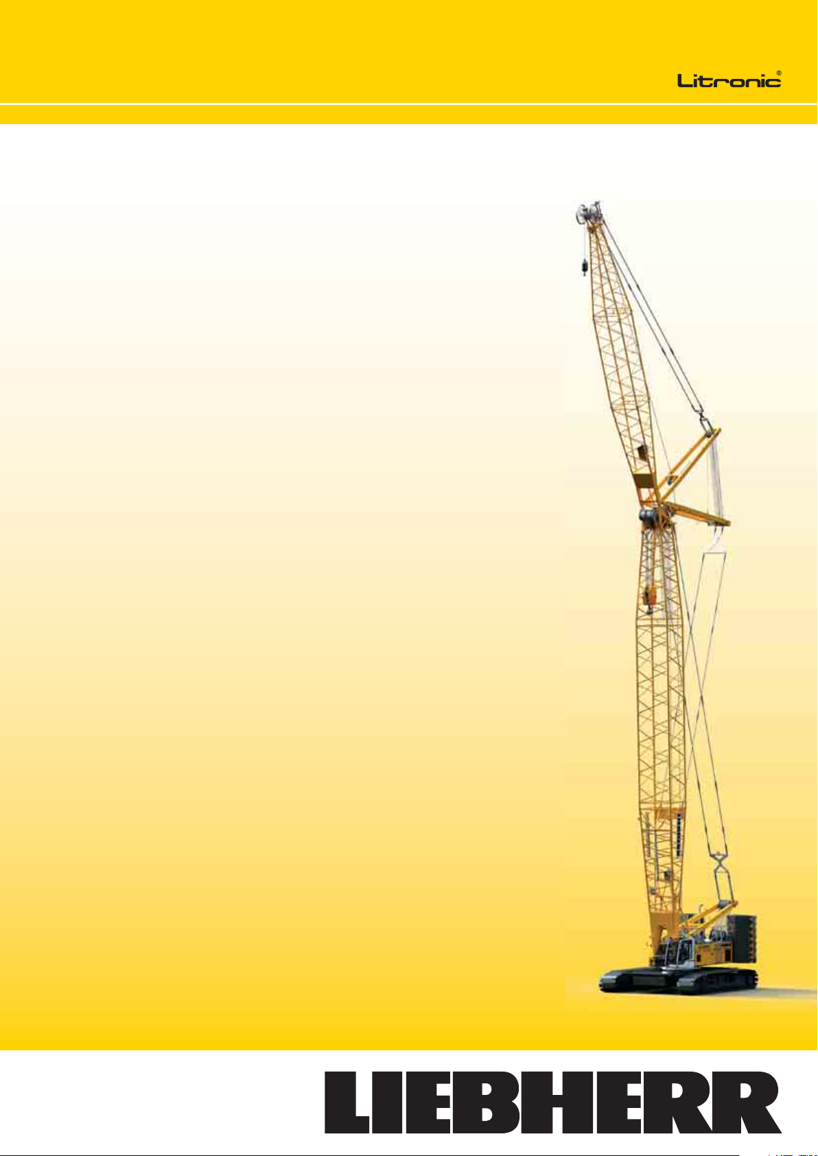
Technical data
Hydraulic lift crane
LR 1250
Page 2
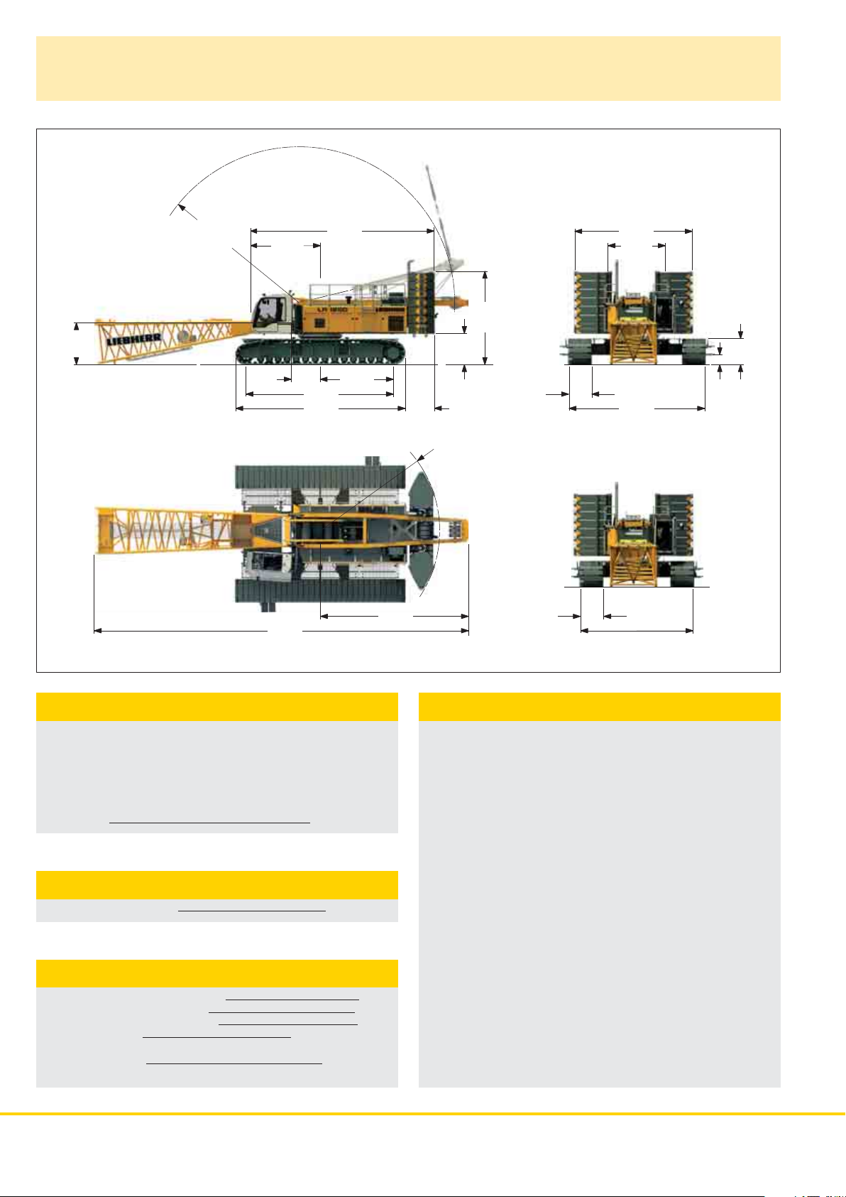
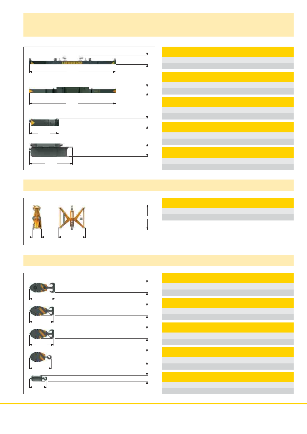
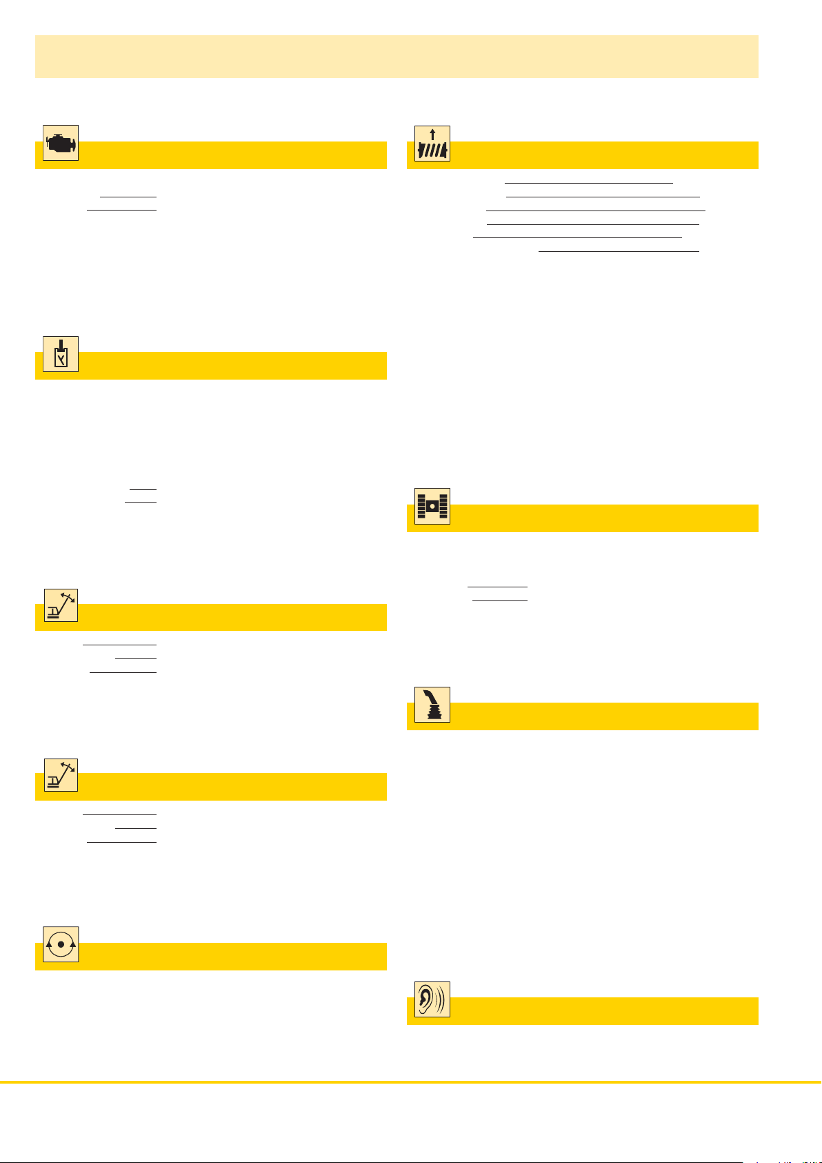
Dimensions
Basic machine with undercarriage
2150
R 8700
3500
19200
1500
7520
8700
9700
3740
7600
1830
R 6200
1600
4600
1200
1200
6050
3000
1345
520
7000
5800
narrow track width
Operating weight
The operating weight includes the basic machine with crawlers,
2 main winches 120 kN including wire ropes (260 m and
495 m) and 20 m main boom, consisting of A-frame, boom
foot (10 m), boom head (7 m) and boom extension (3 m),
82.3 t basic counterweight, 36 t carbody counterweight and
250 t hook block.
Total weight approx. 210 t
Ground pressure
Ground bearing pressure 1.16 kg/cm
2
Equipment
Main boom (No. 2320.xx) max. length 86 m
High reach (No. 2320.x x and 1916.xx) 117 m
Luffing jib (No. 1916.xx) max. length 95 m
Max. combination main boom 53 m
luffing jib 95 m
Fixed jib (No. 1008.xx) 11 m – 26 m
Auxiliary jib 24 t (option 36 t)
Remarks
1. The lifting capacities stated are valid for lifting operation only
(corresponding with crane classification according to F.E.M.
1.0 01. cr ane gr oup A1).
2. Crane standing on firm, horizontal ground.
3. The weight of the lifting device (hoisting ropes, hook block,
shackle etc.) must be deducted form the gross lifting capacity to
obtain a net lifting value.
4. Additional equipment on boom (e.g. boom walkways, auxiliary jib)
must be deducted to get the net lifting capacity.
5. For max. wind speed please refer to lift chart in operator‘s cab
or manual.
6. Working radii are measured from center of swing and under load.
7. The lifting capacities are valid for 360 degrees of swing.
8. Calculation of stability under load is based on DIN 15019 / part 2 /
chart 1 and ISO 4305 Table 1 + 2, tipping angle 4°.
9. The structures are calculated according to F.E.M. 1.001 - 1998
(EN 13001-1; EN 13001-2).
2 LR 1250
Page 3
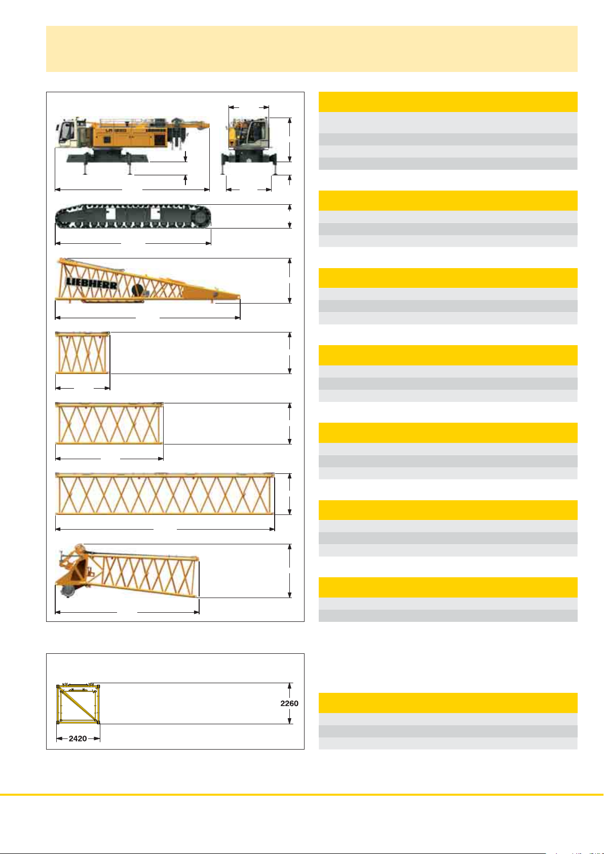
Transport dimensions and weights
Basic machine and main boom (No. 2320.xx)
3150
11575
8700
Option
10300
1400
3000
3300
3220
970
1345
2500
2260
Basic machine
with A-frame, 2x 120 kN crane winches without boom foot, hoist
ropes, basic counterweight and crawlers
Width 3000 mm
Weight 42500 kg
Weight of hoist rope 3.42 kg/m
Crawler 2 x
Track pads 1200 mm
Width 1200 mm
Weight 19800 kg
Boom foot (No. 2320.25)
Width 2430 mm
Weight
incl. winch and rope 5600 kg
without winch 4000 kg
Weight
Boom section (No. 2320.23) 3 m
Width 2430 mm
Weight with HPT
Weight with HPT
1)
830 kg
1)
and NDL2) 920 kg
6150
12150
8050
1) Pendant straps for m ain boom s 2) Pendant s traps fo r jib
Boom transport option
*) Including pendant straps
2260
2260
2950
Boom section (No. 2320.23) 6 m
Width 2430 mm
Weight with HPT
Weight with HPT
1)
1295 kg
1)
and NDL
2)
1455 kg
Boom section (No. 2320.23) 12 m
Width 2430 mm
Weight with HPT
Weight with HPT
1)
2340 kg
1)
and NDL2) 2690 kg
Boom head (No. 2320.23)
Width 2430 mm
Weight with HPT
1)
4300 kg
Boom transport option
(No. 2320.xx /1916.xx) 12/12 6/6 3/3 m
Length 12250 6250 3250 mm
Weight* 3940 2145 1475 kg
LR 1250 3
Page 4
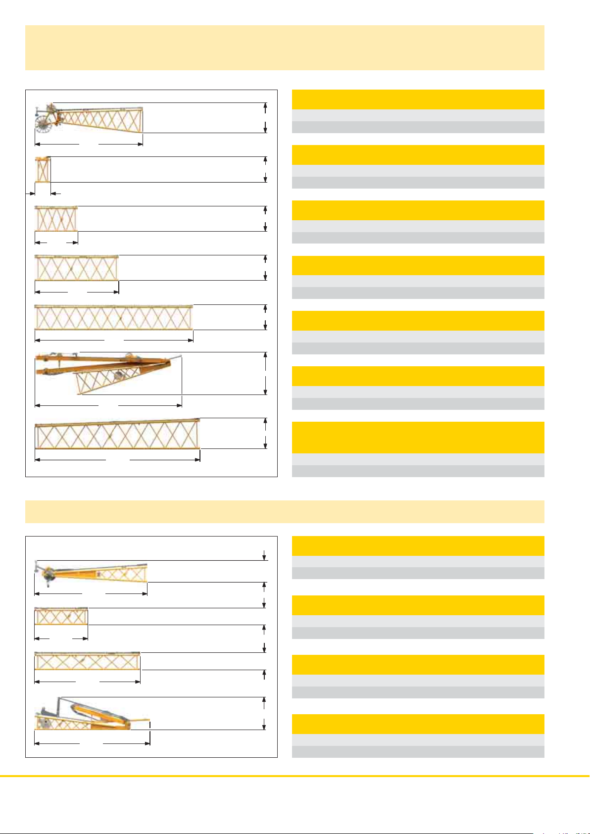
Transport dimensions and weights
Luffing jib (No. 1916.xx)
Luffing jib head (No. 1916.21)
2200
7750
1950
115 0
Width 2010 mm
Weight* 1550 kg
L-boom jib section (No. 1916.22) 1 m
Width 2010 mm
Weight* 460 kg
3150
6150
12150
10850
12220
1850
1850
1850
3150
2300
Luffing jib section (No. 1916.18) 3 m
Width 2010 mm
Weight* 475 kg
Luffing jib section (No. 1916.18) 6 m
Width 2010 mm
Weight* 690 kg
Luffing jib section (No. 1916.18) 12 m
Width 2010 mm
Weight* 1250 kg
Luffing jib foot with A-frames (No. 1916.22)
Width 2010 mm
Weight* 6300 kg
L-boom
section tapered
Width 2430 mm
Weight* 1700 kg
(No. 2320/1916.20) 12 m
Fixed jib (No. 1008.xx)
6500
3120
6120
6620
*) Including pendant straps
1020
1020
1020
1850
Fixed jib head (No. 1008.20)
Width 1090 mm
Weight* 920 kg
Fixed jib section (No. 1008.17) 3 m
Width 1090 mm
Weight* 300 kg
Fixed jib section (No. 1008.17) 6 m
Width 1090 mm
Weight* 455 kg
Fixed jib foot with A-frame (No. 1008.20)
Width 2200 mm
Weight* 1950 kg
4 LR 1250
Page 5
Transport dimensions and weights
Counterweight
Counterweight 1 x
640
6050
400
Width 1660 mm
Weight 12000 kg
Counterweight 1 x
Width 1660 mm
Weight 10000 kg
5790
1905
2800
Mid fall (option)
750
2000
480
825
2060
Counterweight 12 x
Width 1360 mm
Weight 5000 kg
Carbody counterweight 2 x
Width 3340 mm
Weight 9800 kg
Carbody counterweight 2 x
Width 3340 mm
Weight 8300 kg
Mid fall section (No. 1916.xx) 0.5 m
Width 750 mm
Weight 715 kg
Hooks
2230
2100
1800
1600
1100
770
770
770
800
400
250 t hook block - 11 sheaves
Width 1030 1250 mm
Weight 2300 3200 kg
160 t hook block - 7 sheaves
Width 640 760 880 mm
Weight 1500 2250 3000 kg
100 t hook block - 5 sheaves
Width 540 670 770 mm
Weight 1300 1800 2300 kg
40 t hook block - 1 sheave
Width 300 400 500 mm
Weight 700 1100 1500 kg
12.5 t single hook
Width 400 mm
Weight 600 kg
LR 1250 5
Page 6
Technical description
Engine
Power rating according to ISO 9249, 270 kW (362 hp) at 2000 rpm
Engine type
Fuel tank
indicator and reserve warning
Engine complies with NRMM exhaust certification EPA/CARB Tier 4i or
97/68 EC Stage IIIB.
Liebherr D 936 A7 SCR
800 l capacity with continuous level
Hydraulic system
A double axial displacement pump supplies the open loop hydraulic
system, allowing all functions to be operated simultaneously. To
minimize peak pressure an automatic working pressure cut–off is
integrated in the pump.
All filters are electronically monitored.
The use of synthetic environmentally friendly (biodegradable) oils is
possible.
Working pressure
Oil tank capacity
max. 350 bar
650 l
Luffing jib winch
Main winches
Line pull (1st layer) max. 175 kN
Line pull (7th layer)
Rope diameter
Drum diameter
Rope speed
Rope capacity in 7 layers
The winches are outstanding in their compact design and easy
assembly.
Propulsion is via a planetary gearbox in an oil bath.
Load support by the hydraulic system; additional safety factor provided
by a spring loaded, multi–disc holding brake.
The main winches use pressure controlled, variable flow hydraulic
motors. This system features sensors that automatically adjust oil flow
to provide max. winch speed depending on load.
Option – winch with free-fall system:
Clutch and braking functions on the free-fall system are provided by a
compact designed, low wear and maintenance-free multi–disc brake.
120 kN
26 mm
580 mm
0 – 136 m/min
489 m
Crawlers
Propulsion through axial piston motor, hydraulically released spring
loaded multi–disc brake, crawler tracks, hydraulic chain tensioning
device.
Track pads
Drive speed
1200 m m
0 – 1.6 km/h
Line pull max. 105 kN
Rope diameter
Jib luffing
20 mm
51 sec. from 15° to 78°
Boom winch
Line pull max. 217 kN
Rope diameter
Boom up
24 mm
130 sec. from 15° to 86°
Swing
Consists of rollerbearing with external teeth, swing drive with fixed
axial piston hydraulic motor, spring loaded and hydraulically released
multi–disc holding brake, planetary gearbox and pinion.
Both swing modes are possible – speed control or free swing.
A multi– disc holding brake acts automatically at zero swing motion.
Swing speed from 0 – 3 rpm continuously variable.
Control
The hear t of the hydraulic crawler cranes is the Liebherr control system
which has been developed and manufactured in-house.
It includes all control and monitoring functions and is designed to
withstand extreme environmental conditions and heavy duty
construction tasks. Complete machine operating data as well as
warning signals and irregularities are clearly displayed on the high
resolution monitor in the operator‘s cab in the required language.
The electro-hydraulic proportional control allows several movements to
be performed simultaneously. This ensures that all categories of loads
can be positioned with utmost precision.
Option:
s¬ '3-'023¬TELEMATIC S¬MODULE
Noise emission
Noise emissions correspond with 2000/14/EC directive on noise
emission by equipment used outdoors.
6 LR 1250
Page 7
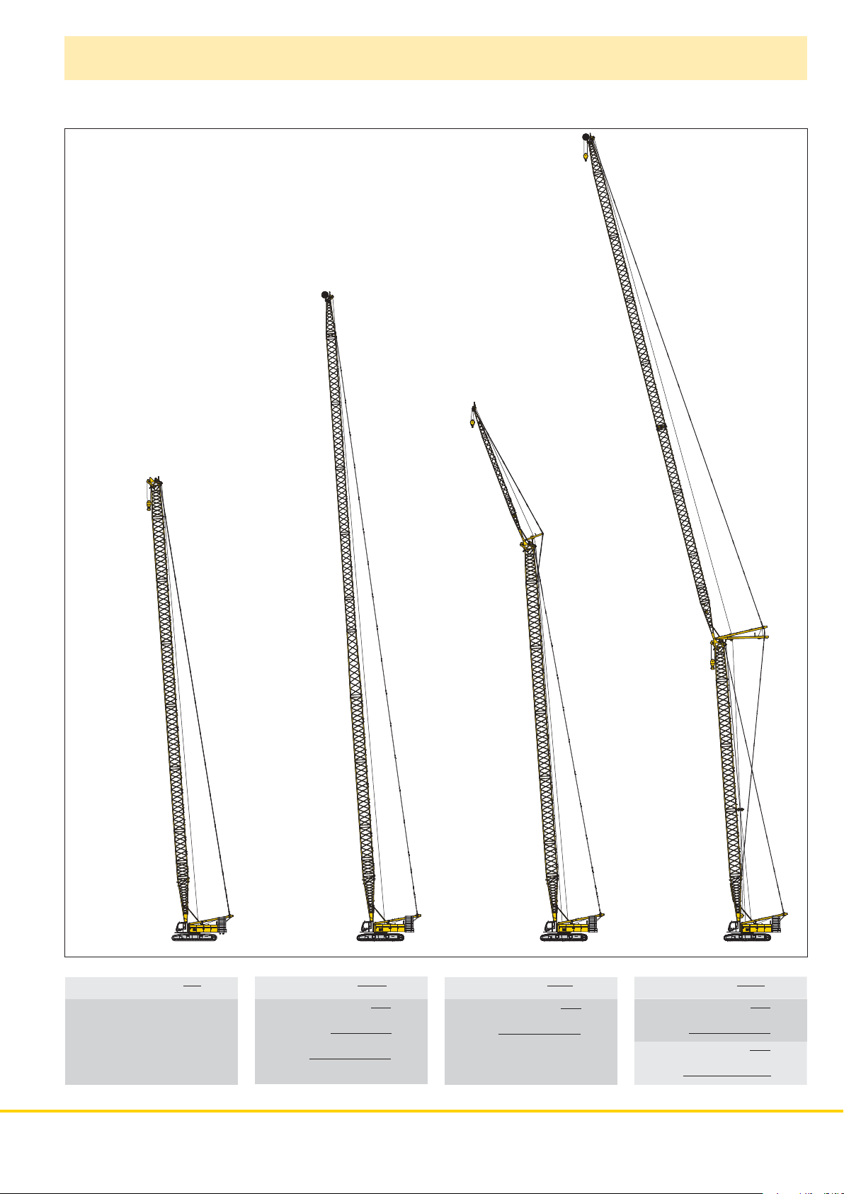
Boom combinations
7.0 m (23 ft)
No. 1916.21
1.0 m (39.4 inch)
No. 1916.22
12.0 m (40 ft)
No. 1916.18
12.0 m (40 ft)
No. 1916.18
7 m (23 ft)
No. 2320.23
12 m (40 ft)
No. 2320.23
12 m (40 ft)
No. 2320.23
12.0 m (40 ft)
No. 1916.18
12.0 m (40 ft)
No. 1916.18
6.0 m (20 ft)
No. 1916.18
5.5 m (18 ft)
No. 1008.20
6.0 m (20 ft)
No. 1008.17
6.0 m (20 ft)
No. 1008.17
3.0 m (10 ft)
No. 1008.17
5.5 m (18 ft)
No. 1008.20
7.0 m (23 ft)
No. 2320.23
12 m (40 ft)
No. 2320.23
7.0 m (23 ft)
No. 1916.21
12.0 m (40 ft)
No. 1916.18
12.0 m (40 ft)
No. 1916.18
12.0 m (40 ft)
No. 1916.18
12.0 m (40 ft)
Mid fall 0.5 m (1.64 ft)
No. 1916.18
No. 1916.32
12.0 m (40 ft)
No. 1916.18
12.0 m (40 ft)
No. 1916.18
6.0 m (20 ft)
No. 1916.18
3.0 m (10 ft)
No. 1916.18
7.0 m (23 ft)
No. 1916.22
12 m (40 ft)
No. 2320.23
12 m (40 ft)
No. 2320.23
12 m (40 ft)
No. 2320.23
6 m (20 ft)
No. 2320.23
3 m (10 ft)
No. 2320.23
10 m (33 ft)
No. 2320.25
Main boom No. 2320.xx 86 m
12.0 m (40 ft)
Tap ere d
No. 2320/1916.20
12 m (40 ft)
No. 2320.23
12 m (40 ft)
No. 2320.23
6.0 m (20 ft)
No. 2320.23
3.0 m (10 ft)
No. 2320.23
10.0 m (33 ft)
No. 2320.25
Max. combination 117 m
Main boom
No. 2320.x x 43 m
Tapered
No. 2320/1916.xx 12 m
Luffing jib
No. 1916.xx 62 m
12 m (40 ft)
No. 2320.23
12 m (40 ft)
No. 2320.23
12 m (40 ft)
No. 2320.23
6 m (20 ft)
No. 2320.23
10.0 m (33 ft)
No. 2320.25
Max. combination 97.0 m
Main boom
No. 2320.x x 71 m
Fixed jib
No. 1008.x x 26 m
7.0 m (23 ft)
No. 2320.23
12 m (40 ft)
No. 2320.23
12 m (40 ft)
No. 2320.23
12 m (40 ft)
No. 2320.23
10.0 m (33 ft)
No. 2320.25
Max. combination 148 m
Main boom
No. 2320.x x 53 m
Luffing jib
No. 1916.xx 95 m
Main boom
No. 2320.xx 56 m
Luffing jib
No. 1916.xx 74 m
LR 1250 7
Page 8
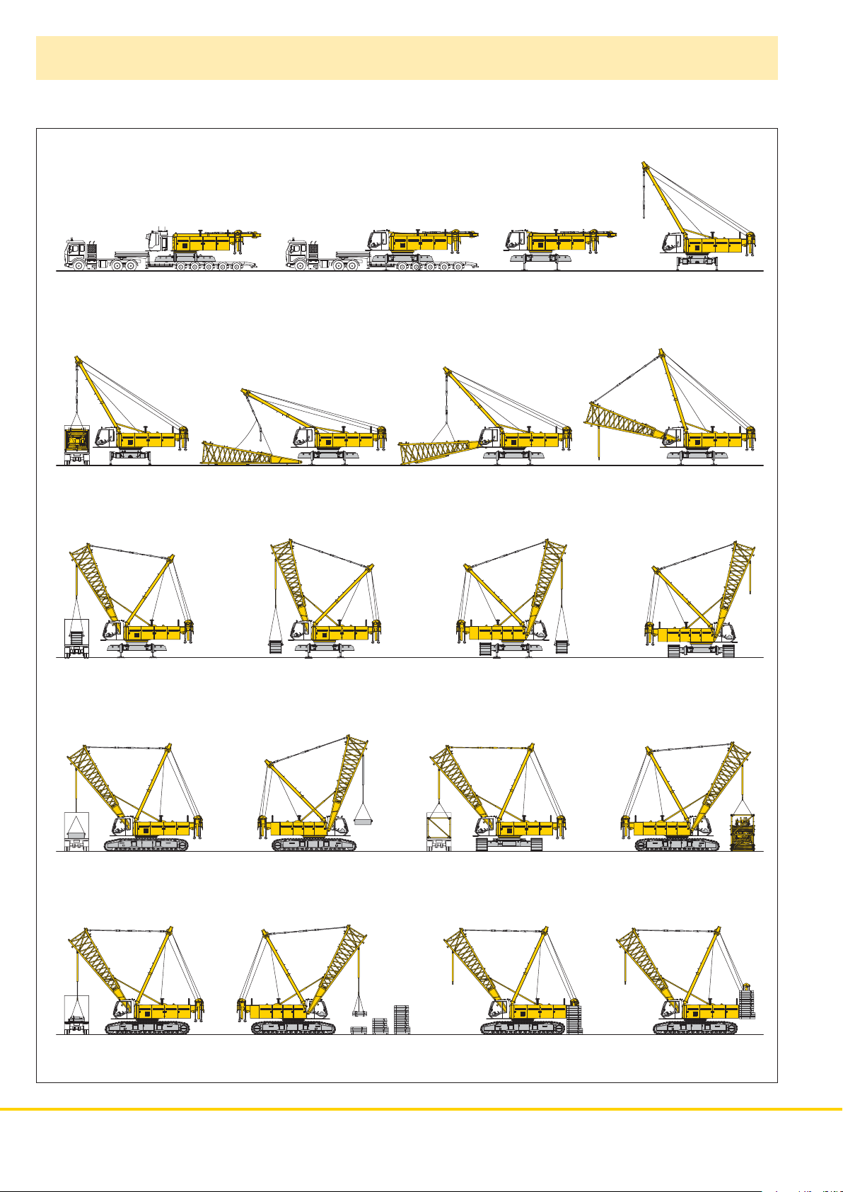
Self assembly system
Unloading of basic machine
Unloading and assembly of boom foot
Unloading and assembly of crawlers
Unloading and assembly of carbody counterweight
Unloading and assembly of boom
Unloading and assembly of counterweight
8 LR 1250
Page 9

Erecting of main boom to working position
Assembly of boom
Reeving of hoist and luffing jib ropes
Erecting of main boom and luffing jib Working position
LR 1250 9
Page 10

Working range - main boom (No. 2320.xx) 86° – 15°
82.3 t counterweight and 36 t carbody counterweight
Auxiliary jib 24 t
2000
86 m
83 m
80 m
77 m
74 m
71 m
68 m
65 m
62 m
59 m
56 m
53 m
50 m
47 m
44 m
41 m
38 m
35 m
32 m
29 m
26 m
23 m
20 m
The maximum capacity of
the auxiliary jib is 24 t.
The corresponding load
chart is programmed in
the LMI system.
Main boom configuration (Table 1 – No. 2320.xx)
Configuration for boom le ngth s (20 m - 86 m)
Length Amount of boom extensions
Boom foot 10 m11111111111111111111111
Boom insert 3 m 1 1 1 1
Boom insert6 m111111111111
Boom insert 12 m 11112222333344445555
Boom head 7 m11111111111111111111111
Boom length (m) 20 23 26 29 32 35 38 41 44 47 50 53 56 59 62 65 68 71 74 77 80 83 86
10 LR 1250
1 1111111
Page 11

Lift chart for main boom (No. 2320.xx)
82.3 t counterweight and 36 t carbody counterweight
Capacities in metric tonnes for boom lengths (20 m - 86 m) – with 120 kN winches
Boom length in (m)
Radius 20 26 32 38 44 50 56 62 68 74 80 86 Radius
(m)tttttttttttt(m)
5.8 122.1 5.8
6 143.5 122.1 6
7 149.9 136.5 117.5 101.4 86.4 72.1 7
8 139.3 132.1 124.2 112.6 96.9 83.4 71.5 59.1 49.8 8
9 128.6 122.4 115.6 109.3 103.6 93.0 80.4 68.1 57.7 49.5 41.3 34.0 9
10 113.8 108.1 102.6 97.5 92.8 88.0 77.1 65.7 56.0 48.1 40.7 33.8 10
12 87.2 87.2 83.5 79.8 76.4 73.1 70.1 61.3 52.9 45.8 39.6 32.7 12
14 70.2 70.2 70.1 67.3 64.7 62.1 59.7 57.3 50.0 43.2 37.6 31.5 14
16 58.5 58.5 58.4 57.9 55.8 53.7 51.7 49.8 47.4 41.3 35.8 30.2 16
18 49.9 49.9 49.7 49.5 48.9 47.1 45.4 43.7 42.1 38.7 34.4 29.2 18
20 43.2 43.3 43.2 42.9 42.6 41.8 40.3 38.8 37.4 36.0 32.4 28.2 20
26 30.2 30.2 29.9 29.7 29.3 28.9 28.4 27.3 26.2 25.2 24.1 26
32 22.5 22.3 22.0 21.7 21.3 20.9 20.5 19.8 19.0 18.0 32
38 17.2 17.0 16.6 16.3 15.9 15.5 15.0 14.6 13.7 38
44 13.4 13.1 12.7 12.3 12.0 11.5 11.1 10.5 44
50 10.4 10.1 9.7 9.3 8.8 8.4 7.9 50
55 8.3 7.9 7.5 7.1 6.6 6.2 55
60 6.4 6.0 5.6 5.2 4.7 60
65 4.8 4.4 4.0 3.5 65
70 3.3 2.9 2.4 70
TAL 10576485 - M00000
Lift chart for main boom (No. 2320.xx)
72.3 t counterweight and 36 t carbody counterweight
Capacities in metric tonnes for boom lengths (20 m - 83 m) – with 120 kN winches
Boom length in (m)
Radius 20 26 32 38 44 50 56 62 68 74 80 83 Radius
(m)tttttttttttt(m)
4,1 250.0* 4,1
5 217.0 196.5 173.7 5
6 185.8 180.1 165.5 143.5 122.1 6
7 162.1 152.0 141.3 131.8 117.5 101.4 86.4 72.1 7
8 138.5 129.3 121.3 114.0 107.5 96.9 83.4 71.5 59.1 49.8 8
9 119.4 112.3 106.1 100.3 95.0 90.1 80.4 68.1 57.7 49.5 41.3 37.2 9
10 104.4 99.2 94.1 89.3 85.0 80.9 77.1 65.7 56.0 48.1 40.7 36.9 10
12 79.9 79.8 76.5 73.1 69.9 66.9 64.0 61.3 52.9 45.8 39.6 35.7 12
14 64.3 64.2 64.1 61.5 59.0 56.6 54.4 52.2 50.0 43.2 37.6 34.3 14
16 53.4 53.4 53.3 52.9 50.9 48.9 47.0 45.2 43.5 41.3 35.8 32.7 16
18 45.5 45.5 45.4 45.1 44.5 42.8 41.2 39.6 38.1 36.6 34.4 31.5 18
20 39.3 39.4 39.3 39.0 38.7 37.9 36.5 35.1 33.8 32.4 31.2 30.0 20
26 27.4 27.4 27.1 26.8 26.4 26.1 25.5 24.4 23.4 22.4 21.9 26
32 20.3 20.1 19.8 19.4 19.0 18.6 18.2 17.5 16.7 16.2 32
38 15.3 15.1 14.8 14.4 14.0 13.6 13.1 12.5 12.1 38
44 11.8 11.5 11.2 10.8 10.4 9.9 9.5 9.2 44
50 9.0 8.7 8.3 7.9 7.4 7.0 6.8 50
55 7.0 6.6 6.3 5.8 5.4 5.2 55
60 5.3 4.9 4.5 4.0 3.8 60
65 3.7 3.3 2.9 2.7 65
70 2.3 70
Above lift chart is for reference only. For actual lift duty please refer to lift chart in operator‘s cab or manual.
*) Capacities over 220 t require a special heavy duty boom head.
TAL 10576485 - M00000
LR 1250 11
Page 12

L-boom high reach (No. 2320/1916.xx) 66 m – 117 m
Working range 86° – 15°
4
L-boom configuration with 43 m main boom (No. 2320.xx/1916.xx)
Configuration for L-boom l engt hs (60.5 m - 92 .6 m)
Length Amount of boom and luffing jib extensions
Boom foot 10 m 111111111111111111
Boom insert 3 m 111111111111111111
Boom insert 6 m 111111111111111111
Boom insert 12 m 222222222222222222
Tapered 12 m 111111111111111111
Luffing insert3 m111111111
Luffing insert6 m111111111
Luffing insert 12 m 111122223333444
Luffing jib head 8 m 111111111111111111
Ma x. L-b oom l e n gth (m) 66 6 9 72 75 78 81 8 4 87 9 0 9 3 9 6 9 9 1 02 10 5 10 8 111 114 117
12 LR 1250
Page 13

Lift chart for L-boom (No. 2320/1916.xx)
Main boom length 43 m Main boom length 55 m
Capacities in metric tonnes
82.3 t counterweight and 36 t carbody counterweight
Boom length in (m)
Radius 66 75 90 99 108 117
(m) tttttt
8.9 60.9
10 58.7 39.5
12 51.2 37.0 23.2
14 44.8 34.4 21.5 15.8 12.1
16 39.5 32.0 19.9 14.6 11.4 8.8
18 35.3 30.0 18.6 13.7 10.6 8.1
20 31.8 27.7 17.3 12.7 10.0 7.6
22 29.2 25.5 16.5 11.9 9.3 7.2
24 26.6 23.8 15.5 11.3 8.7 6.7
26 24.5 22.0 14.7 10.7 8.3 6.4
28 22.9 20.4 14.1 10.2 7.9 6.1
30 21.0 19.1 13.5 9.8 7.6 5.8
32 19.5 17.9 12.9 9.5 7.3 5.5
34 18.3 16.8 12.4 9.1 7.1 5.3
36 17.2 15.8 12.1 8.7 6.8 5.1
38 16.3 15.0 11.7 8.4 6.5 4.9
40 15.5 14.2 11.2 8.2 6.3 4.7
42 14.8 13.4 10.8 7.9 6.1 4.5
44 14.0 12.7 10.5 7.6 5.9 4.4
46 13.2 12.1 10.2 7.3 5.7 4.2
48 12.5 11.5 9.8 7.1 5.4 4.1
50 11.7 11.0 9.3 6.9 5.3 3.9
55 10.0 9.7 8.4 6.3 4.9 3.6
60 8.5 8.5 7.5 5.7 4.4 3.3
65 7.3 7.3 6.5 5.2 4.0 2.9
70 6.3 5.7 4.7 3.6 2.6
80 4.2 3.7 3.0 2.0
85 3.5 3.1 2.6
90 2.7 2.1
95 2.2
TLT 10576485 - M00000
Above lif t chart is for reference only. For actual lif t duty please refer to lift chart in operator‘s cab or manual.
Capacities in metric tonnes
82.3 t counterweight and 36 t carbody counterweight
Boom length in (m)
Radius 78 90 96 102 108 114
(m) tttttt
10.2 43.8
12 43.0 28.3
14 40.7 26.6 23.3 19.0 15.3
16 37.7 24.9 21.8 17.7 14.4 12.0
18 33.2 23.5 20.7 16.6 13.4 11.2
20 30.0 22.1 19.4 15.7 12.7 10.5
22 26.8 21.1 18.4 14.7 11.9 10.0
24 24.4 19.9 17.6 14.0 11.2 9.4
26 22.5 18.9 16.8 13.4 10.7 9.0
28 20.5 18.2 16.1 12.8 10.2 8.6
30 18.8 17.1 15.6 12.3 9.8 8.2
32 17.6 15.7 14.8 11.9 9.5 7.9
34 16.2 14.5 13.7 11.5 9.2 7.6
36 15.0 13.6 12.8 11.0 8.8 7.4
38 14.0 12.7 12.0 10.6 8.5 7.1
40 13.2 11.8 11.3 10.3 8.2 6.9
42 12.5 10.9 10.5 10.1 8.0 6.7
44 11.9 10.2 9.8 9.4 7.8 6.5
46 11.3 9.7 9.1 8.7 7.3 6.3
48 10.9 9.2 8.6 8.1 6.9 6.0
50 10.5 8.7 8.1 7.6 6.5 5.7
55 9.0 7.8 7.2 6.7 5.8 5.1
60 7.7 6.9 6.4 5.9 5.1 4.6
65 6.5 5.8 5.6 5.3 4.5 4.0
70 5.4 5.0 4.7 4.5 4.0 3.5
75 4.5 4.3 4.0 3.7 3.2 3.0
80 3.6 3.3 3.1 2.6 2.3
85 2.9 2.8 2.6 2.1
90 2.1 2.1
TLT 10576485 - M00000
L-boom configuration with 55 m main boom (No. 2320.xx/1916.xx)
Configuration for L-boom l engt hs (72 .5 m - 92 .9 m)
Length Amount of boom and luffing jib extensions
Boom foot 10 m1111111111111
Boom insert 3 m1111111111111
Boom insert 6 m1111111111111
Boom insert 12 m3333333333333
Tapered 12 m1111111111111
Luffing insert3 m1111111
Luffing insert6 m111111
Luffing insert 12 m 1111222233
Luffing jib head 8 m1111111111111
Ma x. L-b oom l e n gth (m) 78 8 1 8 4 87 90 93 9 6 9 9 10 2 1 05 108 111 114
LR 1250 13
Page 14

Working range - luffing jib (No. 1916.xx) 78° – 15°
Main boom 88° – 45°
95 m
92 m
89 m
86 m
83 m
80 m
77 m
74 m
71 m
68 m
65 m
62 m
59 m
56 m
53 m
50 m
47 m
44 m
41 m
38 m
35 m
32 m
29 m
26 m
23 m
20 m
59 m
56 m
53 m
50 m
47 m
44 m
41 m
38 m
35 m
32 m
29 m
26 m
23 m
Boom configuration for main boom lengths
Jib configuration for jib lengths
Length Amount of luffing jib extensions
Luffing jib foot 7 m 11111111111111111111111111
Luffing jib insert 3 m 1111111111111
Luffing jib insert6 m11111111111111
Luffing jib insert 12 m 1 1122223333444455556666
Luffing jib head 7 m 11111111111111111111111111
Luffing jib length (m) 20 23 26 29 32 35 38 41 44 47 50 53 56 59 62 65 68 71 74 77 80 83 86 89 92 95
(20 m – 95 m)
(23 m – 59 m) –
see table 1 on page
10
14 LR 1250
Page 15

Lift chart - luffing jib (No.1916.xx)
Main boom 88°
Main boom 23 m Main boom 35 m
Radius (m) t t t t t t t t
20 29 41 53 62 71 83 95
7.9 70.7
10 70.7 61.8
13 63.5 54.0 38.2
15 53.4 48.4 35.4 25.8
17 45.7 43.0 32.5 24.8 18.2
19 38.4 37.1 30.1 23.7 17.6 13.0
22 30.8 30.0 26.4 22.1 16.5 12.5 8.4
24 26.9 24.3 20.9 15.9 12.2 8.2 5.0
28 22.2 20.4 18.8 14.8 11.6 7.9 5.0
30 20.6 18.9 17.7 14.3 11.4 7.8 4.9
38 14.5 13.4 11.8 10.3 7.2 4.7
42 12.9 11.9 10.6 9.4 6.9 4.4
50 9.6 8.4 7.9 6.0 4.0
60 6.5 5.9 4.8 3.2
70 4.4 3.6 2.4
80 2.5
Main boom 44 m Main boom 53 m
20 29 41 53 62 71 83 95
Radius (m) t t t t t t t t
8.7 57.8
11 54.9 44.0
13 49.7 42.5 30.4
16 40.8 37.3 28.7 19.8
18 35.9 33.3 27.0 19.4 14.1
20 31.5 29.3 25.2 19.0 13.9 10.3
22 28.1 26.0 22.9 18.5 13.7 10.1 6.6
26 21.6 19.4 16.9 13.4 9.9 6.5 3.9
32 17.6 15.7 14.4 12.5 9.7 6.5 3.9
40 12.6 11.5 10.2 8.9 6.2 3.8
44 11.2 10.3 9.2 8.0 6.1 3.8
55 8.0 6.9 6.1 4.9 3.3
60 6.2 5.3 4.4 3.0
70 4.1 3.2 2.2
75 2.7
80 2.2
Jib length in (m)
20 29 41 53 62 71 83 95
Rdaius (m) t t t t t t t t
8.3 69.2
11 66.0 51.6
13 57.8 49.1 34.4
16 45.8 42.5 31.7 22.6
18 39.6 38.1 29.7 21.9 15.8
19 36.8 35.3 28.8 21.6 15.6 11.5
22 30.4 28.9 25.6 20.3 15.0 11.2 7.4
24 26.1 23.9 19.5 14.6 11.0 7.3 4.4
32 12.1 17.5 16.0 13.4 10.4 7.1 4.3
42 13.1 12.0 10.6 9.1 6.6 4.1
50 9.8 8.6 7.9 6.0 3.8
55 8.0 7.6 6.9 5.6 3.5
60 6.8 6.0 5.0 3.2
70 4.6 3.7 2.4
75 3.2 2.0
80 2.6
Jib length in (m)
20 29 41 53 62 71 83 95
Radius (m) t t t t t t t t
9 46.6
11 44.1 35.7
14 39.9 33.3 24.6
16 35.3 31.2 23.8 16.9
18 31.6 28.8 22.8 16.5 12.4
20 27.9 26.0 21.7 16.0 12.2 9.1
24 12.1 21.3 18.8 15.0 11.7 8.8 5.8
26 19.6 17.4 14.3 11.6 8.8 5.8 3.3
32 16.2 14.3 12.4 10.8 8.6 5.8 3.3
40 11.5 10.0 9.0 8.1 5.7 3.3
44 10.4 9.0 8.1 7.2 5.7 3.3
55 7.0 6.1 5.4 4.3 2.8
60 5.5 4.7 3.7 2.4
65 4.1 3.1 2.1
70 3.6 2.6
75 2.2
Jib length in (m)
Jib length in (m)
Main boom 56 m Main boom 59 m
Radius (m) t t t t t t t t
20 29 35 41 53 62 71 74
9.1 43.1
11 41.3 32.6
13 38.8 31.5 27.1
14 37.7 30.7 26.4 22.8
16 33.8 29.0 25.3 21.9 15.7
18 30.5 27.2 24.0 21.0 15.3 11.9
20 27.0 24.7 22.4 20.1 14.8 11.7 8.7
22 24.4 22.2 21.0 18.8 14.3 11.4 8.6 7.8
24 12.1 20.4 19.0 17.9 13.8 11.1 8.4 7.7
32 15.6 14.4 13.7 11.9 10.3 8.2 7.6
38 12.4 11.6 10.1 9.1 8.0 7.4
44 10.0 8.6 7.9 6.8 6.6
55 6.7 5.9 5.1 4.9
60 5.3 4.4 4.2
70 3.4 3.2
75 2.7
Capacities in metric tonnes with luffing jib (No. 1916.xx), 82.3 counter weight + 36 t carbody counterweight. Above lift chart is for reference only.
For actual lift duty and complete chart with all available configurations please refer to lift chart in operator‘s cab or manual.
Jib length in (m)
20 29 35 41 50
Radius (m) t t t t t
9.2 39.1
12 36.7 29.4
13 35.7 28.8 24.8
14 34.9 28.0 24.2 20.9
16 31.8 26.8 23.3 20.1 16.0
18 29.0 25.5 22.3 19.3 15.4
20 25.8 23.5 21.0 18.6 14.8
22 23.4 21.2 20.0 17.6 14.3
24 12.1 19.5 18.2 16.9 13.8
32 15.0 13.8 13.1 11.7
36 12.5 11.7 10.5
38 11.9 11.1 10.0
42 10.2 9.0
44 9.7 8.6
48 7.9
50 7.6
Jib length in (m)
TLT 10576485 - M00000
LR 1250 15
Page 16

Lift chart - luffing jib (No. 1916.xx)
Main boom 83°
Main boom 23 m Main boom 35 m
Radius (m) t t t t t t t t
20 29 44 53 62 71 83 95
11.7 70.7
15 63.6 53.8
19 46.2 43.9 29.5
22 37.1 36.3 26.8 22.8
24 32.1 32.5 25.0 21.8 16.1
28 26.2 22.1 20.4 15.4 11.9
32 22.1 19.3 19.0 14.6 11.4 7.9
34 18.2 17.9 14.4 11.2 7.8 4.9
42 14.4 14.4 12.2 10.1 7.1 4.6
48 10.8 11.9 10.7 9.1 6.6 4.2
50 11.3 10.2 8.9 6.4 4.2
55 9.7 9.0 8.0 6.1 3.8
65 6.6 6.5 5.0 3.2
70 5.5 4.5 2.7
75 4.0 2.3
85 2.7
Main boom 44 m Main boom 53 m
20 29 41 53 62 71 83 95
Radius (m) t t t t t t t t
14.2 51.6
17 47.4 39.6
22 36.9 34.6 26.3
24 32.2 31.1 25.1 18.3
26 29.2 28.4 23.8 18.1
28 26.0 22.8 18.0 13.3
30 23.8 21.4 17.7 13.3 9.8
34 20.6 19.4 17.0 12.9 9.8 6.5
36 12.1 18.1 16.3 12.7 9.7 6.5
38 16.9 15.6 12.6 9.6 6.5 3.9
46 13.3 12.9 11.6 9.0 6.2 3.8
55 10.1 9.2 8.0 5.7 3.6
65 7.1 6.5 5.0 3.0
75 4.9 4.3 2.4
80 3.7 2.2
85 3.0
Jib length in (m)
20 29 41 53 62 71 83 95
Radius (m) t t t t t t t t
13.1 64.5
16 54.6 47.5
20 44.0 41.8 30.1
24 34.0 33.9 26.8 20.3
26 30.1 30.7 25.5 19.8 14.6
28 27.8 24.2 19.4 14.4 10.9
32 23.5 22.0 18.6 13.9 10.8 7.2
34 21.7 20.8 18.1 13.6 10.7 7.2
36 19.4 17.6 13.4 10.5 7.1 4.3
38 18.2 17.1 13.1 10.3 7.1 4.3
46 14.1 13.9 12.2 9.5 6.6 4.1
55 10.8 9.8 8.5 6.0 3.7
65 7.5 7.2 5.4 3.1
75 5.3 4.8 2.5
80 4.1 2.2
85 3.3
Jib length in (m)
20 29 41 53 62 71 83 95
Radius (m) t t t t t t t t
15.3 40.3
18 37.6 31.5
22 33.3 28.8 22.5
26 27.0 25.4 21.1 15.6
28 24.7 23.8 20.4 15.5 11.7
32 20.4 18.4 15.1 11.6 8.8
34 19.2 17.5 14.9 11.6 8.8 5.8
36 18.0 16.6 14.3 11.5 8.7 5.8
38 15.6 13.6 11.4 8.7 5.8 3.3
42 13.8 12.5 10.8 8.7 5.7 3.3
48 11.8 10.6 9.9 8.2 5.7 3.3
55 9.0 8.2 7.6 5.3 3.3
60 7.5 7.2 6.6 5.1 3.0
65 6.4 5.8 4.6 2.8
75 4.4 3.6 2.2
85 2.6
Jib length in (m)
Jib length in (m)
Main boom 56 m Main boom 59 m
Radius (m) t t t t t t t t
20 29 35 41 53 62 71 74
15.7 37.4
19 34.6 29.0
22 31.7 27.0 23.9 20.8
26 26.4 24.2 22.1 19.8 14.6
28 24.3 23.0 21.0 19.3 14.6 11.2
32 19.7 18.9 17.7 14.2 11.2 8.3 7.6
36 17.4 16.5 16.1 13.6 11.1 8.3 7.6
40 14.7 14.2 12.5 10.9 8.3 7.6
42 13.9 13.4 12.0 10.5 8.3 7.6
46 12.1 10.8 9.8 8.1 7.5
48 11.4 10.2 9.6 7.9 7.4
55 8.6 8.0 7.3 7.0
60 7.6 7.0 6.3 6.2
65 6.3 5.5 5.4
75 4.2 4.1
80 3.5
Capacities in metric tonnes with luffing jib (No. 1916.xx), 82.3 counter weight + 36 t carbody counterweight. Above lift chart is for reference only.
For actual lift duty and complete chart with all available configurations please refer to lift chart in operator‘s cab or manual.
16 LR 1250
Jib length in (m)
20 29 35 41 50
Radius (m) t t t t t
16 34.4
19 32.1 26.9
22 29.6 25.1 22.2
24 27.5 24.2 21.3 18.8
26 25.4 23.0 20.7 18.4 14.6
28 23.5 22.0 19.8 18.0 14.5
32 19.0 18.1 16.7 14.2
36 16.8 15.9 15.4 13.4
38 12.1 15.0 14.4 12.8
40 14.2 13.6 12.3
42 13.4 12.8 11.8
44 12.2 11.2
46 11.6 10.6
48 11.0 10.0
50 9.6
55 8.6
Jib length in (m)
TLT 10576485 - M00000
Page 17

Lift chart - luffing jib (No. 1916.xx)
Main boom 75°
Main boom 23 m Main boom 35 m
Radius (m) t t t t t t t t
20 29 41 53 62 71 83 95
18 50.5
22 39.8 39.2
28 12.1 29.3 26.7
32 24.9 23.8 20.3
36 21.5 21.1 19.5 14.5
40 18.3 17.7 13.9 10.8
44 16.3 15.8 13.2 10.4 7.0
48 14.3 14.1 12.6 10.0 6.8
50 13.3 12.1 9.8 6.7 4.3
55 11.7 10.7 9.3 6.4 4.0
60 9.6 9.6 8.3 6.1 3.7
65 8.3 7.5 5.7 3.4
70 6.7 5.1 3.1
75 5.9 4.7 2.8
80 4.3 2.5
85 3.8 2.2
Main boom 44 m Main boom 53 m
20 29 41 53 62 71 83 95
Radius (m) t t t t t t t t
24 31.0
28 26.6 25.2
32 22.9 22.0 20.6
38 18.2 17.1 15.9
42 16.0 15.4 14.2 12.7
46 13.8 12.8 12.0 9.4
48 13.0 12.1 11.4 9.3
50 12.3 11.6 10.9 9.2 6.2
55 10.3 9.6 8.8 6.0 3.7
60 9.0 8.6 7.8 5.8 3.5
65 8.0 7.6 6.9 5.6 3.3
70 6.8 6.1 5.2 3.1
75 5.5 4.6 2.9
80 4.9 4.0 2.6
85 3.5 2.4
90 3.1 2.2
Jib length in (m)
20 29 41 53 62 71 83 95
Radius (m) t t t t t t t t
22 36.9
26 30.9 29.8
30 25.9 25.6 24.2
36 20.4 19.9 18.6
40 12.1 17.4 16.6 13.4
44 15.4 14.8 13.0 10.1
48 13.7 13.2 12.6 9.8 6.6
50 13.0 12.5 12.1 9.6 6.5
55 11.0 10.6 9.3 6.2 3.9
60 9.7 9.3 8.8 6.0 3.6
65 8.2 7.7 5.8 3.4
70 7.3 6.8 5.6 3.1
75 6.0 5.4 2.9
80 5.3 4.8 2.6
85 4.2 2.4
90 3.7 2.2
Jib length in (m)
20 29 41 53 62 71 83 95
Radius (m) t t t t t t t t
25.2 26.7
30 22.5 21.3
34 19.8 18.7 17.3
36 12.1 17.6 16.3
40 15.8 14.6 13.4
44 14.2 13.1 12.0 11.2
48 11.9 10.8 10.1 8.7
50 11.3 10.3 9.6 8.6
55 10.1 9.1 8.4 7.6 5.6
60 8.1 7.5 6.7 5.5 3.1
65 7.3 6.6 5.9 4.9 3.1
70 5.9 5.2 4.3 2.9
75 5.3 4.6 3.7 2.7
80 4.0 3.2 2.3
85 3.5 2.7
90 2.3
Jib length in (m)
Jib length in (m)
Main boom 56 m Main boom 59 m
Radius (m) t t t t t t t t
20 29 35 41 53 62 71 74
26 25.0
30 21.7 20.5
34 19.1 18.0 17.3
36 18.0 17.0 16.3 15.7
40 15.2 14.5 14.0 12.8
44 13.7 13.1 12.6 11.5 10.7
46 12.4 11.9 10.9 10.1
48 11.9 11.4 10.3 9.6 8.3
50 11.3 10.8 9.8 9.1 8.2 7.5
55 9.7 8.7 8.0 7.2 7.0
60 7.7 7.1 6.3 6.1
65 6.9 6.3 5.5 5.4
70 5.6 4.8 4.7
75 5.0 4.2 4.1
80 3.7 3.6
85 3.3 3.1
Capacities in metric tonnes with luffing jib (No. 1916.xx), 82.3 counter weight + 36 t carbody counterweight. Above lift chart is for reference only.
For actual lift duty and complete chart with all available configurations please refer to lift chart in operator‘s cab or manual.
Jib length in (m)
20 29 35 41 50
Radius (m) t t t t t
26.7 23.4
28 22.4
30 20.9
32 19.6 18.5
34 18.4 17.3 16.6
36 17.3 16.3 15.6 15.0
38 15.4 14.8 14.2
40 14.6 14.0 13.4 12.6
42 13.8 13.2 12.7 11.9
44 13.1 12.5 12.0 11.3
46 12.1 11.9 11.4 10.7
48 11.4 10.9 10.2
50 10.9 10.4 9.7
55 9.2 8.6
60 7.6
65 6.8
Jib length in (m)
TLT 10576485 - M00000
LR 1250 17
Page 18

Lift chart - luffing jib (No. 1916.xx)
Main boom 65°
Main boom 23 m Main boom 35 m
Radius (m) t t t t t t t t
20 29 41 53 62 71 83 95
26 30.7
30 25.7 25.4
32 12.1 23.4
38 18.9 18.4
40 17.7 17.3
44 15.3 14.7
48 13.6 13.1
50 12.9 12.4 12.0
55 10.8 10.4 9.6
60 9.5 9.2 8.7
65 8.1 7.6 6.0
70 7.2 6.7 5.7 3.2
75 6.0 5.4 3.0
80 5.3 4.7 2.7
85 4.1 2.4
90 3.6 2.2
Main boom 44 m Main boom 53 m
20 29 41 53 62 71 83
Radius (m) t t t t t t t
33 19.2
38 16.1
40 15.0 14.6
46 12.1 11.5
48 11.5 10.9
55 9.0 8.2
60 7.9 7.3 6.6
65 6.4 5.8 5.1
70 5.6 5.2 4.4 3.5
75 4.6 3.8 3.0
80 4.0 3.3 2.5
85 2.9 2.0
90 2.5
Jib length in (m)
20 29 41 53 62 71 83 95
Radius (m) t t t t t t t t
29.2 24.0
34 20.2
36 18.8 18.4
40 16.1
42 15.1 14.5
44 14.2 13.6
50 11.5 10.9
55 10.1 9.5 9.1
60 8.3 7.9 7.3
65 7.4 7.0 6.4
70 6.1 5.6 4.8
75 5.4 4.9 4.2 3.0
80 4.3 3.6 2.8
85 3.8 3.1 2.3
90 2.7
95 2.3
Jib length in (m)
20 29 41 53 62 71
Radius (m) t t t t t t
36.8 14.7
40 13.4
42 12.7 11.8
44 11.9 11.2
48 10.1
50 9.6 8.5
55 7.5
60 6.7 5.7
65 5.9 5.0 4.4
70 4.4 3.8 3.0
75 3.9 3.3 2.5
80 2.8 2.1
85 2.4
Jib length in (m)
Jib length in (m)
Main boom 56 m Main boom 59 m
Radius (m) t t t t t t t t
20 29 35 41 53 62 71 74
38.1 13.3
44 11.3 10.4
46 10.7 9.9
48 9.4 8.8
55 7.4 6.9
60 6.6 6.1 5.2
65 5.4 4.5 3.9
70 3.9 3.3 2.5 2.4
75 3.4 2.8 2.1
80 2.4
85 2.0
Capacities in metric tonnes with luffing jib (No. 1916.xx), 82.3 counter weight + 36 t carbody counterweight. Above lift chart is for reference only.
For actual lift duty and complete chart with all available configurations please refer to lift chart in operator‘s cab or manual.
18 LR 1250
Jib length in (m)
20 29 35 41 50
Radius (m) t t t t t
39.4 12.0
42 11.2
44 10.6
46 10.0 9.2
48 8.7 8.1
50 8.3 7.7
55 7.3 6.8 6.3
60 6.0 5.6 4.9
65 4.9 4.3
70 3.7
75 3.3
Jib length in (m)
TLT 10576485 - M00000
Page 19

Lift chart - luffing jib (No. 1916.xx)
Main boom 45°
Main boom 23 m Main boom 35 m
Radius (m) t t t t t t t
20 29 41 53 62 71 83
35.4 18.9
38 17.2
44 13.9
46 13.1
55 9.9
65 7.2
70 6.3 5.9
75 5.2
80 4.1
85 3.6
90 2.5
95 2.1
Main boom 44 m Main boom 53 m
20 29 41 53
Radius (m) t t t t
50.2 8.0
60 5.7
70 3.7
80 2.1
Jib length in (m)
20 29 41 53 62
Radius (m) t t t t t
43.8 11.9
46 11.2
55 8.3
65 5.9
75 4.0
80 3.0
85 2.6
Jib length in (m)
20 29
Radius (m) t t
56.6 4.9
65 3.3
Jib length in (m)
Jib length in (m)
Main boom 56 m Main boom 59 m
20 29
Radius (m) t t
58.7 3.9
60 3.8
70 2.1
Capacities in metric tonnes with luffing jib (No. 1916.xx), 82.3 counter weight + 36 t carbody counterweight. Above lift chart is for reference only.
For actual lift duty and complete chart with all available configurations please refer to lift chart in operator‘s cab or manual.
Jib length in (m)
20
Radius (m) t
60.8 2.9
Jib length in (m)
TLT 10576485 - M00000
LR 1250 19
Page 20

Working range - fixed jib (No. 1008.xx) 15° and 30°
Main boom 88° – 30°
Boom configuration for boom lengths (20 m – 77 m) – see table 1 on page 10
Fixed jib configuration for fixed jib lengths (11 m – 26 m)
Length Amount of fixed jib extensions
Fixed jib foot 5.5 m111111
Fixed jib insert 3 m 1 1 1
Fixed jib insert 6 m 1 1 2 2
Fixed jib head 5.5 m111111
Fixed jib length (m) 11 14 17 20 23 26
20 LR 1250
Page 21

Lift chart - fixed jib (No. 1008.xx)
Offset 15°
Main boom 20 m Main boom 29 m Main boom 38 m
Fixed jib length in (m)
Radius 11 14 20 26
(m) t t t t
9 35.9 35.5
11 35.9 34.0 28.9
12 35.9 33.2 27.7 19.8
14 35.9 31.5 25.5 18.3
16 35.1 29.9 23.9 17.1
20 32.8 26.5 20.0 15.1
24 27.5 23.2 17.0 13.4
28 24.0 20.7 14.8 11.7
30 23.0 19.5 13.8 11.1
32 18.4 13.0 10.5
38 11.3 9.0
44 7.9
Radius 11 14 20 26
(m) tttt
8 35.9 35.9
10 35.9 35.2 30.2
12 35.9 34.2 28.5 19.7
16 35.9 32.0 25.0 17.3
20 34.7 29.9 21.9 15.4
28 27.6 24.6 17.1 13.0
32 23.0 21.8 15.3 11.6
36 19.3 19.7 13.7 10.6
38 17.8 18.2 13.2 10.1
40 16.8 12.7 9.7
46 11.4 8.7
50 8.1
Main boom 47 m Main boom 56 m Main boom 62 m
Fixed jib length in (m)
Radius 11 14 20 26
(m) t t t t
6.6 35.9
8 35.9 35.8
11 35.9 34.5 28.3
13 35.9 33.7 26.9 18.5
16 35.9 32.6 25.1 17.1
20 34.8 31.1 22.9 15.7
28 26.4 26.8 19.8 13.7
36 18.1 18.4 16.8 12.3
50 10.2 10.5 11.0 9.7
55 8.7 9.1 9.0
60 7.6 8.0
65 6.7
Radius 11 14 20 26
(m) tttt
6.9 35.9
9 35.9 34.5
11 35.9 33.7 26.6
13 35.9 32.8 25.5 17.8
20 34.3 29.9 22.0 15.5
28 25.4 25.6 19.5 13.7
36 17.4 17.8 17.3 12.7
44 12.3 12.6 13.1 11.2
55 7.8 8.0 8.5 8.9
60 6.2 6.5 7.0 7.4
70 4.5 4.9
75 3.9
Fixed jib length in (m)
Fixed jib length in (m)
Fixed jib length in (m)
Radius 11 14 20 26
(m) t t t t
6.3 35.9
8 35.9 35.8
10 35.9 35.2 29.4
13 35.9 33.6 26.8 18.9
16 35.9 32.3 24.7 17.3
20 35.9 30.3 22.6 15.6
28 27.0 26.2 18.6 13.5
36 18.7 19.0 15.1 11.5
46 12.5 12.8 12.5 9.5
48 11.9 12.1 9.2
55 9.7 8.4
60 7.9
Fixed jib length in (m)
Radius 11 14 20 26
(m) t t t t
7.1 35.9
9 35.9 33.9
11 35.9 33.2 25.5
13 35.9 32.4 24.7 17.3
20 32.7 28.9 21.6 15.2
28 24.3 24.5 19.3 13.6
36 17.0 17.3 17.7 12.6
44 11.8 12.1 12.7 11.5
55 7.3 7.6 8.1 8.5
65 4.5 4.8 5.2 5.6
75 3.1 3.5
80 2.6
Main boom 68 m Main boom 71 m Main boom 74 m
Fixed jib length in (m)
Radius 11 14 20 26
(m) t t t t
7.3 35.9
9 35.9 32.8
11 35.8 32.3 24.3
14 34.9 30.9 23.2 16.7
20 31.1 27.8 20.9 14.9
28 23.4 23.5 18.8 13.4
36 16.3 16.5 16.9 12.5
44 11.4 11.7 12.3 11.7
55 6.9 7.1 7.6 8.1
70 3.0 3.2 3.7 4.1
75 2.3 2.7 3.1
80 2.2
Capacities in metric tonnes with fixed jib (No. 1008.xx), 82.3 counterweight + 36 t carbody counterweight. Above lift chart is for reference only.
For actual lift duty and complete chart with all available configurations please refer to lift chart in operator‘s cab or manual.
Radius 11 14 20 26
(m) tttt
7.4 35.8
9 35.2 32.2
11 33.9 31.0 24.0
14 32.6 29.4 22.8 16.3
16 31.9 28.7 21.9 15.8
20 29.3 26.9 20.7 14.6
28 22.9 23.1 18.7 13.3
36 15.9 16.1 16.5 12.4
44 11.2 11.5 11.9 11.6
55 6.6 6.9 7.4 7.9
65 3.9 4.1 4.6 5.0
75 2.0 2.5 2.9
Fixed jib length in (m)
Fixed jib length in (m)
Radius 11 14 17
(m) t t t
7.6 35.1
9 34.3 31.1
10 32.8 30.8 27.8
12 31.2 28.3 26.7
16 30.1 26.9 24.4
20 27.8 25.5 23.4
28 22.4 22.3 21.1
36 15.5 15.7 15.9
44 10.9 11.1 11.3
55 6.4 6.6 6.9
70 2.5 2.8 3.0
75 2.0
TLT 10576485 - M00000
LR 1250 21
Page 22

Lift chart - fixed jib (No. 1008.xx)
Offset 30°
Main boom 20 m Main boom 29 m Main boom 38 m
Fixed jib length in (m)
Radius 11 14 20 26
(m) tttt
11 34.8
12 32.7 26.9
14 29.8 24.7 17.5
18 25.1 21.6 15.1 12.1
20 23.4 20.1 14.0 11.3
24 21.5 17.6 12.3 9.8
26 20.3 16.7 11.7 9.2
28 19.6 15.9 11.2 8.7
30 19.0 15.2 10.8 8.3
34 14.5 9.8 7.6
40 9.1 6.8
46 6.4
Radius 11 14 20 26
(m) t t t t
10 35.9
11 35.2 28.9
15 30.8 25.8 17.8
18 27.6 24.0 16.0 12.0
24 23.3 20.1 13.4 10.2
28 22.0 18.2 12.2 9.2
32 20.2 16.7 11.2 8.5
36 19.2 15.7 10.6 7.9
38 17.9 15.3 10.2 7.6
40 15.0 9.9 7.4
46 9.5 6.8
50 6.6
Main boom 47 m Main boom 56 m Main boom 62 m
Fixed jib length in (m)
Radius 11 14 20 26
(m) tttt
9.3 35.9
12 35.5 28.8
15 33.6 27.2 17.5
19 30.1 24.6 16.1 12.0
20 29.5 24.0 15.8 11.7
28 24.8 21.0 13.4 9.9
36 18.5 18.2 11.8 8.7
44 13.2 13.5 10.8 7.8
50 10.4 10.7 10.0 7.3
55 8.8 9.4 6.9
60 7.7 6.7
65 6.6
Radius 11 14 20 26
(m) t t t t
9.6 35.9
12 35.3 28.0
16 32.6 25.7 17.2
19 30.4 24.2 16.1 11.8
28 25.9 20.8 13.6 10.1
36 17.9 18.0 12.1 9.0
44 12.6 13.0 11.0 8.1
55 7.9 8.2 8.9 7.2
60 6.3 6.6 7.2 6.9
65 5.3 5.8 6.4
70 4.6 5.1
75 4.0
Fixed jib length in (m)
Fixed jib length in (m)
Fixed jib length in (m)
Radius 11 14 20 26
(m) tttt
8.9 35.9
11 35.7 28.3
15 32.3 25.9 17.5
19 28.7 23.5 15.6 12.0
20 27.8 23.4 15.2 11.7
28 23.2 19.1 12.6 9.6
36 19.0 16.6 11.1 8.4
44 13.7 14.0 9.9 7.4
46 12.6 13.0 9.7 7.2
48 12.0 9.5 7.1
55 9.2 6.7
60 6.5
Fixed jib length in (m)
Radius 11 14 20 26
(m) tttt
9.8 34.1
12 33.1 26.7
16 30.6 24.8 17.0
19 28.9 23.8 16.2 11.7
28 25.1 20.6 13.7 10.2
36 17.5 18.0 12.3 9.1
44 12.2 12.6 11.3 8.3
55 7.5 7.8 8.5 7.4
65 4.6 4.9 5.5 6.0
70 3.7 4.3 4.8
75 3.2 3.7
80 2.7
Main boom 68 m Main boom 71 m Main boom 74 m
Fixed jib length in (m)
Radius 11 14 20 26
(m) tttt
10 31.8
12 31.1 25.6
16 28.8 24.1 17.0
20 26.9 22.9 16.0 11.7
28 23.8 20.0 14.0 10.3
36 16.9 17.3 12.6 9.3
44 11.8 12.2 11.5 8.4
55 7.1 7.4 8.1 7.6
65 4.2 4.5 5.1 5.7
70 3.1 3.4 3.9 4.4
75 2.3 2.9 3.4
80 2.4
Capacities in metric tonnes with fixed jib (No. 1008.xx), 82.3 counterweight + 36 t carbody counterweight. Above lift chart is for reference only.
For actual lift duty and complete chart with all available configurations please refer to lift chart in operator‘s cab or manual.
22 LR 1250
Radius 11 14 20 26
(m) t t t t
10.1 30.1
12 29.0 25.3
16 26.7 24.0 17.3
20 25.4 22.5 16.4 11.6
28 22.6 19.9 14.3 10.4
36 16.5 16.9 12.9 9.3
44 11.6 12.0 11.7 8.5
55 6.9 7.2 7.9 7.6
65 4.0 4.3 4.9 5.5
70 2.9 3.2 3.7 4.3
75 2.1 2.7 3.2
80 2.2
Fixed jib length in (m)
Fixed jib length in (m)
Radius 11 14 17
(m) ttt
10.2 28.8
13 26.0 24.1
14 25.1 23.7 20.4
16 24.9 22.8 20.6
20 24.2 21.4 19.1
28 21.7 19.1 16.8
36 16.1 16.5 15.1
44 11.3 11.7 12.0
55 6.7 7.0 7.4
65 3.8 4.1 4.4
70 2.7 2.9 3.3
75 2.2
TLT 10576485 - M00000
Page 23

Notice
LR 1250 23
Page 24

Liebherr-Werk Nenzing GmbH
Dr. Hans Liebherr Str. 1, 6710 Nenzing/Austria
Tel.: +43 50809 41–473, Fax: +43 50809 41–499
crawler.crane@liebherr.com, www.liebherr.com
facebook.com/LiebherrConstruction
LR 1250 —1123988 5—02/2013 Sub ject to change with out notice.
 Loading...