


LG WF-402, WF-T452A, WF-T452, WF-T652A, WF-T652 Service Manual
...WASHING MACHINE
SERVICE MANUAL
CAUTION
BEFORE OFFERING SERVICE, READ THIS MANUAL CAREFULLY TO DIAGNOSE
TROUBLES CORRECTLY.
MODEL : WF-T851 / T852 / T853 / T802 / T902 WF-T652(T652A) / T452(T452A) / 402

CONTENTS
11. SPECIFICATIONS ......................................................................................................................3
12. FEATURES & TECHNICAL EXPLANATION |
.............................................................................. |
4 |
|
||
13. PART IDENTIFICATION ...........................................................................................................12 |
||
14. |
INSTALLATION INSTRUCTION ...............................................................................................15 |
15. |
SCHEMATIC DIAGRAM ...........................................................................................................18 |
16.OPERATING INSTRUCTION .................................................................................................... |
|
20 |
||
7.PROGRAM CHART |
................................................................................................................... |
|
34 |
|
18. TEST RUNNING WITHOUT WATER........................................................................................ |
|
41 |
||
09. ADJUSTMENT |
.......................................................................................................................... |
45 |
||
|
|
|
||
10. DISASSEMBLY INSTRUCTION ...............................................................................................46 |
||||
11.TROUBLE SHOOTING METHODS ACCORDING TO ERROR MESSAGE |
............................. |
52 |
||
|
||||
12. HOW TO DIAGNOSE AND REPAIR BY SYMPTOM................................................................56 |
||||
13. EXPLODED VIEW |
................................................................................................................... |
67 |
||
|
|
|||
14. RPL
CAUTION !
■DISASSEMBLE POWER CORD BEFORE SERVING
■RECONNECT ALL GROUNDING DEVICES
IMPORTANT SAFETY NOTICE !
This service information is intended for individuals possessing adequate backgrounds of electrical, electronic and mechanical experience.
Any attempt to repair this appliance may result in personal injury or property damage.
The manufacturer or seller can not be responsible for the interpretation of this information, nor can it assume any liability in connection with its use.
2
1. SPECIFICATIONS
ITEM |
WF-T902 |
|
WF-T851 |
WF-T853 |
WF-T802/T852 |
|
WF-T652(A) |
|
WF-T452(A) |
|
WF-402 |
||||||
|
|
|
|
|
|
|
|
|
|
|
|
|
|
|
|
||
POWER SOURCE |
|
|
Refer to rating label on the back of washer |
|
|
||||||||||||
|
|
|
|
|
|
|
|
|
|
|
|
|
|
||||
|
|
|
|
|
|
|
|
|
|
|
|
|
|
|
|
|
|
CAPACITY |
|
|
Refer to rating label on the back of washer |
|
|
||||||||||||
|
|
|
|
|
|
|
|
||||||||||
|
|
|
|
|
|
|
|
|
|
|
|
|
|
|
|
|
|
WASH TYPE |
|
|
|
|
|
IMPELLER TYPE |
|
|
|
|
|
||||||
WEIGHT(NET) |
|
|
47 kg |
|
|
|
|
41 kg |
32 kg |
||||||||
DIMENSION(mm) |
632(W)x688(D) |
|
632(W)x688(D) |
625(W)x625(D)x1007(H)mm |
590(W)x606(D) |
540(W)x540(D) |
|
530(W)x540(D) |
|||||||||
|
|
|
|
x1045(H)mm |
|
x1029(H)mm |
|
x958(H)mm |
x850(H)mm |
|
x850(H)mm |
||||||
WATER |
|
|
EX-LARGE |
98ℓ |
|
|
|
94ℓ |
|
|
|
|
78ℓ |
55ℓ |
|||
|
|
LARGE |
76ℓ |
|
|
|
70ℓ |
|
|
|
|
64ℓ |
48ℓ |
||||
LEVEL |
|
|
|
|
|
|
|
|
|
||||||||
|
|
|
|
|
|
|
|
|
|
|
|
|
|
|
|
||
|
MEDIUM |
62ℓ |
|
|
|
55ℓ |
|
|
|
|
54ℓ |
35ℓ |
|||||
(7 LEVELS) |
|
|
|
|
|
|
|
|
|||||||||
|
|
|
SMALL |
45ℓ |
|
|
|
40ℓ |
|
|
|
|
44ℓ |
25ℓ |
|||
STANDARDWATER |
|
|
|
190ℓ |
|
|
|
|
170ℓ |
110ℓ |
|||||||
CONSUMPTION |
|
|
|
|
|
|
|
||||||||||
|
|
|
|
|
|
|
|
|
|
|
|
|
|
||||
(NORMAL&EX-LARGE |
|
|
|
|
|
|
|
|
|
|
|
|
|
|
|||
WATERLEVEL) |
|
|
|
|
|
|
|
|
|
|
|
|
|
|
|||
|
|
|
|
|
|
|
|
|
|
|
|
|
|
|
|||
OPERATION WATER |
|
|
|
30kpa~800kpa(4 p.s.i ~115 p.s.i) |
|
|
|||||||||||
PRESSURE |
|
|
|
|
|
|
|
|
|
|
|
|
|
|
|||
PULSATOR rpm |
|
|
|
|
|
110 ~ 140 |
|
|
|
|
|
|
|
||||
SPIN rpm |
|
|
|
|
660 |
|
|
|
|
740 |
|
730 |
|||||
|
|
|
|
|
|
|
|
|
|
|
|
||||||
|
|
|
|
|
|
|
|
|
|
|
|
|
|
|
|||
WASHING PROGRAMS |
NORMAL, |
|
NORMAL, HEAVY, |
|
NORMAL, |
|
NORMAL, HEAVY, |
|
|
||||||||
|
|
|
|
SPEEDY, |
|
SPEED, WOOL |
|
DELICATE, |
|
SPEEDY, WOOL |
|
|
|||||
|
|
|
|
JEAN, |
|
|
|
|
|
SPEEDY, |
|
|
|
|
|
|
|
|
|
|
|
DELICATE, |
|
|
|
|
|
JEAN, |
|
|
|
|
|
|
|
|
|
|
|
WOOL, |
|
|
|
|
|
WOOL, |
|
|
|
|
|
|
|
|
|
|
|
FAVOURITE |
|
|
|
|
|
FAVOURITE |
|
|
|
|
|
|
|
|
|
|
|
|
|
|
|
|
|
|
|
|
|
|
|
||
LINT FILTER |
|
|
|
DOUBLE |
|
|
|
|
|
|
SINGLE |
|
|
||||
PULSATOR(Ø) |
|
|
|
395 |
|
|
|
|
375 |
|
325 |
|
|
||||
|
|
|
|
|
|
|
|
|
|
|
|
|
|
|
|
|
|
PUNCH(Ø) |
|
|
|
|
Ø 90 |
|
|
|
|
|
|
Ø 74 |
|
|
|||
|
|
|
|
|
|
|
|
|
|
|
|
|
|
|
|
||
WATER FALL |
|
|
|
THREE |
|
|
|
|
|
|
TWO |
|
ONE |
||||
SOFTENER DISPENSER |
|
|
|
|
|
AUTOMATICº |
|
|
|
|
|
||||||
|
|
|
|
|
|
|
|
|
|
|
|
|
|
|
|
|
|
3

2.FEATURES & TECHNICAL EXPLANATION
■FUZZY LOGIC CONTROL
2-1.FUZZY CONTROL DIAGRAM
Clothes amount sensor
measuring loads by |
|
measuring loads by |
|
measuring loads by |
|
measuring loads by |
||||
turning the pulsator |
|
turning the pulsator |
|
turning the pulsator |
|
turning the pulsator |
||||
2 times |
|
2 times |
|
2 times |
|
2 times |
||||
|
|
|
|
|
|
|
|
|
|
|
|
|
|
|
|
|
|
|
|
|
|
|
|
|
|
|
|
|
|
|
|
|
measured pulse |
|
measured pulse |
|
measured pulse |
|
measured pulse |
||||
number (X1) |
|
number (X2) |
|
number (X3) |
|
number (X4) |
||||
|
|
|
|
|
|
|
|
|
|
|
Et |
|
Ew |
|
Ew=(X3×X4)-(X1+X2) |
|
Clothes amount |
|
Clothes kind |
|
|
|
FUZZY REASONING
decision
1.WATER LEVEL |
3.WASH TIME |
2.CURRENT CIRCULATION |
4.SPIN TIME |
(WASH ACTION) |
|
|
|
<How to measure the pulse number>
S M
Voltage |
Reverse electromotive |
|
force |
■The clothes amount sensor detects loads working on the motor by measuring pulse number of the electromotive force which occured after motor power is off.
4
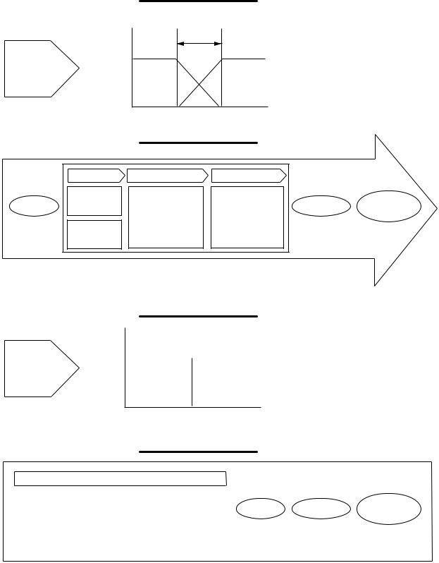
2-2.COMPARISON OF FUZZY WASHER & CONVENTIONAL WASHER
Control Concept
Fuzzy |
1 |
|
Washer |
Low |
High |
|
||
|
0 |
|
|
Washing Process |
|
It senses and controls the categories between yes and no.
|
Sensing |
Fuzzy Control |
Auto Setting |
|
|
|
|
Laundry |
|
#Water Level |
|
Auto |
|
Start |
amount |
|
Washing |
|||
|
|
|||||
sensor |
Fuzzy |
#Wash Time |
power off |
|||
|
|
|||||
|
Water |
Reasoning |
#Wash Action |
|
|
|
|
Level |
|
#Spin Time |
|
|
|
|
sensor |
|
|
|
||
|
|
|
|
|
||
|
|
AUTOMATICALLY |
|
|
||
Control Concept
Conven- |
1 |
|
|
|
|
||
tional |
|
Low |
High |
Washer |
|
0
Washing Process
It works according to the selection of
yes and no.
|
Manual Setting(WF-T902, T851, T802) |
|
|
|
|||||||
|
|
|
|
|
|
|
|
|
|
|
|
|
Water |
|
Wash |
|
Spin |
|
Spin |
|
Start |
Washing |
Manual |
|
Level |
|
Time |
|
Time |
|
Time |
|
|||
|
|
|
|
|
power off |
||||||
|
|
|
|
|
|
|
|
|
|
|
|
|
|
|
|
|
|
|
|
|
|
|
|
|
|
|
|
|
|
|
|
|
|
|
|
5
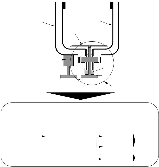
2-3. TURBO DRUM WASH (Except for WF-4020
A) FUNCTIONAL PRINCIPLE
■Pulsator rotates right & left direction by motor driving force and drum rotates in the opposite direction to the pulsator by inertia force & motor driving force, that is achieved by the new clutch and the new drain motor, while only pulsator rotates right & left in a conventional washer.
OUTER TUB |
DRUM |
PULSATOR
|
|
|
MOTOR |
|
|
|
|
|
|
||
|
||
|
|
|
V-BELT |
CLUTCH |
·The drum is possible to rotate by the new clutch removing the counter revolution-protecting device, changing the clutch spring-B to the dual actuating type and releasing the brake band which is activated by the new drain motor operated with two steps.
·Revolution speed step down as follows.
MOTOR |
|
V-belt |
C-PULLEY |
|
|
Planet. gear |
|
PULSATOR |
|
||
|
|
|
|
|
|
(1/5~5.2) |
|
WASH |
|||
|
|
|
|
|
|
|
|
|
|
DRUM |
|
|
|
|
|
|
|
|
|
|
|
|
|
|
|
|
|
|
|
|
|
Directly |
|
|
SPIN |
|
|
|
|
|
|
|
|
|
|
||
|
|
|
|
|
|
|
|
|
DRUM |
||
|
|
|
|
|
|
|
|
|
|
||
|
|
|
|
|
|
|
|
|
|||
|
|
|
|
|
|
|
|
|
|
|
|
6
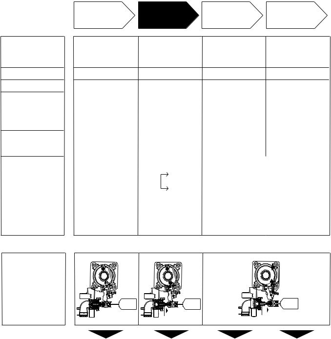
B) WORKING PRINCIPLE BY PROCESS
1. Clutch mechanism
·Clutch Spring-B( )
·Brake Band( )
·Clutch Lever
2. Drain Motor
·SW1
·SW2
3.Wash Motor
4.Power transmitting Sequence
SENSING |
WASH |
|
|
LAUNDRY |
or |
DRAIN |
SPIN |
AMOUNT |
RINSE |
|
|
·Released |
·Released |
·Fastened |
·Fastened |
|
·Fastened |
·Released |
·Released |
·Released |
|
·Do not work |
·1st step moved |
·2nd step moved |
·2nd step moved |
|
|
|
|
|
|
Do not work |
1st step moved |
2nd step moved |
2nd step moved |
|
OFF |
ON |
(Drain Valve open) |
(Drain Valve open) |
|
ON |
ON |
|||
OFF |
OFF |
|||
ON |
ON |
|||
|
|
|||
|
|
|
|
|
Rotates at |
Rotates at |
Doesn’t rotate |
Rotates at |
|
bidirection |
bidirection |
one direction |
||
|
||||
|
|
|||
|
|
|||
|
|
|
|
|
|
Pulsator |
|
|
|
|
& |
|
|
|
|
Drum |
|
|
|
(Drum rotates mainly by reacted force to pulsator action)
5. Working State of
Clutch & Drain
Motor
|
|
|
|
|
|
|
Pulsator rotates at |
Pulsator & Drum |
Pulsator & Drum |
|
Drum rotates |
||
bidirection |
rotates at bidirection |
doesn’t rotates |
|
at one direction |
||
|
each other |
|
|
|
||
7
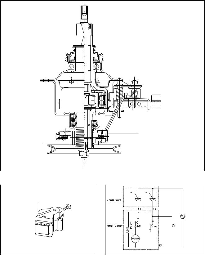
C) STRUCTURE OF THE NEW CLUTCH
Two clutch cams
Two clutch bosses
D) DRAIN MOTOR & CIRCUIT DIAGRAM
3Pin

WASH SPIN
1 PINK |
3 BL / WH |
SW1
4 GY
SW2
2 BL
AC(Rating
Voltage)
8

2-4. REED SWITCH FOR APPLIANCE SAFETY(WF-402, T652A, T452A)
Interrupt system of reed S/W is differed from safety S/W incorporated in the previous models. Reed S/W is located on PWB ASM and operated with a magnetic incorporated inside of Lid-B systemically. If Lid is the closed position, the magnetic operates the contact of Lid S/W. In this case, the machine can do the normal operation because the current pass through the contacts. On the other hand, the contacts is open after Lid is the open position, the machine is stoped because the magnetic is far from the Reed S/W. So do not place any electric appliance with a charging battery, magnetically-driven appliance and magnetic body on the washer. It makes misoperation of washing machine process.
2-5. BALL PRESSURE SENSOR
<Ball Movement> |
|
|
|
<Frequency |
Graph> |
|
|
|
|
|||
[Hz] |
|
|
|
|
|
|
|
|
|
|
|
|
25 |
|
|
|
|
35 |
|
|
|
|
|
|
|
|
|
|
|
|
|
|
|
|
|
|
|
|
20 |
|
|
|
|
30 |
|
|
|
|
|
|
|
15 |
|
|
|
|
25 |
|
|
|
|
|
|
|
|
|
|
|
20 |
|
|
|
|
|
|
|
|
|
|
|
|
|
|
|
|
|
|
|
|
|
10 |
|
|
|
|
15 |
|
|
|
|
|
|
|
5 |
|
|
|
|
10 |
|
|
|
|
|
|
|
|
|
|
|
5 |
|
|
|
|
|
|
|
|
|
|
|
|
|
|
|
|
|
|
|
|
|
0 |
|
|
|
|
0 |
|
|
|
|
|
|
|
|
|
|
|
|
|
|
|
|
|
|
|
|
-5 |
|
|
|
|
[Sec] -5 |
|
|
|
|
|
|
|
0 |
100 |
200 |
300 |
400 |
500 |
0 |
100 |
200 |
300 |
400 |
500 |
600 |
|
|
Normal |
|
|
|
|
Unbalavced |
|
||||
|
|
Condition |
|
|
|
Condition |
|
|
||||
To detect unbalance, the electronic sesing system is used which is differ from safety S/W incoporated in the previous models. In the abnormal operation like unbalance of clothes during spinning, etc, the ball inside of sensor is moved. In this case the inductance of sensor is differ from the initial condition. So micom sense the unbalance condition by ball movement. Ball pressure sensing system is higher safety performance, sesing vertical movements and no deformation and noise by over of safety S/W.
9

2-6.TRIPLE WATER FALL SYSTEM
Water channel
Pulsator
Pulsator |
|
Outer |
vane |
Tub |
Tub |
|
|
Clutch 


 Motor
Motor
<Fig 1> |
<Fig 2> |
■ The washing and rinsing effects have been improved by adopting the water system in
which water in the tub is circulated in a designed pattern. When the pulsator operates during the washing or rinsing process, water below the pulsator is sucked upwards by the rotation of the pulsator vanes, creating a water flow as shown in Fig 1.
The water is then discharged from the upper part of the tub through the water channel provided. circulating water with level and clothes load only and regular water flow as shown in Fig 2.
2-7. AUTOMATIC CORRECTION FOR THE UNBALANCED LAUNDRY DURING SPINNING
When an unbalance of laundry occurs during spinning the unbalance will be automatically corrected
1times but 2nd unbalance will make the machine stop and “UE” is on the DISPLAY. In that case, open the lid, correct the unbalance and press the START/PAUSE button.
2-8. LID SWITCH FOR APPLIANCE SAFETY (WF-T851, T902)
Interrupt system of LID SWITCH is differed from SAFETY SWITCH incorporated in the others models. LID SWITYCH is located on TOP COVER and operated with a magnetic incorporated inside of LID-B systemically. If LID is the closed position, the magnetic operates the contact of LID SWITCH. In this case, the machine can do the normal operation because the current pass through the contacts. On the other hand the contacts is open after LID is the open position, the machine is stopped because the magnetic is far from the LID SWITCH.
Top Cover
Magnet(inside) |
Lid-B |
|
10
2-9. NEW UNBALANCE SENSOR (OPTICAL BALL SENSOR) / WF-T851, T902
To detect unbalance, the optical sensor, BALL SENSOR, is used, which is differed from SAFETY SWITCH incoporated in others models. In normal operation, +5 of voltage is applied between DIODE and TR. In the abnormal operation like unbalance of clothes during spinning, etc, the ball inside of case is moved from the hole. In this case any voltage is not applied between DIODE and TR. That is unbalance detection system of this model.
2-10. AUTO POWER OFF
Power is automatically cut 10 seconds after wash progrom finishes.
11
3.PARTS IDENTIFICATION
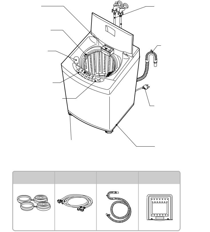
1)WF-T851, T902
START/PAUSE BUTTON
Use to start or stop the washing machine temporarily.
FUNCTION SELECTOR
Powder detergent box for delayed washing/ softener box
INLET HOLE FOR
BLEACH
WASHING WINGS
Vertical movement of washing punch can be operated when a sufficient amount of laundry is deposited.
Set the proper water level, an excessive amount of water may increase entanglement of laundry.
LEVELLING LEGS
Use to level the washing machine for correct balance & spin operation.
HOT WATER SUPPLY
HOSE
COLD WATER SUPPLY HOSE
Make sure the water does not leak.
LINT FILTER
Clean regularly to stop linting on the clothes load.
DRAIN HOSE
Check if the drain hose is located in the laundry tub before operating the washing machine.
POWER PLUG
If the supply cord is damaged, it must be replaced by the manufacture or its service agents or similarly qualified person
in order to avoid a hazard.
BASE
Accessories
Height adjustment |
Inlet hose |
Drain hose |
|
plate |
|||
|
|
2 Pieces |
1 Each for cold and |
hot water |
12
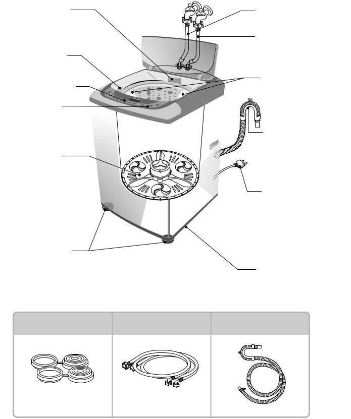
2) WF-T802, T852, T853, T652, T652A
Powder detergent |
|
HOT WATER SUPPLY |
|
box for delayed |
|
HOSE |
|
washing/ softener box |
|
|
|
|
|
COLD WATER SUPPLY |
|
|
|
HOSE |
|
INLET HOLE FOR |
|
Make sure the water |
|
BLEACH |
|
does not leak. |
|
|
|
LINT FILTER |
|
FUNCTION SELECTOR |
|
Clean regularly to stop |
|
|
|
linting on the clothes |
|
START/PAUSE |
|
load. |
|
|
|
||
BUTTON |
|
|
|
Use to start or stop the |
|
|
|
washing machine tem- |
|
DRAIN HOSE |
|
porarily. |
|
Check if the drain hose |
|
WASHING WINGS |
|
is located in the laundry |
|
|
tub before operating the |
||
Vertical movement of |
|
washing machine. |
|
washing punch can be |
|
|
|
operated when a sufficient |
|
|
|
amount of laundry is |
|
POWER PLUG |
|
deposited. |
|
||
|
If the supply cord is |
||
Set the proper water level, |
|
||
|
damaged, it must be |
||
an excessive amount of |
|
||
|
replaced by the manufacture |
||
water may increase |
|
||
|
or its service agents or |
||
entanglement of laundry. |
|
||
|
similarly qualified person |
||
|
|
||
|
|
in order to avoid a hazard. |
|
LEVELLING LEGS |
|
|
|
Use to level the washing |
|
|
|
machine for correct balance |
|
BASE |
|
& spin operation. |
|
|
|
Accessories |
|
|
|
Height adjustment |
Inlet hose |
Drain hose |
|
plate |
|||
|
|
2 Pieces |
1 Each for cold and |
hot water |
13
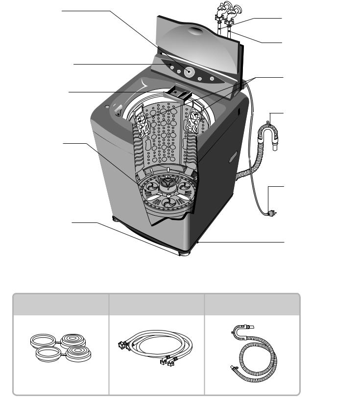
3) WF-T452, T452A, 402
DETERGENT |
HOT WATER SUPPLY |
DISPENSER |
HOSE |
SOFTENER INLET
Softener will automatically flow into the tub.
INLET HOLE FOR
BLEACH
FUNCTION SELECTOR
START/PAUSE BUTTON
Use to start or stop the washing machine temporarily.
LEVELLING LEGS 
Use to level the washing machine for correct balance & spin operation.
 COLD WATER SUPPLY
HOSE
Make sure the water does not leak.
DRAIN HOSE
Check if the drain hose is located in the laundry tub before operating the washing machine.
 LINT FILTER
Clean regularly to stop linting on the clothes load.
POWER PLUG
If the supply cord is damaged, it must be replaced by the manufacture or its service agents or similarly qualified person
in order to avoid a hazard.
BASE
Accessories
Height adjustment |
Inlet hose |
Drain hose |
Silent cover |
|
plate |
||||
|
|
|
 U P
U P 
2 Pieces |
1 Each for cold and |
hot water |
14

4. INSTALLATION INSTRUCTION
A.HOW TO INSTALL THE WASHING MACHINE
■ Selection of the installing place
Install the washer on the horizontal solid floor. If the washer is installed on an unsuitable fioor, it could make considerable noise and vibration.
■ Do not install the washer in the following places
·Where the washer is exposed to direct sunlight. ·Near a heater or heating appliance.
·Where the washer is exposed to freezing temperatures. ·In damp environments such as bathrooms or harmful
environments such as near a coal gas source.
The proper installation of the washing machine can increase the wash effectiveness and the life of it.
If the washer is installed on an inclined floor, it could make considerable noise and vibration and could cause a malfunction.
Use the height adjust rubber to adjust the washing so that it sits properly.
10cm
·Install the washing machine on a level and firm surface.
·Keep the washing machine more than 10cm from the wall to prevent vibration nois during spinning
·The base opening must not be obstructed by carpeting when the washing machine is installed on a carpeted floor.
·Wooden floors may need reinforcing to prevent the normal vibration which occurs with an unbalanced load.
15
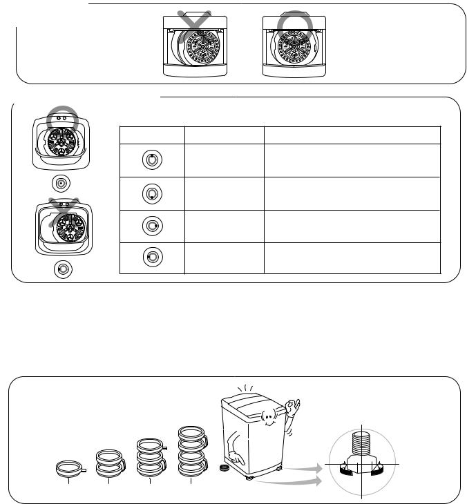
B.HOW TO LEVEL THE WASHING MACHINE
·Check the level of the washing machine using a spirit level on the side of the washer cabinet
· You can check the level also by visually lining up the washer with the fills, adjacent walls or cabinets.
WF-T652(A)
WF-T452(A), 402
WF-T902, T851, T853, T802, T852
■ Horizontal Setting
Location of drop |
Cause |
How to adjust |
When the front is lower.
When the rear is lower.
When the left is lower.
When the right is lower.
•Adjust the front adjusting plate with the adjustable legs(2),or adjust the adjustable legs.
•Adjust the rear adjusting plate with the adjustable legs(2),or adjust the supporting plate.
•Adjust the left part of the front and rear adjusting plates or the supporting plate.
•Adjust the right part of the front and rear adjusting plates or the supporting plate.
·You can level the washer using the A.L spindle fitted to the cabinet.
·Screw the A.L SPINDLE legs up or down as required.
·Additional height adjustment plates are provided in the accessory bag. These fit under A.L SPINDLE if required to allow for greater adjustment of the legs.
·When washing machine does not even out, turn A.L SPINDLE right or left to be level.
·Should the height adjustment exceed the maximum allowed by the A.L SPINDLE,please height adjustment plates provided under the legs as shown in the diagram.
UP  DOWN
DOWN
1 plate used |
2 plate used |
3 plate used |
4 plate used |
A.L SPINDLE |
|
16
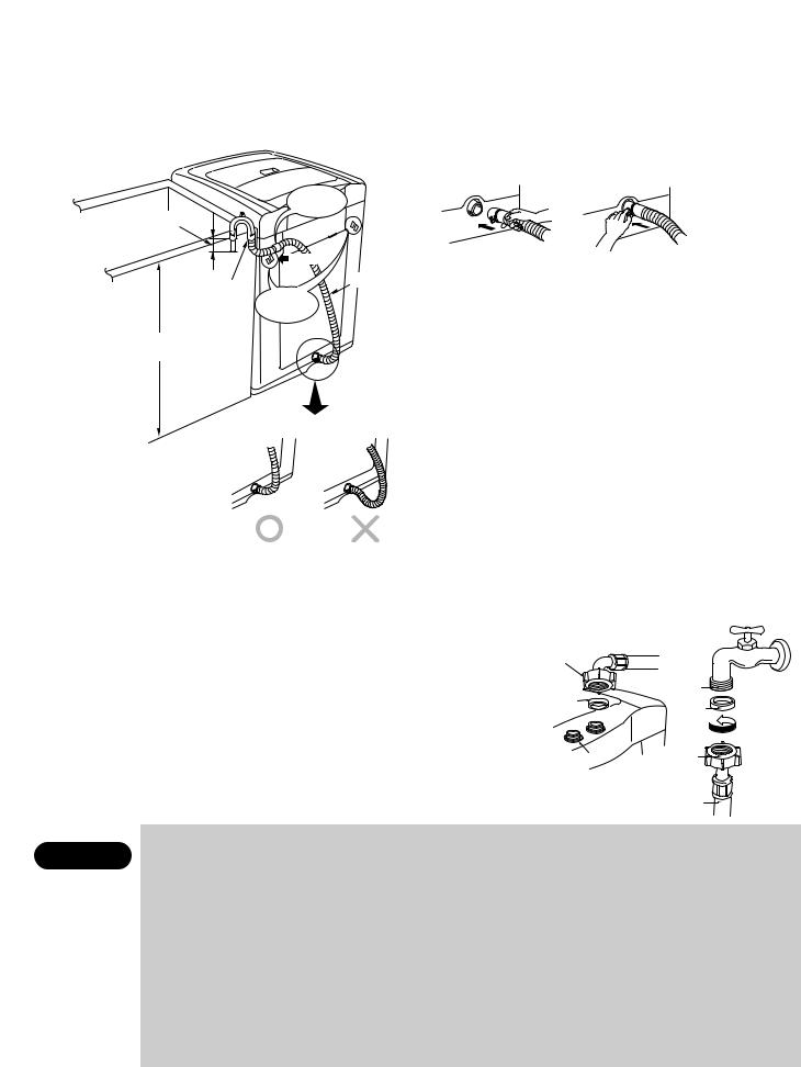
C. How to install the drain hose
Holder
Within 50mm
Hose |
Drain Hose |
|
Holes |
||
Guide |
||
|
For Holder |
0.9~
1.2m
Holes for the Holder
1.Fit the machine end of the drain hose to the outlet of the drain pump and tighten the clamp.
2.Put the other end of the drain hose over the standpipe or wash tub.
3.Fit the plastic holder into either holes for the holder at the rear of the machine. The holder is possible to fit at either direction according to location of the standpipe. Make sure that the holder keeps firmly the drain hose so that the drain hose should not fall down as shown in the fig.
(WF-T851, T853, T802, T852)
NOTE :
●To prevent syphoning, the drain hose should not extend more than 50 mm from the end of the hose guide.
●The discharge height should be approximately 0.9~1.2m from the floor.
D. Flooding drainage
● You machine requires a floor drainage slope (or hole) that will SAFELY DISPOSE of the FULL FLOW of any water that may leak out should the machine malfunction.
It is therefore the OWNER'S RESPONSIBILITY to make sure this machine is installed in an area with a drain hole (or slope) that will prevent any possibility of water damage to floor coverings or property. 
E. Connect inlet hose |
MACHINE |
|
|
END |
|
||
|
|
||
● Check that sealing washers are firmly seated. |
SEALING |
|
|
● Attach the curved end of the hose to the inlet valve of the washing machine; Tighten the |
|
||
WASHER |
SEALING |
||
|
WASHER |
||
coupling nuts securely by hand. (Fig. 1) |
|
|
|
● Attach the stsraight end of the hose to the tap. |
|
|
|
Tighten the coupling nuts securely by hand. (Fig. 2) |
INLET |
|
|
VALVE |
|
||
● Either hose can be attached to hot inlet valve and tap. |
<Fig.1> |
|
|
● Turn on the taps and check for leaks. Tighten the coupling nuts firmly if there is any |
|
||
leakage. If water pressure is strong, close the water tap completely then open it slightly. |
|
|
|
|
● Do not install the washer where it is directly exposed to sunlight, wind, rain etc. |
|
|
CAUTION |
● Plug the power cord of this washer into a properly installed standard power point that is switched & earthed. |
||
TWIST
<Fig.2>
●Your machine requires a floor drainage slope(or hole) that will SAFELY DISPOSE of the FULL FLOW of any water that may leak out should the machine malfunction. It is therefore the OWER’S RESPONSIBILITY to make sure this machine is installed in an area with a drain hole (or slope) that will prevent any possibility of water damage to floor coverings or property.
●Permissible water temperature : Max 70ºC (160ºF)
●Permissible water pressure : Max 116psi (800kpa, 8kg/cm2), Min 4psi (30kpa, 0.3kg/cm2)
●If water temperature & pressure is greater than above, it may cause damage to the machine. If you have uncontrolled water temperature & pressure you should fit a temperature &pressure relief valve to ensure that water temperature & pressure relief valve to ensure that water temperature & water pressure remains within the safe limits. Consult a plumber or electrician if you are unable to adjust water temperature and pressure.
●Do not over tighten the coupling nuts with a tobl. Inlets are plastic : Do not strip or corssthread.
17
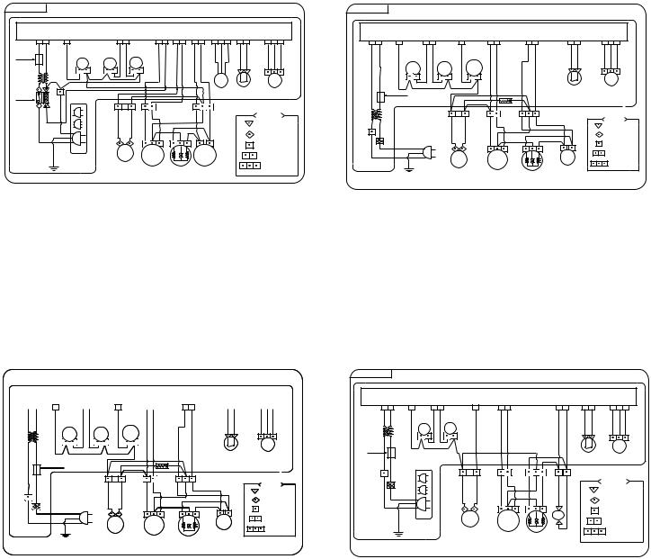
6. SCHEMATIC DIAGRAM
WF-T851 |
WF-T853 |
BASE / LINE
WIRING DIAGRAM
BASE / LINE
WIRING DIAGRAM
|
|
|
|
|
CONTROLLER ASM |
|
|
|
|
|
|
|
|
|
|
|
|
|
|
|
CONTROLLER ASM |
|
|
|
|
|
|
||||||||
RD (PK) |
WH |
YL(LGN) |
GY(OR) |
WH |
BL (BN) |
|
WH |
|
VL(SBL) |
BL(OR) |
RD(PK) |
BL(WH) |
YL(LGN) |
|
WH(OR) |
GY(OR) |
BL(WH) |
VL(BN) |
BL(WH) |
||||||||||||||||
|
2 |
1 |
1 |
1 |
2 |
1 |
2 |
2 |
1 |
1 |
2 |
1 |
2 |
3 |
1 |
2 |
1 |
2 |
3 |
1 |
2 |
1 |
2 |
1 |
|
1 |
2 |
1 |
1 |
2 |
1 |
2 |
1 |
2 |
3 |
BN |
BL |
BN |
GY OR |
BL WH GY PK |
|
YL RD |
YL RD BL |
|
WH WH |
OR WH VL |
WH BK |
BL |
OR GY |
|
BN |
BL PK |
RD YL |
WH WH |
OR WH VL |
||||||||||||||||
|
|
|
/ |
|
|
/ |
|
|
|
|
|
|
|
|
|
|
|
|
|
|
|
|
|
|
|
/ |
/ |
|
|
|
|
|
|
|
|
FUSE |
|
|
WH |
|
|
WH |
|
|
|
|
|
|
|
|
|
|
|
|
|
|
|
|
|
|
|
WH |
WH |
|
|
|
|
|
|
|
|
|
|
|
RINSE |
C.V |
H.V |
RD |
|
|
|
|
|
|
|
|
|
|
|
|
|
|
|
|
H.V |
|
C.V |
|
|
|
|
|
|
|
|
|
|
|
|
|
WH BL |
|
|
|
|
|
|
|
|
|
|
|
|
|
|
|
|
|
|
|
SHOWER |
|
|
|
|
|
|
|
|
|
|||
|
|
BL |
BL |
BL |
BL |
|
|
|
|
|
|
|
|
|
|
|
|
|
|
|
|
|
RD |
|
|
WH |
BL |
|
|
|
|
|
|
|
|
|
|
|
|
|
|
|
|
|
|
|
|
|
|
|
|
|
|
|
|
|
|
|
|
|
|
|
|
|
|
|
|
|
|
||
|
|
|
|
|
|
BL |
|
|
|
|
|
|
|
|
|
|
|
|
|
|
|
|
BL |
|
|
BL |
|
|
|
|
SAFETY |
PRESSURE |
|||
AUTO OFF |
|
WH |
|
|
|
|
|
|
|
|
|
BALL |
|
LID |
PRESSURE |
|
|
FUSE |
|
|
|
BL |
|
|
BL |
|
SWITCH |
SWITCH |
|||||||
SWITCH |
|
|
|
|
|
|
|
|
|
|
|
SENSOR |
SWITCH |
SWITCH |
|
|
|
|
|
|
GY |
|
|
GY |
|
|
|
|
|
|
|||||
|
|
|
|
|
|
|
|
GY |
1uF |
|
|
|
|
GY |
BL |
BL PK |
YL BL RD |
NOTES |
|
|
|
|
|
|
|
|
|
|
/ |
|
|
BL |
GY |
BL |
PK |
RD BL YL |
|
NOTES |
BN |
|
|
WH |
RD |
#180 RECEP |
|
|
/ |
|
|
|
#187 |
(BK) |
BL ( WH) |
|
BL |
|
|
|
WH |
|
|
|
Receptacle |
|
|
YL |
|
WH |
|
|
|
|
|||||
|
|
#250 RECEP |
|
|
|
|
RD |
#250 |
||||
|
|
|
|
|
|
BK |
|
|
|
BL |
YL |
Receptacle |
|
|
|
|
|
1 PIN HOUS'G |
(BN) |
|
|
|
1 Pin |
||
|
|
|
|
|
|
|
|
|
|
|||
|
|
|
|
|
|
BK |
|
|
|
|
|
Housing |
|
|
PUMP |
DRAIN |
|
2 PIN HOUS'G |
GR/YL |
|
|
|
|
|
2 Pin |
|
GN/YL |
|
WH |
|
|
DRAIN |
|
|
Housing |
|||
|
(GN) |
|
MOTOR |
|
|
|
PUMP |
|
|
|
|
|
|
|
|
|
|
|
|
MOTOR |
|
|
3 Pin |
||
|
|
|
|
|
3 PIN HOUS'G |
|
|
|
|
|
||
|
|
|
|
MOTOR CAPACITOR |
|
|
|
|
|
|
Housing |
|
|
|
|
|
|
|
|
|
|
MOTOR |
|
CAPACITOR |
WF-T802/T852 |
WF-T452 |
BASE / LINE |
|
|
|
|
|
WIRING |
|
|
DIAGRAM |
|
|
|
|
|
|
|
|
|
|||||||
|
|
|
|
|
|
|
|
|
|
|
|
|
|
|
|
|
|
|
|
|
|||||
|
|
|
|
|
|
|
|
|
|
|
|
|
|
|
|
|
|
|
|
|
|||||
|
|
|
|
|
|
|
|
|
|
CONTROLLER ASM |
|
|
|
|
|
|
|
|
|
|
|||||
|
RD(PK) |
BL(WH) |
YL(LGN) |
WH(OR) |
GY(OR) |
BL(WH) |
VL(BN) |
|
BL(WH) |
|
|||||||||||||||
|
|
1 |
2 |
|
1 |
|
2 |
1 |
|
1 |
|
1 |
2 |
|
1 |
2 |
|
1 |
2 |
|
|
1 |
2 |
3 |
|
|
WH BK |
BL |
OR GY |
BN |
BL PK |
RD YL |
WH WH |
OR WH VL |
|
||||||||||||||||
//
WH WH
H.V |
C.V |
SHOWER |
|
|
RD |
WH |
BL |
|
|
BL |
BL |
|
SAFETY |
PRESSURE |
|
BL |
|
||
|
BL |
SWITCH |
SWITCH |
GY |
GY |
FUSE |
|
GY |
1uF |
BK |
|
|
|
|
BL GY |
BL PK |
RD BL YL |
|
NOTES |
|
/ |
|
|
#187 |
WH |
WH |
|
|
Receptacle |
|
|
RD |
#250 |
|
BK |
|
BL |
YL |
Receptacle |
(BN) |
|
1 Pin |
||
|
|
|
||
BK |
|
|
|
Housing |
GR/YL |
|
|
|
2 Pin |
WH |
DRAIN |
|
|
Housing |
PUMP |
|
|
|
|
MOTOR |
|
|
3 Pin |
|
|
|
|
||
|
|
|
|
Housing |
MOTOR CAPACITOR
BASE / LINE |
|
|
|
|
|
WIRING |
DIAGRAM |
|
|
|
|
|
|
|||
|
|
|
|
|
|
|
|
|
|
|
|
|||||
|
|
|
|
|
|
CONTROLLER ASM |
|
|
|
|
|
|
|
|||
RD (PK) |
BL(WH) |
YL(LGN) |
|
WH(OR) |
GY(OR) |
BL(WH) |
VL(BN) |
BL(WH) |
||||||||
1 |
2 |
1 |
2 |
1 |
|
1 |
|
2 |
1 |
2 |
1 |
1 |
2 |
1 |
2 |
3 |
WH BK |
BL |
OR GY |
|
GY |
BL PK |
|
YL RD |
WH WH |
OR WH VL |
|||||||
|
|
|
|
|
|
|
/ |
|
|
|
|
|
|
|
|
|
|
|
|
|
|
|
|
WH |
|
|
|
|
|
|
|
|
|
|
|
H.V |
C.V |
|
|
|
|
|
|
|
|
|
|
|
|
|
|
|
RD |
|
|
BL |
|
|
|
|
|
|
|
|
|
|
|
FUSE |
|
|
BL |
|
|
|
|
|
|
|
|
|
|
|
|
|
|
|
|
|
|
BL |
|
|
|
RD |
|
|
|
|
|
|
|
|
|
|
|
BL |
|
|
|
|
|
|
SAFETY |
PRESSURE |
||||
|
|
|
|
|
|
|
|
|
YL |
|
||||||
|
|
|
|
|
|
|
|
|
|
|
SWITCH |
SWITCH |
||||
WH |
|
|
|
|
|
|
|
|
|
|
|
|
|
|
|
|
|
|
|
|
BL |
GY |
BL PK |
RD BL YL |
YL RD |
|
|
NOTES |
|
||||
|
BK(BN) |
|
|
|
|
/ |
|
|
|
|
|
|
#180 RECEP |
|||
BL |
|
|
|
|
|
|
WH |
|
|
|
|
|
|
|||
(WH) |
BN ( BK) |
|
|
|
|
|
|
BL |
|
|
|
|
|
|
|
|
|
|
|
|
|
|
|
|
|
|
|
#250 RECEP |
|||||
|
|
|
|
|
|
|
|
|
|
|
|
|||||
|
|
|
|
|
|
|
|
|
|
|
|
|
|
|||
|
|
|
|
|
|
|
|
|
|
|
|
|
|
1 PIN HOUS'G |
||
|
|
GN/YL |
|
|
|
PUMP |
|
DRAIN |
|
|
|
|
2 PIN HOUS'G |
|||
|
|
(GN) |
|
|
|
|
|
MOTOR |
|
|
|
|
|
|
|
|
|
|
|
|
|
|
|
|
|
MOTOR |
CAPACITOR |
|
|
3 PIN HOUS'G |
|||
|
|
|
|
|
|
|
|
|
|
|
|
|
|
|||
18

WF-T652 |
|
|
|
|
|
|
|
|
|
|
|
WF-T902 |
||
BASE / LINE |
|
|
|
|
WIRING |
DIAGRAM |
|
|
|
|
|
|||
|
|
|
|
|
|
|
|
|
|
|||||
|
|
|
|
|
CONTROLLER ASM |
|
|
|
|
|
|
|||
RD(PK) |
BL(WH) |
YL(LGN) |
WH(OR) |
GY(OR) |
BL(WH) |
VL(BN) |
BL(WH) |
|||||||
1 |
2 |
1 |
2 |
1 |
1 |
2 |
1 |
1 |
2 |
1 |
2 |
1 |
2 |
3 |
WH BK |
BL |
OR |
GY |
GY |
BL |
PK |
RD |
YL |
WH |
WH |
OR WH VL |
|||
|
|
|
|
|
|
/ |
|
|
|
|
|
|
|
|
|
|
|
|
|
|
WH |
|
|
|
|
|
|
|
|
|
|
H.V |
C.V |
|
|
|
|
|
|
|
|
|
|
|
|
|
RD |
|
|
BL |
|
|
|
|
|
|
|
|
|
|
|
|
BL |
|
|
|
|
|
|
|
|
|
|
|
FUSE |
|
|
|
|
|
BL |
|
|
|
SAFETY |
PRESSURE |
|||
|
|
|
|
|
|
|
|
|
||||||
|
|
|
|
|
BL |
|
|
|
|
SWITCH |
SWITCH |
|||
|
|
|
|
|
|
|
|
|
|
|
|
|
|
|
WH |
|
|
|
|
|
|
|
|
|
|
|
|
|
|
|
|
|
|
|
BL GY |
BL PK |
RD BL YL |
|
|
|
NOTES |
|||
|
|
BK(BN) |
|
|
|
|
|
#187 |
||||||
BL |
|
|
|
|
/ |
|
|
|
|
|
|
|||
|
|
|
|
|
WH |
|
|
|
YL |
|
|
Receptacle |
||
(WH) |
BN ( BK) |
|
|
|
|
|
|
|
|
|
|
#250 |
||
|
|
|
|
|
|
BL |
|
RD |
|
|
Receptacle |
|||
|
|
|
|
|
|
|
|
|
|
|
1 Pin |
|||
|
|
|
|
|
|
|
|
|
|
|
|
|
||
|
|
|
|
|
|
|
|
|
|
|
|
|
Housing |
|
|
|
|
|
|
|
|
|
|
|
|
|
|
2 Pin |
|
|
|
GN/YL |
|
|
|
|
|
|
|
|
|
|
Housing |
|
|
|
|
|
|
|
|
|
|
|
|
|
3 Pin |
||
|
|
(GN) |
|
|
|
|
|
|
|
|
|
|
||
|
|
|
|
|
|
|
|
|
|
|
|
Housing |
||
|
|
|
|
|
|
|
|
|
|
|
|
|
||
|
|
|
|
|
PUMP |
DRAIN |
MOTOR |
CAPACITOR |
|
|
|
|||
|
|
|
|
|
|
MOTOR |
|
|
|
|
|
|
|
|
WF-402
19

6. OPERRATING INSTRUCTION
1) WF-T851
Fully automatic control
●The Normal program is used for average day to day washing.
●Press POWER ON button.
●Load clothes.
Preparation before wash
●Add detergent, bleach and conditioner as desired.
●Close the lid and press START/PAUSE button.
●The water level lights will scroll up and down while the washer is working out the optimum water level for your clothes load.
Sort your washing into separate wash loads
●Each load of washing should contain clothing which needs the same washing conditions. For example, you should not wash delicate clothes with very dirty work clothes.
●Some fabrics are lint collectors and can pick up lint,dirt and colour
from other fabrics, which are lint producers. Some examples are listed below.
LINT COLLECTORS |
LINT PRODUCERS |
Corduroy |
Towels |
Synthetics |
Nappies |
Permanent press fabrics |
Chenille / Candlewick |
Make sure that you wash lint collectors separately from lint producers.
¥Upon loading laundry, it displays the correct amount of detergent to be added according to the amount of laundry(based on concentrated detergent).
●Check if laundry is washable in water.
●Wash oily or dyed laundry separately.
●Wash fluffy laundry by turning it inside out
●Be sure to remove things such as keys, pins and coins from the laundry.
●Wash fluffy lanundry by turning it inside out.
●Wash delicate clothes, wrapping them in a nylon net.
¥Used to select proper water temperature of washing wa-
ter,
[ WARM(HOT+COLD) → HOT →COLD] mode repeats.
¥Use it to select hot or cold water. (When hot water only is selected, hot water is suppled for washing and cold water are supplied for rinsing)
Manual control
●Other programmes are selected as follows.
●Press POWER ON button.
●Load clothes.
●Add detergent, bleach and conditioner as desired.
●Select temperature, level, process, program and options as described below.
●Close the lid and press START/PAUSE button.
|
|
|
|
|
|
|
|
|
|
¥ Indicates the current |
|
¥ Use it to select washing pro- |
|
¥ Used to indicate the time left of all processes or reservation. |
|
¥ Use it turn on and turn off. |
|||
washing status. |
|
grams. |
|
¥ In case of abnormal operation, the following indications are |
|
By pressing the button [turn |
|||
¥ Next step is lit, current |
|
¥ By pressing the button, it cycles |
|
displayed. |
|
|
|
|
on turn off] are repeated. |
step blinks and finished |
|
[NORMAL → HEAVY → SPEEDY |
|
Abnormal water supply : |
lamp blinks. |
|
¥ Electric power automatically |
||
step is turned off. |
|
→ WOOL]. |
|
Abnormal drainage : |
|
lamp blinks. |
|
turns off 10 seconds after the |
|
|
|
|
|
Abnormal spin : |
lamp blinks. |
|
|
washing cycle finishes with |
|
|
|
|
|
Abnormal water level sensing : |
lamp blinks. |
|
"boo-" sound. |
||
|
|
|
|
Abnormal lid open : |
|
lamp blinks. |
|
|
|
|
|
|
|
Abnormal over flooding sensing : |
lamp blinks. |
|
|
||
|
|
|
|
|
|
|
|
|
|
|
|
DETERGENT |
|
|
|
|
|
|
|
|
|
EX |
|
|
|
|
HOUR |
|
MINUTE |
||
|
|
|
|
|
||||||
WARM |
¥ |
|
|
|
|
|
||||
|
|
|
|
DELAY / TIME LEFT |
||||||
L |
|
|
|
|
||||||
|
|
|
|
|
|
|
|
|
|
|
HOT COLD |
¥ |
|
|
GENTLE |
|
SOAK |
|
|
|
|
|
|
|
|
|
|
|
||||
|
M |
|
|
1 |
|
60 |
|
AUTO OFF |
|
|
|
¥ |
|
|
3 |
START |
21 |
|
|
|
|
|
S |
|
|
|
|
|
|
|||
|
|
|
PAUSE |
|
|
|
|
|||
WATER |
|
|
|
5 |
15 |
|
|
|
|
|
|
|
|
|
|
|
|
|
|||
TEMP. |
WATER |
|
10 |
DELAY |
||||||
7 |
|
|||||||||
|
LEVEL |
|
5 |
START |
||||||
|
(MIN) |
|
||||||||
|
|
|
|
|
|
(MIN) |
|
|
|
|
|
|
|
|
1 2 |
3 4 5 (TIMES) |
|
|
|
|
|
|
|
|
|
|
|
|
|
|
|
|
|
|
|
|
|
|
|
|
|
|
|
|
|
|
¥ Used to lock or unlock the |
|
¥ By pressing the button, it cycles |
control buttons to prevent |
|
[LARGE → LARGE ¥ EX-LARGE |
all the setting from being |
|
→ EX-LARGE → SMALL → |
changed by a child. |
|
SMALL ¥ MEDIUM → MEDIUM → |
¥ For locking, push both |
|
MEDIUM ¥ LARGE → LARGE]. |
buttons simultaneously |
|
¥ At NORMAL, HEAVY or SOAK |
and for unlocking, push |
|
program, water level is automati- |
them one more in wash- |
|
cally based on the amount of |
ing process. |
|
laundry. |
|
|
¥ Water level can be adjusted ever |
|
|
when the washer is in operation. |
|
|
|
¥Use this function for delayed washing.
¥Use it to set the delay time.
¥By pressing the button, it cycles [3 → 4 → 5 →
... → 11 → 12 → 14 → 16 → ... → 46 → 48 → 3] hours. (up to 48 hours can be delayed)
¥To cancel delay time, turn the power switch off.
¥Use it to start or pause temporarily.
¥Pressing the button repeats start and temporary pause.
¥After 10 minutes in a temporary pause state, the power will automatically turn off.
¥ Wash :
Use it to change washing time.
By pressing the button[21min → SOAK 5min → SOAK 10min → SOAK 15min → SOAK 21min → OFF → 5min → 10min → 15min]
SOAK is used to remove old or hardened dirt more effectively.
Soak time is about 60 minutes. (You cannot change in WOOL program.)
¥ Rinse :
Use it to change the frequency of rinse. By pressing the button.
[rinse 1 → rinse 2 → rinse 3 → rinse 4 → rinse 5 → OFF → rinse 1] are repeated. When you select rinse only, the operation starts with water supply.
¥ Spin :
Use it to change the spinning time.
By pressing the button [5 min → 7 min → OFF → 1 min → 3 min → 5 min].
20 |
21 |
 Loading...