


 Loading...
OWNER'S MANUAL
LAUNDRY CENTER
Before beginning installation, read these instructions carefully. This will simplify installation and ensure that the product is installed correctly and safely. Leave these instructions near the product after installation for future reference.
ENGLISH
WK22**S6
www.lg.com
MFL71728958 |
Copyright © 2020-2021 LG Electronics Inc. All Rights Reserved. |
Rev.05_041421 |
TABLE OF CONTENTS
This manual may contain images or content that may be different from the model you purchased.
This manual is subject to revision by the manufacturer.
SAFETY INSTRUCTIONS |
|
READ ALL INSTRUCTIONS BEFORE USE |
...........................................................4 |
WARNING............................................................................................................ |
6 |
INSTALLATION |
|
Parts and Specifications .................................................................................. |
12 |
Installation Place Requirements .................................................................... |
15 |
Unpacking the Appliance ................................................................................ |
17 |
Connecting Electric Dryer ............................................................................... |
18 |
Installing the Vent Kit of Dryer....................................................................... |
22 |
Venting the Dryer............................................................................................. |
23 |
Connecting Gas Dryer ..................................................................................... |
24 |
Connecting the Water Supply Hose............................................................... |
26 |
Installing the Drain Hose ................................................................................ |
28 |
Levelling the Appliance ................................................................................... |
29 |
Disassembly...................................................................................................... |
32 |
OPERATION-WASHER |
|
Operation Overview......................................................................................... |
34 |
Preparing the Wash Load ............................................................................... |
35 |
Adding Detergents and Softeners ................................................................. |
36 |
Control Panel and Programme Table............................................................ |
38 |
Extra Options and Functions .......................................................................... |
44 |
OPERATION-DRYER |
|
Operation Overview......................................................................................... |
46 |
Preparing the Laundry .................................................................................... |
46 |
Control Panel and Programme Table............................................................ |
48 |
Extra Options and Functions .......................................................................... |
53 |
SMART FUNCTIONS |
|
Using LG ThinQ Application............................................................................ |
56 |
Smart Diagnosis ............................................................................................... |
58 |
MAINTENANCE |
|
Washer .............................................................................................................. |
60 |
Dryer.................................................................................................................. |
63 |
TROUBLESHOOTING |
|
Washer .............................................................................................................. |
65 |
Dryer.................................................................................................................. |
72 |
Common............................................................................................................ |
78 |
4 SAFETY INSTRUCTIONS
SAFETY INSTRUCTIONS
READ ALL INSTRUCTIONS BEFORE USE
The following safety guidelines are intended to prevent unforeseen risks or damage from unsafe or incorrect operation of the appliance.
The guidelines are separated into ‘WARNING’ and ‘CAUTION’ as described below.
Safety Messages
This symbol is displayed to indicate matters and operations that can cause risk. Read the part with this symbol carefully and follow the instructions in order to avoid risk.
WARNING
This indicates that the failure to follow the instructions can cause serious injury or death.
CAUTION
This indicates that the failure to follow the instructions can cause the minor injury or damage to the product.
Safety for a Dryer
 WARNING
Fire Hazard
Failure to follow safety warnings exactly could result in serious injury, death or property damage.
Do not install a booster fan in the exhaust duct.
Install all clothes dryer in accordance with the installation instructions of the manufacturer of dryer.
SAFETY INSTRUCTIONS 5
 WARNING:
FIRE OR EXPLOSION HAZARD
Failure to follow safety warnings exactly could result in serious injury, death or property damage.
•Do not store or use gasoline or other flammable vapors and liquids in the vicinity of this or any other appliance.
•WHAT TO DO IF YOU SMELL GAS
-Do not try to light any appliance.
-Do not touch any electrical switch; do not use any phone in your building.
-Clear the room, building or area of all occupants.
-Immediately call your gas supplier from a neighbor’s phone. Follow the gas supplier’s instructions.
-If you cannot reach your gas supplier, call the fire department.
•Installation and service must be performed by a qualified installer, service agency or your gas supplier.
<![endif]>ENGLISH
6 SAFETY INSTRUCTIONS
 WARNING - Risk of Fire
Install the clothes dryer according to the manufacturer’s instructions and local codes.
•Clothes dryer installation must be performed by a qualified installer.
•Do not install a clothes dryer with flexible plastic venting materials. If flexible metal (foil type) duct is installed, it must be of a specific type identified by the appliance manufacturer as suitable for use with clothes dryers. Flexible venting materials are known to collapse, be easily crushed, and trap lint. These conditions will obstruct clothes dryer airflow and increase the risk of fire.
•To reduce the risk of severe injury or death, follow all installation instructions.
WARNING
 WARNING
•To reduce the risk of explosion, fire, death, electric shock, injury or scalding to persons when using this product, follow basic precautions, including the following:
Technical Safety
•This appliance is not intended for use by persons (including children) with reduced physical, sensory or mental capabilities, or lack of experience and knowledge, unless they have been given supervision or instruction concerning use of the appliance by a person responsible for their safety.
•Children should be supervised to ensure that they do not play with the appliance.
•The inlet water pressure must be between 50 kPa and 800 kPa.

SAFETY INSTRUCTIONS 7
•Use a new hose or hose-set supplied with the appliance. Reusing old hoses can cause a water leak and subsequent property damage.
• Ventilation openings must not be obstructed by a carpet.
• Do not dry unwashed items in the appliance. |
<![if ! IE]> <![endif]>ENGLISH |
|
|
• Fabric softeners, or similar products, should be used as specified by |
|
the fabric softener instructions. |
|
• Remove all objects from pockets such as lighters and matches. |
|
• Never stop the appliance before the end of the drying cycle unless all |
|
items are quickly removed and spread out so that the heat is |
|
dissipated. |
|
• The appliance is not to be used if industrial chemicals have been used |
|
for cleaning. |
|
• Items that have been soiled with substances such as cooking oil, |
|
vegetable oil, acetone, alcohol, petroleum, kerosene, spot removers, |
|
turpentine, waxes and wax removers should be washed in hot water |
|
with an extra amount of detergent before being dried in the |
|
appliance. |
|
• Do not drink the condensed water. Failure to do so may result in food- |
|
borne illnesses. |
|
• If the supply cord is damaged, it must be replaced by the |
|
manufacturer or its service agents or similarly qualified person in |
|
order to avoid a hazard. |
|
• The lint filter must be cleaned frequently. |
|
• Lint must not to be allowed to accumulate around the appliance. |
|
• Do not spray dry cleaning detergent directly onto the appliance or |
|
use the appliance to dry clothes left with dry cleaning detergent. |
|
• Do not dry clothes stained with oil substances. Oil substances |
|
(including edible oils) stained on clothes cannot be completely |
|
removed even after washing with water. |
|
• The appliance must not be supplied through an external switching |
|
device, such as a timer, or connected to a circuit that is regularly |
|
switched on and off by a utility. |
|
• Remove clothes from the product immediately when drying is |
|
complete or the power is turned off during the drying process. |
|

8 SAFETY INSTRUCTIONS
Leaving clothes that has been dried in the appliance unattended could result in fire. Clothes not removed from the appliance after drying could result in fire. Remove clothes immediately after drying, and then hang or lay the clothes flat to cool.
• This appliance is intended to be used in household only.
Maximum Capacity
The maximum capacity in some cycles for dry clothes to be used is
Wash : 22 kg, Dry : 11 kg (Dry Clothes) / 22 kg (Wet Clothes).
Installation
•Never attempt to operate the appliance if it is damaged, malfunctioning, partially disassembled, or has missing or broken parts, including a damaged cord or plug.
•This appliance should only be transported by two or more people holding the appliance securely.
•Do not install the appliance in a damp and dusty place. Do not install or store the appliance in any outdoor area, or any area that is subject to weathering conditions such as direct sunlight, wind, rain, or temperatures below freezing.
•Make sure the power plug is completely pushed into the power outlet.
•Do not plug the appliance into multiple outlet sockets, power boards, or an extension power cable.
•Do not modify the power plug provided with the appliance. If it does not fit the power outlet, have a proper outlet installed by a qualified electrician.
•This appliance is equipped with a power cord having an equipmentearthing / grounding conductor (earthing pin) and a grounding power plug. The power plug must be plugged into an appropriate outlet socket that is installed and earthed / grounded in accordance with all local codes and ordinances.
•Improper connection of the equipment-grounding conductor can result in risk of electric shock. Check with a qualified electrician or

SAFETY INSTRUCTIONS 9
service personnel if you are in doubt as to whether the appliance is properly grounded.
•This appliance must not be installed behind a lockable door, a sliding 
door or a door with a hinge on the opposite side to that of the appliance, in such a way that a full opening of the appliance door is ENGLISH restricted.
•Tighten the drain hose to avoid separation.
•If the power cord is damaged or the hole of the socket outlet is loose, do not use the power cord and contact an authorized service centre.
Operation
•To avoid breaking the door glass, do not push too hard on the door when closing.
•Do not apply any sharp objects to the control panel in order to operate the appliance.
•Do not attempt to separate any panels or disassemble the appliance.
•Do not repair or replace any part of the appliance. All repairs and servicing must be performed by qualified service personnel unless specifically recommended in this Owner's Manual. Use only authorized factory parts.
•Do not push down the door excessively, when the appliance door is open.
•Do not put animals, such as pets into the appliance.
•Do not wash rugs, mats, shoes or pet blankets, stuffed toys, or any other items other than clothes or sheets, in this machine.
•Keep the area underneath and around the appliance free of combustible materials such as lint, paper, rags, chemicals, etc.
•Do not leave the appliance door open. Children may hang on the door or crawl inside the appliance, causing damage or injury.
•Do not put in, wash or dry articles that have been cleaned in, washed in, soaked in, or spotted with combustible or explosive substances (such as waxes, wax removers, oil, paint, gasoline, degreasers, drycleaning solvents, kerosene, petrol, spot removers, turpentine,

10 SAFETY INSTRUCTIONS
vegetable oil, cooking oil, acetone, alcohol, etc.). Improper use can cause fire or explosion.
•Do not use or store flammable or combustible substances (ether, benzene, alcohol, chemical, LPG, combustible spray, gasoline, thinner, petroleum, insecticide, air freshener, cosmetics, etc.) near the appliance.
•Never reach into the appliance while it is operating. Wait until the drum has completely stopped.
•Do not touch the door during a high temperature programme.
•In case of a water leak from the appliance or flood, disconnect the power plug and contact the LG Electronics customer information centre.
•Turn off water taps to relieve pressure on hoses and valves and to minimize leakage if a break or rupture should occur. Check the condition of the fill hoses; they should be replaced after 5 years.
•If there is a gas leakage (isobutane, propane, natural gas, etc.) within the home, do not touch the appliance or power plug and ventilate the area immediately.
•If the drain hose or inlet hose is frozen during winter, use it only after thawing.
•Keep all washing detergents, softener and bleach away from children.
•Do not touch the power plug or the appliance controls with wet hands.
•Do not bend the power cable excessively or place a heavy object on it.
•Avoid touching any water that is drained from the appliance during the wash.
•Make sure that drainage is working properly. If water is not drained properly, your floor may get flooded.
•When the air temperature is high and the water temperature is low, condensation may occur and thus wet the floor.
•Wipe off dirt or dust on the contacts of the power plug.
SAFETY INSTRUCTIONS 11
Maintenance
• Disconnect the appliance from the power supply before cleaning the appliance. Setting the controls to the OFF or stand by position does not disconnect this appliance from the power supply.
•Securely plug the power plug in the outlet socket after completely removing any moisture and dust.
•Do not spray water inside or outside the appliance to clean it.
•Never unplug the appliance by pulling on the power cable. Always grip the power plug firmly and pull straight out from the outlet socket.
•Only qualified service personnel from LG Electronics service centre should disassemble, repair, or modify the appliance. Contact an LG Electronics customer information centre if you move and install the appliance in a different location.
<![endif]>ENGLISH
Disposal
•Before discarding an old appliance, unplug it. Cut off the cable directly behind the appliance to prevent misuse.
•Dispose of all packaging materials (such as plastic bags and styrofoam) away from children. The packaging materials can cause suffocation.
•Remove the door before disposing of or discarding this appliance to avoid the danger of children or small animals getting trapped inside.

12 INSTALLATION
INSTALLATION
Parts and Specifications
NOTE
• Appearance and specifications may change without notice to improve the quality of the appliance.
Front View
aControl Panel
bLint Filter
cDryer Drum
dDryer Door
eDetergent Dispenser Drawer
fWasher Door
gWasher Drum
hWasher Door Magnet
iDrain Hose
jDrain Pump Filter
kDrain Pump Filter Cover
lLeveling Feet
Rear View
a Power Cord (for Gas Models)
INSTALLATION 13
bTerminal Block Access Panel (for Electric Models)
cCold Water Inlet
dExhaust Duct Outlet
eGas connection (for Gas Models)
fHot and Cold Water Inlets
gShipping Bolts
hDrain Hose
iPower Cord (for Washer)
malfunction, property damage or bodily injury caused by the use of separately purchased unauthorized components, parts, or non-LG products.
<![endif]>ENGLISH
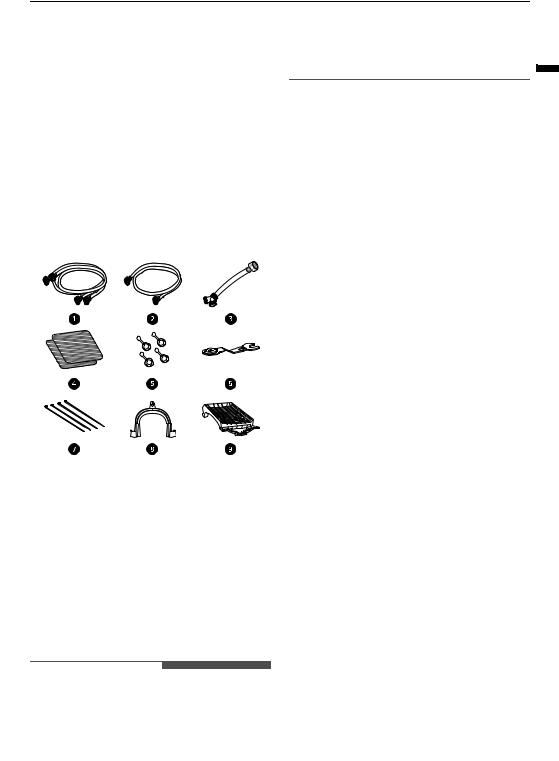
Accessories
aHot and Cold Water Hoses (for Washer)
bCold Water Hose (for Dryer)
cConnecting Supply Hose
dNon-skid Pads
eHole Caps
fWrench
gTie Straps
hElbow Bracket (for securing drain hose)
iDrying Rack
 WARNING
•For your safety and for extended product life, use only authorized components. The manufacturer is not responsible for product

14 INSTALLATION
Specifications
Model |
WK22**S6 |
|
|
|
|
Power supply |
120 V~ 60 Hz |
|
|
|
|
Dimensions (Width X Depth X Height) |
700 mm X 770 mm X 1890 mm |
|
|
|
|
Product weight |
142 kg |
|
|
|
|
Max. capacity |
Washing : 22 kg |
|
Drying : 11 kg (Dry Clothes) / 22 kg (Wet Clothes) |
||
|
||
|
|
|
Maximum Power |
1320 W (washing) / 400 W (drying) |
|
|
|
|
Permissible Inlet Water pressure |
50 KPa ~ 800 KPa (0.5~8.0 kgf/cm²) |
|
|
|
|
Gas Requirements |
NG: 10.2 - 26.7 cm WC |
|
LP: 20.4 - 33.1 cm WC |
||
|
||
|
|
INSTALLATION 15
Installation Place Requirements
Before installing the appliance, check the following information to make sure that the appliance should be installed in a correct place.
Flooring
•To minimize noise and vibration, install the washer on a level, solidly constructed floor capable of supporting the appliance without flexing or bouncing.
•The appliance must be installed on firm flooring to minimize vibration during the spin cycle. Concrete flooring is best, but a wood floor is sufficient, provided it is built to FHA standards.
•The floor under the appliance must not slope more than 2.5 cm from front to back or side to side.
•Installing on carpeting and soft tile surfaces is not recommended.
•Never install the appliance on a platform or weakly supported structure.
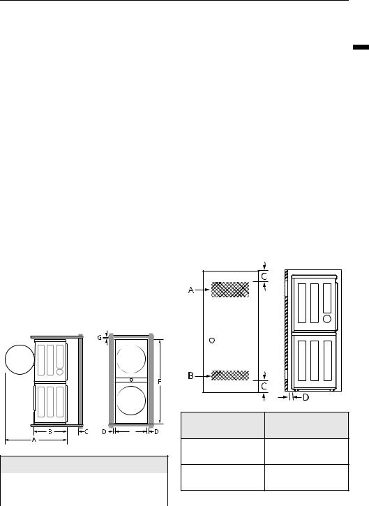
|
Dimensions and Clearances |
|
|
|
|
C |
10 cm |
|
|
|
|
D |
2.5 cm |
|
|
|
|
E |
70 cm |
|
|
|
|
F |
189 cm |
|
|
|
|
G |
2.5 cm |
|
|
|
|
Clearances
The following clearances are recommended for the appliance.
•Additional clearances should be considered for ease of installation and servicing.
•Additional clearances should be considered on all sides of the appliance to reduce noise transfer.
Installation spacing for Recessed Area or Closet Installation
Floor Installation
To ensure sufficient clearance for water inlet hoses, drain hose and airflow, allow minimum clearances of at least 2.5 cm at the sides and 10 cm behind the appliance. Be sure to allow for wall, door, or floor moldings that may increase the required clearances.
E |
Dimensions and Clearances
A |
139.6 cm |
|
|
B |
77 cm |
|
|
Description |
Dimension/ |
|
Clearance |
||
|
||
A: Upper Ventilation |
310 cm2 |
|
Opening |
|
B: Lower Ventilation |
155 cm2 |
Opening |
|
<![endif]>ENGLISH

16 INSTALLATION
Description |
Dimension/ |
|
Clearance |
||
|
||
|
|
|
C: Distance to |
7.6 cm |
|
Ventilation Opening |
|
|
|
|
|
D: Front Clearance |
10 cm |
|
|
|
Closet Ventilation Requirements
Closets with doors must have both an upper and lower vent to prevent heat and moisture buildup in the closet. One upper vent opening with a
minimum opening of 310 cm2 must be installed no lower than 6 feet above the floor. One lower vent
opening with a minimum opening of 155 cm2 must be installed no more than one foot above the floor. Install vent grills in the door or cut down the door at the top and bottom to form openings. Louvered doors with equivalent ventilation openings are also acceptable.
NOTE
•There should be at least a little space around the appliance (or any other appliance) to eliminate the transfer of vibration from one appliance to another. If there is enough vibration, it could cause appliances to make noise or come into contact, causing paint damage and further increasing noise.
•No other fuel-burning appliance can be installed in the same closet as an appliance.
contribute to excessive vibration and unbalance, errors and malfunction.
•To reduce vibration, we recommend placing at least 15 mm thickness of rubber caps a under each adjusting foot of the appliance, secured to at least two floor beams with screws.
•If possible, install the appliance in one of the corners of the room, where the floor is more stable.
•Fit the rubber cups to reduce vibration.
 CAUTION
•If the appliance is installed on the unstable floor (e.g. wooden floor), the warranty does not cover any damages and cost occurred due to the installation on the unstable floor.
NOTE
•You can purchase rubber cups (part No. 4620ER4002B) from the LG service centre.
Wooden Floors (Suspended Floors)
When installing the appliance on wooden floors, use rubber cups to reduce excessive vibration and unbalance. Timber or suspended type flooring may
Electrical Connection
•Do not use an extension cord or double adapter.
•Always unplug the appliance and turn off the water supply after use.
•Connect the appliance to an earthed socket in accordance with current wiring regulations.
•The appliance must be positioned so that the plug is easily accessible.
•Power outlet must be within 1 meter of either side of the appliance.
INSTALLATION 17
 WARNING
•Repairs to the appliance must only be carried out by qualified personnel. Repairs carried out by inexperienced persons may cause injury or serious malfunctioning. Contact your local authorised LG repairer.
•The power plug must be plugged into an appropriate outlet socket that is installed and grounded/earthed in accordance with all local codes and ordinances.
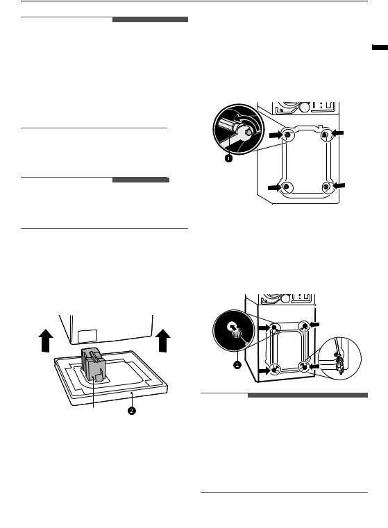
Removing the Transit Bolt Assemblies
To prevent the appliance from severe vibration and breakage, remove transit bolts and retainers.
1 Starting with the bottom two transit bolts a, use the spanner (included) to fully loosen all transit bolts by turning them counterclockwise.
Unpacking the Appliance
 WARNING
•When installing this appliance, take adequate measures to protect yourself, e.g. by wearing protective gloves.
Lifting the Appliance Off the
Foam Base
2 Remove the bolt assemblies by wiggling them slightly while pulling them out.
3 Install the hole caps.
* This feature may vary depending on the model |
• Locate the hole caps b included in the |
purchased. |
accessory pack or attached on the back. |
After removing the carton and shipping material, |
|
lift the appliance off the foam base. |
|
 *
*
•Make sure the tub support a* comes off with the base and is not stuck to the bottom of the appliance.
•If you must lay the appliance down to remove the carton base b, always protect the side of the appliance and lay it carefully on its side. Do not lay the appliance on its front or back.
NOTE
•Save the transit bolts and retainers for future use.
•To prevent damage to the appliance during transport:
-Reinstall the transit bolts.
-Secure the power cord to the back of the appliance.
<![endif]>ENGLISH
18 INSTALLATION
Connecting Electric Dryer
 WARNING
•To reduce the risk of fire or explosion, electric shock, property damage, injury to persons, or death when using this appliance, fulfill the following requirements.
Electrical Requirements for Electric Models Only
 WARNING
•The wiring and grounding must conform to the latest edition of the National Electrical Code, ANSI/NFPA 70 and all applicable local regulations. Please contact a qualified electrician to check your home’s wiring and fuses to ensure that your home has adequate electrical power to operate the dryer.
•This dryer must be connected to a grounded metal, permanent wiring system, or an equipment-grounding conductor must be run with the circuit conductors and connected to the equipment-grounding terminal or lead on the dryer.
•The dryer has its own terminal block that must be connected to a separate 240 VAC, 60-Hertz, single-phase circuit, fused at 30 amperes (the circuit must be fused on both sides of the line). ELECTRICAL SERVICE FOR THE DRYER SHOULD BE OF THE MAXIMUM RATE VOLTAGE LISTED ON THE NAMEPLATE. DO NOT CONNECT THE DRYER TO 110-, 115-, OR 120-VOLT CIRCUIT.
•If the branch circuit to dryer is 4.5 m or less in length, use UL (Underwriters Laboratories) listed No.-10 AWG wire (copper wire only), or as required by local codes. If over 4.5 m, use ULlisted No.-8 AWG wire (copper wire only), or as required by local codes. Allow sufficient slack in wiring so the dryer can be moved from its normal location when necessary.
•The power cord (pigtail) connection between the wall receptacle and the dryer terminal block IS NOT supplied with the dryer. Type of pigtail and gauge of wire must conform to local codes and with instructions on the following pages.
•Do not modify the plug and internal wire provided with the dryer.
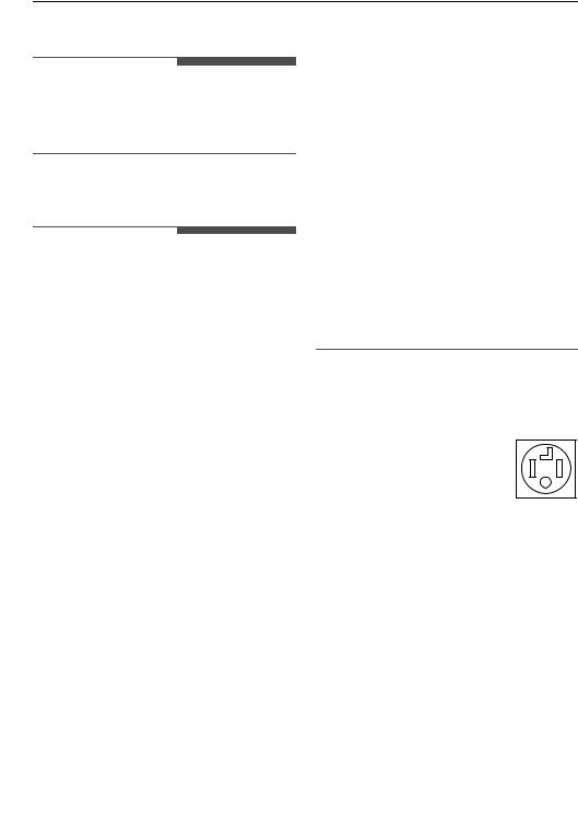
•The dryer should be connected to a 4-hole outlet.
•If the plug does not fit the outlet, a proper outlet will need to be installed by a qualified electrician.
•Connect the power cord to the terminal block. Each colored wire should be connected to the same color screw. Wire color indicated on manual is connected to the same color screw in the block.
•Grounding through the neutral conductor is prohibited for: (1) new branch-circuit installations and (2) areas where local codes prohibit grounding through the neutral conductor.
•This dryer is supplied with the neutral wire grounded. This white ground wire MUST BE MOVED to the neutral terminal when a 4-wire cord is to be used, or where grounding through the neutral conductor is prohibited.
Four-Wire Power Cord
• A UL-listed strain relief is required.
•Use a 30-amp, 240-volt, 4-wire, UL-listed power cord with #10 AWG-minimum copper conductor and closed loop or forked terminals with upturned ends.
1Remove the terminal block access cover on the upper back of the appliance.
2Install UL-listed strain relief into the power cord through-hole.
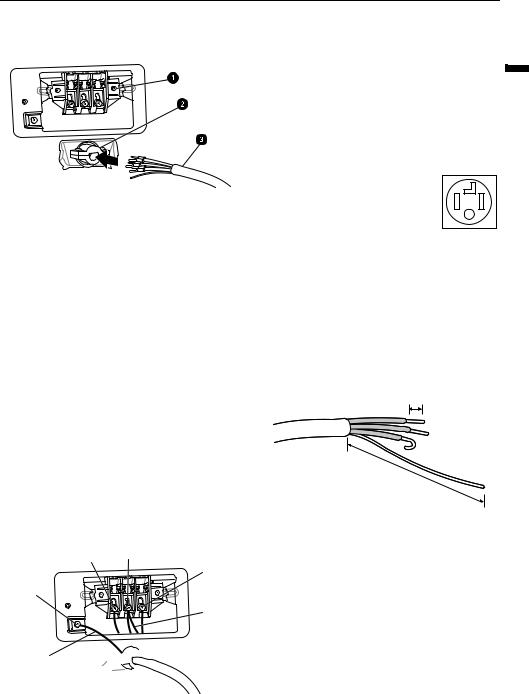
INSTALLATION 19
3 Thread a 30-amp, 240-volt, 4-wire, UL-listed power cord with #10 AWG-minimum copper conductor through the strain relief.
bHot Leads of Power Cord (Black and Red)
cNeutral Wire (White)
dPower Cord Ground Wire
eGround Screw (green)
aTerminal Block
bUL-Listed Strain Relief
cUL-Listed 4-Wire Power Cord
4 Transfer the appliance's ground wire from behind the green ground screw to the center screw of the terminal block.
5 Attach the two hot leads (black and red) of the power cord to the outer terminal block screws.
6 Attach the neutral (white) wire to the center screw of the terminal block
7 Attach the power cord ground wire to the green ground screw.
Four-Wire Direct Wire
• A UL-listed strain relief is required.
•Use UL-listed 4-wire #10 AWG minimum copper conductor cable. Allow at least 1.5 m of wire to allow for removal and reinstallation of the dryer.
1Remove 12.7 cm of the outer covering from the wire and remove 12.7 cm of insulation from the ground wire. Cut off approximately 3.8 cm from the other three wires and strip 2.5 cm insulation from each wire. Bend the ends of the three shorter wires into a hook shape.
1’’ (2.5 cm)
a
5’’ (12.7 cm)
8 Tighten all screws securely.
a Ground Wire
9 Reinstall the terminal block access cover.
b |
c |
2 |
Remove the terminal block access cover on the |
|
b |
||||
|
|
upper back of the appliance. |
||
e |
|
3 |
|
|
|
a |
Install UL-listed strain relief into the power |
||
|
|
|
cord through-hole. |
d

<![endif]>ENGLISH
a White Wire moved from Ground Screw
20 INSTALLATION
4 Thread the 4-wire #10 AWG minimum copper power cable prepared in step 1 through the strain relief.
a
b
c
aTerminal Block
bUL-Listed Strain Relief
cUL-Listed 4-Wire Power Cord
5 Transfer the appliance's ground wire from behind the green ground screw to the center of the terminal block.
6 Attach the two hot leads (black and red) of the power cord to the outer terminal block screws.
7 Attach the neutral (white) wire to the center screw of the terminal block.
8 Attach the power cord ground wire to the green ground screw.
9
10Reinstall the terminal block access cover.
b c
b
e
a
d

aWhite Wire moved from Ground Screw
bHot Leads of Power Cord (Black and Red)
cNeutral Wire (White)
dPower Cord Ground Wire
eGround Screw (green)
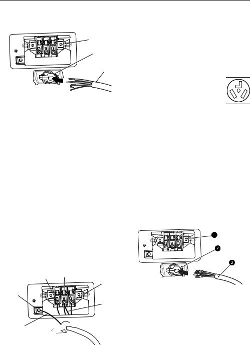
Three-Wire Power Cord
• A 3-wire connection is NOT permitted on new construction after January 1, 1996.
•A UL-listed strain relief is required.
•Use a 30-amp, 240-volt, 3-wire, UL-listed power cord with #10 AWG-minimum copper conductor and closed loop or forked terminals with upturned ends.
1Remove the terminal block access cover on the upper back of the appliance.
2Install the UL-listed strain relief into the power cord through-hole.
3Thread a 30-amp, 240 volt, 3-wire, UL-listed power cord with #10 AWG-minimum copper conductor through the strain relief.
aTerminal Block
bUL-Listed Strain Relief
cUL-Listed 3-Wire Power Cord
4 Attach the two hot leads (black and red) of the power cord to the outer terminal block screws.
|
|
INSTALLATION 21 |
|
5 |
Attach the neutral (white) wire to the center |
Bend the ends of the three wires into a hook |
|
|
terminal block screw. |
shape. |
|
|
|
1’’ (2.5 cm) |
|
6 |
Connect the external ground (if required by |
|
|
|
local codes) to the green ground screw. |
|
|
7 |
Tighten all screws securely. |
2 Remove the terminal block access cover on the |
|
|
|
||
8 |
Reinstall the terminal block access cover. |
upper back of the appliance. |
|
3 Install UL-listed strain relief into the power |
|||
|
|
||
|
|
cord through-hole. |
|
|
|
4 Thread the 3-wire, #10 AWG minimum copper |
|
|
|
conductor power cable prepared in step 1 |
|
|
|
through the strain relief. |
<![endif]>ENGLISH
aWhite Wire from Dryer harness
bHot Leads of Power Cord (Black and Red)
cNeutral Wire (White)
dExternal Ground Wire (If required by local codes)
eGround Screw (green)
Three-Wire Direct Wire
• A 3-wire connection is NOT permitted on new construction after January 1, 1996.
•A UL-listed strain relief is required.
•Use UL-listed 3-wire, #10 AWG minimum copper conductor cable. Allow at least 1.5 m length to allow for removal and installation of dryer.
1Remove 8.9 cm of the outer covering from the wire. Strip 2.5 cm insulation from each wire.
aTerminal block
bUL-listed strain relief
cUL-listed 3-wire power cord
5 Attach the two hot leads (black and red) of the power cord to the outer terminal block screws.
6 Attach the neutral (white) wire to the center terminal block screw.
7 Connect the external ground (if required by local codes) to the green ground screw.
8 Tighten all screws securely.
22 INSTALLATION
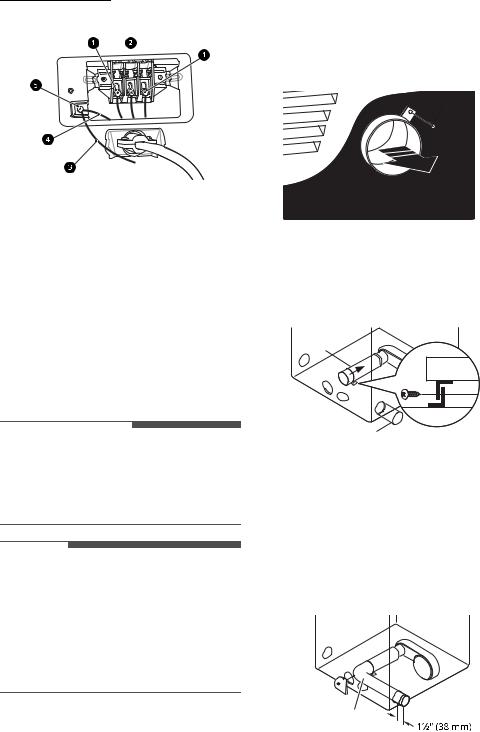
9 Reinstall the terminal block access cover.
aHot lead (black and red)
bNeutral wire (white)
cExternal ground wire (if required by local codes)
dWire from the appliance harness
eGround screw (green)
Installing the Vent Kit of Dryer
The appliance is configured to vent to the rear. It can also vent to the side.
Side Venting
1 Remove the rear exhust duct retaining screw a and pull out the exhaust duct b.
a
b
2 Press the tabs on the knockout cand carefully remove the knockout for the desired vent opening. (Right-side venting is not available on gas models.) Press the adapter duct donto the blower housing and secure to the base of the dryer as shown.
d
 WARNING
•Use long-sleeved gloves and safety glasses.
•Use a heavy metal vent.
•Do not use plastic or thin foil ducts.
•Clean old ducts before installing the appliance.
NOTE
•An adapter kit, part number 383EEL9001B, may be purchased from your LG retailer. This kit contains duct components necessary to change the appliance vent location.
•Right-side venting is not available on gas models.
•Bottom venting is not available on stacked or integrated stacked models.
c
3 Preassemble a 10 cm elbow e to the next 10 cm duct section, and secure all joints with duct tape. Be sure that the male end of the elbow faces AWAY from the dryer. Insert the elbow/ duct assembly through the side opening and press it onto the adapter duct. Secure it in place with duct tape. Be sure that the male end of the duct protrudes 3.8 cm to connect the remaining ductwork. Attach the cover plate f to the back of the dryer with the included screw.
f


e
INSTALLATION 23
Venting the Dryer
 WARNING
•Gas dryers MUST exhaust to the outdoors.
•DO NOT use sheet metal screws or other fasteners which extend into the duct that could catch lint and reduce the efficiency of the exhaust system. Secure all joints with duct tape.
•To reduce the risk of fire, combustion, or accumulation of combustible gases, DO NOT exhaust dryer air into an enclosed and unventilated area, such as an attic, wall, ceiling, crawl space, chimney, gas vent, or concealed space of a building.
•To reduce the risk of fire, DO NOT exhaust the dryer with plastic or thin foil ducting.
•Do not exceed the recommended duct length limitations noted in the chart. Failure to follow these instructions may result in extended drying times, fire or death.
•Do not crush or collapse ductwork.
•Do not allow ductwork to rest on or contact sharp objects.
Ductwork
•If connecting to existing ductwork, make sure it is suitable and clean before installing the dryer.
•Venting must conform to local building codes.
•Use only 10 cm rigid, semi-rigid or flexible metal ductwork inside the dryer cabinet and for venting outside.
•The exhaust duct must be 10 cm in diameter with no obstructions. The exhaust duct should be kept as short as possible. Make sure to clean any old ducts before installing your new dryer.
•Rigid, semi-rigid or flexible metal ducting is recommended for use between the dryer and the wall. All non-rigid metal transition duct must be UL-listed. Use of other materials for transition duct could affect drying time.
•Ductwork is not provided with the dryer. You should obtain the necessary ductwork locally. The vent hood should have hinged dampers to prevent backdraft when the dryer is not in use.
•The total length of flexible metal duct must not exceed 2.4 m.
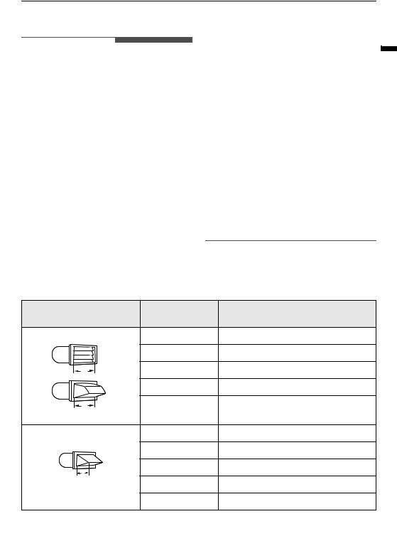
Wall Cap Type |
Number of 90° |
Maximum length of 10 cm diameter rigid |
|
Elbows |
metal duct |
||
|
|||
Recommended |
0 |
19.8 m |
|
|
1 |
16.8 m |
|
a |
2 |
14.3 m |
|
|
3 |
11.0 m |
|
a |
4 |
8.5 m |
|
a: 4 ‘’ (10 cm) |
|
|
|
Use for only short run |
0 |
16.8 m |
|
installations |
1 |
14.3 m |
|
|
|||
b |
2 |
12.5 m |
|
|
|
||
b: 2 1/2 ‘’ (6.4 cm) |
3 |
9.1 m |
|
|
4 |
6.7 m |
<![endif]>ENGLISH

24 INSTALLATION
NOTE
• Deduct 1.8 m for each additional elbow. Do not use more than four 90° elbows.
Routing and Connecting Ductwork
Follow the guidelines below to maximize drying performance and reduce lint buildup and condensation in the ductwork. Ductwork and fittings are NOT included and must be purchased separately.
•Use 10 cm diameter rigid, semi-rigid or flexible metal ductwork.
•The exhaust duct run should be as short as possible.
•Use as few elbow joints as possible.
•The male end of each section of exhaust duct must point away from the dryer.
•Use duct tape on all duct joints.
•Insulate ductwork that runs through unheated areas in order to reduce condensation and lint buildup on duct surfaces.
•Incorrect or inadequate exhaust systems are not covered by the dryer warranty. Dryer failures or service required because of such exhaust systems will not be covered by the dryer warranty.
Correct Venting |
Incorrect Venting |
Connecting Gas Dryer
 WARNING
•To reduce the risk of fire or explosion, electric shock, property damage, injury to persons, or death when using this appliance, follow requirements including the following:
Electrical Requirments for Gas Models
 WARNING
•This dryer is equipped with a three-prong grounding plug for protection against shock hazard and should be plugged directly into a properly grounded three-prong receptacle. Do not cut or remove the grounding prong from this plug.
•Do not, under any circumstances, cut or remove the third (ground) prong from the power cord.
•For personal safety, this dryer must be properly grounded.
•This dryer must be plugged into a 120-VAC, 60Hz. grounded outlet protected by a 15-ampere fuse or circuit breaker.
•Where a standard 2-prong wall outlet is encountered, it is your personal responsibility and obligation to have it replaced with a properly grounded 3-prong wall outlet.
Gas Supply Requirements
 WARNING
•DO NOT attempt any disassembly of the dryer; disassembly requires the attention and tools of an authorized and qualified service technician or company.
Loading...