


<![endif]>ENGLISH
INSTALLATION MANUAL
AIR
CONDITIONER
Please read this installation manual completely before installing the product. Installation work must be performed in accordance with the national wiring standards by authorized personnel only.
Please retain this installation manual for future reference after reading it thoroughly.
MFL67448518 |
www.lg.com |
Rev.00_101719 |
Copyright © 2014 - 2019 LG Electronics Inc. All Rights Reserved. |

<![endif]>ENGLISH
2 |
TIPS FOR SAVING ENERGY |
|
|
|
|
TIPS FOR SAVING ENERGY
Here are some tips that will help you minimize the power consumption when you use the air conditioner. You can use your air conditioner more efficiently by referring to the instructions below:
•Do not cool excessively indoors. This may be harmful to your health and may consume more electricity.
•Block sunlight with blinds or curtains while you are operating the air conditioner.
•Keep doors or windows closed tightly while you are operating the air conditioner.
•Adjust the direction of the air flow vertically or horizontally to circulate indoor air.
•Speed up the fan to cool or warm indoor air quickly, in a short period of time.
•Open windows regularly for ventilation as the indoor air quality may deteriorate if the air conditioner is used for many hours.
•Clean the air filter once every 2 weeks. Dust and impurities collected in the air filter may block the air flow or weaken the cooling / dehumidifying functions.
For your records
Staple your receipt to this page in case you need it to prove the date of purchase or for warranty purposes. Write the model number and the serial number here:
Model number :
Serial number :
You can find them labeled on the side of each unit.
Dealer’s name :
Date of purchase :

SAFETY INSTRUCTIONS 3
SAFETY INSTRUCTIONS
The following safety guidelines are intended to prevent unforeseen risks or damage from unsafe or incorrect operation of the appliance.
The guidelines are separated into ‘WARNING’ and ‘CAUTION’ as described below.
This symbol is displayed to indicate matters and operations that can cause risk.
!Read the part with this symbol carefully and follow the instructions in order to avoid risk.
!WARNING
This indicates that the failure to follow the instructions can cause serious injury or death.
! CAUTION
This indicates that the failure to follow the instructions can cause the minor injury or damage to the product.
! WARNING
•Installation or repairs made by unqualified persons can result in hazards to you and others.
•Installation work must be performed in accordance with the National Electric Code by qualified and authorized personnel only.
•The information contained in the manual is intended for use by a qualified service technician familiar with safety procedures and equipped with the proper tools and test instruments.
•Failure to carefully read and follow all instructions in this manual can result in equipment malfunction, property damage, personal injury and/or death.
Installation
•Always perform grounding. Otherwise, it may cause electrical shock.
•Don’t use a power cord, a plug or a loose socket which is damaged. Otherwise, it may cause a fire or electrical shock.
•For installation of the product, always contact the service center or a professional installation agency. Otherwise, it may cause a fire, electrical shock, explosion or injury.
•Securely attach the electrical part cover to the indoor unit and the service panel to the outdoor unit.
If the electrical part cover of the indoor unit and the service panel of the outdoor unit are not attached securely, it could result in a fire or electric shock due to dust, water, etc.
•Always install an air leakage breaker and a dedicated switching board. No installation may cause a fire and electrical shock.
•Do not keep or use flammable gases or combustibles near the air conditioner. Otherwise, it may cause a fire or the failure of product.
•Ensure that an installation frame of the outdoor unit is not damaged due to use for a long time. It may cause injury or an accident.
•Do not disassemble or repair the product randomly. It will cause a fire or electrical shock.
•Use a vacuum pump or Inert (nitrogen) gas when doing leakage test or air purge. Do not compress air or Oxygen and do not use Flammable gases. Otherwise, it may cause fire or explosion.
There is the risk of death, injury, fire or explosion.
•Do not install the product at a place that there is concern of falling down. Otherwise, it may result in personal injury.
•Use caution when unpacking and installing. Sharp edges may cause injury.
<![endif]>ENGLISH

|
4 |
SAFETY INSTRUCTIONS |
|
| <![if ! IE]> <![endif]>ENGLISH |
|
||
• Do not turn on the breaker or power under condition that front panel, cabinet, top cover, control box |
|||
|
|||
|
cover are removed or opened. Otherwise, it may cause fire, electric shock, explosion or death. |
||
|
Operation |
||
|
• Do not share the outlet with other appliances. It will cause an electric shock or a fire due to |
||
|
heat generation. |
||
|
• Do not use the damaged power cord. Otherwise, it may cause a fire or electrical shock. |
||
|
• Do not modify or extend the power cord randomly. Otherwise, it may cause a fire or electrical |
||
|
shock. |
||
|
• Take care so that the power cord may not be pulled during operation. Otherwise, it may cause |
||
|
a fire or electrical shock. |
||
|
• Unplug the unit if strange sounds, smell, or smoke comes from it. Otherwise, it may cause |
||
|
electrical shock or a fire. |
||
|
• Keep the flames away. Otherwise, it may cause a fire. |
||
|
• Take the power plug out if necessary, holding the head of the plug and do not touch it with wet |
||
|
hands. Otherwise, it may cause a fire or electrical shock. |
||
|
• Do not use the power cord near the heating tools. Otherwise, it may cause a fire and electrical |
||
|
shock. |
||
|
• Do not open the suction inlet of the indoor/outdoor unit during operation. |
||
|
Otherwise, it may electrical shock and failure. |
||
|
• Do not allow water to run into electrical parts. Otherwise, it may cause the failure of machine or |
||
|
electrical shock. |
||
|
• Hold the plug by the head when taking it out. It may cause electric shock and damage. |
||
|
• Never touch the metal parts of the unit when removing the filter. They are sharp and may |
||
|
cause injury. |
||
|
• Do not step on the indoor/outdoor unit and do not put anything on it. It may cause an injury |
||
|
through dropping of the unit or falling down. |
||
|
• Do not place a heavy object on the power cord. Otherwise, it may cause a fire or electrical shock. |
||
|
• When the product is submerged into water, always contact the service center. Otherwise, it |
||
|
may cause a fire or electrical shock. |
||
|
• Take care so that children may not step on the outdoor unit. Otherwise, children may be |
||
|
seriously injured due to falling down. |
||
! CAUTION
Installation
• Install the drain hose to ensure that drain can be securely done. Otherwise, it may cause water leakage.
• Install the product so that the noise or hot wind from the outdoor unit may not cause any damage to the neighbors. Otherwise, it may cause dispute with the neighbors.
• Always inspect gas leakage after the installation and repair of product. Otherwise, it may cause the failure of product.
• Keep level parallel in installing the product. Otherwise, it may cause vibration or water leakage.
Operation
•Avoid excessive cooling and perform ventilation sometimes. Otherwise, it may do harm to your health.
•Use a soft cloth to clean. Do not use wax, thinner, or a strong detergent. The appearance of the air conditioner may deteriorate, change color, or develop surface flaws.
•Do not use an appliance for special purposes such as preserving animals vegetables, precision machine, or art articles. Otherwise, it may damage your properties.
•Do not place obstacles around the flow inlet or outlet. Otherwise, it may cause the failure of appliance or an accident.

TABLE OF CONTENTS |
5 |
|
TABLE OF CONTENTS
2TIPS FOR SAVING ENERGY
3SAFETY INSTRUCTIONS
6INSTALLATION OF OUTDOOR UNIT
9Night Silent Operation setting
10 WIRING CONNECTION
10Electrical Wiring
11Connecting Cables between Indoor Unit and Outdoor Unit
13Connecting the cable to Outdoor Unit
14CONNECTING PIPES
14Preparation of Piping
15Connecting the pipes to the Outdoor unit
16Forming the piping
17LEAKAGE TEST AND EVACUATION
17 Preparation
17Leakage test
18Evacuation
19TEST RUNNING
21 FUNCTION
21Forced Cooling Operation
22SELF-DIAGNOSIS FUNCTION
22 Error Indicator (Outdoor)
24 INSTALLATION GUIDE AT THE SEASIDE
<![endif]>ENGLISH
<![endif]>ENGLISH
6 |
INSTALLATION OF OUTDOOR UNIT |
|
|
|
|
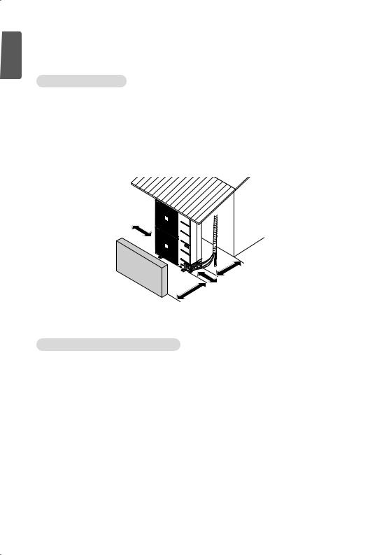
INSTALLATION OF OUTDOOR UNIT
Installation Places
-If an awning is built over the unit to prevent direct sunlight or rain exposure, make sure that heat radiation from the condenser is not restricted.
-Ensure that the spaces indicated by arrows around front, back and side of the unit.
-Do not place animals and plants in the path of the warm air.
-Take the air conditioner weight into account and select a place where noise and vibration are minimum.
-Select a place so that the warm air and noise from the air conditioner do not disturb neighbors.
|
Sunroof |
Unit : mm |
|
|
|
More than |
|
|
300 mm |
|
|
Fence or |
|
More than |
|
300 mm |
|
|
|
|
obstacles |
|
|
More than 600 mm
More than 700 mm
Piping length and the elevation
Free Joint Single Outdoor
|
|
Pipe Size |
Length A (m) |
Elevation B (m) |
Additional |
||||
MODEL |
CAPACITY |
|
|
|
|
|
|
Refrigerant |
|
Gas |
Liquid |
Standard |
Max. |
Standard |
Max. |
||||
|
|
(g/m) |
|||||||
|
|
|
|
|
|
|
|
|
|
AUUQ18GH2 |
5 kW |
Ø 12.7(1/2) |
Ø 6.35(1/4) |
5 |
30 |
5 |
15 |
20 |
|
|
|
|
|
|
|
|
|
|
|
AUUQ24GH2 |
7 kW |
Ø 15.88(5/8) |
Ø 9.52(3/8) |
5 |
50 |
5 |
30 |
20 |
|
|
|
|
|
|
|
|
|
|
|
AUUQ36GH2 |
10 kW |
Ø 15.88(5/8) |
Ø 9.52(3/8) |
5 |
50 |
5 |
30 |
20 |
|
|
|
|
|
|
|
|
|
|
|
AUUQ48GH2 |
13.4 kW |
Ø 15.88(5/8) |
Ø 9.52(3/8) |
5 |
50 |
5 |
30 |
20 |
|
|
|
|
|
|
|
|
|
|
|
AUUQ54GH2 |
15.8 kW |
Ø 19.05(3/4) |
Ø 9.52(3/8) |
5 |
50 |
5 |
30 |
20 |
|
|
|
|
|
|
|
|
|
|
|

|
|
|
|
|
INSTALLATION OF OUTDOOR UNIT |
7 |
|||||
Ceiling Cassette |
|
|
|
|
|
|
|
|
|
||
|
|
|
|
|
|
|
|
|
|
||
|
|
|
|
|
|
|
|
|
|
|
|
|
|
|
Pipe Size |
Length A (m) |
Elevation B (m) |
Additional |
|
||||
MODEL |
|
CAPACITY |
|
|
|
|
|
|
Refrigerant |
||
|
Gas |
Liquid |
Standard |
Max. |
Standard |
Max. |
|||||
|
|
|
(g/m) |
|
|||||||
|
|
|
|
|
|
|
|
|
|
|
|
ATUQ18GPLE5 |
|
5 kW |
Ø 12.7(1/2) |
Ø 6.35(1/4) |
5 |
30 |
5 |
15 |
20 |
|
|
ATUQ18GQLE5 |
|
|
|
||||||||
|
|
|
|
|
|
|
|
|
|
|
|
|
|
|
|
|
|
|
|
|
|
|
|
ATUQ24GPLE5 |
|
7 kW |
Ø 15.88(5/8) |
Ø 9.52(3/8) |
5 |
50 |
5 |
30 |
20 |
|
|
ATUQ24GQLE5 |
|
|
|
||||||||
|
|
|
|
|
|
|
|
|
|
|
|
|
|
|
|
|
|
|
|
|
|
|
|
ATUQ36GPLE5 |
|
10 kW |
Ø 15.88(5/8) |
Ø 9.52(3/8) |
5 |
50 |
5 |
30 |
20 |
|
|
|
|
|
|
|
|
|
|
|
|
|
|
ATUQ48GMLE5 |
|
13.4 kW |
Ø 15.88(5/8) |
Ø 9.52(3/8) |
5 |
50 |
5 |
30 |
20 |
|
|
|
|
|
|
|
|
|
|
|
|
|
|
ATUQ54GMLE5 |
|
15.8 kW |
Ø 19.05(3/4) |
Ø 9.52(3/8) |
5 |
50 |
5 |
30 |
20 |
|
|
|
|
|
|
|
|
|
|
|
|
|
|
Ceiling Suspended Air conditioner |
|
|
|
|
|
|
|
|
|||
|
|
|
|
|
|
|
|
||||
|
|
|
Pipe Size |
Length A (m) |
Elevation B (m) |
Additional |
|
||||
MODEL |
|
CAPACITY |
|
|
|
|
|
|
Refrigerant |
||
|
Gas |
Liquid |
Standard |
Max. |
Standard |
Max. |
|||||
|
|
|
(g/m) |
|
|||||||
|
|
|
|
|
|
|
|
|
|
|
|
AVUQ18GJLA2 |
|
5 kW |
Ø 12.7(1/2) |
Ø 6.35(1/4) |
5 |
30 |
5 |
15 |
20 |
|
|
|
|
|
|
|
|
|
|
|
|
|
|
AVUQ24GJLA2 |
|
7 kW |
Ø 15.88(5/8) |
Ø 9.52(3/8) |
5 |
50 |
5 |
30 |
20 |
|
|
|
|
|
|
|
|
|
|
|
|
|
|
AVUQ36GKLA2 |
|
10 kW |
Ø 15.88(5/8) |
Ø 9.52(3/8) |
5 |
50 |
5 |
30 |
20 |
|
|
|
|
|
|
|
|
|
|
|
|
|
|
AVUQ48GLLA2 |
|
13.4 kW |
Ø 15.88(5/8) |
Ø 9.52(3/8) |
5 |
50 |
5 |
30 |
20 |
|
|
|
|
|
|
|
|
|
|
|
|
|
|
AVUQ54GLLA2 |
|
15.8 kW |
Ø 19.05(3/4) |
Ø 9.52(3/8) |
5 |
50 |
5 |
30 |
20 |
|
|
|
|
|
|
|
|
|
|
|
|
|
|
Ceiling Concealed Duct |
|
|
|
|
|
|
|
|
|
||
Ceiling Concealed Duct – Low Static |
|
|
|
|
|
|
|
|
|||
|
|
|
|
|
|
|
|
||||
|
|
|
Pipe Size |
Length A (m) |
Elevation B (m) |
Additional |
|
||||
MODEL |
|
CAPACITY |
|
|
|
|
|
|
Refrigerant |
||
|
Gas |
Liquid |
Standard |
Max. |
Standard |
Max. |
|||||
|
|
|
(g/m) |
|
|||||||
|
|
|
|
|
|
|
|
|
|
|
|
ABUQ18GM1A2 |
|
|
|
|
|
|
|
|
|
|
|
ABUQ18GL2A1 |
|
5 kW |
Ø 12.7(1/2) |
Ø 6.35(1/4) |
5 |
30 |
5 |
15 |
20 |
|
|
ABUQ18GL2R1 |
|
|
|
|
|
|
|
|
|
|
|
ABUQ24GM1A2 |
|
7 kW |
Ø 15.88(5/8) |
Ø 9.52(3/8) |
5 |
50 |
5 |
30 |
20 |
|
|
ABUQ24GL3A1 |
|
|
|
||||||||
|
|
|
|
|
|
|
|
|
|
|
|
|
|
|
|
|
|
|
|
|
|
|
|
ABUQ36GM2A2 |
|
10 kW |
Ø 15.88(5/8) |
Ø 9.52(3/8) |
5 |
50 |
5 |
30 |
20 |
|
|
|
|
|
|
|
|
|
|
|
|
|
|
ABUQ48GM3A2 |
|
13.4 kW |
Ø 15.88(5/8) |
Ø 9.52(3/8) |
5 |
50 |
5 |
30 |
20 |
|
|
|
|
|
|
|
|
|
|
|
|
|
|
ABUQ54GM3A2 |
|
15.8 kW |
Ø 19.05(3/4) |
Ø 9.52(3/8) |
5 |
50 |
5 |
30 |
20 |
|
|
|
|
|
|
|
|
|
|
|
|
|
|
Floor Standing Air Conditioner |
|
|
|
|
|
|
|
|
|||
|
|
|
|
|
|
|
|
||||
|
|
|
Pipe Size |
Length A (m) |
Elevation B (m) |
Additional |
|
||||
MODEL |
|
CAPACITY |
|
|
|
|
|
|
Refrigerant |
||
|
Gas |
Liquid |
Standard |
Max. |
Standard |
Max. |
|||||
|
|
|
(g/m) |
|
|||||||
|
|
|
|
|
|
|
|
|
|
|
|
APUQ36GRA2 |
|
10 kW |
Ø 15.88(5/8) |
Ø 9.52(3/8) |
5 |
50 |
5 |
30 |
20 |
|
|
|
|
|
|
|
|
|
|
|
|
|
|
APUQ48GTA2 |
|
13.4 kW |
Ø 15.88(5/8) |
Ø 9.52(3/8) |
5 |
50 |
5 |
30 |
20 |
|
|
|
|
|
|
|
|
|
|
|
|
|
|
<![endif]>ENGLISH

<![endif]>ENGLISH
8 INSTALLATION OF OUTDOOR UNIT
If installed tube is shorter than 15 m, additional charging is not necessary. Additional Refrigerant = (A -15) x Additional refrigerant (g)
Indoor unit
Outdoor unit
A
B |
Outdoor unit |
|
A |
Indoor unit |
B |
|
!CAUTION
•Capacity is based on standard length and maximum allowance length is on the basis of reliability.
•Improper refrigerant charge may result in abnormal cycle.

INSTALLATION OF OUTDOOR UNIT |
9 |
|
Night Silent Operation setting
-Open the Side panel or Top Cover of outdoor unit.
-Set the SW1 or DIP-SW01D.
Step 1
6
Step 2
6
SW1 |
DIP–SW01D |
|
6 |
AUUQ36GH2 |
AUUQ48GH2 |
/ AUUQ54GH2 |
ATUQ36GPLE5 |
ATUQ48GMLE5 |
/ ATUQ54GMLE5 |
ABUQ36GM2A2 |
ABUQ48GM3A2 |
/ ABUQ54GM3A2 |
AVUQ36GKLA2 |
AVUQ48GLLA2 / AVUQ54GLLA2 |
|
APUQ36GRA2 |
APUQ48GTA2 |
|
-Close the Side panel or Top Cover.
!WARNING
•When you set the DIP switch, you should turn off the circuit breaker or shut the power source of the product down.
!CAUTION
•Unless the applicable DIP switch is set properly, the product may not work.
•If you want to set a specific function, request that the installer sets the DIP switch appropriately during installation.
<![endif]>ENGLISH
 Loading...