

Page 1

EDS94ARNExxxx
13279702
Ä.<ö#ä
L-force Drives
Software Manual
9400
E94AxRNxxxx
9400 regenerative power supply module
Parameter setting
L
Page 2

9400 regenerative power supply module | Parameter setting
Overview of technical documentation for 9400 Servo Drives
Overview of technical documentation for 9400 Servo Drives
Project planning, selecting & ordering Legend:
9400 Hardware Manual Printed documentation
Catalogue / electronic catalogue (DSC - Drive Solution Catalogue) Online documentation
(PDF/Engineer online help)
Mounting & wiring Abbreviations used:
MA for controller BA Operating Instructions
MA for regenerative power supply module KHB Communication Manual
MA for communication module MA Mounting Instructions
MA for extension module SW Software Manual
MA for safety module
MA for accessories
MA for remote maintenance components
Parameter setting
BA for keypad
SW for Lenze »Engineer« software
SW for controller (9400 HighLine/9400 PLC)
SW for regenerative power supply module This documentation
KHB for communication module
SW for extension module
SW for safety module
SW for Lenze technology application
SW for 9400 function library
Configuring & programming
SW for Lenze »L-force Engineer« software
SW for Lenze »PLC Designer« software
SW for controller (9400 HighLine/9400 PLC)
KHB for communication module
SW for extension module
SW for safety module
SW for Lenze technology application
SW for 9400 function library
Commissioning the drive/device
SW for controller
SW for regenerative power supply module This documentation
Chapter "Commissioning
Chapter "Oscilloscope
Chapter "Diagnostics & fault analysis
Remote Maintenance Manual
Establishing the networking
KHB for communication medium used
" ( 12)
" ( 170)
" ( 187)
2 L EDS94ARNExxxx EN 2.3 - 06/2014
Page 3

9400 regenerative power supply module | Parameter setting
Contents
Contents
1 About this documentation . . . . . . . . . . . . . . . . . . . . . . . . . . . . . . . . . . . . . . . . . . . . . . . . . . . . . . . . . 9
1.1 Conventions used
1.2 Terminology used
1.3 Definition of notes used
2 Commissioning
2.1 Short setup
2.1.1 Example circuit
2.1.2 Commissioning with the keypad
2.1.3 Commissioning with the Engineer
2.1.4 Controlling the regenerative power supply module via terminals
2.2 Device replacement
2.3 Filter replacement
3 Regenerative power supply module application
3.1 Parameterising the brake chopper/brake resistor
3.1.1 Setting the voltage threshold for braking operation
3.1.2 Setting the brake chopper mode
3.1.3 Monitoring
. . . . . . . . . . . . . . . . . . . . . . . . . . . . . . . . . . . . . . . . . . . . . . . . . . . . . . . . . . . . . . . . . . . 12
3.1.3.1 Overcurrent protection
3.1.3.2 Ixt utilisation of brake transistor
3.1.3.3 I2t utilisation of brake resistor
3.1.3.4 DC-bus overvoltage
. . . . . . . . . . . . . . . . . . . . . . . . . . . . . . . . . . . . . . . . . . . . . . . . . . . . . . . . . . . . . . . 10
. . . . . . . . . . . . . . . . . . . . . . . . . . . . . . . . . . . . . . . . . . . . . . . . . . . . . . . . . . . . . . . 10
. . . . . . . . . . . . . . . . . . . . . . . . . . . . . . . . . . . . . . . . . . . . . . . . . . . . . . . . . 11
. . . . . . . . . . . . . . . . . . . . . . . . . . . . . . . . . . . . . . . . . . . . . . . . . . . . . . . . . . . . . . . . . . . . . 13
. . . . . . . . . . . . . . . . . . . . . . . . . . . . . . . . . . . . . . . . . . . . . . . . . . . . . . . . . . 13
. . . . . . . . . . . . . . . . . . . . . . . . . . . . . . . . . . . . . . . . . . . . . . . . . . . . . . . . . . . . . 20
. . . . . . . . . . . . . . . . . . . . . . . . . . . . . . . . . . . . . . . . . . . . . . . . . . . . . . . . . . . . . . . 20
. . . . . . . . . . . . . . . . . . . . . . . . . . . . . . . . . . . . . . . . . . . . . . . . . . . . . . . . . . . . . . 25
. . . . . . . . . . . . . . . . . . . . . . . . . . . . . . . . . . . . . . . . . . . . 29
. . . . . . . . . . . . . . . . . . . . . . . . . . . . . . . . . . . . . . . . . . 14
. . . . . . . . . . . . . . . . . . . . . . . . . . . . . . . . . . . . . . . . 15
. . . . . . . . . . . 19
. . . . . . . . . . . . . . . . . . . . . . . . . . . . . . . . . . . . . . 21
. . . . . . . . . . . . . . . . . . . . . . . . . . . . . . . . . 22
. . . . . . . . . . . . . . . . . . . . . . . 24
. . . . . . . . . . . . . . . . . . . . . . . . . . . . . . . . . . . . . . . . . . 24
. . . . . . . . . . . . . . . . . . . . . . . . . . . . . . . . . . . . . . . . . 25
. . . . . . . . . . . . . . . . . . . . . . . . . . . . . . . . 26
. . . . . . . . . . . . . . . . . . . . . . . . . . . . . . . . . . 27
3.2 Signal configuration
3.2.1 Device and line interface
3.2.2 Output ports
3.3 Assignment of the I/O terminals
4 Device interface
4.1 Device commands
4.1.1 Load Lenze setting
4.1.2 Load start parameters
4.1.3 Load route data from the ENP
4.1.4 Activate application
4.1.5 Save selected application
4.1.6 Save start parameters
4.1.7 Delete logbook
4.1.8 Archive log file
4.1.9 Start application
4.1.10 Stop application
. . . . . . . . . . . . . . . . . . . . . . . . . . . . . . . . . . . . . . . . . . . . . . . . . . . . . . . . . . . . . . . . . . . 36
. . . . . . . . . . . . . . . . . . . . . . . . . . . . . . . . . . . . . . . . . . . . . . . . . . . . . . . . . . . . . . . 37
. . . . . . . . . . . . . . . . . . . . . . . . . . . . . . . . . . . . . . . . . . . . . . . . . . . . . . . . . . . . . 30
. . . . . . . . . . . . . . . . . . . . . . . . . . . . . . . . . . . . . . . . . . . . . . . . . 30
. . . . . . . . . . . . . . . . . . . . . . . . . . . . . . . . . . . . . . . . . . . . . . . . . . . . . . . . . . . . 31
. . . . . . . . . . . . . . . . . . . . . . . . . . . . . . . . . . . . . . . . . . . . . . . . . 34
. . . . . . . . . . . . . . . . . . . . . . . . . . . . . . . . . . . . . . . . . . . . . . . . . . . . . . . 39
. . . . . . . . . . . . . . . . . . . . . . . . . . . . . . . . . . . . . . . . . . . . . . . . . . . 40
. . . . . . . . . . . . . . . . . . . . . . . . . . . . . . . . . . . . . . . . . . . . 41
. . . . . . . . . . . . . . . . . . . . . . . . . . . . . . . . . . . . . . . . . . . . . . . . . . . . . 42
. . . . . . . . . . . . . . . . . . . . . . . . . . . . . . . . . . . . . . . . . . . . . . . . 43
. . . . . . . . . . . . . . . . . . . . . . . . . . . . . . . . . . . . . . . . . . . . . . . . . . . . 44
. . . . . . . . . . . . . . . . . . . . . . . . . . . . . . . . . . . . . . . . . . . . . . . . . . . . . . . . . . 46
. . . . . . . . . . . . . . . . . . . . . . . . . . . . . . . . . . . . . . . . . . . . . . . . . . . . . . . . . . . 47
. . . . . . . . . . . . . . . . . . . . . . . . . . . . . . . . . . . . . . . . . . . . . . . . . . . . . . . . . 48
. . . . . . . . . . . . . . . . . . . . . . . . . . . . . . . . . . . . . . . . . . . . . . . . . . . . . . . . . 49
EDS94ARNExxxx EN 2.3 - 06/2014 L 3
Page 4

9400 regenerative power supply module | Parameter setting
Contents
4.1.11 Reset program. . . . . . . . . . . . . . . . . . . . . . . . . . . . . . . . . . . . . . . . . . . . . . . . . . . . . . . . . . . 50
4.1.12 Delete program
4.1.13 Restart program
4.1.14 Reset runtime measurement
4.1.15 Inhibit controller
4.1.16 Enable controller
4.1.17 Reset error
4.1.18 Reset max DC power mot.
4.1.19 Reset max DC power reg.
4.1.20 Reset max. line power reg.
4.1.21 Reset transmitted energy
4.1.22 Reset regenerated energy
4.1.23 CAN on-board: Reset node
4.1.24 CAN module: Reset node
4.1.25 CAN on-board: Pred.Connect.Set
4.1.26 CAN module: Pred.Connect.Set
4.1.27 CAN on-board: Identify node
4.1.28 CAN module: Identify node
4.1.29 Unbind/bind Ethernet module MXI1
4.1.30 Unbind/bind Ethernet module MXI2
4.1.31 Activate parameter sets 1 ... 4
4.1.32 Archive parameter sets 1 ... 4
4.1.33 Format file system
4.1.34 Restore file system
4.1.35 Prepare firmware update
4.1.36 Restart controller
. . . . . . . . . . . . . . . . . . . . . . . . . . . . . . . . . . . . . . . . . . . . . . . . . . . . . . . . . . 51
. . . . . . . . . . . . . . . . . . . . . . . . . . . . . . . . . . . . . . . . . . . . . . . . . . . . . . . . . 52
. . . . . . . . . . . . . . . . . . . . . . . . . . . . . . . . . . . . . . . . . . . . . 53
. . . . . . . . . . . . . . . . . . . . . . . . . . . . . . . . . . . . . . . . . . . . . . . . . . . . . . . . 55
. . . . . . . . . . . . . . . . . . . . . . . . . . . . . . . . . . . . . . . . . . . . . . . . . . . . . . . . 56
. . . . . . . . . . . . . . . . . . . . . . . . . . . . . . . . . . . . . . . . . . . . . . . . . . . . . . . . . . . . . . 57
. . . . . . . . . . . . . . . . . . . . . . . . . . . . . . . . . . . . . . . . . . . . . . . . 58
. . . . . . . . . . . . . . . . . . . . . . . . . . . . . . . . . . . . . . . . . . . . . . . . . 59
. . . . . . . . . . . . . . . . . . . . . . . . . . . . . . . . . . . . . . . . . . . . . . . 60
. . . . . . . . . . . . . . . . . . . . . . . . . . . . . . . . . . . . . . . . . . . . . . . . 61
. . . . . . . . . . . . . . . . . . . . . . . . . . . . . . . . . . . . . . . . . . . . . . . . 62
. . . . . . . . . . . . . . . . . . . . . . . . . . . . . . . . . . . . . . . . . . . . . . . 63
. . . . . . . . . . . . . . . . . . . . . . . . . . . . . . . . . . . . . . . . . . . . . . . . . 64
. . . . . . . . . . . . . . . . . . . . . . . . . . . . . . . . . . . . . . . . . 65
. . . . . . . . . . . . . . . . . . . . . . . . . . . . . . . . . . . . . . . . . . . 66
. . . . . . . . . . . . . . . . . . . . . . . . . . . . . . . . . . . . . . . . . . . . . 67
. . . . . . . . . . . . . . . . . . . . . . . . . . . . . . . . . . . . . . . . . . . . . . . 68
. . . . . . . . . . . . . . . . . . . . . . . . . . . . . . . . . . . . . . 69
. . . . . . . . . . . . . . . . . . . . . . . . . . . . . . . . . . . . . . 70
. . . . . . . . . . . . . . . . . . . . . . . . . . . . . . . . . . . . . . . . . . . . 71
. . . . . . . . . . . . . . . . . . . . . . . . . . . . . . . . . . . . . . . . . . . . . 73
. . . . . . . . . . . . . . . . . . . . . . . . . . . . . . . . . . . . . . . . . . . . . . . . . . . . . . . 75
. . . . . . . . . . . . . . . . . . . . . . . . . . . . . . . . . . . . . . . . . . . . . . . . . . . . . . . 76
. . . . . . . . . . . . . . . . . . . . . . . . . . . . . . . . . . . . . . . . . . . . . . . . 77
. . . . . . . . . . . . . . . . . . . . . . . . . . . . . . . . . . . . . . . . . . . . . . . . . . . . . . . . 78
4.2 Device states
4.2.1 State "Initialisation active"
4.2.2 State "Device is ready to switch on"
4.2.3 State "Device is switched on"
4.2.4 State "Operation"
4.2.5 State "Warning active"
4.2.6 State "Warning locked active"
4.2.7 State "Trouble active"
4.2.8 State "Fault active"
4.2.9 State "System fault active"
4.3 Automatic restart after power-on/trouble/fault
4.4 Monitoring the device utilisation
4.5 Display of peak power
4.6 Display of output and regenerated energy
. . . . . . . . . . . . . . . . . . . . . . . . . . . . . . . . . . . . . . . . . . . . . . . . . . . . . . . . . . . . . . . . . . . . 79
. . . . . . . . . . . . . . . . . . . . . . . . . . . . . . . . . . . . . . . . . . . . . . . 80
. . . . . . . . . . . . . . . . . . . . . . . . . . . . . . . . . . . . . . . 81
. . . . . . . . . . . . . . . . . . . . . . . . . . . . . . . . . . . . . . . . . . . . . 81
. . . . . . . . . . . . . . . . . . . . . . . . . . . . . . . . . . . . . . . . . . . . . . . . . . . . . . . . 82
. . . . . . . . . . . . . . . . . . . . . . . . . . . . . . . . . . . . . . . . . . . . . . . . . . . 82
. . . . . . . . . . . . . . . . . . . . . . . . . . . . . . . . . . . . . . . . . . . . 82
. . . . . . . . . . . . . . . . . . . . . . . . . . . . . . . . . . . . . . . . . . . . . . . . . . . . 82
. . . . . . . . . . . . . . . . . . . . . . . . . . . . . . . . . . . . . . . . . . . . . . . . . . . . . . 83
. . . . . . . . . . . . . . . . . . . . . . . . . . . . . . . . . . . . . . . . . . . . . . . 83
. . . . . . . . . . . . . . . . . . . . . . . . . . . . . . . . . . . . . . . . . . . . . . . . . 86
. . . . . . . . . . . . . . . . . . . . . . . . . . . . . . . . . . . . . . . . . . . . . . . . . . . . . . . . . . . 87
. . . . . . . . . . . . . . . . . . . . . . . . . . . . . . . . . . . . . . . . 88
. . . . . . . . . . . . . . . . . . . . . . . . . . . . . . . . . . 84
4 L EDS94ARNExxxx EN 2.3 - 06/2014
Page 5

9400 regenerative power supply module | Parameter setting
Contents
5 I/O terminals . . . . . . . . . . . . . . . . . . . . . . . . . . . . . . . . . . . . . . . . . . . . . . . . . . . . . . . . . . . . . . . . . . . . . 89
5.1 Overview
5.2 Analog inputs
5.2.1 Terminal assignment/electrical data
5.2.2 Parameter setting
5.2.3 Reconfiguring analog input 1 into current input
5.3 Analog outputs
5.3.1 Terminal assignment/electrical data
5.3.2 Parameter setting
5.4 Digital inputs
5.4.1 Terminal assignment/electrical data
5.4.2 Parameter setting
5.5 Digital outputs
5.5.1 Terminal assignment/electrical data
5.5.2 Parameter setting
5.6 "State bus" monitoring function
6 "CAN on board" system bus
6.1 General information
6.1.1 General data and operating conditions
6.1.2 Supported protocols
6.1.3 Communication time
. . . . . . . . . . . . . . . . . . . . . . . . . . . . . . . . . . . . . . . . . . . . . . . . . . . . . . . . . . . . . . . . . . . . . . . 89
. . . . . . . . . . . . . . . . . . . . . . . . . . . . . . . . . . . . . . . . . . . . . . . . . . . . . . . . . . . . . . . . . . . 90
. . . . . . . . . . . . . . . . . . . . . . . . . . . . . . . . . . . . . . . . . . . . . . . . . . . . . . . . . . . . . . . . . 92
. . . . . . . . . . . . . . . . . . . . . . . . . . . . . . . . . . . . . . . . . . . . . . . . . . . . . . . . . . . . . . . . . . . 94
. . . . . . . . . . . . . . . . . . . . . . . . . . . . . . . . . . . . . . . . . . . . . . . . . . . . . . . . . . . . . . . . . . 95
. . . . . . . . . . . . . . . . . . . . . . . . . . . . . . . . . . . . . . 90
. . . . . . . . . . . . . . . . . . . . . . . . . . . . . . . . . . . . . . . . . . . . . . . . . . . . . . . 91
. . . . . . . . . . . . . . . . . . . . . . . . . . . 91
. . . . . . . . . . . . . . . . . . . . . . . . . . . . . . . . . . . . . . 92
. . . . . . . . . . . . . . . . . . . . . . . . . . . . . . . . . . . . . . . . . . . . . . . . . . . . . . . 93
. . . . . . . . . . . . . . . . . . . . . . . . . . . . . . . . . . . . . . 94
. . . . . . . . . . . . . . . . . . . . . . . . . . . . . . . . . . . . . . . . . . . . . . . . . . . . . . . 94
. . . . . . . . . . . . . . . . . . . . . . . . . . . . . . . . . . . . . . 95
. . . . . . . . . . . . . . . . . . . . . . . . . . . . . . . . . . . . . . . . . . . . . . . . . . . . . . . 95
. . . . . . . . . . . . . . . . . . . . . . . . . . . . . . . . . . . . . . . . . . . . . . . . . 96
. . . . . . . . . . . . . . . . . . . . . . . . . . . . . . . . . . . . . . . . . . . . . . . . . . . . . . . . 97
. . . . . . . . . . . . . . . . . . . . . . . . . . . . . . . . . . . . . . . . . . . . . . . . . . . . . . . . . . . . 98
. . . . . . . . . . . . . . . . . . . . . . . . . . . . . . . . . . . 99
. . . . . . . . . . . . . . . . . . . . . . . . . . . . . . . . . . . . . . . . . . . . . . . . . . . . . 99
. . . . . . . . . . . . . . . . . . . . . . . . . . . . . . . . . . . . . . . . . . . . . . . . . . . . 100
6.2 Possible settings via DIP switches
6.2.1 Setting the node address
6.2.2 Setting the baud rate
6.3 LED status displays for the system bus
6.4 Structure of the CAN data telegram
6.4.1 Identifier
6.4.2 User data
6.5 Communication phases/network management
6.5.1 State transitions
6.5.2 Network management telegram (NMT)
6.5.3 Parameterising a device to act as a CAN master
. . . . . . . . . . . . . . . . . . . . . . . . . . . . . . . . . . . . . . . . . . . . . . . . . . . . . . . . . . . . . . . . 104
. . . . . . . . . . . . . . . . . . . . . . . . . . . . . . . . . . . . . . . . . . . . . . . . . . . . . . . . . . . . . . . 106
. . . . . . . . . . . . . . . . . . . . . . . . . . . . . . . . . . . . . . . . . . . . . . . . . . . . . . . . . 108
. . . . . . . . . . . . . . . . . . . . . . . . . . . . . . . . . . . . . . . . . . . . . . . . 101
. . . . . . . . . . . . . . . . . . . . . . . . . . . . . . . . . . . . . . . . . . . . . . . . . 101
. . . . . . . . . . . . . . . . . . . . . . . . . . . . . . . . . . . . . . . . . . . . . . . . . . . . 102
. . . . . . . . . . . . . . . . . . . . . . . . . . . . . . . . . . . . . . . . . . . . 103
. . . . . . . . . . . . . . . . . . . . . . . . . . . . . . . . . . . . . . . . . . . . . . 104
. . . . . . . . . . . . . . . . . . . . . . . . . . . . . . . . . . . 107
. . . . . . . . . . . . . . . . . . . . . . . . . . . . . . . . . . . 109
. . . . . . . . . . . . . . . . . . . . . . . . . . . 110
EDS94ARNExxxx EN 2.3 - 06/2014 L 5
Page 6

9400 regenerative power supply module | Parameter setting
Contents
6.6 Process data transfer . . . . . . . . . . . . . . . . . . . . . . . . . . . . . . . . . . . . . . . . . . . . . . . . . . . . . . . . . . . . 111
6.6.1 Process data object identifiers
6.6.2 Transmission type
6.6.3 Masking of TPDOs for event control
6.6.4 Data reception monitoring of RPDOs
6.6.5 Synchronisation of PDOs via sync telegram
6.6.5.1 Parameter setting
6.6.5.2 Effect of C01130 on the sync phase position
. . . . . . . . . . . . . . . . . . . . . . . . . . . . . . . . . . . . . . . . . . . . . . . . . . . . . . . 113
. . . . . . . . . . . . . . . . . . . . . . . . . . . . . . . . . . . . . . . . . . . . 112
. . . . . . . . . . . . . . . . . . . . . . . . . . . . . . . . . . . . . . 114
. . . . . . . . . . . . . . . . . . . . . . . . . . . . . . . . . . . . . 114
. . . . . . . . . . . . . . . . . . . . . . . . . . . . . . . 115
. . . . . . . . . . . . . . . . . . . . . . . . . . . . . . . . . . . . . . . . . . . . . 116
. . . . . . . . . . . . . . . . . . . . . 118
6.7 Parameter data transfer
6.7.1 Parameter data object identifiers
6.7.2 User data
6.7.2.1 Command
6.7.2.2 Addressing by means of index and subindex
6.7.2.3 Data 1 ... data 4
6.7.2.4 Error messages
6.7.3 Parameter data telegram examples
6.7.3.1 Read parameters
6.7.3.2 Write parameters
6.7.3.3 Read block parameters
6.8 Diagnostics
6.9 Monitoring
6.9.1 Node guarding protocol
6.9.2 Heartbeat protocol
6.9.3 Emergency telegram
. . . . . . . . . . . . . . . . . . . . . . . . . . . . . . . . . . . . . . . . . . . . . . . . . . . . . . . . . . . . . . . . . . . . . 133
. . . . . . . . . . . . . . . . . . . . . . . . . . . . . . . . . . . . . . . . . . . . . . . . . . . . . . . . . . . . . . . . . . . . . 134
6.9.1.1 Telegram structure
6.9.1.2 Parameter setting
6.9.1.3 Commissioning example
6.9.2.1 Telegram structure
6.9.2.2 Parameter setting
6.9.2.3 Commissioning example
. . . . . . . . . . . . . . . . . . . . . . . . . . . . . . . . . . . . . . . . . . . . . . . . . . . . . . . . . 120
. . . . . . . . . . . . . . . . . . . . . . . . . . . . . . . . . . . . . . . . . 121
. . . . . . . . . . . . . . . . . . . . . . . . . . . . . . . . . . . . . . . . . . . . . . . . . . . . . . . . . . . . . . . 122
. . . . . . . . . . . . . . . . . . . . . . . . . . . . . . . . . . . . . . . . . . . . . . . . . . . . . 123
. . . . . . . . . . . . . . . . . . . . 124
. . . . . . . . . . . . . . . . . . . . . . . . . . . . . . . . . . . . . . . . . . . . . . . . 125
. . . . . . . . . . . . . . . . . . . . . . . . . . . . . . . . . . . . . . . . . . . . . . . . 126
. . . . . . . . . . . . . . . . . . . . . . . . . . . . . . . . . . . . . . . 128
. . . . . . . . . . . . . . . . . . . . . . . . . . . . . . . . . . . . . . . . . . . . . . . 128
. . . . . . . . . . . . . . . . . . . . . . . . . . . . . . . . . . . . . . . . . . . . . . 129
. . . . . . . . . . . . . . . . . . . . . . . . . . . . . . . . . . . . . . . . . 130
. . . . . . . . . . . . . . . . . . . . . . . . . . . . . . . . . . . . . . . . . . . . . . . . . . 134
. . . . . . . . . . . . . . . . . . . . . . . . . . . . . . . . . . . . . . . . . . . . 135
. . . . . . . . . . . . . . . . . . . . . . . . . . . . . . . . . . . . . . . . . . . . . 136
. . . . . . . . . . . . . . . . . . . . . . . . . . . . . . . . . . . . . . . 138
. . . . . . . . . . . . . . . . . . . . . . . . . . . . . . . . . . . . . . . . . . . . . . . . . . . . . . 140
. . . . . . . . . . . . . . . . . . . . . . . . . . . . . . . . . . . . . . . . . . . . 141
. . . . . . . . . . . . . . . . . . . . . . . . . . . . . . . . . . . . . . . . . . . . . 141
. . . . . . . . . . . . . . . . . . . . . . . . . . . . . . . . . . . . . . . 143
. . . . . . . . . . . . . . . . . . . . . . . . . . . . . . . . . . . . . . . . . . . . . . . . . . . . . 144
6.10 Implemented CANopen objects
6 L EDS94ARNExxxx EN 2.3 - 06/2014
. . . . . . . . . . . . . . . . . . . . . . . . . . . . . . . . . . . . . . . . . . . . . . . . . . 145
Page 7

9400 regenerative power supply module | Parameter setting
Contents
7 Oscilloscope . . . . . . . . . . . . . . . . . . . . . . . . . . . . . . . . . . . . . . . . . . . . . . . . . . . . . . . . . . . . . . . . . . . . . . 170
7.1 Technical data
7.2 Function description
7.3 User interface
7.3.1 Oscilloscope toolbar
7.3.2 Oscillograph
7.3.3 Vertical settings
7.3.4 Status bar
7.3.5 Trigger/cursor settings
7.3.6 Horizontal settings
7.3.7 Recording settings
7.4 Operation
7.4.1 Selecting the variables to be recorded
7.4.2 Selecting the recording time/sample rate
7.4.3 Selecting the trigger condition
7.4.4 Starting recording
7.4.5 Adjusting the representation
7.4.6 Reading individual measured values
7.5 Data records
7.5.1 Saving/exporting a data record
7.5.2 Loading/importing a data record
7.5.3 Deleting a data record in the project
7.5.4 Overlay function
7.5.5 Copying a data record to the clipboard
. . . . . . . . . . . . . . . . . . . . . . . . . . . . . . . . . . . . . . . . . . . . . . . . . . . . . . . . . . . . . . . . . . 170
. . . . . . . . . . . . . . . . . . . . . . . . . . . . . . . . . . . . . . . . . . . . . . . . . . . . . . . . . . . . 171
. . . . . . . . . . . . . . . . . . . . . . . . . . . . . . . . . . . . . . . . . . . . . . . . . . . . . . . . . . . . . . . . . . . 172
. . . . . . . . . . . . . . . . . . . . . . . . . . . . . . . . . . . . . . . . . . . . . . . . . . . . . 173
. . . . . . . . . . . . . . . . . . . . . . . . . . . . . . . . . . . . . . . . . . . . . . . . . . . . . . . . . . . . . 173
. . . . . . . . . . . . . . . . . . . . . . . . . . . . . . . . . . . . . . . . . . . . . . . . . . . . . . . . . 173
. . . . . . . . . . . . . . . . . . . . . . . . . . . . . . . . . . . . . . . . . . . . . . . . . . . . . . . . . . . . . . . 174
. . . . . . . . . . . . . . . . . . . . . . . . . . . . . . . . . . . . . . . . . . . . . . . . . . . 174
. . . . . . . . . . . . . . . . . . . . . . . . . . . . . . . . . . . . . . . . . . . . . . . . . . . . . . 174
. . . . . . . . . . . . . . . . . . . . . . . . . . . . . . . . . . . . . . . . . . . . . . . . . . . . . . . 174
. . . . . . . . . . . . . . . . . . . . . . . . . . . . . . . . . . . . . . . . . . . . . . . . . . . . . . . . . . . . . . . . . . . . . . 175
. . . . . . . . . . . . . . . . . . . . . . . . . . . . . . . . . . . . . . . . . . . . . . . . . . . . . . . 178
. . . . . . . . . . . . . . . . . . . . . . . . . . . . . . . . . . . . . . . . . . . . . . . . . . . . . . . . . . . . . . . . . . . . 181
. . . . . . . . . . . . . . . . . . . . . . . . . . . . . . . . . . . . . . . . . . . . . . . . . . . . . . . . . 184
. . . . . . . . . . . . . . . . . . . . . . . . . . . . . . . . . . . . . 175
. . . . . . . . . . . . . . . . . . . . . . . . . . . . . . . . . 176
. . . . . . . . . . . . . . . . . . . . . . . . . . . . . . . . . . . . . . . . . . . 177
. . . . . . . . . . . . . . . . . . . . . . . . . . . . . . . . . . . . . . . . . . . . . 179
. . . . . . . . . . . . . . . . . . . . . . . . . . . . . . . . . . . . . . 180
. . . . . . . . . . . . . . . . . . . . . . . . . . . . . . . . . . . . . . . . . . . 182
. . . . . . . . . . . . . . . . . . . . . . . . . . . . . . . . . . . . . . . . . 183
. . . . . . . . . . . . . . . . . . . . . . . . . . . . . . . . . . . . . . 184
. . . . . . . . . . . . . . . . . . . . . . . . . . . . . . . . . . . . 185
7.6 Internal variables (oscilloscope signals)
8 Diagnostics & fault analysis
8.1 LED status displays
8.1.1 LED status displays for the device state
8.2 Drive diagnostics with the »Engineer«
8.3 Device diagnostics via keypad/bus system
8.4 Logbook
8.4.1 Functional description
8.4.2 Filtering logbook entries
8.4.3 Reading out logbook entries
8.4.4 Exporting logbook entries to a file
8.5 Monitoring
8.5.1 Setting the error response
8.5.2 Warning thresholds
. . . . . . . . . . . . . . . . . . . . . . . . . . . . . . . . . . . . . . . . . . . . . . . . . . . . . . . . . . . . . . . . . . . . . . . . 192
. . . . . . . . . . . . . . . . . . . . . . . . . . . . . . . . . . . . . . . . . . . . . . . . . . . . . . . . . . . . . . . . . . . . . 196
. . . . . . . . . . . . . . . . . . . . . . . . . . . . . . . . . . . . . . . . . . . . . . . . . . . . . . . . 187
. . . . . . . . . . . . . . . . . . . . . . . . . . . . . . . . . . . . . . . . . . . . . . . . . . . . . . . . . . . . . . 187
. . . . . . . . . . . . . . . . . . . . . . . . . . . . . . . . . . . . . . . . . . . . . . . . . . . . . . 197
. . . . . . . . . . . . . . . . . . . . . . . . . . . . . . . . . . . . . . . . . . . 186
. . . . . . . . . . . . . . . . . . . . . . . . . . . . . . . . . . . 188
. . . . . . . . . . . . . . . . . . . . . . . . . . . . . . . . . . . . . . . . . . . . 189
. . . . . . . . . . . . . . . . . . . . . . . . . . . . . . . . . . . . . . . . 190
. . . . . . . . . . . . . . . . . . . . . . . . . . . . . . . . . . . . . . . . . . . . . . . . . . . 193
. . . . . . . . . . . . . . . . . . . . . . . . . . . . . . . . . . . . . . . . . . . . . . . . . 193
. . . . . . . . . . . . . . . . . . . . . . . . . . . . . . . . . . . . . . . . . . . . . . 194
. . . . . . . . . . . . . . . . . . . . . . . . . . . . . . . . . . . . . . . . 195
. . . . . . . . . . . . . . . . . . . . . . . . . . . . . . . . . . . . . . . . . . . . . . . . 197
EDS94ARNExxxx EN 2.3 - 06/2014 L 7
Page 8

9400 regenerative power supply module | Parameter setting
Contents
8.6 Error messages. . . . . . . . . . . . . . . . . . . . . . . . . . . . . . . . . . . . . . . . . . . . . . . . . . . . . . . . . . . . . . . . . . 198
8.6.1 Structure of the error number (bit coding)
8.6.1.1 Response
8.6.1.2 Instance ID
8.6.1.3 Module ID
8.6.1.4 Error ID
8.6.1.5 Example for the bit coding of the error number
8.6.2 Resetting an error message
8.6.3 Short overview (A-Z)
8.6.4 Cause & possible remedies
. . . . . . . . . . . . . . . . . . . . . . . . . . . . . . . . . . . . . . . . . . . . . . . . . . . . . . 199
. . . . . . . . . . . . . . . . . . . . . . . . . . . . . . . . . . . . . . . . . . . . . . . . . . . . 199
. . . . . . . . . . . . . . . . . . . . . . . . . . . . . . . . . . . . . . . . . . . . . . . . . . . . . 200
. . . . . . . . . . . . . . . . . . . . . . . . . . . . . . . . . . . . . . . . . . . . . . . . . . . . . . . . 201
. . . . . . . . . . . . . . . . . . . . . . . . . . . . . . . . . . . . . . . . . . . . . . 202
. . . . . . . . . . . . . . . . . . . . . . . . . . . . . . . . . . . . . . . . . . . . . . . . . . . . . 203
. . . . . . . . . . . . . . . . . . . . . . . . . . . . . . . . . . . . . . . . . . . . . . . 209
. . . . . . . . . . . . . . . . . . . . . . . . . . . . . . . . . 198
. . . . . . . . . . . . . . . . . . 201
9 Internal interfaces
9.1 LS_AnalogInput - analog inputs
9.2 LS_AnalogOutput - analog outputs
9.3 LS_DigitalInput - digital inputs
9.4 LS_DigitalOutput - digital outputs
9.5 LS_DriveInterface - device interface
9.6 LS_LineInterface - line interface
9.7 LS_SyncInput - status information for the sync telegram
10 Parameter reference
10.1 Structure of the parameter descriptions
10.1.1 Data type
10.1.2 Parameters with read-only access
10.1.3 Parameters with write access
10.1.4 Parameter attributes
10.1.5 Abbreviations used in parameter & selection texts
. . . . . . . . . . . . . . . . . . . . . . . . . . . . . . . . . . . . . . . . . . . . . . . . . . . . . . . . . . . . . . . . 255
. . . . . . . . . . . . . . . . . . . . . . . . . . . . . . . . . . . . . . . . . . . . . . . . . . 255
. . . . . . . . . . . . . . . . . . . . . . . . . . . . . . . . . . . . . . . . . . . . . . . 256
. . . . . . . . . . . . . . . . . . . . . . . . . . . . . . . . . . . . . . . . . . . . . . . . . . . 257
. . . . . . . . . . . . . . . . . . . . . . . . . . . . . . . . . . . . . . . . . . . . . . . 258
. . . . . . . . . . . . . . . . . . . . . . . . . . . . . . . . . . . . . . . . . . . . . . 259
. . . . . . . . . . . . . . . . . . . . . . . . . . . . . . . . . . . . . . . . . . . . . . . . . . 261
. . . . . . . . . . . . . . . . . . . . . . . . . . 264
. . . . . . . . . . . . . . . . . . . . . . . . . . . . . . . . . . . . . . . . . . . . . . . . . . . . . . . . . . . . . . . 265
. . . . . . . . . . . . . . . . . . . . . . . . . . . . . . . . . . . . . . . . . . 266
. . . . . . . . . . . . . . . . . . . . . . . . . . . . . . . . . . . . . . . . . . . . . . . . . . . . . . . . . . . . . . . 266
. . . . . . . . . . . . . . . . . . . . . . . . . . . . . . . . . . . . . . . . 267
. . . . . . . . . . . . . . . . . . . . . . . . . . . . . . . . . . . . . . . . . . . . 267
10.1.3.1 Parameters with setting range
10.1.3.2 Parameters with selection list
10.1.3.3 Parameters with bit-coded setting
10.1.3.4 Parameters with subcodes
. . . . . . . . . . . . . . . . . . . . . . . . . . . . . . . . . . . . . . . . . . . . . . . . . . . . 271
. . . . . . . . . . . . . . . . . . . . . . . . . . . . . . . . . 268
. . . . . . . . . . . . . . . . . . . . . . . . . . . . . . . . . . 268
. . . . . . . . . . . . . . . . . . . . . . . . . . . . . . 269
. . . . . . . . . . . . . . . . . . . . . . . . . . . . . . . . . . . . . 270
. . . . . . . . . . . . . . . . . . . . . . . . 271
10.2 Parameter list
10.3 Table of attributes
11 Index
8 L EDS94ARNExxxx EN 2.3 - 06/2014
. . . . . . . . . . . . . . . . . . . . . . . . . . . . . . . . . . . . . . . . . . . . . . . . . . . . . . . . . . . . . . . . . . . . . . . . . . . . 347
Your opinion is important to us
. . . . . . . . . . . . . . . . . . . . . . . . . . . . . . . . . . . . . . . . . . . . . . . . . . . . . . . . . . . . . . . . . . . 272
. . . . . . . . . . . . . . . . . . . . . . . . . . . . . . . . . . . . . . . . . . . . . . . . . . . . . . . . . . . . . . 341
. . . . . . . . . . . . . . . . . . . . . . . . . . . . . . . . . . . . . . . . . . . . . . . . . . . . . . . . 359
Page 9
9400 regenerative power supply module | Parameter setting
1 About this documentation
This documentation contains information about the regenerative power supply module.
Please read the Mounting Instructions supplied with the regenerative power
supply module before you start working!
The Mounting Instructions contain safety information which must be observed!
Target group
This documentation is directed at all persons who parameterise and diagnose the
regenerative power supply module by means of the L-force »Engineer« software and the
keypad.
Information on the validity
The information provided in this documentation is valid for the following standard
devices:
About this documentation
Product series Type designation From software version
Servo Drives 9400 E94AxRNxxxx 1.0
Document history
Version Description
2.3 06/2014 TD05 Error corrections
2.2 03/2010 TD05 Error corrections
2.1 01/2009 TD05 Error corrections
2.0 11/2008 TD05 • Extended by new functions for regenerative power supply module V2
•New main chapter: "CAN on board" system bus
1.1 07/2008 TD05 Error corrections
1.0 04/2008 TD05 First edition
EDS94ARNExxxx EN 2.3 - 06/2014 L 9
Page 10
9400 regenerative power supply module | Parameter setting
About this documentation
Conventions used
1.1 Conventions used
This documentation uses the following conventions to distinguish between different types
of information:
Type of information Writing Examples/notes
Numbers
Decimal separator Point Generally the decimal point is used.
For example: 1234.56
Text
Program name » « The Lenze PC software »Engineer«...
Window Italics The Message window... / The Options dialog box...
Variable identifier By setting bEnable to TRUE...
Control element Bold The OK button... / The Copy command... / The
Sequence of menu
commands
Shortcut <Bold> Use <F1> to open the online Help.
Hyperlink Underlined
Symbols
Page reference ( 10) Optically highlighted reference to another page. Is
Step-by-step instructions
Properties tab...
If the execution of a function requires several
commands, the individual commands are separated
by an arrow: Select File
If a command requires a combination of keys, a "+" is
placed between the key symbols:
Use <Shift>+<ESC> to...
A hyperlink is an optically highlighted reference
which is activated with a mouse click.
activated via mouse-click in this online
documentation.
Step-by-step instructions are indicated by a
pictograph.
Open to...
1.2 Terminology used
Term Meaning
»Engineer« Lenze software which supports you throughout the whole machine life cycle -
Code "Container" for one or several parameters used for parameter setting or
Subcode If a code contains several parameters, the individual parameters are stored
from planning to maintenance.
monitoring of the regenerative power supply module.
under "subcodes".
This documentation uses a slash "/" as a separator between code and subcode
(e.g. "C00118/3").
10 L EDS94ARNExxxx EN 2.3 - 06/2014
Page 11

9400 regenerative power supply module | Parameter setting
1.3 Definition of notes used
The following signal words and symbols are used in this documentation to indicate
dangers and important information:
Safety instructions
Layout of the safety instructions:
Danger!
(characterises the type and severity of danger)
Note
(describes the danger and gives information about how to prevent dangerous
situations)
About this documentation
Definition of notes used
Pictograph Signal word Meaning
Danger! Danger of personal injury through dangerous electrical voltage
Danger! Danger of personal injury through a general source of danger
Stop! Danger of property damage
Application notes
Pictograph Signal word Meaning
Note! Important note to ensure trouble-free operation
Reference to an imminent danger that may result in death or serious personal
injury if the corresponding measures are not taken.
Reference to an imminent danger that may result in death or serious personal
injury if the corresponding measures are not taken.
Reference to a possible danger that may result in property damage if the
corresponding measures are not taken.
Tip! Useful tip for simple handling
Reference to another documentation
EDS94ARNExxxx EN 2.3 - 06/2014 L 11
Page 12

9400 regenerative power supply module | Parameter setting
Commissioning
2 Commissioning
This chapter describes three different commissioning scenarios:
A. Short setup
– Target: Adapting the regenerative power supply module to the electromechanics
and the control system.
B. Device replacement
– Target: Replacing a regenerative power supply module which has failed in a running
system by a replacement device using the "old" memory module.
C. Filter replacement
– Target: Replacing a filter which has failed in a running system.
( 13)
( 20)
( 20)
12 L EDS94ARNExxxx EN 2.3 - 06/2014
Page 13
9400 regenerative power supply module | Parameter setting
L3
N
PE
L1
L2
F1...F3
F4
K1
K1
K2
K1
L1 L2
L3
E94ARNE0xx4
X111
-UG
O
I
RFR
+UG
Rb2
Rb1
R
B
R
B
L1 L2
L3
X112
X5
GI
RFR
J
. . .
+
-
X8
+
+
+
E94AZPP0364
X2
GE24E
+
-
SB
+
-
GE
24E
X323
X324
15
4
4
E94AZMR0xx4xDB
L1 L2
L3
X109
X110
L1.2
L2.2
L3.2
L1.1
L2.1
L3.1
X321
X322
X320
X4
GODO2
K2
2.1 Short setup
The short setup described in this chapter serves to adapt the regenerative power supply
module to the electromechanics and the control system. The short setup can be carried out
with the keypad or the Lenze PC software »Engineer«.
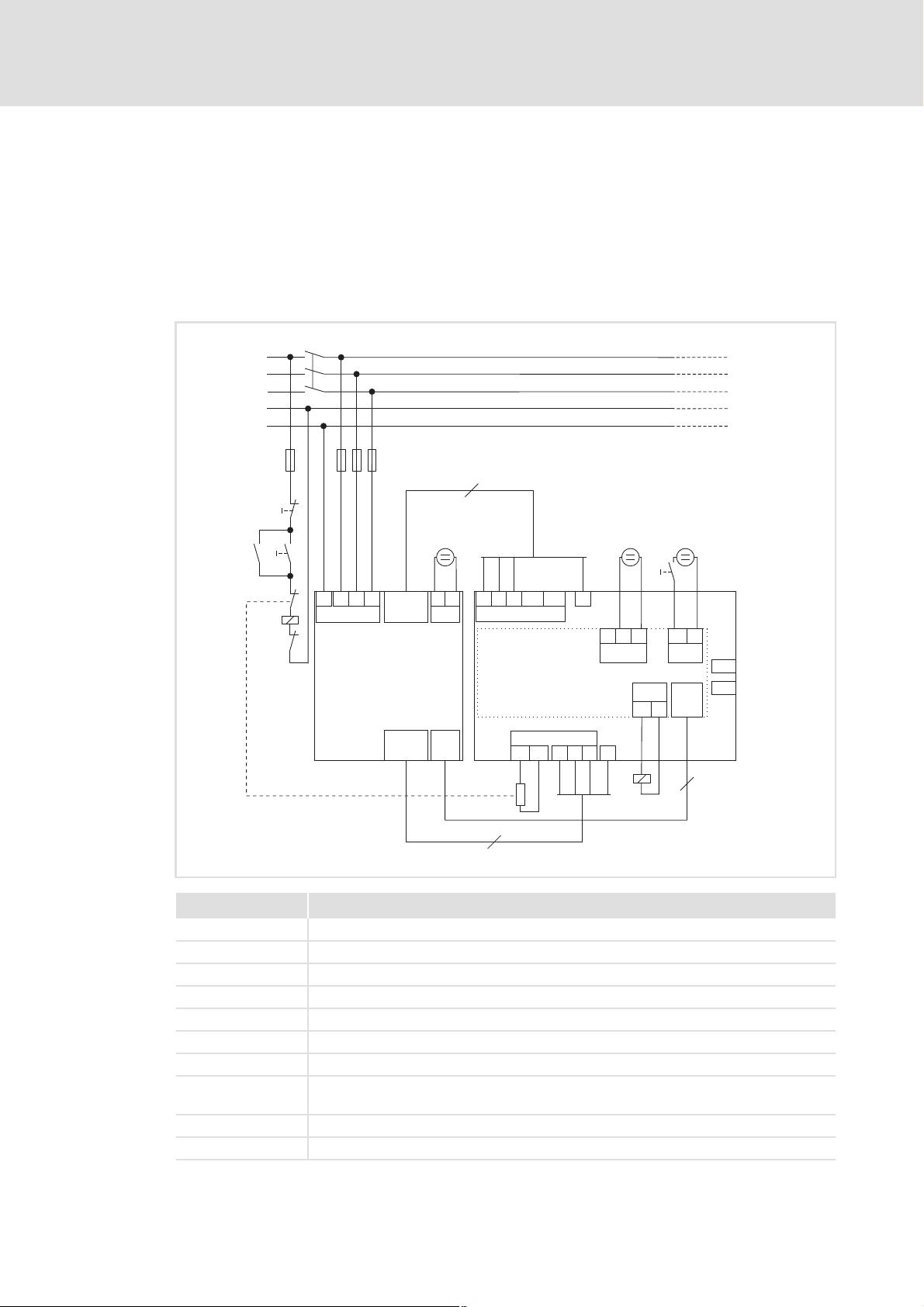
2.1.1 Example circuit
Commissioning
Short setup
94PSPVR01
Name Component
E94ARNE0xx4 Regenerative power supply module
E94AZPP0364 Installation backplane of regenerative power supply module
E94AZMR0... Mains filter
F1 ... F4 Fuses
RFR Controller enable (only for regenerative feedback)
K1 Mains contactor
RB Brake resistor
24-V voltage source for the control electronics
24-V voltage source for the digital inputs in accordance with IEC 61131-2
From version 02.00: Overtemperature disconnection (DO2 load: max. 50 mA)
EDS94ARNExxxx EN 2.3 - 06/2014 L 13
(safely separated power supply unit (SELV/PELV), in accordance with IEC 61131-2)
Page 14

9400 regenerative power supply module | Parameter setting
Commissioning
Short setup
2.1.2 Commissioning with the keypad
1. Switch on 24-V supply of the regenerative power supply module.
– With the first switch-on of the regenerative power supply module, the filter data are
automatically read out of the electronic filter nameplate (ENP) and temporarily
saved in the regenerative power supply module.
2. If the mains voltage is not 400/415 V, adapt the Lenze setting in C00173
– Note: A change of the setting in C00173
utilisation! In the chapter "Rated data" of the Hardware Manual, the device types
and their permissible device utilisation at different mains voltages and switching
frequencies are specified.
3. Carry out optional parameter setting:
– Parameterising the brake chopper/brake resistor
– Signal configuration
4. Save the parameter set (C00002
– By saving the parameter set, certain data such as the filter data are permanently
available in the regenerative power supply module and do not need to be read again
from the electronic filter nameplate at the next switch-on. This shortens the
initialisation time correspondingly.
5. Switch on mains voltage the DC bus is charged.
6. Deactivate controller inhibit via controller enable terminal (RFR) regenerative
feedback is enabled.
7. Controlling the regenerative power supply module via terminals
( 30)
= "11: Save start parameters").
also has an impact on the permissible device
( 22)
. ( 19)
accordingly.
14 L EDS94ARNExxxx EN 2.3 - 06/2014
Page 15
9400 regenerative power supply module | Parameter setting
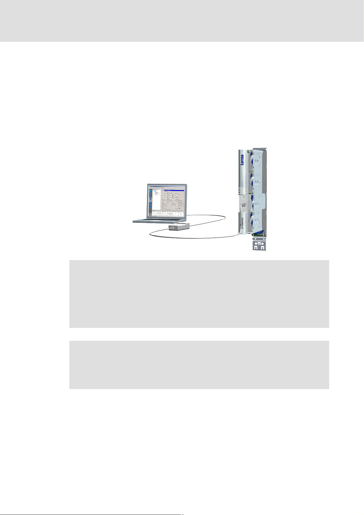
2.1.3 Commissioning with the Engineer
For commissioning with the Lenze PC software »Engineer« you need:
A PC with the following system requirements:
– Processor with at least 1.4 GHz
– At least 512 MB RAM and 650 MB of free hard disk space
– Operating system Microsoft® Windows® 2000 (service pack 2 or higher) or
Windows® XP
A connection to the regenerative power supply module, e. g. via the diagnostic adapter
offered by Lenze.
Commissioning
Short setup
Note!
Please observe the documentation for the diagnostic adapter!
For communication with the regenerative power supply module, at least the
control electronics of the regenerative power supply module must be supplied
with 24-V low voltage via the connector X2; detailed information on this can be
found in the Mounting Instructions for the regenerative power supply module.
Stop!
If you alter parameters in the »Engineer« while an online connection to the
regenerative power supply module is established, the changes are directly
accepted in the regenerative power supply module!
Tip!
An online connection can also be established via optional interfaces which are
provided by corresponding communication modules in the module receptacles
MXI1/MXI2 of the regenerative power supply module.
Detailed information about the different interfaces can be found in the
corresponding Communication Manuals.
EDS94ARNExxxx EN 2.3 - 06/2014 L 15
Page 16
9400 regenerative power supply module | Parameter setting
Commissioning
Short setup
How to carry out the commissioning with the »Engineer«:
1. Start the »Engineer«.
2. Select the procedure in the Start-up wizard.
• For instance, select the option "Select component from catalog".
3. Add the corresponding components from the catalog to the project:
• Regenerative power supply module
• Available device modules
• Regenerative power supply module application
Project view example in the »Engineer«:
4. Select the regenerative power supply module in the Project view.
5. Change to the Application parameters tab in the Workspace.
6. If the mains voltage is not 400/415 V, adapt the Lenze setting accordingly in the
Mains voltage list field.
Note: A change of the setting in C00173
device utilisation! In the chapter "Rated data" of the Hardware Manual, the device
types and their permissible device utilisation at different mains voltages and
switching frequencies are specified.
16 L EDS94ARNExxxx EN 2.3 - 06/2014
also has an impact on the permissible
Page 17
9400 regenerative power supply module | Parameter setting
Commissioning
Short setup
7. Carry out optional parameter setting:
• Parameterising the brake chopper/brake resistor
• Signal configuration
• Establish network/communication.
8. Switch on 24-V supply of the regenerative power supply module.
• With the first switch-on of the regenerative power supply module, the filter
data are automatically read out of the electronic filter nameplate (ENP) and
temporarily saved in the regenerative power supply module.
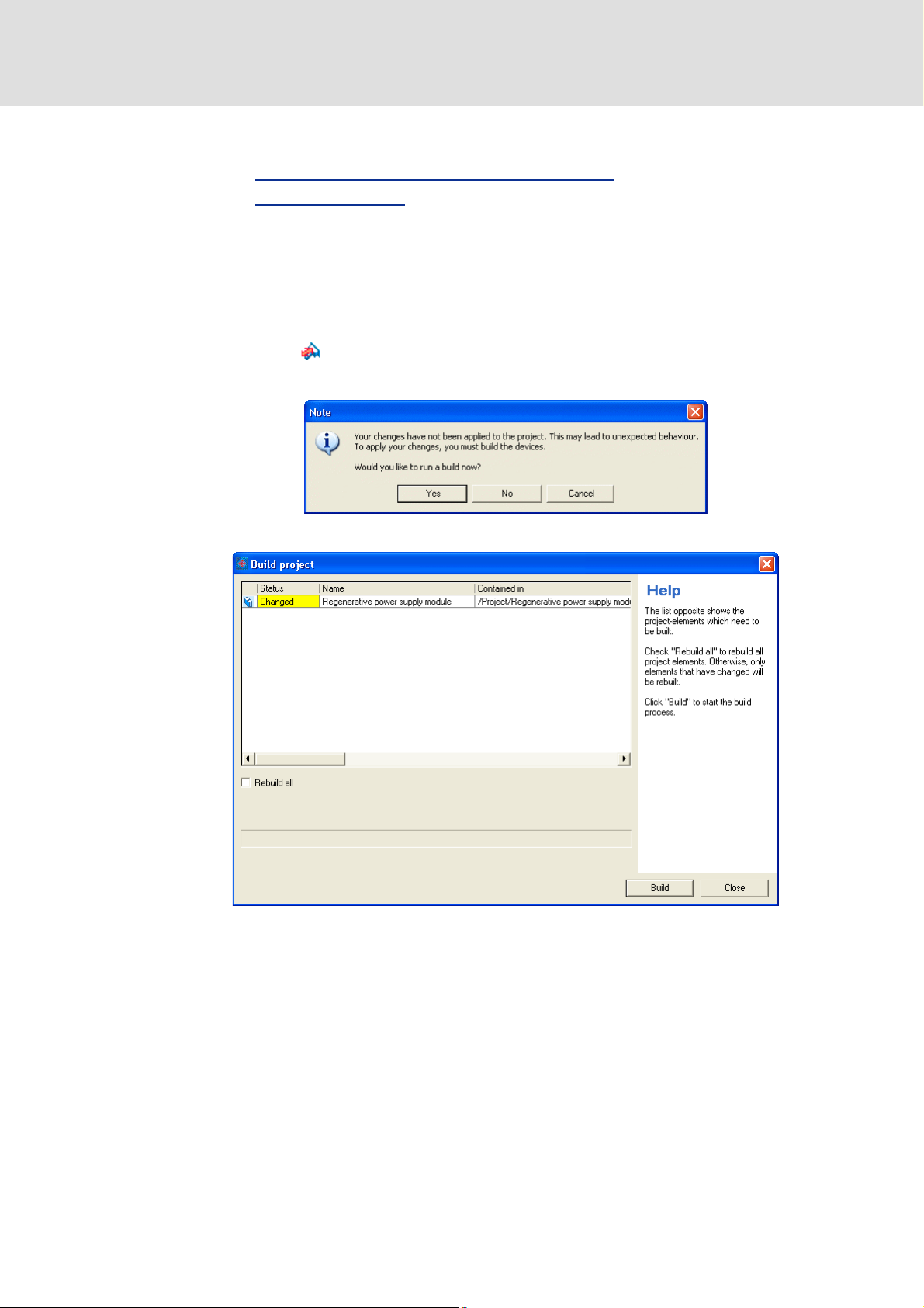
9. Click the icon.
10. Confirm the following note with Yes to accept the changes on the project:
( 30)
( 22)
The Build project dialog box is displayed:
11. Click Build to build the project.
• After the project has been built successfully, a corresponding note is displayed.
EDS94ARNExxxx EN 2.3 - 06/2014 L 17
Page 18
9400 regenerative power supply module | Parameter setting
Commissioning
Short setup
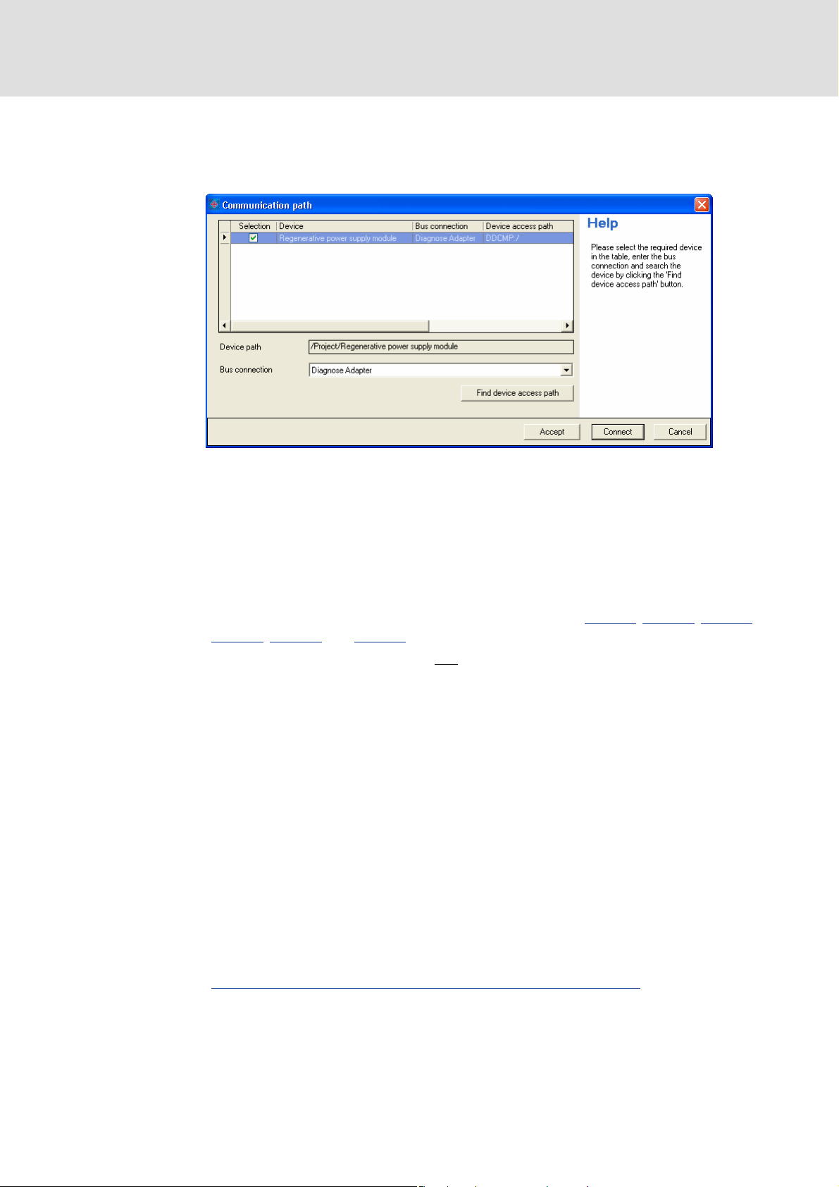
12. Confirm the note that the project has been built successfully with OK.
If no communication path has been configured for the regenerative power supply
module yet, the Communication path dialog box is displayed:
13. Set the bus connection (e. g. "Diagnostic adapter") to the regenerative power
supply module in the Communication path dialog box.
14. Click Connect to establish the online connection to the regenerative power supply
module.
• After the connection has been established successfully, the Transfer to device
dialog box is displayed.
Note: The following parameters are set automatically in the regenerative power
supply module via the electronic filter nameplate (ENP): C00070
C00076
• »Engineer« versions ≥ V2.9 do not
• If an older »Engineer« version is used, these parameters have to be saved prior
15. Click Start in the Transfer to device dialog box.
16. Confirm the query on whether the device is to be inhibited and the application is
to be stopped with Yes.
• Then the transmission is started.
17. After the transmission has been carried out successfully, confirm the query on
whether the application is to be started with Yes.
, C00084 and C00085.
overwrite these parameters during a
parameter download.
to a parameter download and then reset manually to the saved values.
, C00071, C00075,
18. Also confirm the query on whether the device is to be enabled with Yes.
19. Switch on mains voltage the DC bus is charged.
20. Deactivate controller inhibit via controller enable terminal (RFR) regenerative
feedback is enabled.
21. Controlling the regenerative power supply module via terminals
18 L EDS94ARNExxxx EN 2.3 - 06/2014
.
Page 19

9400 regenerative power supply module | Parameter setting
Note!
The regenerative power supply module still remains inhibited via the controller
enable terminal (RFR) if this terminal is set to LOW level.
Commissioning
Short setup
Please note that the regenerative power supply module will only be enabled if all
sources for controller inhibit are reset!
• The sources or trip elements that are active for controller inhibit are displayed
in a bit-coded manner in C00158
2.1.4 Controlling the regenerative power supply module via terminals
If the regenerative power supply module is enabled, the application can be controlled via
the digital inputs and/or MotionBus (if it is integrated in a network).
Terminal assignment of digital inputs
Terminal Assignment (Lenze setting)
X5 RFR Controller enable
DI1 Inhibit regenerative feedback
• Function also possible via bit 01 of control word 1.
DI2 Activate brake chopper
• Function also possible via bit 02 of control word 1.
DI3 Reset (acknowledge) error
• A pending error message can be reset (acknowledged) by a LOW-HIGH edge if the cause of
the error message has been eliminated.
• Function also possible via bit 07 of control word 1.
.
Tip!
Detailed information on device applications can be found in the chapter
"Regenerative power supply module application
". ( 21)
EDS94ARNExxxx EN 2.3 - 06/2014 L 19
Page 20

9400 regenerative power supply module | Parameter setting
Commissioning
Device replacement
2.2 Device replacement
Scenario: The regenerative power supply module in a running system has failed.
Note!
For the procedure described below we assume that the memory module and
possibly available extension modules in the regenerative power supply module
and the filter are not affected by the failure and all parameters have been stored
with mains failure protection.
Worksteps
Replacement of the regenerative power supply module:
1. Replace regenerative power supply module.
See Mounting Instructions for the regenerative power supply module!
2. Insert memory module of the regenerative power supply module that has failed into the replacement
device.
3. If further extension modules are plugged into the failed regenerative power supply module, they must
also be inserted into the replacement device.
Further steps are not required since all required data are stored on the memory module.
2.3 Filter replacement
Scenario: The filter in a running system has failed.
Note!
In the procedure described below we assume that the regenerative power
supply module is not affected by the failure.
Worksteps
Replacement of the filter:
1. Replace filter.
For a filter with an electronic nameplate (ENP):
2. Restart regenerative power supply module with connected filter to read out the filter data from the
3. Execute device command C00002
For a filter without an electronic nameplate (ENP):
See Mounting Instructions for the regenerative power supply module!
electronic nameplate.
• Restart the device either by switching the voltage supply off and on again, or via the device
command C00002
Note:
The filter is operated with the filter data from the memory module.
= "11000: Restart regenerative power supply module".
= "11: Save start parameters".
20 L EDS94ARNExxxx EN 2.3 - 06/2014
Page 21
9400 regenerative power supply module | Parameter setting
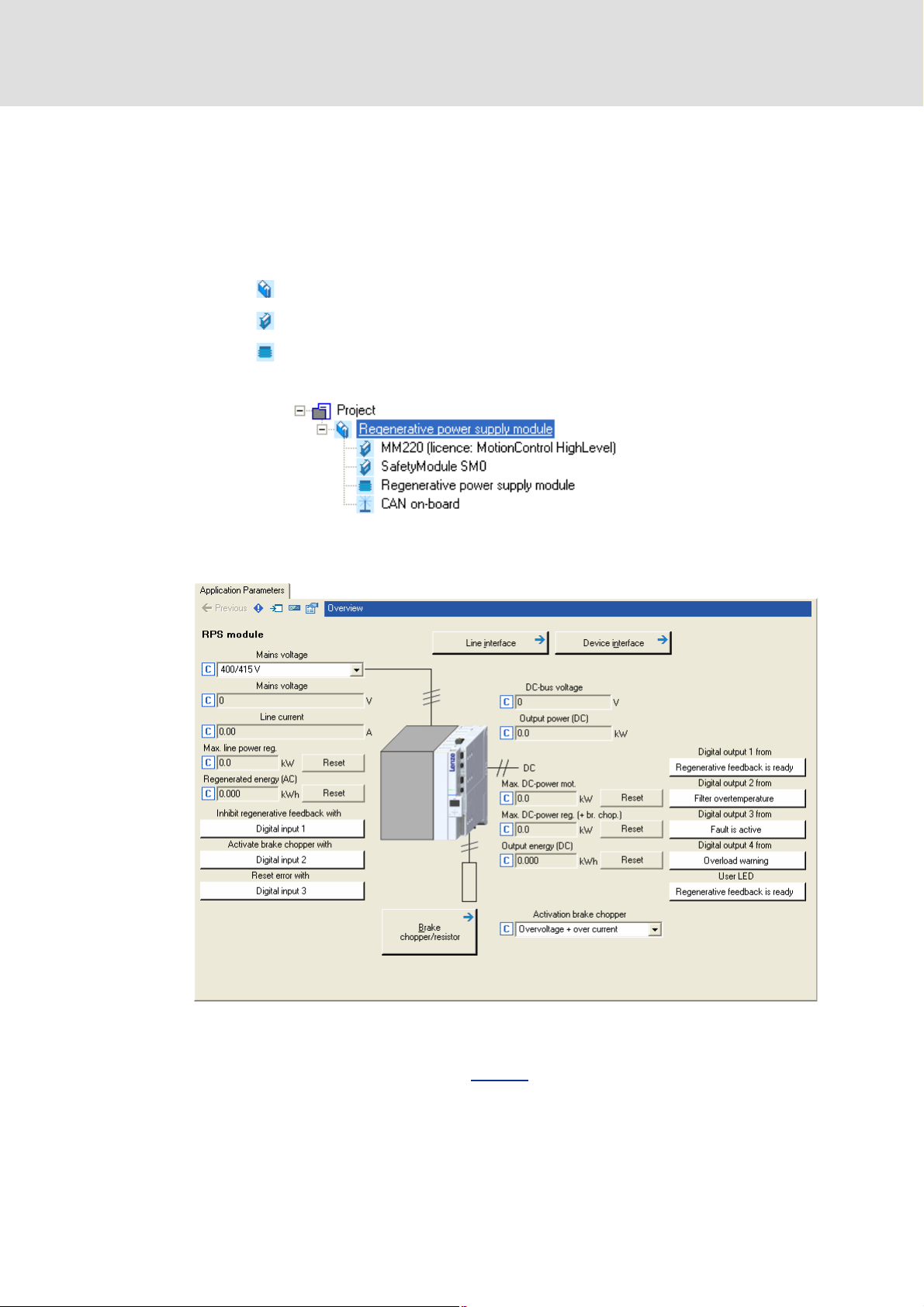
Regenerative power supply module application
3 Regenerative power supply module application
This chapter provides you with information on the "Regenerative power supply module"
application by which the regenerative power supply module can be controlled via digital
inputs and input ports. Status information is provided to other applications via digital
outputs and output ports.
How to get to the parameterisation dialog of the application:
1. Select the regenerative power supply module in the Project view of the »Engineer«.
2. Change to the Application parameters tab in the Workspace.
Parameterisation dialog in the »Engineer«
The white buttons show the assignment of the control inputs and status outputs of the
application.
– The assignment is defined by the "Regenerative power supply module" application
and can, if required, be reconfigured by clicking the corresponding button.
If you click the button marked with the icon, you get to the parameterisation dialog
for the brake chopper/brake resistor, which is one level beneath.
EDS94ARNExxxx EN 2.3 - 06/2014 L 21
Page 22

9400 regenerative power supply module | Parameter setting
Regenerative power supply module application
Parameterising the brake chopper/brake resistor
3.1 Parameterising the brake chopper/brake resistor
The regenerative power supply module is equipped with an integrated brake transistor.
The required brake resistor has to be connected externally (see mounting instructions/
hardware manual).
The rated values for the brake transistor are listed in the Hardware Manual, chapter
"Rated data".
Stop!
If the connected brake resistor has a lower resistance than the parameterised
brake resistor, the brake transistor may be damaged!
The brake resistor can be thermally overloaded. Carry out protective measures
suitable for the system, e.g.:
• Parameterisation of an error response in C00574
parameterised error message in the application or machine control. I2t
utilisation of brake resistor ( 27)
• External wiring using the temperature contact on the brake resistor (e.g.
interruption of the supply via mains contactor and activation of the
mechanical brakes).
and evaluation of the
22 L EDS94ARNExxxx EN 2.3 - 06/2014
Page 23
9400 regenerative power supply module | Parameter setting
Regenerative power supply module application
Parameterising the brake chopper/brake resistor
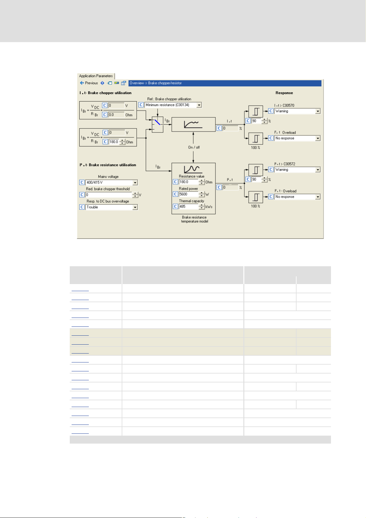
The brake chopper/brake resistor can be parameterised in the »Engineer» on the
Application parameters tab, dialog level Overview Brake chopper/resistor:
Short overview: Parameters for braking operation
Parameter Information Lenze setting
Value Unit
C00129 Brake resistor value 180.0 Ohm
C00130
C00131
C00132
C00133
C00134 Minimum brake resistance - Ohm
C00137 Brake transistor utilisation - %
C00138 Brake resistor utilisation - %
C00173
C00181
C00569
C00570
C00571
C00572
C00573
C00574
C00600
Highlighted in grey = display parameter
Rated power of brake resistor 5600 W
Therm. capacity brake resistor 485 kWs
Activation brake chopper At overvoltage and overcurrent
Ref: Brake chopper utilisation Minimum resistance (C00134)
Mains voltage 400/415 V
Red. brake chopper threshold 0 V
Resp. brake trans. ixt > C00570 Warning
Warning thres. brake transistor 90 %
Resp. brake resist. i2t > C00572 Warning
Warning thres. brake resistor 90 %
Resp. to overload brake trans. No response
Resp. to overtemp. brake resist. No response
Resp. to DC bus overvoltage Trouble
EDS94ARNExxxx EN 2.3 - 06/2014 L 23
Page 24

9400 regenerative power supply module | Parameter setting
Regenerative power supply module application
Parameterising the brake chopper/brake resistor
3.1.1 Setting the voltage threshold for braking operation
The voltage threshold for braking operation is set via C00173
(reduced brake chopper threshold). When the brake chopper threshold is exceeded in the
DC bus, the brake chopper is switched on.
Mains voltage selected in C00173 Effective brake chopper threshold
230 V 390 V - value in C00181
400/415 V 725 V - value in C00181
460/480 V 765 V - value in C00181
500 V 790 V - value in C00181
3.1.2 Setting the brake chopper mode
For software versions below V2.0, the following applies:
The regenerative power supply module only feeds back to the mains and activates the
brake chopper if the inverter-side current reaches the maximum device current. If the
current is below the maximum device current and the DC-bus voltage is below the brake
chopper threshold, the brake chopper is not activated.
From software version V2.0 onwards, the following applies:
C00132
can be used to set the conditions for brake chopper activation:
(mains voltage) and C00181
(0 ... 100 V)
(0 ... 100 V)
(0 ... 100 V)
(0 ... 100 V)
Only at overvoltage:
The brake chopper is only activated if the DC-bus voltage has reached the brake
chopper threshold. This setting corresponds to the behaviour of the 9400 controller.
At overvoltage and overcurrent (Lenze setting):
This setting corresponds to the behaviour of regenerative power supply modules with
software versions below V2.0.
At overvoltage and overcurrent and overload:
With this setting, the brake chopper is used for energy consumption if a device
utilisation of 90 % is reached during feedback operation.
– The "normal" voltage thresholds for braking operation still apply. Setting the
voltage threshold for braking operation ( 24)
– To protect the brake chopper against damage, monitoring of the Ixt utilisation is still
active. Ixt utilisation of brake transistor
( 26)
24 L EDS94ARNExxxx EN 2.3 - 06/2014
Page 25

9400 regenerative power supply module | Parameter setting
3.1.3 Monitoring
3.1.3.1 Overcurrent protection
The brake chopper hardware is monitored for overcurrent (short circuit or earth fault).
Note!
Monitoring for overcurrent can only be activated if a real brake current flows. A
test in idle state (without a brake resistor connected) is not possible.
If the monitoring function responds:
– The brake chopper is switched off immediately.
– The "Fault" response that is set fixedly is activated.
– The "Brake transistor: overcurrent" error message is entered in the logbook of the
regenerative power supply module.
Regenerative power supply module application
Parameterising the brake chopper/brake resistor
Note!
The error can only be acknowledged after 2 seconds at the earliest to resume the
braking operation.
Tip!
In addition to the overcurrent protection, the regenerative power supply module is
provided with two more monitoring modes for braking operation, which are active
even if no brake resistor is connected (testing mode for checking the parameter
setting):
Ixt utilisation of brake transistor
I2t utilisation of brake resistor
( 26)
( 27)
EDS94ARNExxxx EN 2.3 - 06/2014 L 25
Page 26
9400 regenerative power supply module | Parameter setting
Ixt
C00137
1
0
C00134
C00129
C00133
T=0
Off
T=1
On
100 %
C00570
C00569
C00573
Logbook entry "Brake chopper: Ixt > C00570"
Logbook entry " "Brake chopper: Ixt overload
U
DC_act
U
DC_act
I=
Br
I=
Br
I
Br
= f(duty cycle, R )
Br
Regenerative power supply module application
Parameterising the brake chopper/brake resistor
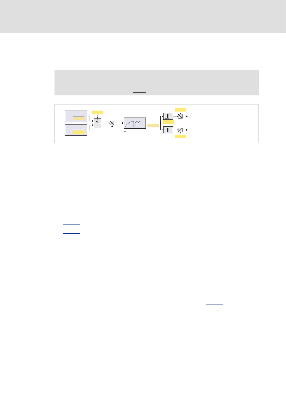
3.1.3.2 Ixt utilisation of brake transistor
The regenerative power supply module monitors the Ixt utilisation of the internal brake
transistor.
Note!
The braking operation will never be switched off by this monitoring function.
[3-1] Signal flow of Ixt utilisation - brake chopper
The monitoring function is based on a mathematical model which calculates the
braking current from the current DC-bus voltage and the brake resistance
parameterised.
– Hence, the monitoring function can respond even if no brake resistor is connected
and can therefore also be used for a testing mode to check the parameterisation.
The calculation considers the thermal utilisation of the brake transistor by a
correspondingly adapted time constant.
Use C00133
setting in C00173
C00129
C00137
to select whether the minimum brake resistance depending on the mains
(display in C00134), or the brake resistance value parameterised in
is to be used as a reference for calculating the utilisation.
displays the calculated utilisation of the brake transistor in [%].
– A 100 % utilisation corresponds to the continuous braking power which is provided
by the brake chopper at a DC-bus voltage of 790 V (or 390 V at a mains voltage of
230 V).
– The maximum braking power (assuming that the utilisation starts at 0 %) can be
provided for a period depending on the device.
– The calculated utilisation is also provided as the oscilloscope signal
Common.dnIxtBrakeChopper to check the braking operation while the system is
running
30
(scaling: 2
≡ 100 %).
If the utilisation exceeds the advance warning threshold set in C00570
, the message
"Brake chopper: Ixt > C00570" is entered into the logbook and the response set in
C00569
26 L EDS94ARNExxxx EN 2.3 - 06/2014
(default setting: "Warning") is activated.
Page 27
9400 regenerative power supply module | Parameter setting
I2t
C00138
C00129
T=0
Off
T=1
On
100 %
C00572
C00571
C00574
C00129
C00130
C00131
Logbook entry " "Brake resistor: I2t > C00572
Logbook entry " "Brake resistor: I2t overload
U
DC_act
Temperature model
I=
Br
I
Br
When the utilisation reaches the limit value (100 %):
– The activation of the brake chopper is reset to the permanently permissible pulse-
no-pulse ratio (taking into account the parameterised brake resistance). (The brake
chopper is activated with 4 kHz, which means that it can be switched on/off at
minimum intervals of 250 μs.)
– The response set in C00573
corresponding effects on the state machine and the inverter.
Note!
If the DC-bus voltage exceeds the overvoltage threshold due to a too high
braking energy, the monitoring function for overvoltage in the DC bus responds.
DC-bus overvoltage
3.1.3.3 I2t utilisation of brake resistor
Regenerative power supply module application
Parameterising the brake chopper/brake resistor
(default setting: "No response") is activated with the
( 29)
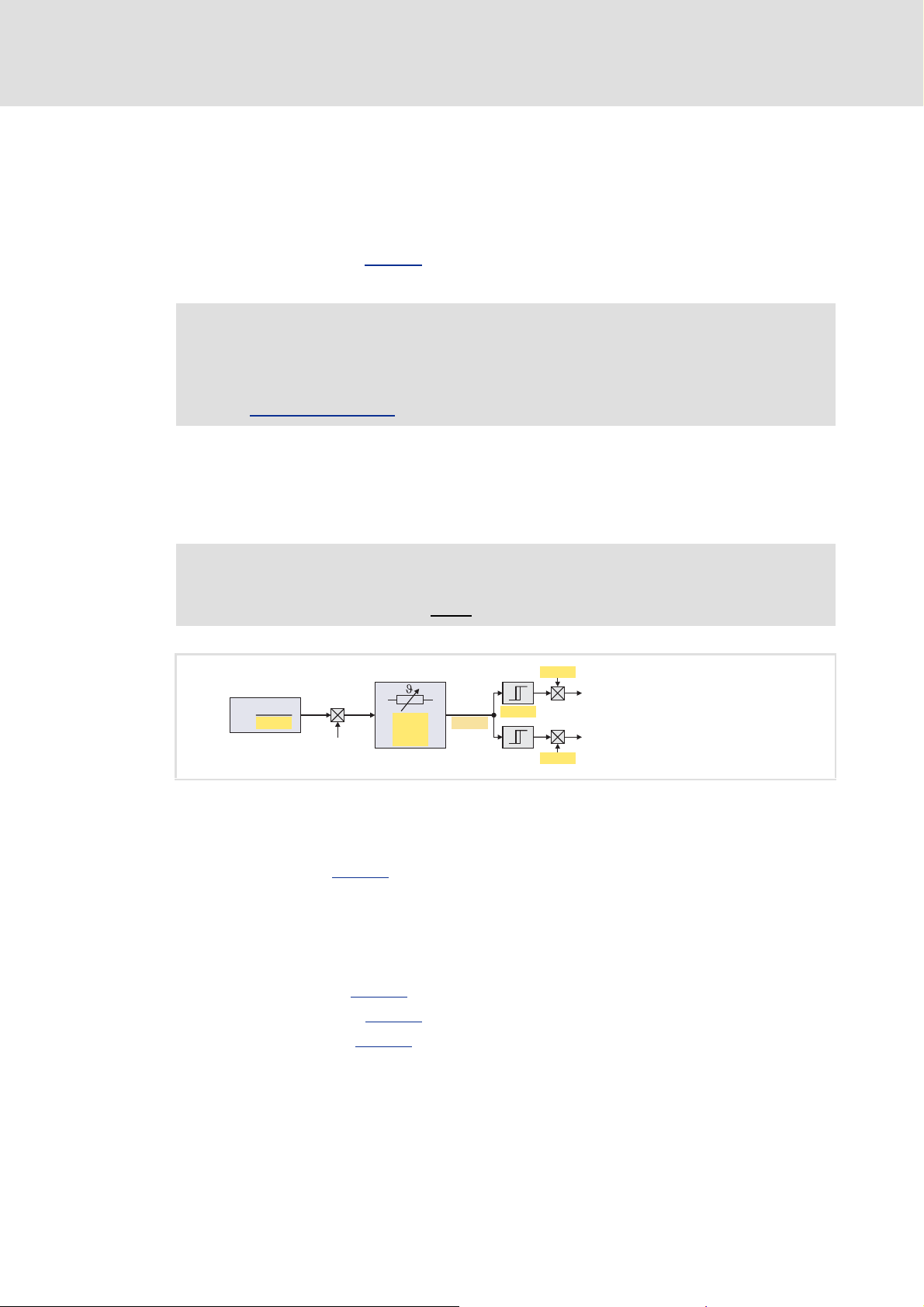
The regenerative power supply module is provided with a monitoring function for the I
utilisation of the brake resistor which is proportional to the converted braking power.
Note!
The braking operation will never be switched off by this monitoring function.
[3-2] Signal flow - I2t utilisation - brake resistor
The monitoring function is based on a mathematical model which calculates the
braking current from the current DC-bus voltage and the brake resistance
parameterised in C00129
– Hence, the monitoring function can respond even if no brake resistor is connected
and can therefore also be used for a testing mode to check the parameterisation.
.
2
t-
The calculation considers the thermal utilisation of the brake resistor based on the
following parameters:
– Resistance value (C00129
– Continuous power (C00130
– Thermal capacity (C00131
EDS94ARNExxxx EN 2.3 - 06/2014 L 27
)
)
)
Page 28

9400 regenerative power supply module | Parameter setting
Regenerative power supply module application
Parameterising the brake chopper/brake resistor
C00138 displays the calculated utilisation of the brake resistor in [%].
– A 100 % utilisation corresponds to the continuous power of the brake resistor
resulting at the maximum permissible temperature limit of the brake resistor.
– The calculated utilisation is also provided as the oscilloscope signal
Common.dnI2tBrakeResistor to check the braking operation while the system is
running
(scaling: 2
30
≡ 100 %).
If the utilisation exceeds the advance warning threshold set in C00572
"Brake resistor: I2t > C00572" is entered into the logbook and the response set in
C00571
When the utilisation reaches the limit value (100 %):
– The response set in C00574
– The activation of the brake chopper is reset to the permanently permissible pulse-
(default setting: "Warning") is activated.
(default setting: "No response") is activated with the
corresponding effects on the state machine and the inverter.
no-pulse ratio (taking into account the parameterised brake resistance). (The brake
chopper is activated with 4 kHz, which means that it can be switched on/off at
minimum intervals of 250 μs.)
, the message
Stop!
The brake resistor can be thermally overloaded. Carry out protective measures
suitable for the system, e.g.:
• Parameterisation of an error response in C00574
parameterised error message in the application or machine control.
• External wiring using the temperature contact on the brake resistor (e.g.
interruption of the supply via mains contactor and activation of the
mechanical brakes).
and evaluation of the
Note!
If the system is dimensioned correctly, this monitoring function should not
respond. If individual rated data of the connected brake resistor are not known,
they must be determined "empirically".
From software version V2.0 onwards, C00571
the error response "Brake chopper is inhibited".
• If this error response occurs, the brake chopper is inhibited without providing
feedback to the device control. Instead, feedback is provided via the
LI_bChopperOffByTrouble output of the LS_LineInterface
• If the corresponding trigger threshold is fallen below by 5 %, the pulse inhibit
of the brake chopper is deactivated again and the status signal
LI_bChopperOffByTrouble is reset to FALSE.
and C00574 additionally provide
system block.
28 L EDS94ARNExxxx EN 2.3 - 06/2014
Page 29

9400 regenerative power supply module | Parameter setting
3.1.3.4 DC-bus overvoltage
If the braking energy is too high and the DC-bus voltage therefore exceeds the overvoltage
threshold which results from the mains setting in C00173
error message is output and the response set in C00600
"Trouble").
Note!
For hoist applications the "Fault" response should be selected in C00600 (in
combination with an emergency stop via mechanical brakes).
Regenerative power supply module application
Parameterising the brake chopper/brake resistor
, the "Overvoltage in the DC bus"
is activated (default setting:
EDS94ARNExxxx EN 2.3 - 06/2014 L 29
Page 30

9400 regenerative power supply module | Parameter setting
Regenerative power supply module application
Signal configuration
3.2 Signal configuration
3.2.1 Device and line interface
If required, the default signal configuration of the control and setpoint inputs of the device
and line interface can be easily reconfigured by parameterising the multiplexer
parameters assigned.
Device interface
Signal (Lenze setting) Control input Signal configuration
DIGIN 1 Set controller inhibit
(inhibit regenerative feedback)
Control word 1 bit 01 Set controller inhibit
(inhibit regenerative feedback)
DIGIN 3 Reset error 1 C03130/3
Control word 1 bit 07 Reset error 2 C03130/4
C03130/1
C03130/2
Line interface
Signal (Lenze setting) Control input Signal configuration
DIGIN 2 Activate brake chopper C03190/1
Control word 1 bit 02 Activate brake chopper C03190/2
30 L EDS94ARNExxxx EN 2.3 - 06/2014
Page 31

3.2.2 Output ports
If required, the default signal configuration of the output ports can be easily reconfigured
by parameterising the multiplexer parameters assigned.
Output port "LPortAxisOut1"
The output port LPortAxisOut1 is intended for the connection to a following axis.
Signal (Lenze setting) Output port Signal configuration
Axis status word
• Application-specific signals can be added.
Setpoints for horizontal communication
9400 regenerative power supply module | Parameter setting
Regenerative power supply module application
Signal configuration
FALSE Axis status word bit 00 C03120/1
FALSE Axis status word bit 01 C03120/2
FALSE Axis status word bit 02 C03120/3
FALSE Axis status word bit 03 C03120/4
FALSE Axis status word bit 04 C03120/5
FALSE Axis status word bit 05 C03120/6
FALSE Axis status word bit 06 C03120/7
FALSE Axis status word bit 07 C03120/8
FALSE Axis status word bit 08 C03120/9
FALSE Axis status word bit 09 C03120/10
FALSE Axis status word bit 10 C03120/11
FALSE Axis status word bit 11 C03120/12
FALSE Axis status word bit 12 C03120/13
FALSE Axis status word bit 13 C03120/14
FALSE Axis status word bit 14 C03120/15
FALSE Axis status word bit 15 C03120/16
0 % Axis port out 1 (16 bits) C03124/1
0 % Axis port out 2 (32 bits) C03124/2
EDS94ARNExxxx EN 2.3 - 06/2014 L 31
Page 32

9400 regenerative power supply module | Parameter setting
Regenerative power supply module application
Signal configuration
Output port "LPortStatus1"
The output port LPortStatus1 is intended for the connection to a higher-level control
system.
Signal (Lenze setting) Output port Signal configuration
Status word 1
FALSE Status word 1 bit 00 C03121/1
FALSE Status word 1 bit 01 C03121/2
FALSE Status word 1 bit 02 C03121/3
FALSE Status word 1 bit 03 C03121/4
FALSE Status word 1 bit 04 C03121/5
FALSE Status word 1 bit 05 C03121/6
FALSE Status word 1 bit 06 C03121/7
FALSE Status word 1 bit 07 C03121/8
FALSE Status word 1 bit 08 C03121/9
FALSE Status word 1 bit 09 C03121/10
FALSE Status word 1 bit 10 C03121/11
FALSE Status word 1 bit 11 C03121/12
FALSE Status word 1 bit 12 C03121/13
FALSE Status word 1 bit 13 C03121/14
FALSE Status word 1 bit 14 C03121/15
FALSE Status word 1 bit 15 C03121/16
Output port "LPortStatus2"
The output port LPortStatus2 is intended for the connection to a higher-level control
system.
Signal (Lenze setting) Output port Signal configuration
Status word 2
FALSE Status word 2 bit 00 C03122/1
FALSE Status word 2 bit 01 C03122/2
FALSE Status word 2 bit 02 C03122/3
FALSE Status word 2 bit 03 C03122/4
FALSE Status word 2 bit 04 C03122/5
FALSE Status word 2 bit 05 C03122/6
FALSE Status word 2 bit 06 C03122/7
FALSE Status word 2 bit 07 C03122/8
FALSE Status word 2 bit 08 C03122/9
FALSE Status word 2 bit 09 C03122/10
FALSE Status word 2 bit 10 C03122/11
FALSE Status word 2 bit 11 C03122/12
FALSE Status word 2 bit 12 C03122/13
FALSE Status word 2 bit 13 C03122/14
FALSE Status word 2 bit 14 C03122/15
FALSE Status word 2 bit 15 C03122/16
32 L EDS94ARNExxxx EN 2.3 - 06/2014
Page 33

9400 regenerative power supply module | Parameter setting
Regenerative power supply module application
Signal configuration
Output port "LPortStatus2"
The output port LPortStatus2 is intended for the connection to a higher-level control
system.
Signal (Lenze setting) Output port Signal configuration
Status word 2
FALSE Status word 2 bit 00 C03122/1
FALSE Status word 2 bit 01 C03122/2
FALSE Status word 2 bit 02 C03122/3
FALSE Status word 2 bit 03 C03122/4
FALSE Status word 2 bit 04 C03122/5
FALSE Status word 2 bit 05 C03122/6
FALSE Status word 2 bit 06 C03122/7
FALSE Status word 2 bit 07 C03122/8
FALSE Status word 2 bit 08 C03122/9
FALSE Status word 2 bit 09 C03122/10
FALSE Status word 2 bit 10 C03122/11
FALSE Status word 2 bit 11 C03122/12
FALSE Status word 2 bit 12 C03122/13
FALSE Status word 2 bit 13 C03122/14
FALSE Status word 2 bit 14 C03122/15
FALSE Status word 2 bit 15 C03122/16
EDS94ARNExxxx EN 2.3 - 06/2014 L 33
Page 34

9400 regenerative power supply module | Parameter setting
Regenerative power supply module application
Assignment of the I/O terminals
3.3 Assignment of the I/O terminals
In the following tables the Lenze assignment of the I/O terminals for the "Regenerative
power supply module" application is listed.
If required, the default signal configuration can be easily reconfigured via the
parameterisation dialog on the Application parameters tab, or via parameterisation of
the multiplexer parameters assigned.
Digital inputs
Terminal Assignment (Lenze setting)
X5 RFR Controller enable
DI1 Inhibit regenerative feedback
• Function also possible via bit 01 of control word 1.
DI2 Activate brake chopper
• Function also possible via bit 02 of control word 1.
DI3 Reset (acknowledge) error
• A pending error message can be reset (acknowledged) by a LOW-HIGH edge if the cause of
the error message has been eliminated.
• Function also possible via bit 07 of control word 1.
DI4 -
DI5 -
DI6 -
DI7 -
DI8 -
Digital outputs
Terminal Signal (Lenze setting) Signal configuration
X4 DO1 "Ready for regenerative feedback" state
• Mains voltage is applied.
• Charging of DC bus is completed.
• There is no short circuit or earth fault.
• There is no device overload, i.e. the device utilisation (C00064
below the warning threshold set in C00123
DO2 "Filter overtemperature" state C03100/2
DO3 "Fault active - acknowledgement required" state
• A monitoring function with the "Fault" response has been triggered
and the regenerative power supply module is in the "Fault active"
device state.
DO4 "Warning active" state
• A filter overload or device overload warning has occurred or another
monitoring function with the "Warning" error response has been
triggered and the regenerative power supply module is in the
"Warning active" device state.
.
) is
C03100/1
C03100/3
C03100/4
34 L EDS94ARNExxxx EN 2.3 - 06/2014
Page 35

9400 regenerative power supply module | Parameter setting
Note!
"Ready for regenerative feedback" status message via digital output DO1:
• If one of the conditions listed in the table for digital output DO1 is not met
anymore, the digital output DO1 is reset to LOW level.
Conditions for returning to the "ready for regenerative feedback" state:
• If a mains failure has been detected, the mains voltage has to be applied for
at least two complete periods after mains recovery, before the digital output
DO1 is reset to HIGH level.
• If a short circuit or earth fault has occurred, the device is ready for operation
again after approx. 2 s, i.e. after this time the digital output DO1 is
automatically reset to HIGH level.
• The device utilisation evaluation has a hysteresis of 5 %. This means that the
device utilisation (C00064
output DO1 is reset to HIGH level.
Regenerative power supply module application
Assignment of the I/O terminals
) must drop to < (C00123 - 5 %) before the digital
Display elements
User LED Signal (Lenze setting) Signal configuration
"Ready for regenerative feedback" state
• See description for digital output DO1.
C03100/5
State bus
Terminal Signal (Lenze setting) Signal configuration
X2 SB FALSE C03100/6
Analog outputs
Terminal Signal (Lenze setting) Signal configuration
X3 AO1 0 % C03110/1
AO2 0 % C03110/2
Related topics:
Analog outputs
( 92)
Digital inputs
Digital outputs
"State bus" monitoring function
LED status displays for the device state
EDS94ARNExxxx EN 2.3 - 06/2014 L 35
( 94)
( 95)
( 96)
( 188)
Page 36

9400 regenerative power supply module | Parameter setting
Device interface
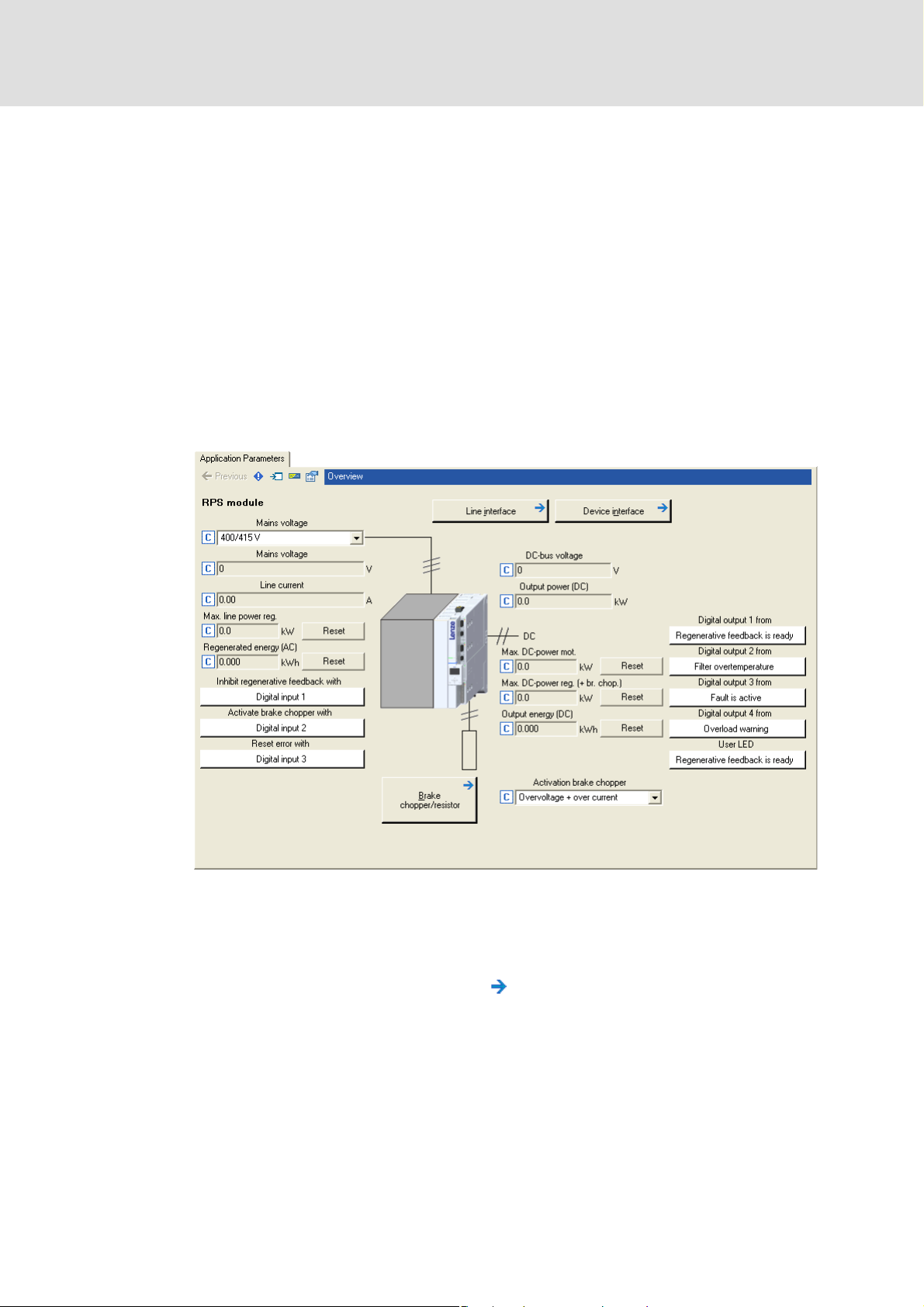
4 Device interface
This chapter will provide you with information on the device interface via which you can
query the states of the regenerative power supply module and set it to specific states.
How to get to the parameterisation dialog of the device interface:
1. Select the regenerative power supply module in the Project view of the »Engineer«.
2. Change to the Application parameters tab in the Workspace.
3. Click the Device interface button in the Overview dialog box.
Parameterisation dialog in the »Engineer«
The white buttons display the configuration of the device interface inputs.
LS_DriveInterface - device interface
– The assignment is defined by the technology application selected and can, if
required, be reconfigured by clicking the corresponding button.
If you click a button marked with the icon, you get one level deeper in the
corresponding parameterisation dialog.
( 259)
36 L EDS94ARNExxxx EN 2.3 - 06/2014
Page 37

9400 regenerative power supply module | Parameter setting
4.1 Device commands
The following subchapters describe the device commands of the regenerative power
supply module, which are available in C00002
or via the »Engineer« when an online connection has been established.
Note!
Before switching off the supply voltage after a device command has been
executed, check via the status display in C00003
been executed successfully!
Device interface
Device commands
and which can be executed using the keypad
that the device command has
The meaning of the status display in C00003
subchapter for the corresponding device command.
Activating frequently required device commands via the toolbar
Frequently required device commands can be executed very easily directly via the Toolbar
of the »Engineer« when an online connection has been established.
Icon Function
Enable controller
Inhibit controller
Start application
Stop application and Inhibit controller
can be obtained from the
Note!
Device commands that can be executed via the Toolbar of the »Engineer« always
affect the element that is currently selected in the Project View and all
subelements!
• If, for example, a system module is selected in the Project view instead of the
regenerative power supply module, the corresponding device command will
be activated in all lower-level regenerative power supply modules &
controllers that are currently connected online with the »Engineer«.
Before the corresponding action is executed, a confirmation prompt is displayed
to ask you if this action should really be carried out.
EDS94ARNExxxx EN 2.3 - 06/2014 L 37
Page 38

9400 regenerative power supply module | Parameter setting
Device interface
Device commands
Activating device commands via the "Device commands" dialog box
All device commands of the regenerative power supply module are available in the
»Engineer« in the Device Commands dialog box:
The Device Commands dialog box can be opened by clicking on the setting of C00002
on the All Parameters tab.
Note!
If you click on a device command in the list field of the Device Commands dialog
box, the corresponding device command is executed immediately!
During and after the execution of the device command, the processing status is
displayed in the Device Commands dialog box:
38 L EDS94ARNExxxx EN 2.3 - 06/2014
Page 39

9400 regenerative power supply module | Parameter setting
Application 3
PS
Application 2
PS
Memory module MM
PS
9400
PS
RAM
Firmware Application 1Application
PS
4.1.1 Load Lenze setting
Device interface
Device commands
The C00002
= "0: Load Lenze setting" device command can be used to reset the parameters
of the active application to the Lenze setting which is stored in the firmware of the
regenerative power supply module:
[4-1] "Load Lenze setting" function
Only possible when the controller is inhibited and the application has been stopped.
All parameter changes made since the last saving of the parameter set will get lost!
This device command only has an impact on the settings of the operating system,
application, and module parameters, the active application remains unchanged.
Possible status displays for this device command
Status (C00003) Meaning
34050 Device command in process
0 Device command executed successfully
1 General fault
39424 CAN fault
... ...
39679 CAN fault
Related device commands
Load start parameters
Save start parameters
( 40)
( 44)
EDS94ARNExxxx EN 2.3 - 06/2014 L 39
Page 40

9400 regenerative power supply module | Parameter setting
PS
9400
RAM
Firmware Application 1*
PS
Application 3
PS
Application 2
PS
Memory module MM
PS
Application 1*
Device interface
Device commands
4.1.2 Load start parameters
The C00002
= "1: Load start parameters" device command can be used to reload the start
parameters of the active application from the memory module into the regenerative
power supply module:
* In this example application 1 is the active application
[4-2] "Load start parameters" function
Only possible when the controller is inhibited and the application has been stopped.
All parameter changes made since the last saving of the parameter set will get lost!
This device command only has an impact on the settings of the operating system,
application, and module parameters, the active application remains unchanged.
Possible status displays for this device command
Status (C00003) Meaning
99586 Device command in process
65536 Device command executed successfully
65537 General fault
99371 Fault while reading the parameter set partition
99374 No memory module available
104960 CAN fault
... ...
105215 CAN fault
Related device commands
Save start parameters
Load Lenze setting
( 44)
( 39)
40 L EDS94ARNExxxx EN 2.3 - 06/2014
Page 41

9400 regenerative power supply module | Parameter setting
4.1.3 Load route data from the ENP
If the Lenze filter connected to the regenerative power supply module is provided with an
electronic nameplate (ENP), at the first switch-on of the regenerative power supply module
all filter data are automatically read out from the electronic nameplate of the filter and
temporarily saved in the regenerative power supply module.
Device interface
Device commands
The C00002
= "2: ENP: Load route data" device command can be used to reload the filter
data from the electronic nameplate (ENP) of the filter.
Only possible when the controller is inhibited and the application has been stopped.
For a permanent availability of the filter data, the parameter set must then be
saved.Save start parameters
( 44)
Possible status displays for this device command
Status (C00003) Meaning
165122 Device command in process
131072 Device command executed successfully
131073 General fault
EDS94ARNExxxx EN 2.3 - 06/2014 L 41
Page 42

9400 regenerative power supply module | Parameter setting
PS
9400
RAM
Firmware Application
PS
Application 3
Memory module MM
Application 1
Application 2*
PS
Device interface
Device commands
4.1.4 Activate application
If several applications are available on the memory module, the C00002
="5: Activate
application" device command can be used to activate the application with the number set
in C00005
* In this example the application selection "2" is set in C00005
[4-3] "Activate application" function
.
Only possible when the controller is inhibited and the application has been stopped.
The auto-start setting selected in C02104
determines whether the application is
started at the same time.
After mains switching, the default application is reloaded into the regenerative power
supply module.
If after mains switching another application than the one preset by Lenze is to be
loaded, this application must be activated first and then the selected application must
be saved with the device command "Save selected application
The number of the currently active application is displayed in C00007
" ( 43)
.
Note!
When the application is activated, the corresponding start parameter set is
loaded automatically and parameter settings executed before will get lost
unless the parameter set has been saved before!
Possible status displays for this device command
Status (C00003) Meaning
361730 Device command in process
327680 Device command executed successfully
327681 General fault
Related device commands
Save selected application
Start application
( 48) / Stop application ( 49)
( 43)
42 L EDS94ARNExxxx EN 2.3 - 06/2014
Page 43

9400 regenerative power supply module | Parameter setting
PS
9400
RAM
Firmware Application 2*
PS
Application 3
Memory module MM
Application 1
Application 2*
PS
4.1.5 Save selected application
After mains switching, the regenerative power supply module always loads the default
start application from the memory module, even if a different application has been active
before.
Device interface
Device commands
The device command C00002
= "7: Save selected application" can be used to define the
active application as start application.
* In this example the active application 2 is defined as start application
[4-4] "Save selected application" function
When this device command is executed, the parameter set is also saved automatically.
The number of the currently active application is displayed in C00007
Possible status displays for this device command
Status (C00003) Meaning
492802 Device command in process
458752 Device command executed successfully
.
458753 General fault
Related device commands
Activate application
Start application
Stop application
( 42)
( 48)
( 49)
EDS94ARNExxxx EN 2.3 - 06/2014 L 43
Page 44

9400 regenerative power supply module | Parameter setting
PS
9400
RAM
Firmware Application 1*
PS
Application 3
PS
Application 2
PS
Memory module MM
PS
Application 1*
Device interface
Device commands
4.1.6 Save start parameters
Parameter changes in the regenerative power supply module carried out via the
»Engineer« or keypad will get lost after mains switching of the regenerative power supply
module, or after loading another application, unless the settings have been explicitly
saved.
The C00002
parameter settings of the active application with mains failure protection in the memory
module of the regenerative power supply module.
* In this example application 1 is the active application
[4-5] "Save start parameters" function
= "11: Save start parameters" device command can be used to save the current
Tip!
The left function key of the keypad can be used to execute this device command if
the function is currently assigned to this key.
Note!
The storing process can take a few seconds. Before switching off the supply
voltage after this device command has been executed, check via the status
display in C00003
that the device command has been executed successfully!
44 L EDS94ARNExxxx EN 2.3 - 06/2014
Page 45

9400 regenerative power supply module | Parameter setting
Possible status displays for this device command
Status (C00003) Meaning
754946 Device command in process
720896 Device command executed successfully
720897 General fault
754718 Fault while writing to a file
754734 No memory module available
761857 Access to file has been denied since the file is already accessed from another position.
761861 I/O fault during accessing the file system
761868 RAM memory is full
761869 Access authorisation denied
761884 No free memory on the memory module
Device interface
Device commands
Related device commands
Load start parameters
( 40)
EDS94ARNExxxx EN 2.3 - 06/2014 L 45
Page 46

9400 regenerative power supply module | Parameter setting
Device interface
Device commands
4.1.7 Delete logbook
The C00002
logbook.
= "20: Delete logbook" device command serves to delete all entries in the
Tip!
To display the logbook in the »Engineer«, click the Logbook button on the
Diagnostics tab.
You can also delete all entries in the logbook by clicking the Delete button in the
Logbook dialog box.
Further information on the logbook can be found in the chapter "Diagnostics &
fault analysis". ( 187)
Possible status displays for this device command
Status (C00003) Meaning
1344770 Device command in process
1310720 Device command executed successfully
1310721 General fault
Related device commands
Archive log file
( 47)
46 L EDS94ARNExxxx EN 2.3 - 06/2014
Page 47

9400 regenerative power supply module | Parameter setting
4.1.8 Archive log file
Device interface
Device commands
The C00002
= "21: Archive log file" device command serves to archive the logbook entries.
Tip!
To display the logbook in the »Engineer«, click the Logbook button on the
Diagnostics tab.
You can also export the logbook entries to a file (*.log) by clicking the Export button
in the Logbook dialog box.
Further information on the logbook can be found in the chapter "Diagnostics &
fault analysis". ( 187)
Possible status displays for this device command
Status (C00003) Meaning
1410306 Device command in process
1376256 Device command executed successfully
1376257 General fault
Related device commands
Delete logbook
( 46)
EDS94ARNExxxx EN 2.3 - 06/2014 L 47
Page 48

9400 regenerative power supply module | Parameter setting
Memory module MM
9400
RAM
Firmware Application 1Application
Application 2
Application 3
Device interface
Device commands
4.1.9 Start application
The C00002
= "31: Start application" device command serves to start the active application
in the regenerative power supply module.
[4-6] "Start application" function
The number of the currently active application is displayed in C00007.
The current program state is displayed in C02108
Tip!
This device command can also be activated via the icon in the Toolbar.
Possible status displays for this device command
.
Status (C00003) Meaning
2065666 Device command in process
2031616 Device command executed successfully
2031617 General fault
Related device commands
Stop application
( 49)
48 L EDS94ARNExxxx EN 2.3 - 06/2014
Page 49

9400 regenerative power supply module | Parameter setting
Memory module MM
9400
RAM
Firmware Application 1Application
Application 2
Application 3
4.1.10 Stop application
Device interface
Device commands
The C00002
= "32: Stop application" device command serves to stop the application
started in the regenerative power supply module.
[4-7] "Stop application" function
Only possible when controller is inhibited.
Tip!
The icon in the Toolbar inhibits the regenerative power supply module and
stops the application in the regenerative power supply module at the same time.
Possible status displays for this device command
Status (C00003) Meaning
2131202 Device command in process
2097152 Device command executed successfully
2097153 General fault
Related device commands
Start application
Inhibit controller
( 48)
( 55)
EDS94ARNExxxx EN 2.3 - 06/2014 L 49
Page 50

9400 regenerative power supply module | Parameter setting
Device interface
Device commands
4.1.11 Reset program
The C00002
= "33: Reset program" device command serves to reset the application
program in the regenerative power supply module.
All variables are reset to their initialisation values.
The situation corresponds to the start of a new program loaded into the control system
(cold start).
Possible status displays for this device command
Status (C00003) Meaning
2196738 Device command in process
2162688 Device command executed successfully
2162689 General fault
Related device commands
Delete program
Restart program
( 51)
( 52)
50 L EDS94ARNExxxx EN 2.3 - 06/2014
Page 51

9400 regenerative power supply module | Parameter setting
4.1.12 Delete program
Device interface
Device commands
The device command C00002
= "34: Delete program" serves to delete the application
program in the regenerative power supply module and reset the regenerative power
supply module to its original state.
All variables are reset to their initialisation values.
Possible status displays for this device command
Status (C00003) Meaning
2262274 Device command in process
2228224 Device command executed successfully
2228225 General fault
Related device commands
Reset program
Restart program
( 50)
( 52)
EDS94ARNExxxx EN 2.3 - 06/2014 L 51
Page 52

9400 regenerative power supply module | Parameter setting
Device interface
Device commands
4.1.13 Restart program
The C00002
= "35: Restart program" device command serves to restart the application
program in the regenerative power supply module.
All variables except for the RETAIN variables are reset to their initialisation values.
The situation corresponds to a power failure or a switching off and on again of the
regenerative power supply module (warm start) while the program is running.
Possible status displays for this device command
Status (C00003) Meaning
2327810 Device command in process
2293760 Device command executed successfully
2293761 General fault
Related device commands
Reset program
Delete program
( 50)
( 51)
52 L EDS94ARNExxxx EN 2.3 - 06/2014
Page 53

9400 regenerative power supply module | Parameter setting
0 1 ms 4 ms
T1
T2 T2
T1 T1 T1 T1T1
T3
1
0
2
3
4.1.14 Reset runtime measurement
When the application is started, the regenerative power supply module continuously
measures the runtime of the interval-controlled ApplicationTask, the interval-controlled
UserTask and the free-running IdleTask, and displays the current and maximum task
runtimes via parameters.
Device interface
Device commands
The C00002
= "36: Reset runtime measurement" device command serves to reset the
runtime measurement, i.e. the memory for the maximum values is reset to "0".
Possible status displays for this device command
Status (C00003) Meaning
2393346 Device command in process
2359296 Device command executed successfully
2359297 General fault
Note!
The runtime measurement is also reset by the following actions:
• Start application
• Reset/delete/restart program
Example for runtime measurement
System task
ApplicationTask (here: task interval = 1 ms)
UserTask (here: task interval = 4 ms)
Free-running IdleTask
[4-8] Example: runtimes of the different tasks
EDS94ARNExxxx EN 2.3 - 06/2014 L 53
T1 = runtime of the ApplicationTask
T2 = runtime of the UserTask
T3 = runtime of the IdleTask
Page 54

9400 regenerative power supply module | Parameter setting
Device interface
Device commands
Display parameters
Parameter Information Lenze setting
C02121/1 Current runtime ApplicationTask - μs
C02121/2 Maximum runtime ApplicationTask - μs
C02122/1 Current runtime UserTask - μs
C02122/2 Maximum runtime UserTask - μs
C02123/1 Current runtime IdleTask - μs
C02123/2 Maximum runtime IdleTask - μs
Highlighted in grey = display parameter
Value Unit
54 L EDS94ARNExxxx EN 2.3 - 06/2014
Page 55

9400 regenerative power supply module | Parameter setting
4.1.15 Inhibit controller
Device interface
Device commands
With the device command C00002
the regenerative power supply module can be inhibited for power recovery. The supply to
the DC bus is not affected by this "controller inhibit".
The controller can also be inhibited by other sources, e.g. via the digital input RFR or by
the application.
The sources or trip elements that are active for controller inhibit are displayed in a bit-
coded manner in C00158
.
= "41: Inhibit controller", the power output stages in
Note!
This device command has no status display in C00003, i.e. the display remains
unchanged showing the previous device command status.
Tip!
This device command can also be activated via the icon in the Toolbar.
Related device commands
Enable controller
( 56)
EDS94ARNExxxx EN 2.3 - 06/2014 L 55
Page 56

9400 regenerative power supply module | Parameter setting
Device interface
Device commands
4.1.16 Enable controller
The device command C00002
regenerative power supply module.
= "42: Enable controller" serves to re-enable an inhibited
Note!
Please note that the regenerative power supply module will only be enabled if all
sources for controller inhibit are reset!
• The sources or trip elements that are active for controller inhibit are displayed
in a bit-coded manner in C00158
This device command has no status display in C00003
unchanged showing the previous device command status.
Tip!
This device command can also be activated via the icon in the Toolbar.
Related device commands
Inhibit controller
( 55)
.
, i.e. the display remains
56 L EDS94ARNExxxx EN 2.3 - 06/2014
Page 57

4.1.17 Reset error
9400 regenerative power supply module | Parameter setting
Device interface
Device commands
The C00002
message, provided that the error cause is eliminated and thus no error is pending.
= "43: Reset error" device command is used to acknowledge an existing error
Tip!
An error message can also be acknowledged by clicking the Reset error button on
the Diagnostics tab.
Further information on error messages can be found in the chapter "Diagnostics &
fault analysis". ( 187)
Note!
This device command has no status display in C00003, i.e. the display remains
unchanged showing the previous device command status.
EDS94ARNExxxx EN 2.3 - 06/2014 L 57
Page 58

9400 regenerative power supply module | Parameter setting
Device interface
Device commands
4.1.18 Reset max DC power mot.
This function is available from software version V2.0 onwards!
The C00002
displayed in C00143/1
display value (C00144/1
reset). Display of peak power
= "60: Reset max DC power mot." device command serves to reset the value
to zero. At the same time, the time stamp corresponding to this
) is set to the current state of the elapsed-hour meter (= time of
( 87)
Possible status displays for this device command
Status (C00003) Meaning
3966210 Device command in process
3932160 Device command executed successfully
3932161 General fault
Related device commands
Reset max DC power reg.
Reset max. line power reg.
( 59)
( 60)
58 L EDS94ARNExxxx EN 2.3 - 06/2014
Page 59

9400 regenerative power supply module | Parameter setting
4.1.19 Reset max DC power reg.
This function is available from software version V2.0 onwards!
Device interface
Device commands
The C00002
displayed in C00143/2
display value (C00144/2
reset). Display of peak power
= "61: Reset max DC power reg." device command serves to reset the value
to zero. At the same time, the time stamp corresponding to this
) is set to the current state of the elapsed-hour meter (= time of
( 87)
Possible status displays for this device command
Status (C00003) Meaning
4031746 Device command in process
3997696 Device command executed successfully
3997697 General fault
Related device commands
Reset max DC power mot.
Reset max. line power reg.
( 58)
( 60)
EDS94ARNExxxx EN 2.3 - 06/2014 L 59
Page 60

9400 regenerative power supply module | Parameter setting
Device interface
Device commands
4.1.20 Reset max. line power reg.
This function is available from software version V2.0 onwards!
The C00002
displayed in C00143/3
display value (C00144/3
reset). Display of peak power
= "62: Reset max. line power reg." device command serves to reset the value
to zero. At the same time, the time stamp corresponding to this
) is set to the current state of the elapsed-hour meter (= time of
( 87)
Possible status displays for this device command
Status (C00003) Meaning
4097282 Device command in process
4063232 Device command executed successfully
4063233 General fault
Related device commands
Reset max DC power mot.
Reset max DC power reg.
( 58)
( 59)
60 L EDS94ARNExxxx EN 2.3 - 06/2014
Page 61

9400 regenerative power supply module | Parameter setting
4.1.21 Reset transmitted energy
This function is available from software version V2.0 onwards!
Device interface
Device commands
The C00002
displayed in C00145/1
Display of output and regenerated energy
= "65: Reset transmitted energy" device command serves to reset the value
to zero.
( 88)
Possible status displays for this device command
Status (C00003) Meaning
4293890 Device command in process
4259840 Device command executed successfully
4259841 General fault
Related device commands
Reset regenerated energy
( 62)
EDS94ARNExxxx EN 2.3 - 06/2014 L 61
Page 62

9400 regenerative power supply module | Parameter setting
Device interface
Device commands
4.1.22 Reset regenerated energy
This function is available from software version V2.0 onwards!
The C00002
displayed in C00145/2
Display of output and regenerated energy
= "66: Reset regenerated energy" device command serves to reset the value
to zero.
( 88)
Possible status displays for this device command
Status (C00003) Meaning
4359426 Device command in process
4325376 Device command executed successfully
4325377 General fault
Related device commands
Reset transmitted energy
( 61)
62 L EDS94ARNExxxx EN 2.3 - 06/2014
Page 63

9400 regenerative power supply module | Parameter setting
4.1.23 CAN on-board: Reset node
Device interface
Device commands
The C00002
= "91: CAN on-board: Reset node" device command serves to reinitialise the
CANopen system bus interface of the regenerative power supply module ("CAN on board"),
which for instance is required, for instance, after changing the data transfer rate, the node
address, or identifiers.
Tip!
For detailed information about the "CAN on board" CANopen system bus interface,
please see the "CAN" Communication Manual.
Possible status displays for this device command
Status (C00003) Meaning
5997826 Device command in process
5963776 Device command executed successfully
5963777 General fault
6003200 CAN fault
... ...
6003455 CAN fault
Related device commands
CAN on-board: Pred.Connect.Set
CAN on-board: Identify node
( 67)
( 65)
EDS94ARNExxxx EN 2.3 - 06/2014 L 63
Page 64

9400 regenerative power supply module | Parameter setting
Device interface
Device commands
4.1.24 CAN module: Reset node
The C00002
CANopen interface of a CANopen communication module inserted in module slot MXI1 or
MXI2. This is required, for instance, after changing the data transfer rate, the node address,
or identifiers.
= "92: CAN module: Reset node" device command serves to reinitialise the
Tip!
Detailed information on the CANopen communication module (E94AYCCA) can be
found in the "CAN" Communication Manual.
Possible status displays for this device command
Status (C00003) Meaning
6063362 Device command in process
6029312 Device command executed successfully
6029313 General fault
6068736 CAN fault
...
6068991 CAN fault
Related device commands
CAN module: Pred.Connect.Set
CAN module: Identify node
( 66)
( 68)
64 L EDS94ARNExxxx EN 2.3 - 06/2014
Page 65

9400 regenerative power supply module | Parameter setting
4.1.25 CAN on-board: Pred.Connect.Set
Device interface
Device commands
The C00002
basic identifiers for the CANopen system bus interface of the regenerative power supply
module ("CAN on board") according to the "Predefined Connection Set" (DS301V402).
= "93: CAN on-board: Pred.Connect.Set" device command serves to set the
Tip!
For detailed information about the "CAN on board" CANopen system bus interface,
please see the "CAN" Communication Manual.
Possible status displays for this device command
Status (C00003) Meaning
6128898 Device command in process
6094848 Device command executed successfully
6094849 General fault
Related device commands
CAN on-board: Reset node
CAN on-board: Identify node
( 63)
( 67)
EDS94ARNExxxx EN 2.3 - 06/2014 L 65
Page 66

9400 regenerative power supply module | Parameter setting
Device interface
Device commands
4.1.26 CAN module: Pred.Connect.Set
The C00002
identifiers for the CANopen system bus interface of a CANopen communication module
inserted in module slot MXI1 or MXI2 according to the "Predefined Connection Set"
(DS301V402).
= "94: CAN module: Pred.Connect.Set" device command serves to set the basic
Tip!
Detailed information on the CANopen communication module (E94AYCCA) can be
found in the "CAN" Communication Manual.
Possible status displays for this device command
Status (C00003) Meaning
6194434 Device command in process
6160384 Device command executed successfully
6160385 General fault
Related device commands
CAN module: Reset node
CAN module: Identify node
( 64)
( 68)
66 L EDS94ARNExxxx EN 2.3 - 06/2014
Page 67

9400 regenerative power supply module | Parameter setting
4.1.27 CAN on-board: Identify node
Device interface
Device commands
The C00002
nodes connected to the CANopen system bus interface of the regenerative power supply
module ("CAN on board").
The result of the CAN bus scan is displayed in C00393
= "95: CAN on-board: Identify node" device command serves to identify the
.
Tip!
For detailed information about the "CAN on board" CANopen system bus interface,
please see the "CAN" Communication Manual.
Possible status displays for this device command
Status (C00003) Meaning
6259970 Device command in process
6225920 Device command executed successfully
6225921 General fault
Related device commands
CAN on-board: Reset node
CAN on-board: Pred.Connect.Set
( 63)
( 65)
EDS94ARNExxxx EN 2.3 - 06/2014 L 67
Page 68

9400 regenerative power supply module | Parameter setting
Device interface
Device commands
4.1.28 CAN module: Identify node
The C00002
nodes connected to the CANopen system bus interface of a CANopen communication
module inserted in module slot MXI1 or MXI2.
The result of the CAN bus scan is displayed in C13393
MXI2).
= "96: CAN module: Identify node" device command serves to identify the
(for MXI1) or in C14393 (for
Tip!
Detailed information on the CANopen communication module (E94AYCCA) can be
found in the "CAN" Communication Manual.
Possible status displays for this device command
Status (C00003) Meaning
6325506 Device command in process
6291456 Device command executed successfully
6291457 General fault
Related device commands
CAN module: Reset node
CAN module: Pred.Connect.Set
( 64)
( 66)
68 L EDS94ARNExxxx EN 2.3 - 06/2014
Page 69

9400 regenerative power supply module | Parameter setting
4.1.29 Unbind/bind Ethernet module MXI1
Device interface
Device commands
The C00002
reinitialise the Ethernet interface of an Ethernet communication module inserted in
module slot MXI1, for instance in order to accept a newly set IP or gateway address without
switching the mains.
= "101: Unbind/bind Ethernet module MXI1" device command serves to
Tip!
Detailed information on the Ethernet communication module (E94AYCEN) can be
found in the "Ethernet" Communication Manual.
Possible status displays for this device command
Status (C00003) Meaning
6653186 Device command in process
6619136 Device command executed successfully
6619137 General fault
Related device commands
Unbind/bind Ethernet module MXI2
( 70)
EDS94ARNExxxx EN 2.3 - 06/2014 L 69
Page 70

9400 regenerative power supply module | Parameter setting
Device interface
Device commands
4.1.30 Unbind/bind Ethernet module MXI2
The C00002
reinitialise the Ethernet interface of an Ethernet communication module inserted in
module slot MXI2, for instance in order to accept a newly set IP or gateway address without
switching the mains.
= "102: Unbind/bind Ethernet module MXI2" device command serves to
Tip!
Detailed information on the Ethernet communication module (E94AYCEN) can be
found in the "Ethernet" Communication Manual.
Possible status displays for this device command
Status (C00003) Meaning
6718722 Device command in process
6684672 Device command executed successfully
6684673 General fault
Related device commands
Unbind/bind Ethernet module MXI1
( 69)
70 L EDS94ARNExxxx EN 2.3 - 06/2014
Page 71

9400 regenerative power supply module | Parameter setting
PS 4
PS 3
PS 2
Application 2
PS 1
PS
PS 4
PS 3
PS 2
Memory module MM
PS
9400
PS
RAM
Firmware Application 1*Application 1*
PS
PS 1
4.1.31 Activate parameter sets 1 ... 4
In addition to the start parameters, up to four more parameter sets can be stored in the
memory module for each application. This, for instance, serves to define different
controller settings for an application, which can then be simply activated via device
command.
The following device commands can be used to activate parameter sets 1 ... 4 for the active
application (if available on the memory module):
Device interface
Device commands
C00002
C00002
C00002
C00002
* In this example application 1 is the active application
[4-9] Example: "Activate parameter set 1" function
= "201: Activate parameter set 1"
= "202: Activate parameter set 2"
= "203: Activate parameter set 3"
= "204: Activate parameter set 4"
Only possible when the controller is inhibited and the application has been stopped.
All parameter changes made since the last saving of the previously active parameter
set will get lost!
These device commands only have an impact on the settings of the operating system,
application, and module parameters, the active application remains unchanged.
EDS94ARNExxxx EN 2.3 - 06/2014 L 71
Page 72

9400 regenerative power supply module | Parameter setting
Device interface
Device commands
Possible status displays for these device commands
Status (C00003) Meaning
for command
201
13206786 13272322 13337858 13403394 Device command in process
13172736 13238272 13303808 13369344 Device command executed successfully
13172731 13238273 13303809 13369345 General fault
13206532 13272068 13337604 13403140 File could not be opened.
13206557 13272093 13337629 13403165 Fault while reading out of a file.
13206558 13272094 13337630 13403166 Fault while writing to a file.
13206559 13272095 13337631 13403167 Invalid file type.
13206560 13272096 13337632 13403168 Unexpected file end.
13206562 13272098 13337634 13403170 Checksum error
13212160 13277696 13343232 13408768 CAN fault
13212415 13277951 13343487 13409023 CAN fault
13213697 13279233 13344769 13410305 Access to file has been denied since the file is
13213701 13279237 13344773 13410309 I/O fault during accessing the file system
13213708 13279244 13344780 13410316 RAM memory is full
13213709 13279245 13344781 13410317 Access authorisation denied
13213724 13279260 13344796 13410332 No free memory on the memory module
for command
202
... ... ... ... ...
for command
203
for command
204
already accessed from another position.
Related device commands
Archive parameter sets 1 ... 4
( 73)
72 L EDS94ARNExxxx EN 2.3 - 06/2014
Page 73

9400 regenerative power supply module | Parameter setting
PS 4
PS 3
PS 2
Application 2
PS 1
PS
PS 4
PS 3
PS 2
Memory module MM
PS
9400
PS
RAM
Firmware Application 1*Application 1*
PS
PS 1
4.1.32 Archive parameter sets 1 ... 4
In addition to the start parameters, up to four more parameter sets can be stored in the
memory module for each application. This, for instance, serves to define different
controller settings for an application, which can then be simply activated via device
command.
The following device commands can be used to archive the current parameter settings of
the regenerative power supply module as parameter sets 1 ... 4 for the active application in
the memory module:
Device interface
Device commands
C00002
C00002
C00002
C00002
* In this example application 1 is the active application
[4-10] Example: "Archive parameter set 1" function
= "301: Archive parameter set 1"
= "302: Archive parameter set 2"
= "303: Archive parameter set 3"
= "304: Archive parameter set 4"
Previously archived parameter settings will be overwritten with the current parameter
settings!
EDS94ARNExxxx EN 2.3 - 06/2014 L 73
Page 74

9400 regenerative power supply module | Parameter setting
Device interface
Device commands
Possible status displays for these device commands
Status (C00003) Meaning
for command
301
19760386 19825922 19891458 19956994 Device command in process
19726336 19791872 19857408 19922944 Device command executed successfully
19726337 19791873 19857409 19922945 General fault
19760132 19825668 19891204 19956740 File could not be opened.
19760157 19825693 19891229 19956765 Fault while reading out of a file.
19760158 19825694 19891230 19956766 Fault while writing to a file.
19760160 19825696 19891232 19956768 Unexpected file end.
19767297 19832833 19898369 19963905 Access to file has been denied since the file is
19767301 19832837 19898373 19963909 I/O fault during accessing the file system
19767308 19832844 19898380 19963916 RAM memory is full
19767309 19832845 19898381 19963917 Access authorisation denied
19767324 19832860 19898396 19963932 No free memory on the memory module
for command
302
for command
303
for command
304
already accessed from another position.
Related device commands
Activate parameter sets 1 ... 4
( 71)
74 L EDS94ARNExxxx EN 2.3 - 06/2014
Page 75

9400 regenerative power supply module | Parameter setting
4.1.33 Format file system
Device interface
Device commands
The C00002
in the memory module.
= "1030: Format file system" device command serves to format the file system
Note!
This device command irrevocably deletes all folders and files available in the file
system of the memory module!
The application has to be redownloaded with the »Engineer«.
Possible status displays for this device command
Status (C00003) Meaning
67536130 Device command in process
67502080 Device command executed successfully
67502081 General fault
Related device commands
Restore file system
( 76)
EDS94ARNExxxx EN 2.3 - 06/2014 L 75
Page 76

9400 regenerative power supply module | Parameter setting
Device interface
Device commands
4.1.34 Restore file system
The C00002
formatting of the file system in the memory module.
= "1040: Restore file system" device command serves to carry out a low level
Note!
This device command irrevocably deletes all folders and files available in the file
system of the memory module and all internal information on the file system
management!
This device command has no status display in C00003
unchanged showing the previous device command status.
Stop!
The low level formatting of the file system by the user is only intended for the
exceptional case when the standard formatting of the file system via the
C00002
due to damaged internal management information.
Related device commands
= "1030: Format file system" device command is no longer possible, e.g.
, i.e. the display remains
Format file system
( 75)
76 L EDS94ARNExxxx EN 2.3 - 06/2014
Page 77

9400 regenerative power supply module | Parameter setting
4.1.35 Prepare firmware update
Note!
For Lenze service only!
Device interface
Device commands
The C00002
the regenerative power supply module to the firmware update mode to carry
out a possibly required update of the firmware using the corresponding
software.
Only possible when the controller is inhibited and the application has been stopped.
Possible status displays for this device command
Status (C00003) Meaning
655394050 Device command in process
655360000 Device command executed successfully
655360001 General fault
= "10000: Prepare firmware update" device command serves to set
EDS94ARNExxxx EN 2.3 - 06/2014 L 77
Page 78

9400 regenerative power supply module | Parameter setting
Device interface
Device commands
4.1.36 Restart controller
The device command C00002
regenerative power supply module by parameter setting.
Only possible when the controller is inhibited and the application has been stopped.
Possible status displays for this device command
Status (C00003) Meaning
720930050 Device command in process
720896001 General fault
= "11000: Restart controller" serves to restart the
Note!
Because of the restart in the case of a successful execution of the device
command, this status will not be displayed in
If this device command is used, the "Undervoltage in DC bus (0x007b000f)"
message may appear in the logbook.
C00003.
78 L EDS94ARNExxxx EN 2.3 - 06/2014
Page 79

4.2 Device states
2
0
1
Controller inhibit
Ready to
switch on
Initialisation
active
Switched
on
Operation
Trouble
active
Power on
System fault
active
Fault
active
Warning/
Warning locked
active
The state control of the regenerative power supply module is operated internally via a
state machine which can adopt the following "device states":
9400 regenerative power supply module | Parameter setting
Device interface
Device states
, From all states
[4-11] Device states of the state machine for the device control
Note!
The "Warning active"/"Warning locked active" status can occur simultaneously to other states.
The device state "Quick stop by trouble", which a controller can adopt as a
response to a fault, is not
supported by the regenerative power supply module!
Requests for this device state made by a parameterisable device module in slot
MXI1/MXI2 or via the control word of the device interface are ignored by the
regenerative power supply module without feedback.
EDS94ARNExxxx EN 2.3 - 06/2014 L 79
Page 80

9400 regenerative power supply module | Parameter setting
Device interface
Device states
Display parameters for diagnostic purposes
The current device state is displayed in C00183
C00150
(status word 1) displays the current device state in a bit-coded manner via
.
bits 8 ... 11:
Bit 11 Bit 10 Bit 9 Bit 8 Meaning
0000State "Initialisation active"
0001State "Device is ready to switch on"
0010-
0011State "Device is switched on"
0100-
0101-
0110State "Operation"
0111State "Warning active" or State "Warning locked active"
The regenerative power supply module is ready to switch on,
switched on, or operation is enabled and a warning is indicated.
1000State "Trouble active"
1001-
1010-
1011-
1100State "Fault active"
1101-
1110-
1111-
4.2.1 State "Initialisation active"
LED DRIVE READY LED DRIVE ERROR Display in C00183
OFF OFF 10: Initialisation active
This is the device state of the regenerative power supply module directly after switching
on the supply voltage.
In this device state the operating system is initialised.
The application is not processed yet.
The monitoring mode is not active yet.
Communication is not possible yet.
The regenerative power supply module cannot be parameterised yet and no device
commands can be executed.
When the device initialisation is completed, the device state is automatically changed
to "Device is ready to switch on".
80 L EDS94ARNExxxx EN 2.3 - 06/2014
Page 81

9400 regenerative power supply module | Parameter setting
4.2.2 State "Device is ready to switch on"
LED DRIVE READY LED DRIVE ERROR Display in C00183
OFF 141: Device ready to start
This is the device state of the regenerative power supply module directly after the
initialisation has been completed and a DC-bus voltage is not applied yet.
The bus systems are running and the terminals and encoders are evaluated.
The monitoring functions are active.
The regenerative power supply module can be parameterised and device commands
can be executed to a limited extent.
The application is basically executable.
Note!
Device interface
Device states
The "Device is ready to switch on" state is not only entered after power-on, but
also when a "Trouble" or "Fault" is reset.
•For C00142
ready to switch on" state to the "Device is switched on" state (Lenze setting).
•For C00142
to get from the "Device is ready to switch on" state to the "Device is switched
on" state.
Automatic restart after power-on/trouble/fault
4.2.3 State "Device is switched on"
LED DRIVE READY LED DRIVE ERROR Display in C00183
This is device state of the regenerative power supply module when the DC-bus voltage is
applied and the regenerative power supply module is still inhibited by the user (controller
inhibit).
The bus systems are running and the terminals and encoders are evaluated.
The monitoring functions are active.
= "1: Enabled", the device changes directly from the "Device is
= "0: Inhibited", at least one source for controller must be active
OFF 90: Drive switched on
( 84)
The regenerative power supply module can be parameterised and device commands
can be executed to a limited extent.
The application is basically executable.
EDS94ARNExxxx EN 2.3 - 06/2014 L 81
Page 82

9400 regenerative power supply module | Parameter setting
Device interface
Device states
4.2.4 State "Operation"
LED DRIVE READY LED DRIVE ERROR Display in C00183
OFF 0: Operation
This is the device state of the regenerative power supply module during operation.
4.2.5 State "Warning active"
LED DRIVE READY LED DRIVE ERROR Display in C00183
1: Operation/Warning active
This state can occur simultaneously to the device states "Device is ready to switch on",
"Device is switched on" and "Operation" if a monitoring function responds for which the
error response "Warning" has been parameterised.
4.2.6 State "Warning locked active"
LED DRIVE READY LED DRIVE ERROR Display in C00183
This state can occur simultaneously to the device states "Device is ready to switch on",
"Device is switched on" and "Operation" if a monitoring function responds for which the
error response "Warning locked" has been parameterised.
4.2.7 State "Trouble active"
LED DRIVE READY LED DRIVE ERROR Display in C00183
OFF 104: Trouble active
This device state becomes active as soon as a monitoring function responds for which the
error response "Trouble" has been parameterised.
The device state is automatically exited when the error cause has been eliminated:
– "Trouble active" state < 500 ms: return to the original device state.
– "Trouble active" state > 500 ms: return via the device state "Device is ready to switch
on".
2: Operation/Warning locked act.
82 L EDS94ARNExxxx EN 2.3 - 06/2014
Page 83

9400 regenerative power supply module | Parameter setting
4.2.8 State "Fault active"
LED DRIVE READY LED DRIVE ERROR Display in C00183
OFF 102: Fault active
This device state becomes active as soon as a monitoring function responds for which the
error response "Fault" has been parameterised.
4.2.9 State "System fault active"
LED DRIVE READY LED DRIVE ERROR Display in C00183
OFF 20: System fault active
This device state becomes active if a system fault occurs.
The device state can only be exited by mains switching.
Device interface
Device states
EDS94ARNExxxx EN 2.3 - 06/2014 L 83
Page 84

9400 regenerative power supply module | Parameter setting
RFR
01
RFR
RFR
RFR
t
t
Initialisation Switched on OperationReady to switch on
OperationInitialisation Switched onReady to switch on
Device interface
Automatic restart after power-on/trouble/fault
4.3 Automatic restart after power-on/trouble/fault
C00142
serves to parameterise the starting performance of the regenerative power supply
module after power-on or after resetting a "Trouble" or "Fault".
Auto-start option 1: auto-restart enabled after power-on
The following illustration shows the state change for the auto-start option 1 (Lenze
setting) as a function of controller inhibit:
Pulses of the regenerative power supply module are inhibited
Pulses of the regenerative power supply module are enabled
[4-12] State change when auto-restart is enabled (C00142 = "1: Enabled")
With controller inhibit at power-on
Without controller inhibit at power-on
84 L EDS94ARNExxxx EN 2.3 - 06/2014
Page 85

9400 regenerative power supply module | Parameter setting
RFR
01
RFR
RFR
RFR
t
t
Initialisation Switched on OperationReady to switch on
Initialisation Switched on OperationReady to switch on
Device interface
Automatic restart after power-on/trouble/fault
Auto-start option 0: auto-restart inhibited after power-on
If auto-start option 0 has been selected, the controller inhibit must be explicitly set after
power-on or after resetting a "Trouble" or "Fault" in order that the state of the regenerative
power supply module changes from "Device is ready to switch on" to "Device is switched
on". The subsequent change to the "Operation" state takes place when the controller is
enabled:
Pulses of the regenerative power supply module are inhibited
Pulses of the regenerative power supply module are enabled
With controller inhibit at power-on
Without controller inhibit at power-on
[4-13] State change when auto-restart is inhibited (C00142 = "0: Inhibited")
EDS94ARNExxxx EN 2.3 - 06/2014 L 85
Page 86

9400 regenerative power supply module | Parameter setting
Device interface
Monitoring the device utilisation
4.4 Monitoring the device utilisation
C00064
If the value displayed in C00064
If the value displayed in C00064
displays the device utilisation (I x t) over the last 180 seconds in [%].
exceeds the warning threshold set in C00123, the error
message "Device utilisation Ixt > C00123" is output and the error response set in
C00604
Ixt > 100 %" is output and the error response "Fault" occurs.
– The error can only be reset if the value displayed in C00064
occurs (default setting: "Warning").
exceeds 100 %, the error message "Device utilisation
drops to < 95 % again.
86 L EDS94ARNExxxx EN 2.3 - 06/2014
Page 87

9400 regenerative power supply module | Parameter setting
4.5 Display of peak power
This function is available from software version V2.0 onwards!
The following parameters display the peak power of the regenerative power supply
module and the corresponding state of the elapsed-hour meter, at which the respective
peak power has been reached:
Parameter Information Lenze setting
C00143/1 Max. DC-power mot. - kW
C00144/1 Time stamp max. DC-power mot. - s
C00143/2 Max. DC-power reg. (+ br. chop.) - kW
C00144/2 Time stamp max. DC-power reg. - s
C00143/3 Max. line power reg. - kW
C00144/3 Time stamp max. line power reg. - s
Highlighted in grey = display parameter
Device interface
Display of peak power
Value Unit
The display values are stored in the memory module with power failure protection and
are therefore even available after device replacements. After a device replacement,
however, the time reference is updated only after a new peak value has been recorded.
The display values can be reset to zero via the following device commands (C00002
–60: Reset max DC power mot.
–61: Reset max DC power reg.
–62: Reset max. line power reg.
( 58)
( 59)
( 60)
):
Resetting of the display values also sets the corresponding time stamp to the current
state of the elapsed-hour meter (= time of reset).
EDS94ARNExxxx EN 2.3 - 06/2014 L 87
Page 88

9400 regenerative power supply module | Parameter setting
Device interface
Display of output and regenerated energy
4.6 Display of output and regenerated energy
This function is available from software version V2.0 onwards!
The following parameters display the energy of the regenerative power supply module
output at the DC side and the energy fed back to the mains:
Parameter Information Lenze setting
C00145/1 Output energy, DC side - kWh
C00145/2 Regenerated energy - kWh
Highlighted in grey = display parameter
The display values are stored in the memory module with power failure protection and
are therefore even available after device replacements.
Value Unit
The display values can be reset to zero via the following device commands (C00002
–65: Reset transmitted energy
–66: Reset regenerated energy
( 61)
( 62)
):
Note!
The kWh display does not completely replace a three-phase meter!
88 L EDS94ARNExxxx EN 2.3 - 06/2014
Page 89

9400 regenerative power supply module | Parameter setting
GE
24E
SB
X2
X3
GA
AO1
AO2
A1+
A1-
A1-
A1R
A2+
A2-
GO
24O
DO1
DO2
DO3
DO4
X4
X5
GI
RFR
DI1
DI2
DI3
DI4
DI5
DI6
DI7
DI8
5I/O terminals
This chapter provides you with information on possible parameter settings for the input
and output terminals of the regenerative power supply module.
Tip!
Information on terminal wiring can be found in the Mounting Instructions of the
regenerative power supply module!
5.1 Overview
Front view Terminal assignment Information
"State bus" monitoring function
I/O terminals
Overview
( 96)
Analog inputs
Analog outputs
Digital outputs
Digital inputs
( 90)
( 92)
( 95)
( 94)
EDS94ARNExxxx EN 2.3 - 06/2014 L 89
Page 90

9400 regenerative power supply module | Parameter setting
A1+
A1-
A1-
A1R
A2+
A2-
X3
I/O terminals
Analog inputs
5.2 Analog inputs
The regenerative power supply module has two analog inputs which can be used to detect
differential voltage signals in the range of ±10 V, for instance an analog speed setpoint
selection or the voltage signal of an external sensor (temperature, pressure, etc.).
Optionally, analog input 1 can also be used to detect current setpoints.
5.2.1 Terminal assignment/electrical data
Terminal Use Electrical data
X3/A1X3/A1+
X3/A2X3/A2+
Differential voltage input 1
(no jumper between A1R and A1)
Conversion rate: 1 kHz
Current input
(jumper between A1R and A1)
Conversion rate: 1 kHz
Differential voltage input 2 Level: -10 V ... +10 V
Conversion rate: 1 kHz
Level: -10 V ... +10 V
Resolution: 11 bits + sign
Scaling: When C00034
±10 V ≡ ±2
Level: -20 mA ... +20 mA
Resolution: 10 bits + sign
Scaling: When C00034
-20 mA ... -4 mA = -2
+4 mA ... +20 mA = 0 ... 2
When C00034 ="2":
±20 mA ≡ ±2
Resolution: 11 bits + sign
Scaling: ±10 V ≡ ±2
30
30
30
="0":
="1":
30
... 0
30
90 L EDS94ARNExxxx EN 2.3 - 06/2014
Page 91

9400 regenerative power supply module | Parameter setting
5.2.2 Parameter setting
Short overview of the parameters for the analog inputs:
Parameter Information
C00034
C00598
C02730/1
C02730/2
C02731/1
C02731/2
C02732/1
C02732/2
C02800/1 Analog input 1: Input signal (-16384 ≡ -100 %, 16383 ≡ 100 %)
C02800/2 Analog input 2: Input signal (-16384 ≡ -100 %, 16383 ≡ 100 %)
Highlighted in grey = display parameter
I/O terminals
Analog inputs
Config. analog input 1
Resp. to open circuit AIN1
Analog input 1: Gain
Analog input 2: Gain
Analog input 1: Offset
Analog input 2: Offset
Analog input 1: Dead band
Analog input 2: Dead band
5.2.3 Reconfiguring analog input 1 into current input
Proceed as follows to reconfigure analog input 1 into a current input:
1. Jumper terminals A1R and A1 on terminal strip X3 by means of wiring.
2. Select the corresponding current loop under C00034
Open-circuit monitoring
Under C00598
you can select an error response to an open circuit for the 4 ...20 mA current
loop.
.
EDS94ARNExxxx EN 2.3 - 06/2014 L 91
Page 92

9400 regenerative power supply module | Parameter setting
GA
AO1
AO2
X3
I/O terminals
Analog outputs
5.3 Analog outputs
The regenerative power supply module is provided with 2 analog outputs which can be
used to output internal analog signals as voltage signals, e.g. for display via analog
indicating instruments.
Note!
Initialisation behaviour:
• After mains switching until the start of the application, the analog outputs
remain set to 0 V.
Exception handling:
• In the case of a critical exception within the application (e.g. reset), the analog
outputs are set to 0 V.
5.3.1 Terminal assignment/electrical data
Terminal Use Electrical data
X3/AO1 Voltage output 1 Level: -10 V ... +10 V
X3/AO2 Voltage output 2 Level: -10 V ... +10 V
X3/GA Reference potential (analog ground)
(max. 2 mA)
Resolution: 11 bits + sign
Scaling: ±2
Conversion rate: 1 kHz
Resolution: 11 bits + sign
Scaling: ±2
Conversion rate: 1 kHz
30
(max. 2 mA)
30
≡ ±10 V
≡ ±10 V
92 L EDS94ARNExxxx EN 2.3 - 06/2014
Page 93

9400 regenerative power supply module | Parameter setting
5.3.2 Parameter setting
Short overview of the parameters for the analog outputs:
Parameter Information
C02733/1
C02733/2
C02734/1
C02734/2
C02801/1 Analog output 1: Output signal
C02801/2 Analog output 2: Output signal
Highlighted in grey = display parameter
I/O terminals
Analog outputs
Analog output 1: Gain
Analog output 2: Gain
Analog output 1: Offset
Analog output 2: Offset
EDS94ARNExxxx EN 2.3 - 06/2014 L 93
Page 94

9400 regenerative power supply module | Parameter setting
X5
GI
RFR
DI1
DI2
DI3
DI4
DI5
DI6
DI7
DI8
I/O terminals
Digital inputs
5.4 Digital inputs
The regenerative power supply module is equipped with 8 freely configurable digital
inputs.
Control input RFR of terminal strip X5 for controller enable is permanently connected
to the device control.
5.4.1 Terminal assignment/electrical data
Terminal Use Electrical data
X5/DI1
X5/DI8
X5/RFR Controller enable See digital inputs
X5/GI Reference potential (digital ground)
5.4.2 Parameter setting
Short overview of parameters for the digital inputs:
Parameter Information
C00114
C00443 Status: Digital inputs
C02803 Status word: Digital inputs
C02830
Highlighted in grey = display parameter
Digital input 1 ... 8 LOW level: 0 ... +5 V
HIGH level: +15 ... +30 V
Input current: 8 mA per input
(at 24 V)
Interference-voltage-
Conversion rate: 1 kHz
Dig. input x: Terminal polarity
Digital inputs: Delay time
max. ±30 V
proof:
94 L EDS94ARNExxxx EN 2.3 - 06/2014
Page 95

9400 regenerative power supply module | Parameter setting
GO
24O
DO1
DO2
DO3
DO4
X4
5.5 Digital outputs
The regenerative power supply module is equipped with 4 freely configurable digital
outputs.
Note!
Initialisation behaviour:
• After mains switching until the start of the application, the digital outputs
remain set to FALSE.
Exception handling:
• In the case of a critical exception within the application (e.g. reset), the digital
outputs are set to FALSE, taking the terminal polarity parameterised in
C00118
I/O terminals
Digital outputs
into consideration.
5.5.1 Terminal assignment/electrical data
Terminal Use Electrical data
X4/DO1
...
X4/DO4
X4/24O External 24 V voltage supply for the digital outputs
X4/GO Reference potential (digital ground)
Digital output 1 ... 4 LOW level: 0 ... +5 V
5.5.2 Parameter setting
HIGH level: +15 ... +30 V
Output current: max. 50 mA per output (external
resistance > 480 Ω at 24 V)
Conversion rate: 1 kHz
Short overview of parameters for the digital outputs:
Parameter Information
C00118
C00444 Status: Digital outputs
C02802 Status word: Digital outputs
Highlighted in grey = display parameter
EDS94ARNExxxx EN 2.3 - 06/2014 L 95
Dig. output x: Terminal polarity
Page 96

9400 regenerative power supply module | Parameter setting
X2 X2 X2
GE
24E
SB
GE
24E
SB
GE
24E
SB
I/O terminals
"State bus" monitoring function
5.6 "State bus" monitoring function
The state bus has been designed exclusively for Lenze controllers. The bus system can
interconnect up to 20 controllers and can be used to simulate the function of a "rip cord":
X2/SB = State bus In/Out (reference potential GE)
[5-1] Schematic diagram: Networking via state bus
The state bus only knows the states "OK" and "Error".
The state bus is a multi-master bus system, i.e. each node connected to the state bus
can set the state bus to the "Error" state by setting it to LOW level.
In the "Error" state, all nodes initiate their adjustable response, e.g. synchronised
braking of the drive system to standstill.
The "Error" state is also set if a node connected to the state bus is not supplied with
voltage.
Note!
Exception handling:
• In the case of a critical exception within the application (e.g. reset), the "rip
cord" is not "pulled", the state bus remains in the "OK" state.
96 L EDS94ARNExxxx EN 2.3 - 06/2014
Page 97

9400 regenerative power supply module | Parameter setting
6 "CAN on board" system bus
The regenerative power supply module is provided with an integrated CANopen system
bus interface ("CAN on board"), which can, for instance, be used to exchange process data
and parameter values between the connected devices. This interface also enables the
connection of additional components such as distributed terminals, operator and input
devices ("HMIs") as well as external control and host systems.
The interface transmits CAN objects following the CANopen communication profile
(CiA DS301, version 4.02) developed by the umbrella association of CiA (CAN in
Automation) in conformity with the CAL (CAN Application Layer).
Tip!
• In the »Engineer« parameter list and in the keypad, the parameters relevant for
the CANopen system bus interface are grouped in different subcategories of the
category CAN.
• The "CAN" communication manual of the Lenze library provides information
about CAN communication modules and CANopen system bus interfaces of
other Lenze devices.
"CAN on board" system bus
EDS94ARNExxxx EN 2.3 - 06/2014 L 97
Page 98

9400 regenerative power supply module | Parameter setting
"CAN on board" system bus
General information
6.1 General information
For many years the system bus (CAN) based on the CANopen communication profile has
been integrated in Lenze controllers. Due to the lower number of data objects available,
the functionality and compatibility of the old system bus are lower as compared with
CANopen. For parameter setting, two parameter data channels are always available to the
user while CANopen provides only one active parameter data channel (along with the
possibility to establish further channels).
The system bus (CANopen) integrated in the Servo Drives 9400 has been developed from
the system bus (CAN) used in the controllers of the ”9300” series, and it has the following
features:
Full compatibility to CANopen DS301 V4.02.
Support of the NMT master/slave function "Node Guarding" (DS301 V4.02).
Support of the NMT slave function "Heartbeat" (DS301 V4.02).
No restrictions regarding the selection of node addresses.
Number of parameterisable server and client SDO channels:
– Max. 10 channels with 1 ... 8 bytes
Number of parameterisable PDO channels:
– Max. 4 transmit PDOs (TPDOs) with 1 ... 8 bytes
– Max. 4 receive PDOs (RPDOs) with 1 ... 8 bytes
All PDO channels are equivalent in terms of functionality.
Data reception monitoring of RPDOs
Telegram counters for SDOs and PDOs
Bus state diagnostics
Boot-up telegram generation
Emergency telegram generation
Reset-node telegram generation (for master configuration).
Sync telegram generation and response to sync telegrams:
– Sending/reception of data
– Synchronisation of the device's internal time base
Abort codes
Ability to parameterise all "CAN on board" functions via codes.
Object directory (all mandatory functions, optional functions, indexes)
98 L EDS94ARNExxxx EN 2.3 - 06/2014
Page 99

9400 regenerative power supply module | Parameter setting
6.1.1 General data and operating conditions
Area Values
Communication profile CANopen (DS301 V4.02)
Communication medium DIN ISO 11898
Network topology Line terminated at both ends (e.g. by means of Sub-D plug, type EWZ0046)
Adjustable node addresses 1 ... 127
• Adjustable via DIP switch on the memory module or via code C00350
Max. number of nodes 127
Baud rate 10, 20, 50, 125, 250, 500, 800, 1000 kbps or automatic detection
• Adjustable via DIP switch on the memory module (exception: MM1xx
memory module) or via code C00351
Process data • Max. 4 TPDOs with 1 ... 8 bytes
• Max. 4 RPDOs with 1 ... 8 bytes
Parameter data Max. 10 client and server SDO channels with 1 ... 8 bytes
TPDO transmission mode • At change of data
• Time-controlled 1 ... x ms
• After 1 ... 240 received sync telegrams
"CAN on board" system bus
General information
.
.
6.1.2 Supported protocols
Category Protocol
Standard PDO protocols PDO write
SDO protocols SDO download
NMT protocols Start remote node (master and slave)
Monitoring protocols Node guarding (master and slave)
PDO read
SDO download initiate
SDO download segment
SDO upload
SDO upload initiate
SDO upload segment
SDO abort transfer
SDO block download
SDO block download initiate
SDO block download end
SDO block upload
SDO block upload initiate
SDO block upload end
Stop remote node (slave)
Enter pre-operational (slave)
Reset node (slave and local device)
Reset communication (slave)
Heartbeat (heartbeat producer and heartbeat consumer)
EDS94ARNExxxx EN 2.3 - 06/2014 L 99
Page 100

9400 regenerative power supply module | Parameter setting
"CAN on board" system bus
General information
6.1.3 Communication time
The communication time is the time between the start of a request and the reception of
the corresponding response.
Tip!
The CAN bus communication times depend on:
• Processing time in the device
• Telegram runtime (baud rate/telegram length)
• Bus load (especially when the bus is loaded with PDOs and SDOs at a low baud
rate.)
Processing time of Servo Drives 9400
There are no dependencies between parameter data and process data.
Parameter data:
– For internal controller parameters: approx. 30 ms ± 20 ms tolerance (typical)
– The processing time can be longer for some codes.
Process data are transferred in real time.
100 L EDS94ARNExxxx EN 2.3 - 06/2014
 Loading...