

Page 1
EDK94AMH24
.>~;
L−force Drives
Montageanleitung
Mounting Instructions
Ä.>~;ä
9400 1.5 ... 32 A
Instructions de montage
Instrucciones para el montaje
Istruzioni per il montaggio
E94AMHExxxx Multi Drive HighLine/StateLine
Achsmodul
Axis module
Module d’axe
Módulos de eje
Modulo asse
Page 2

Lesen Sie zuerst diese Anleitung, bevor Sie mit den Arbeiten beginnen!
Beachten Sie die enthaltenen Sicherheitshinweise.
Please read these instructions before you start working!
Follow the enclosed safety instructions.
Veuillez lire attentivement cette documentation avant toute action !
Les consignes de sécurité doivent impérativement être respectées.
Lea las instrucciones antes de empezar a trabajar.
Observe las instrucciones de seguridad indicadas.
Prima di usare l’apparecchiatura, leggere le istruzioni contenute in questo manuale.
Osservare le note di sicurezza.
Page 3
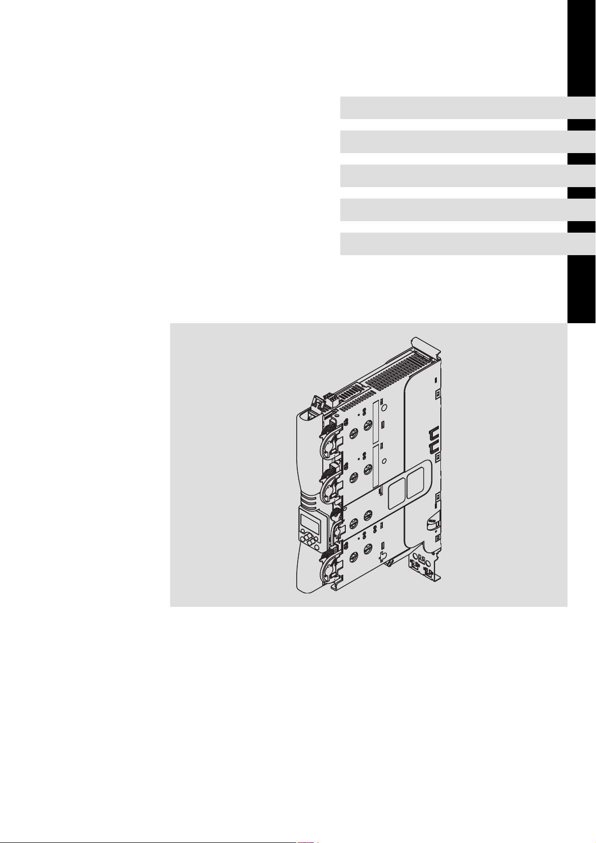
9400SSP022
Page 4
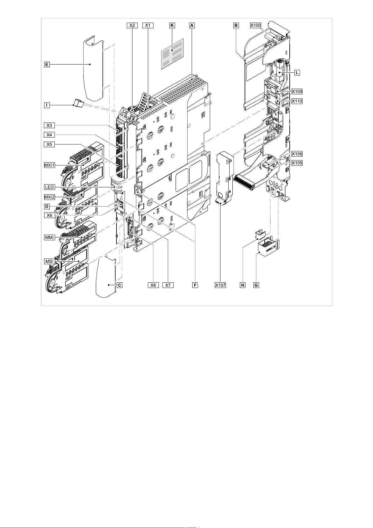
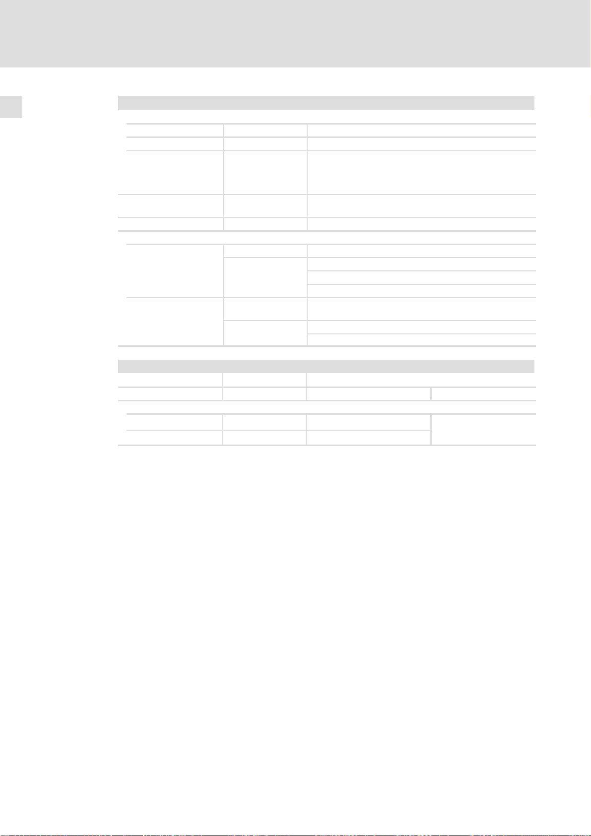
Übersicht
Grundgerät Ausführung
Pos. Beschreibung HighLine StateLine
MXI1 Modulschacht für Erweiterung 1, z. B. Kommunikation þ þ
MXI2 Modulschacht für Erweiterung 2, z. B. Kommunikation þ o
MMI Modulschacht für Speichermodule þ þ
MSI Modulschacht für Sicherheitstechnik þ þ
X1 Systembus (CAN), unter der Abdeckung þ o
X2 24−V−Versorgung und Statebus þ þ
X3 analoge Eingänge und analoge Ausgänge 2/2 1/0
X4 digitale Ausgänge 4 1
X5 digitale Eingänge 8 4
X6 Diagnose þ þ
X7 Resolver þ þ
X8 Encoder þ þ
Abdeckkappe unten þ þ
Typenschild, herausziehbar þ þ
Abdeckkappe oben þ þ
EMV−Klemmschelle 1 1
Aufkleber mit Warnhinweis − gut sichtbar nahe am Gerät anbringen! þ þ
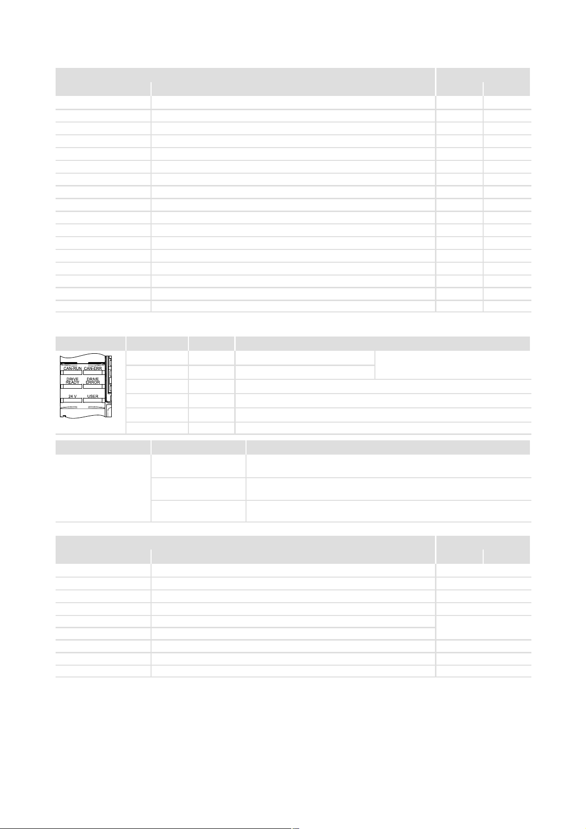
Hinweise zu einigen Betriebszuständen erhalten Sie schnell über die LED−Anzeige.
LED Beschriftung Farbe Beschreibung
CAN−RUN grün CAN−BUS o.k.
CAN−ERR rot CAN−BUS−Fehler
DRIVE READY grün Grundgerät betriebsbereit
DRIVE ERROR rot Fehler im Grundgerät oder durch die Anwendung
24 V grün 24−V−Versorgungsspannung o.k.
SSP94LED01
Pos. Symbol Beschreibung
Montagesockel Ausführung
Pos. Beschreibung HighLine StateLine
X100 Zwischenkreisspannung (kompatibel zur Serie 9300) þ
X105 Motor þ
X106 Motortemperaturüberwachung þ
X107 Ansteuerung der Motorhaltebremse optional
X109 Zwischenkreisstromschiene +
X110 Zwischenkreisstromschiene −
EMV−Klemmbügel (für Gerätegröße 2 + 3), ersetzt 1 x 1
EMV−Schirmschelle 3 bzw. 2
Schmelzsicherung für den Zwischenkreis þ
USER gelb durch die Anwendung parametrierte Meldung
0Abb. 0Tab. 0
Lange Entladezeit: Alle Leistungsklemmen führen bis zu 3 Minuten nach
Netz−Ausschalten gefährliche Spannung!
Hoher Ableitstrom: Festinstallation und PE−Anschluss nach EN 61800−5−1
ausführen!
Elektrostatisch gefährdete Bauelemente: Vor Arbeiten am Gerät muss sich
das Personal von elektrostatischen Aufladungen befreien!
ohne Funktion in der Ausführung "StateLine"
þ
4
EDK94AMH24 DE/EN/FR/ES/IT 3.1
Page 5

Inhalt i
1 Schnelleinstieg 6. . . . . . . . . . . . . . . . . . . . . . . . . . . . . . . . . . . . . . . . . . . . . . . . . . . . . . . . . . .
2 Sicherheitshinweise 7. . . . . . . . . . . . . . . . . . . . . . . . . . . . . . . . . . . . . . . . . . . . . . . . . . . . . . . .
2.1 Allgemeine Sicherheits− und Anwendungshinweise für Lenze−Antriebsregler 7. . .
2.2 Restgefahren 10. . . . . . . . . . . . . . . . . . . . . . . . . . . . . . . . . . . . . . . . . . . . . . . . . . . . . . . .
2.3 Verwendete Hinweise 11. . . . . . . . . . . . . . . . . . . . . . . . . . . . . . . . . . . . . . . . . . . . . . . . .
2.4 Sicherheitshinweise für die Installation nach UL oder UR 12. . . . . . . . . . . . . . . . . . . .
3 Technische Daten 13. . . . . . . . . . . . . . . . . . . . . . . . . . . . . . . . . . . . . . . . . . . . . . . . . . . . . . . . . .
3.1 Allgemeine Daten und Einsatzbedingungen 13. . . . . . . . . . . . . . . . . . . . . . . . . . . . .
3.2 Elektrische Daten 15. . . . . . . . . . . . . . . . . . . . . . . . . . . . . . . . . . . . . . . . . . . . . . . . . . . . .
3.3 Abmessungen 17. . . . . . . . . . . . . . . . . . . . . . . . . . . . . . . . . . . . . . . . . . . . . . . . . . . . . . .
4 Schaltungsbeispiel 18. . . . . . . . . . . . . . . . . . . . . . . . . . . . . . . . . . . . . . . . . . . . . . . . . . . . . . . . .
5 Montagesockel montieren und verdrahten 19. . . . . . . . . . . . . . . . . . . . . . . . . . . . . . . . . . . .
6 Grundgerät montieren 20. . . . . . . . . . . . . . . . . . . . . . . . . . . . . . . . . . . . . . . . . . . . . . . . . . . . .
7 Grundgerät verdrahten 21. . . . . . . . . . . . . . . . . . . . . . . . . . . . . . . . . . . . . . . . . . . . . . . . . . . . .
8 Gerätemodule verdrahten 27. . . . . . . . . . . . . . . . . . . . . . . . . . . . . . . . . . . . . . . . . . . . . . . . . .
8.1 Kommunikationsmodule 27. . . . . . . . . . . . . . . . . . . . . . . . . . . . . . . . . . . . . . . . . . . . . .
8.2 Funktionsmodule 32. . . . . . . . . . . . . . . . . . . . . . . . . . . . . . . . . . . . . . . . . . . . . . . . . . . . .
8.3 Speichermodule 34. . . . . . . . . . . . . . . . . . . . . . . . . . . . . . . . . . . . . . . . . . . . . . . . . . . . . .
8.4 Sicherheitsmodule 37. . . . . . . . . . . . . . . . . . . . . . . . . . . . . . . . . . . . . . . . . . . . . . . . . . . .
9 Abschließende Arbeiten 44. . . . . . . . . . . . . . . . . . . . . . . . . . . . . . . . . . . . . . . . . . . . . . . . . . . .
9.1 Inbetriebnahme vorbereiten 44. . . . . . . . . . . . . . . . . . . . . . . . . . . . . . . . . . . . . . . . . . .
EDK94AMH24 DE/EN/FR/ES/IT 3.1
5
Page 6

Schnelleinstieg1
1 Schnelleinstieg
So gehen Sie bei der Montage vor:
1. Lesen Sie die Sicherheitshinweise à ab Seite 7
2. Informieren Sie sich über die technischen
Daten
3. Montagesockel in den Schaltschrank
einbauen und verdrahten
4. Grundgerät in den Montagesockel
stecken
5. Grundgerät verdrahten à ab Seite 21
6. Gerätemodule einstellen und verdrahten
– Kommunikationsmodule verdrahten.
– Speichermodule einstellen.
– Sicherheitsmodule verdrahten.
à ab Seite 13
à ab Seite 19
à ab Seite 20
à ab Seite 27
7. Abschließende Arbeiten à ab Seite 44
Tipp!
Dokumentationen und Software−Updates zu weiteren Lenze Produkten finden
Sie im Internet im Bereich "Services & Downloads" unter
http://www.Lenze.com
6
EDK94AMH24 DE/EN/FR/ES/IT 3.1
Page 7

Sicherheitshinweise
Allgemeine Sicherheits− und Anwendungshinweise für Lenze−Antriebsregler
2 Sicherheitshinweise
2.1 Allgemeine Sicherheits− und Anwendungshinweise für Lenze−Antriebsregler
(gemäß Niederspannungsrichtlinie 2006/95/EG)
Allgemein
Lenze−Antriebsregler (Frequenzumrichter, Servo−Umrichter, Stromrichter) und zugehörige Komponenten können während des Betriebs − ihrer Schutzart entsprechend − spannungsführende, auch bewegliche oder rotierende Teile haben. Oberflächen können heiß
sein.
Bei unzulässigem Entfernen der erforderlichen Abdeckung, bei unsachgemäßem Einsatz,
bei falscher Installation oder Bedienung besteht die Gefahr von schweren Personen− oder
Sachschäden.
Weitere Informationen entnehmen Sie der Dokumentation.
2
Alle Arbeiten zum Transport, zur Installation, zur Inbetriebnahme und zur Instandhaltung
darf nur qualifiziertes Fachpersonal ausführen (IEC 364 bzw. CENELEC HD 384 oder
DIN VDE 0100 und IEC−Report 664 oder DIN VDE 0110 und nationale Unfallverhütungsvorschriften beachten).
Qualifiziertes Fachpersonal im Sinne dieser grundsätzlichen Sicherheitshinweise sind Personen, die mit Aufstellung, Montage, Inbetriebsetzung und Betrieb des Produkts vertraut
sind und die über die ihrer Tätigkeit entsprechenden Qualifikationen verfügen.
Bestimmungsgemäße Verwendung
Antriebsregler sind Komponenten, die zum Einbau in elektrische Anlagen oder Maschinen
bestimmt sind. Sie sind keine Haushaltsgeräte, sondern als Komponenten ausschließlich
für die Verwendung zur gewerblichen Nutzung bzw. professionellen Nutzung im Sinne der
EN 61000−3−2 bestimmt.
Bei Einbau der Antriebsregler in Maschinen ist die Inbetriebnahme (d. h. die Aufnahme des
bestimmungsgemäßen Betriebs) solange untersagt, bis festgestellt wurde, dass die Maschine den Bestimmungen der EG−Richtlinie 98/37/EG (Maschinenrichtlinie) entspricht;
EN 60204 beachten.
Die Inbetriebnahme (d. h. die Aufnahme des bestimmungsgemäßen Betriebs) ist nur bei
Einhaltung der EMV−Richtlinie (2004/108/EG) erlaubt.
Die Antriebsregler erfüllen die Anforderungen der Niederspannungsrichtlinie
2006/95/EG. Die harmonisierte Norm EN 61800−5−1 wird für die Antriebsregler angewendet.
Die technischen Daten und die Angaben zu Anschlussbedingungen entnehmen Sie dem
Leistungsschild und der Dokumentation. Halten Sie diese unbedingt ein.
Warnung: Die Antriebsregler sind Produkte, die nach EN 61800−3 für die Anwendung in einer Industrieumgebung vorgesehen sind. Beim Einsatz an öffentlichen Netzen sind zusätzliche Maßnahmen zu treffen, um die zu erwartenden Funkstörungen zu begrenzen.
EDK94AMH24 DE/EN/FR/ES/IT 3.1
7
Page 8

2
Sicherheitshinweise
Allgemeine Sicherheits− und Anwendungshinweise für Lenze−Antriebsregler
Transport und Einlagerung
Beachten Sie die Hinweise für Transport, Lagerung und sachgemäße Handhabung.
Halten Sie die klimatischen Bedingungen gemäß den technischen Daten ein.
Aufstellung
Sie müssen die Antriebsregler nach den Vorschriften der zugehörigen Dokumentation aufstellen und kühlen.
Sorgen Sie für sorgfältige Handhabung und vermeiden Sie mechanische Überlastung. Verbiegen Sie bei Transport und Handhabung weder Bauelemente noch ändern Sie Isolationsabstände. Berühren Sie keine elektronischen Bauelemente und Kontakte.
Antriebsregler enthalten elektrostatisch gefährdete Bauelemente, die Sie durch unsachgemäße Handhabung leicht beschädigen können. Beschädigen oder zerstören Sie keine
elektrischen Komponenten, da Sie dadurch Ihre Gesundheit gefährden können!
Elektrischer Anschluss
Beachten Sie bei Arbeiten an unter Spannung stehenden Antriebsreglern die geltenden
nationalen Unfallverhütungsvorschriften (z. B. VBG 4).
Führen Sie die elektrische Installation nach den einschlägigen Vorschriften durch (z. B. Leitungsquerschnitte, Absicherungen, Schutzleiteranbindung). Zusätzliche Hinweise enthält die Dokumentation.
Die Dokumentation enthält Hinweise für die EMV−gerechte Installation (Schirmung, Erdung, Anordnung von Filtern und Verlegung der Leitungen). Beachten Sie diese Hinweise
ebenso bei CE−gekennzeichneten Antriebsreglern. Der Hersteller der Anlage oder Maschine ist verantwortlich für die Einhaltung der im Zusammenhang mit der EMV−Gesetzgebung geforderten Grenzwerte. Um die am Einbauort geltenden Grenzwerte für Funkstöraussendungen einzuhalten, müssen Sie die Antriebsregler in Gehäuse
(z. B. Schaltschränke) einbauen. Die Gehäuse müssen einen EMV−gerechten Aufbau ermöglichen. Achten Sie besonders darauf, dass z. B. Schaltschranktüren möglichst umlaufend metallisch mit dem Gehäuse verbunden sind. Öffnungen oder Durchbrüche durch
das Gehäuse auf ein Minimum reduzieren.
Lenze−Antriebsregler können einen Gleichstrom im Schutzleiter verursachen. Wird für den
Schutz bei einer direkten oder indirekten Berührung ein Differenzstromgerät (RCD) verwendet, ist auf der Stromversorgungsseite des Antriebsreglers nur ein Differenzstromgerät (RCD) vom Typ B zulässig. Anderenfalls muss eine andere Schutzmaßnahme angewendet werden, wie z. B. Trennung von der Umgebung durch doppelte oder verstärkte
Isolierung oder Trennung vom Versorgungsnetz durch einen Transformator.
8
EDK94AMH24 DE/EN/FR/ES/IT 3.1
Page 9

Sicherheitshinweise
Allgemeine Sicherheits− und Anwendungshinweise für Lenze−Antriebsregler
Betrieb
Sie müssen Anlagen mit eingebauten Antriebsreglern ggf. mit zusätzlichen Überwachungs− und Schutzeinrichtungen gemäß den jeweils gültigen Sicherheitsbestimmungen
ausrüsten (z. B. Gesetz über technische Arbeitsmittel, Unfallverhütungsvorschriften). Sie
dürfen die Antriebsregler an Ihre Anwendung anpassen. Beachten Sie dazu die Hinweise
in der Dokumentation.
Nachdem der Antriebsregler von der Versorgungsspannung getrennt ist, dürfen Sie spannungsführende Geräteteile und Leistungsanschlüsse nicht sofort berühren, weil Kondensatoren aufgeladen sein können. Beachten Sie dazu die entsprechenden Hinweisschilder
auf dem Antriebsregler.
Halten Sie während des Betriebs alle Schutzabdeckungen und Türen geschlossen.
Hinweis für UL−approbierte Anlagen mit eingebauten Antriebsreglern: UL warnings sind
Hinweise, die nur für UL−Anlagen gelten. Die Dokumentation enthält spezielle Hinweise zu
UL.
Sicherheitsfunktionen
2
Bestimmte Varianten der Antriebsregler unterstützen Sicherheitsfunktionen (z. B. "Sicher
abgeschaltetes Moment", ehem. "Sicherer Halt") nach den Anforderungen von Anhang I
Nr. 1.2.7 der EG−Richtlinie "Maschinen" 98/37/EG, IEC 61508,EN 954−1 und EN 1037.
Beachten Sie unbedingt die Hinweise zu den Sicherheitsfunktionen in der Dokumentation
zu den Varianten.
Wartung und Instandhaltung
Die Antriebsregler sind wartungsfrei, wenn die vorgeschriebenen Einsatzbedingungen
eingehalten werden.
Bei verunreinigter Umgebungsluft können die Kühlflächen des Antriebsreglers verschmutzen oder Kühlöffnungen verstopft werden. Bei diesen Betriebsbedingungen deshalb regelmäßig die Kühlflächen und Kühlöffnungen reinigen. Dazu niemals scharfe oder
spitze Gegenstände verwenden!
Entsorgung
Metalle und Kunststoffe zur Wiederverwertung geben. Bestückte Leiterplatten fachgerecht entsorgen.
Beachten Sie unbedingt die produktspezifischen Sicherheits− und Anwendungshinweise
in dieser Anleitung!
EDK94AMH24 DE/EN/FR/ES/IT 3.1
9
Page 10

2
Sicherheitshinweise
Restgefahren
2.2 Restgefahren
Personenschutz
ƒ Überprüfen Sie vor Arbeiten am Antriebsregler, ob alle Leistungsklemmen
spannungslos sind, da
– nach dem Netzabschalten die Leistungsklemmen U, V, W, +UG und −UG noch bis
zu 3 Minuten gefährliche Spannung führen.
– bei gestopptem Motor die Leistungsklemmen U, V, W, +UG und −UG gefährliche
Spannung führen.
Geräteschutz
ƒ Alle steckbaren Anschlussklemmen nur im spannungslosen Zustand aufstecken oder
abziehen!
ƒ Die Antriebsregler nur im spannungslosen Zustand aus der Installation, z. B. aus
dem Montagesockel oder Schaltschrankrückwand, trennen!
ƒ Zyklisches Ein− und Ausschalten der Netzspannung kann die
Eingangsstrombegrenzung des Antriebsreglers überlasten und zerstören:
– Zyklisches Netzschalten von 5−mal in 5 Minuten ist uneingeschränkt zulässig.
Motorschutz
ƒ Bei bestimmten Einstellungen der Antriebsregler kann der angeschlossene Motor
überhitzt werden:
– Z. B. längerer Betrieb der Gleichstrombremse.
– Längerer Betrieb eigenbelüfteter Motoren bei kleinen Drehzahlen.
Schutz der Maschine/Anlage
ƒ Antriebe können gefährliche Überdrehzahlen erreichen (z. B. Einstellung hoher
Ausgangsfrequenzen bei dafür ungeeigneten Motoren und Maschinen):
– Die Antriebsregler bieten keinen Schutz gegen solche Betriebsbedingungen.
Setzen Sie dafür zusätzliche Komponenten ein.
10
EDK94AMH24 DE/EN/FR/ES/IT 3.1
Page 11

Sicherheitshinweise
Verwendete Hinweise
2
2.3 Verwendete Hinweise
Um auf Gefahren und wichtige Informationen hinzuweisen, werden in dieser Dokumentation folgende Piktogramme und Signalwörter verwendet:
Sicherheitshinweise
Aufbau der Sicherheitshinweise:
Gefahr!
(kennzeichnet die Art und die Schwere der Gefahr)
Hinweistext
(beschreibt die Gefahr und gibt Hinweise, wie sie vermieden werden kann)
Piktogramm und Signalwort Bedeutung
Gefahr!
Gefahr!
Stop!
Gefahr von Personenschäden durch gefährliche elektrische
Spannung
Hinweis auf eine unmittelbar drohende Gefahr, die den Tod oder
schwere Verletzungen zur Folge haben kann, wenn nicht die
entsprechenden Maßnahmen getroffen werden.
Gefahr von Personenschäden durch eine allgemeine Gefahrenquelle
Hinweis auf eine unmittelbar drohende Gefahr, die den Tod oder
schwere Verletzungen zur Folge haben kann, wenn nicht die
entsprechenden Maßnahmen getroffen werden.
Gefahr von Sachschäden
Hinweis auf eine mögliche Gefahr, die Sachschäden zur Folge
haben kann, wenn nicht die entsprechenden Maßnahmen getroffen werden.
Anwendungshinweise
Piktogramm und Signalwort Bedeutung
Hinweis!
Tipp!
Spezielle Sicherheitshinweise und Anwendungshinweise für UL und UR
Piktogramm und Signalwort Bedeutung
Warnings!
Warnings!
Wichtiger Hinweis für die störungsfreie Funktion
Nützlicher Tipp für die einfache Handhabung
Verweis auf andere Dokumentation
Sicherheitshinweis oder Anwendungshinweis für den Betrieb
eines UL−approbierten Geräts in UL−approbierten Anlagen.
Möglicherweise wird das Antriebssystem nicht UL−gerecht betrieben, wenn nicht die entsprechenden Maßnahmen getroffen
werden.
Sicherheitshinweis oder Anwendungshinweis für den Betrieb
eines UR−approbierten Geräts in UL−approbierten Anlagen.
Möglicherweise wird das Antriebssystem nicht UL−gerecht betrieben, wenn nicht die entsprechenden Maßnahmen getroffen
werden.
EDK94AMH24 DE/EN/FR/ES/IT 3.1
11
Page 12

2
Sicherheitshinweise
Sicherheitshinweise für die Installation nach UL oder UR
2.4 Sicherheitshinweise für die Installation nach UL oder U
Warnings!
ƒ The integral solid state protection does not provide branch circuit protection
and that branch circuit protection has to be provided externally in
accordance with manufacturers instructions, the National Electrical Code
and any additional codes.
ƒ For information on the protection level of the internal overload protection
for a motor load, see the corresponding Application Manuals or Software
Helps.
ƒ For information on rating and proper connection of the thermal protector
(only for connection to motors having integral thermal protection), see the
corresponding Application Manuals or Software Helps.
ƒ Maximum surrounding air temperature: 55 °C.
ƒ Use 60/75 °C copper wire only, except for control circuits.
ƒ Control card protection:
External fuse for 24 Vdc supply voltage of control terminal X2. Rated 4 A DC
fuse UL248−14.
R
12
EDK94AMH24 DE/EN/FR/ES/IT 3.1
Page 13
Allgemeine Daten und Einsatzbedingungen
3 Technische Daten
3.1 Allgemeine Daten und Einsatzbedingungen
Angaben zu Netzen
Netzformen
Störaussendung EN 61800−3
Störfestigkeit EN 61800−3 Kategorie C3
Konformität und Approbation
Konformität
CE
Approbation
UL UL 508C Power Conversion Equipment, File No. 132659
GOST−R 51321.1−2000
mit geerdetem Y−
Punkt
IT−Netze Anweisungen über besondere Maßnahmen beachten!
2006/95/EG Niederspannungsrichtlinie
51321.3−99
uneingeschränkte Nutzung
leitungsgeführt: keine Angabe möglich, da abhängig von den
Gegebenheiten im Verbund
Strahlung: Kategorie C3
No. POCC DE.AN30.B08815
Technische Daten
3
Personenschutz und Geräteschutz
Schutzart
Isolationsfestigkeit EN 61800−5−1 Überspannungskategorie III
Isolation von Steuerschaltkreisen
Kurzschlussfestigkeit EN 61800−5−1 Motoranschluss: bedingt, Fehlerquittierung erforderlich
Motor−Schutzmaßnahmen
gegen
Ableitstrom EN 61800−5−1 > 3,5 mA AC, > 10 mA DC Bestimmungen und
Zyklisches Netzschalten Zyklisches Netzschalten von 5−mal in 5 Minuten ist uneinge-
EN 60529
NEMA 250 Berührschutz nach Typ 1
EN 61800−5−1 Sichere Trennung vom Netz durch doppelte/verstärkte
IP 20
Reduzierung ab 2000 m ü. NN: Überspannungskategorie II
Isolierung für sternpunktgeerdete Netze mit einer Bemessungsspannung Außenleiter/Sternpunkt bis 300 V.
Steueranschlüsse: voll
l Kurzschluss
l Erdschluss
l Überspannung
l Kippen des Motors
l Übertemperatur des Motors
(PTC oder Thermokontakt, I
schränkt zulässig.
nicht im Anschlussbereich
der motorseitigen Klemmen
2
t−Überwachung)
Sicherheitshinweise
beachten!
EDK94AMH24 DE/EN/FR/ES/IT 3.1
13
Page 14
3
Technische Daten
Allgemeine Daten und Einsatzbedingungen
Umweltbedingungen
Klima
Lagerung
Transport IEC/EN 60721−3−2 2K3 (−25 ... +70 °C)
Betrieb IEC/EN 60721−3−3 3K3 (−10 ... +55 °C)
Aufstellhöhe 0 ... 4000 m üNN
Verschmutzung IEC/EN 60664−1 Verschmutzungsgrad 2
Rüttelfestigkeit (9,81 m/s
Transport
Betrieb
IEC/EN 60721−3−1 1K3 (−25 ... +60 °C)
Stromreduzierung von +45 ... +55 °C:
Gerätegröße 1 ... 7: 2.5 %/°C
Gerätegröße 8S ... 10: 1 %/°C
1000 ... 4000 m üNN: Stromreduzierung 5 %/1000 m
2
= 1 g)
IEC/EN 60721−3−2 2M2
EN 61800−2
Germanischer Lloyd 5 ... 13.2 Hz: Amplitude ±1 mm
IEC/EN 60068−2−6
2 ... 9 Hz: Amplitude 3.5 mm
10 ... 200 Hz: beschleunigungsfest bis 10 m/s
200 ... 500 Hz: beschleunigungsfest bis 15 m/s
13.2 ... 100 Hz: beschleunigungsfest bis 0.7 g
10 ... 57 Hz: Amplitude 0.075 mm
57 ... 150 Hz: beschleunigungsfest bis 10 m/s
2
2
2
Montagebedingungen
Einbauort
Einbaulage vertikal
Einbaufreiräume
oberhalb/unterhalb
seitlich
im Schaltschrank
³ 80 mm / ³ 120 mm
ohne Abstand anreihbar
Beachten Sie gerätebezogene Angaben zur Montage.
14
EDK94AMH24 DE/EN/FR/ES/IT 3.1
Page 15

Technische Daten
Elektrische Daten
3
3.2 Elektrische Daten
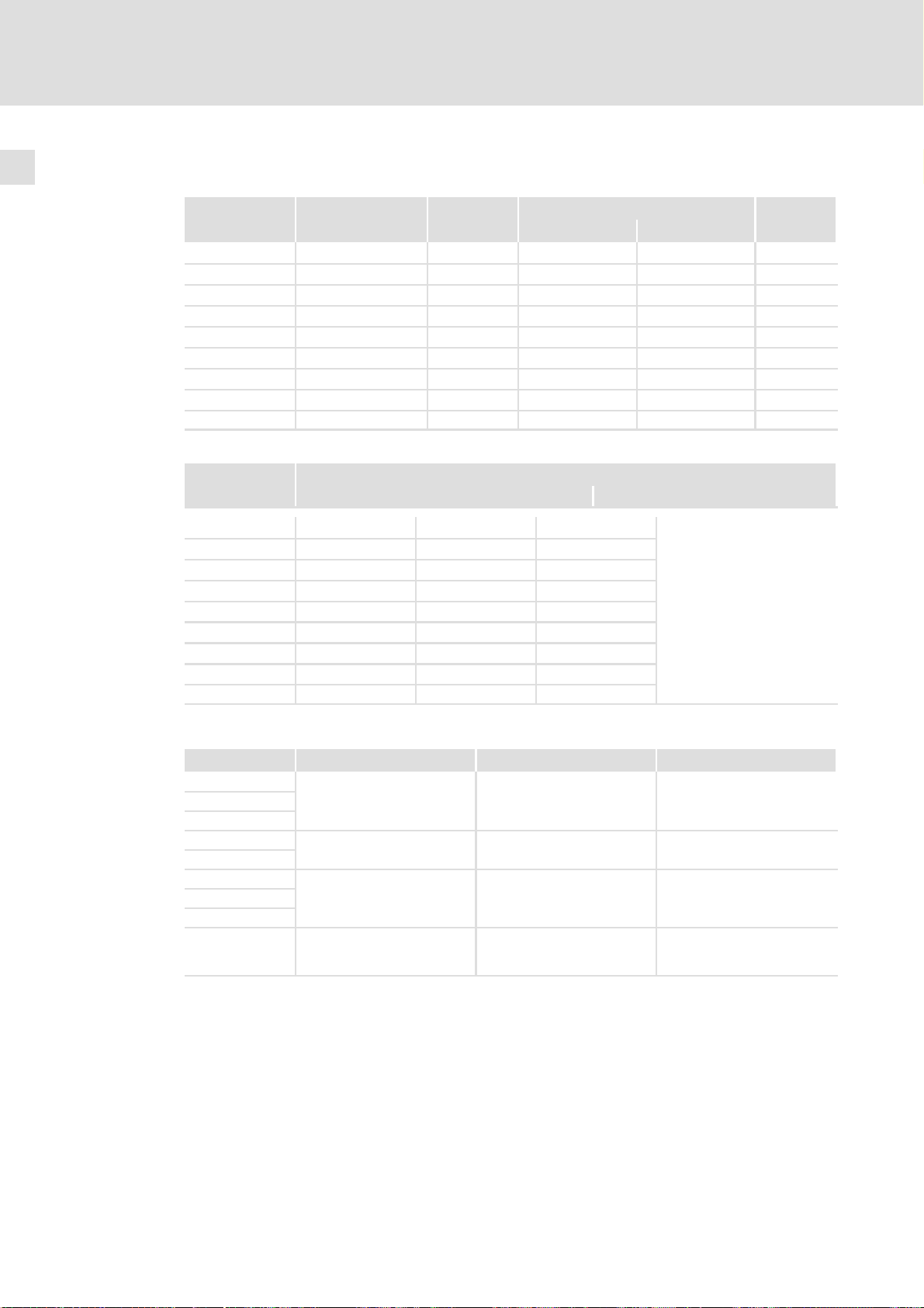
Eingangsdaten
Grundlage der Daten
Netz Spannung
2/PE DC 325 260 − 0 % ... 370 + 0 % −
2/PE DC 565 455 − 0 % ... 620 + 0 % −
2/PE DC 705 565 − 0 % ... 775 + 0 % −
E94AMxE0024 325/565/705 0 ( DC) 2.6/2.6/2.3 2.0/2.0/1.7 2
E94AMxE0034 325/565/705 0 ( DC) 4.3/4.3/3.8 3.2/3.2/2.9 2
E94AMxE0044 325/565/705 0 ( DC) 6.7/6.7/5.9 5.0/5.0/4.4 2
E94AMxE0074 325/565/705 0 ( DC) 12.1/12.1/10.6 9.1/9.1/8.0 2
E94AMxE0094 325/565/705 0 ( DC) 15.4/15.4/13.5 11.6/11.6/10.1 2
E94AMxE0134 325/565/705 0 ( DC) 20.6/20.6/18.0 15.5/15.5/13.5 2
E94AMxE0174 325/565/705 0 ( DC) 25.7/25.7/22.5 19.3/19.3/16.9 2
E94AMxE0244 325/565/705 0 ( DC) 35.5/35.5/31.1 26.3/26.3/23.3 2
E94AMxE0324 325/565/705 0 ( DC) 48.0/48.0/38.9 36.0/36.0/29.1 2
Temperatur im Schaltschrank
Spannungsbereich
UDC [V]
Spannung Frequenz Strom [A]
[V] [Hz] bis +45 °C bis +55 °C
UDC [V]
Frequenzbereich
f [Hz]
Phasenzahl
EDK94AMH24 DE/EN/FR/ES/IT 3.1
15
Page 16
3
Technische Daten
Elektrische Daten
Ausgangsdaten
Spannung Frequenz
Typ [V] [Hz] bis +45 °C
E94AMxE0024 0 − 230/400/500 0 − 599 1.5/1.5/1.3 1.1/1.1/1.0 3
E94AMxE0034 0 − 230/400/500 0 − 599 2.5/2.5/2.2 1.9/1.9/1.7 3
E94AMxE0044 0 − 230/400/500 0 − 599 4/4/3.5 3/3/2.6 3
E94AMxE0074 0 − 230/400/500 0 − 599 7/7/6.1 5.3/5.3/4.6 3
E94AMxE0094 0 − 230/400/500 0 − 599 9.3/9.3/8.2 7.0/7.0/6.2 3
E94AMxE0134 0 − 230/400/500 0 − 599 13/13/11.4 9.8/9.8/8.6 3
E94AMxE0174 0 − 230/400/500 0 − 599 16.5/16.5/14.4 12.4/12.4/10.8 3
E94AMxE0244 0 − 230/400/500 0 − 599 23.5/23.5/20.6 17.6/17.6/15.5 3
E94AMxE0324 0 − 230/400/500 0 − 599 32.0/32.0/25.9 24.0/24.0/19.4 3
Temperatur im Schaltschrank
Typ bei Betrieb mit Ausgangsbemessungsstrom I
1)
Verlustleistung PV [W]
aN
Strom [A]
bis +55 °C
bei Reglersperre
Phasenzahl
E94AMxE0024 65 80 95
E94AMxE0034 75 95 110
E94AMxE0044 90 120 130
E94AMxE0074 105 145 170
E94AMxE0094 130 170 205
E94AMxE0134 160 215 255
E94AMxE0174 185 255 300
E94AMxE0244 235 320 385
E94AMxE0324 290 405 490
40
Zuordnung Montagesockel ˘ Grundgerät
Achsregler−Typ Montagesockel−Typ Schmelzsicherung Gerätegröße
E94AMxE0024
E94AMxE0034
E94AMxE0044
E94AMxE0074
E94AMxE0094
E94AMxE0134
E94AMxE0174
E94AMxE0244
E94AMxE0324 E94AZPM0324
E94AZPM0044
E94AZPM0094 Siba 5020106.40A 2
E94AZPM0244
Siba 5020106.16A 1
Siba 2029221.100A
(Anzugsdrehmoment: 3,4 Nm
(30 lb−in))
Siba 2029221.100A
(Anzugsdrehmoment: 3,4 Nm
(30 lb−in))
3
3
16
EDK94AMH24 DE/EN/FR/ES/IT 3.1
Page 17
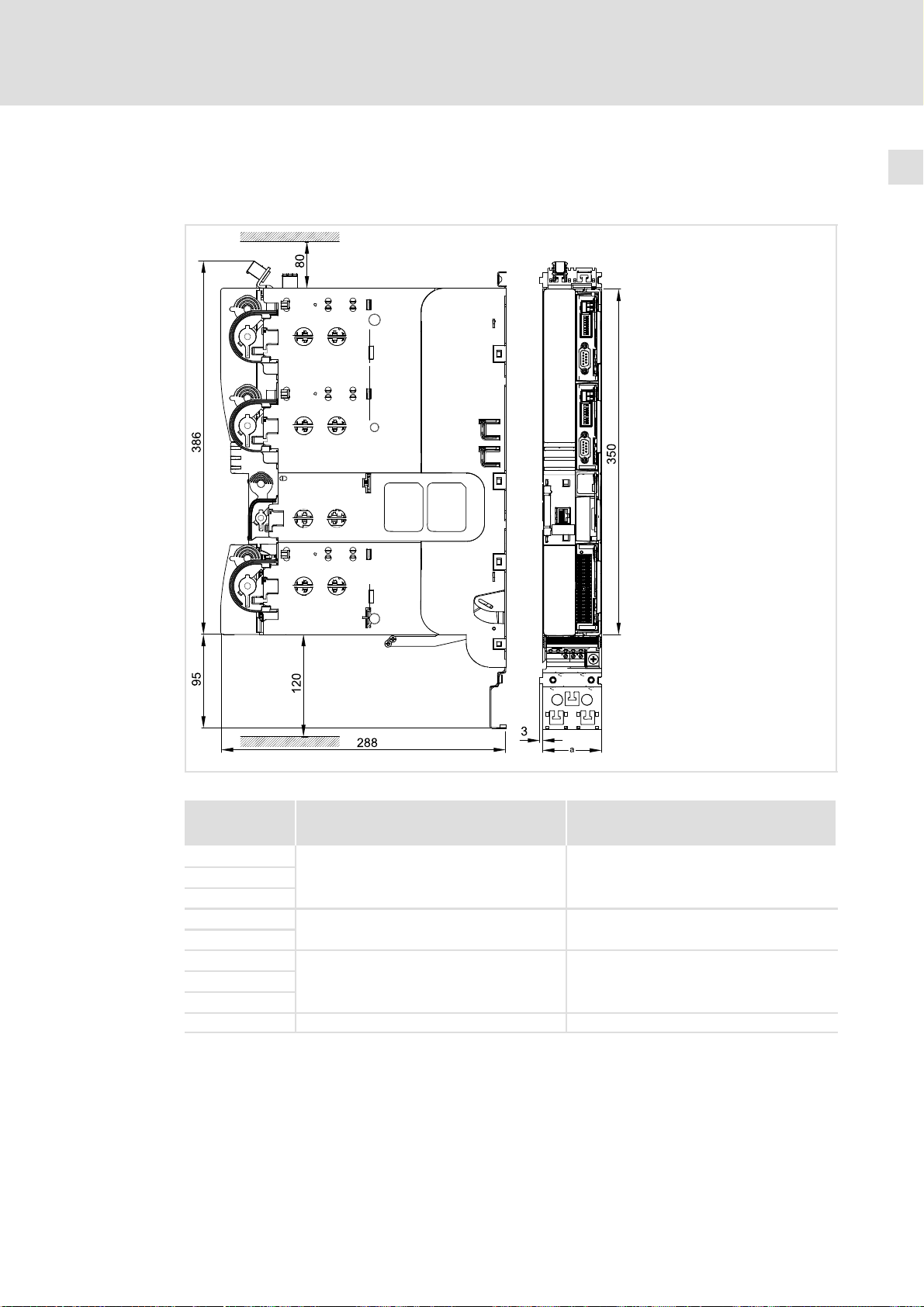
3.3 Abmessungen
Grundgerät mit Montagesockel
Technische Daten
Abmessungen
3
Abb. 3−1 Abmessungen [mm]
Abmessung a Masse
Typ [mm] [kg]
E94AMxE0024
E94AMxE0034
E94AMxE0044
E94AMxE0074
E94AMxE0094
E94AMxE0134
E94AMxE0174
E94AMxE0244
E94AMxE0324 120 8.5
60
90 5.3
120 8.1
SSP94GGmSo020
4.0
EDK94AMH24 DE/EN/FR/ES/IT 3.1
17
Page 18
Schaltungsbeispiel4
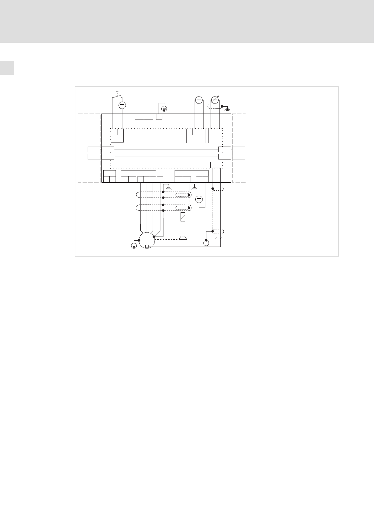
4 Schaltungsbeispiel
RFR
01
X109
X109
+UG
X110
X110
-UG
X106
T1
+
-
-UG
+UG
X100
RFR
GI
X5
E94AMxExxxx
X105 X107
T2
U
V
M
3~
J
+
E94AZPxxxxx
W
+
BD1
+
24ESB GE
X2
BD2
Y
-
-
+
A1-A1+
X3
X109
X109
X110
X110
X7
-
+
+
-
R
EYF...
7
2
SSP94PSP31
E94AMxExxxx Servo−Achsmodul 9400 Multi Drive
E94AZPxxxxx Montagesockel
DC Versorgungsmodul oder DC Einspeisestelle oder Achsmodul
weiteres Achsmodul
HF−Schirmabschluss durch großflächige Anbindung an Funktionserde
EYF... Systemleitung Resolverrückführung
RFR Regler−Freigabe
R Resolver
Y Motorhaltebremse (an optionaler Motorbremsen−Ansteuerung)
Drehzahlsollwertvorgabe über Analogeingang 1 (−10 ... 0 ... +10 V)
Spannungsquelle für die Motorhaltebremse
24−V−Spannungsquelle für die digitalen Eingänge nach IEC 61131−2
24−V−Spannungsquelle für die Steuerelektronik nach IEC 61131−2
18
EDK94AMH24 DE/EN/FR/ES/IT 3.1
Page 19

Montagesockel montieren und verdrahten 5
5 Montagesockel montieren und verdrahten
Hinweis!
Sie müssen die Geräte in Gehäuse (z. B. Schaltschränke) einbauen, um
geltende Bestimmungen zu erfüllen.
Hinweis!
Achsmodule E94AMxE0324 und Montagesockel E94AZPM0324 sind nur direkt
miteinander verwendbar! Eine Verwendung mit einem anderen Gerät bzw.
Montagesockel der Gerätegröße 3 ist nicht zulässig und wird über einen
Steckschutz verhindert.
Berücksichtigen Sie dies bereits bei der Planung von Antriebsverbünden, bei
denen die Geräte angereiht werden.
Montieren und Verdrahten des Montagesockels ist in der Montageanleitung des Montagesockels
beschrieben.
EDK94AMH24 DE/EN/FR/ES/IT 3.1
19
Page 20
Grundgerät montieren6
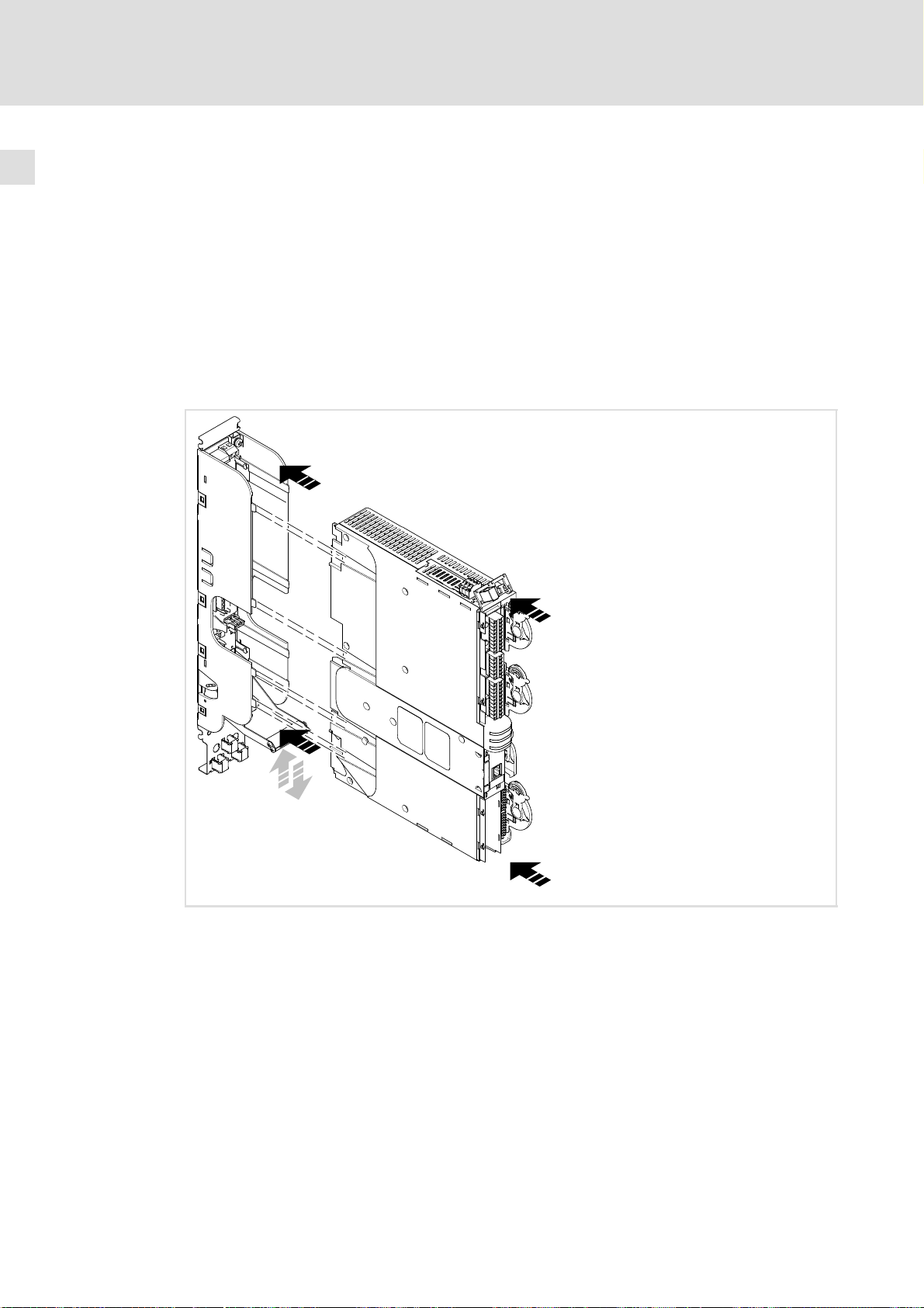
6 Grundgerät montieren
So gehen Sie vor:
1. Grundgerät ohne Verkanten in den Montagesockel einschieben, bis Gegendruck
spürbar wird.
2. Grundgerät kräftig in den Montagesockel drücken, bis es hörbar einrastet. Der
Verriegelungsbügel bewegt sich dabei nach unten und zurück in die
Verriegelungsposition.
3. Die Endposition ist erreicht, wenn der Verriegelungsbügel bis an das Grundgerät
gedrückt werden kann. Das Grundgerät ist jetzt verriegelt.
20
SSP94GG122
Abb. 6−1 Grundgerät montieren
Müssen Sie das Grundgerät noch einmal entnehmen, gehen Sie so vor:
1. Bereits verdrahtete Steckverbindungen am Grundgerät lösen.
2. Verriegelungsbügel nach unten drücken. Das Grundgerät wird damit entriegelt und
aus den Kontakten gedrückt.
3. Grundgerät vollständig aus dem Montagesockel ziehen und entnehmen. Der
Verriegelungsbügel springt zurück in die Verriegelungsposition.
EDK94AMH24 DE/EN/FR/ES/IT 3.1
Page 21

7 Grundgerät verdrahten
Gefahr!
Gefährliche elektrische Spannung
Alle Leistungsanschlüsse führen bis zu 3 Minuten nach Netz−Ausschalten
gefährliche elektrische Spannung.
Mögliche Folgen:
ƒ Tod oder schwere Verletzungen beim Berühren der Leistungsanschlüsse.
Schutzmaßnahmen:
ƒ Vor Arbeiten an den Leistungsanschlüssen Netz abschalten und mindestens
3 Minuten warten.
ƒ Prüfen, ob alle Leistungsanschlüsse spannungsfrei sind.
Grundgerät verdrahten 7
Stop!
Das Gerät enthält Bauelemente, die durch elektrostatische Entladungen
zerstört werden können!
Vor Arbeiten am Gerät muss sich das Personal durch geeignete Maßnahmen
von elektrostatischen Aufladungen befreien.
Ausführung der Leitungen
ƒ Die verwendeten Leitungen müssen den geforderten Approbationen am Einsatzort
genügen (z. B. UL).
ƒ Die Wirksamkeit einer abgeschirmten Leitung wird erreicht durch:
– Gute Schirmanbindung durch großflächige Schirmauflage herstellen.
– Nur Schirmgeflecht mit niedrigem Schirmwiderstand aus verzinntem oder
vernickeltem Kupfer−Geflecht verwenden.
– Schirmgeflecht mit Überdeckungsgrad > 70 % und Überdeckungswinkel 90 °
verwenden.
– Ungeschirmte Leitungsenden so kurz wie möglich ausführen.
Diese Anschlüsse mit Systemleitungen oder geschirmt ausführen:
ƒ Analogsignale (Ein− und Ausgänge)
ƒ Systembus CAN
ƒ Resolver
ƒ Encoder
Diese Anschlüsse können Sie ungeschirmt ausführen:
ƒ 24−V−Versorgung
ƒ Digitalsignale (Ein− und Ausgänge)
EDK94AMH24 DE/EN/FR/ES/IT 3.1
21
Page 22
Grundgerät verdrahten7
Tipp!
Parametrierung und Konfiguration führen Sie mit dem L−force »Engineer«
durch. Dabei unterstützt Sie die Online−Hilfe und das Softwarehandbuch zum
Grundgerät.
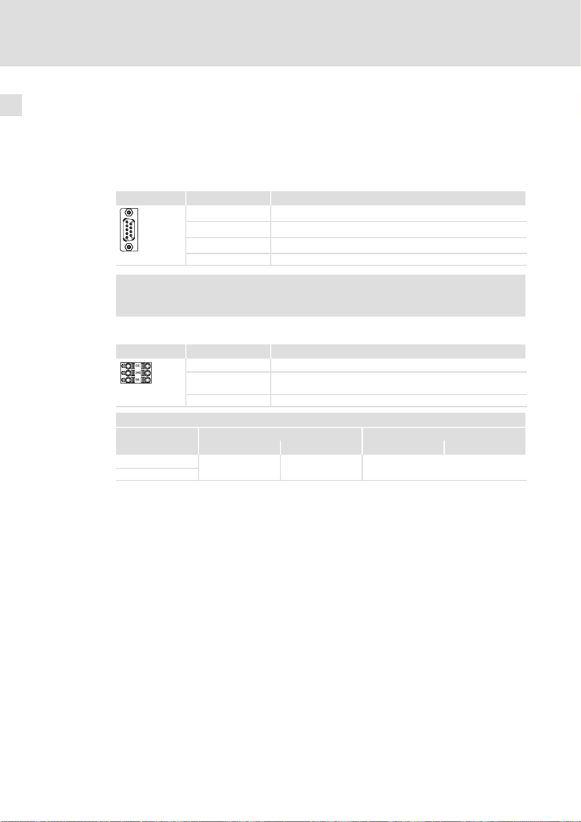
Systembus CAN on board
Klemme X1 Beschriftung Beschreibung
Pin 2 CAN−LOW
Pin 3 CAN−GND
Pin 7 CAN−HIGH
9400SSP000X1
(Gehäuse) CAN−Shield
Hinweis!
Der Anschluss X1 ist in der Ausführung "StateLine" nicht vorhanden.
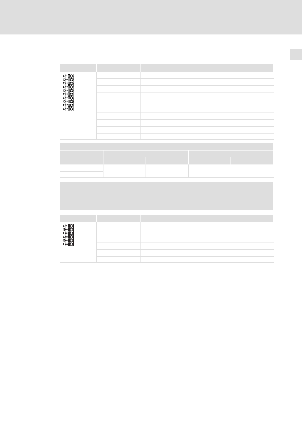
24−V−Versorgung
Klemme X2 Beschriftung Beschreibung
GE GND Externe Versorgung
9400SSP000X2
Klemmendaten
flexibel
mit Aderendhülse
24E 24 V Externe Versorgung durch ein sicher getrenntes Netzteil (SELV/
SB Statebus In/Out (Bezugspotential GE)
[mm2] [AWG] [Nm] [lb−in]
0.2 ... 2.5
PELV)
Leiterquerschnitt Anzugsmoment
24 ... 12 Federkraftklemme
22
EDK94AMH24 DE/EN/FR/ES/IT 3.1
Page 23
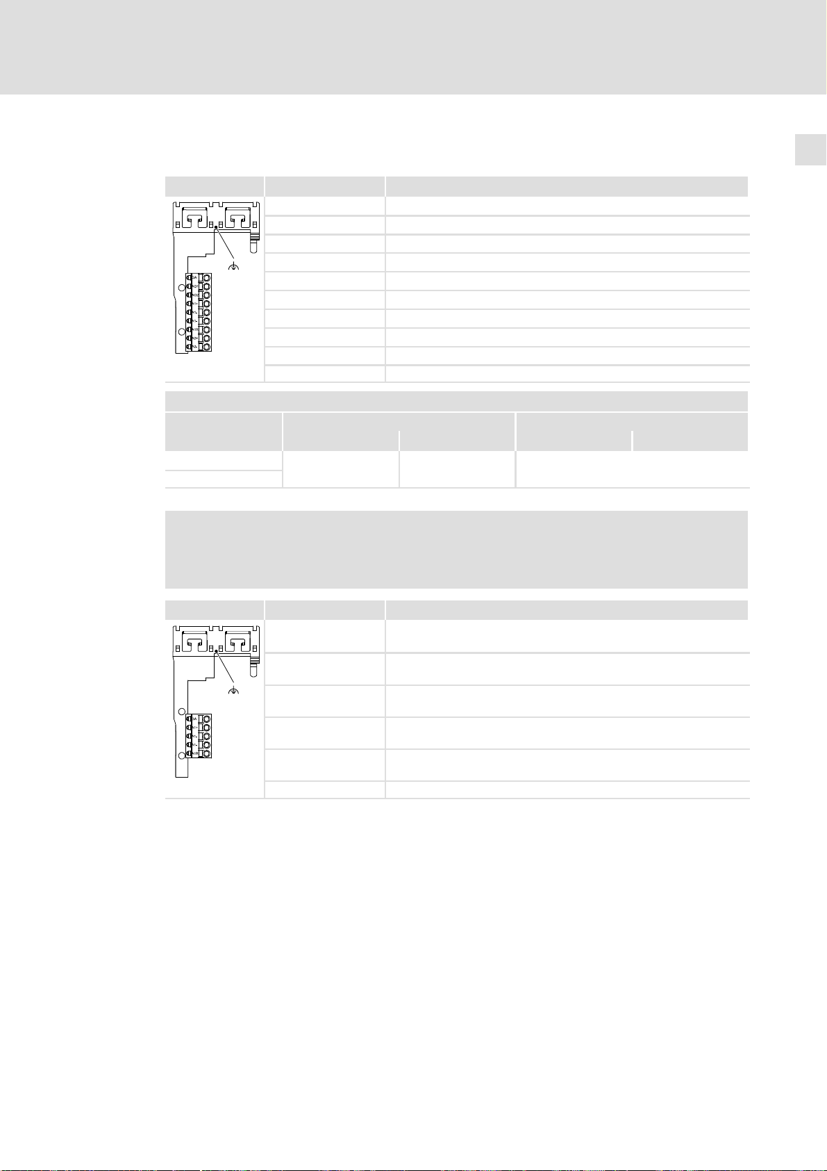
Analoge Eingänge, analoge Ausgänge
Klemme X3 Beschriftung Beschreibung
GA GND Analogsignale
AO1 Analogausgang 1
AO2 Analogausgang 2
A1+ Analogeingang 1 +
A1− Analogeingang 1 −
A1− Analogeingang 1 −
A1R Abschlusswiderstand für ±20mA
A2+ Analogeingang 2 +
A2− Analogeingang 2 −
SSP94000X3
Klemmendaten
flexibel
mit Aderendhülse
[mm2] [AWG] [Nm] [lb−in]
0.2 ... 2.5
Schirmauflage: Schirm mit EMV−Klemmbügel fixieren.
Leiterquerschnitt Anzugsmoment
24 ... 12 Federkraftklemme
Grundgerät verdrahten 7
Hinweis!
In der Ausführung "StateLine" ist dieser Anschluss in geändertem Umfang
vorhanden.
Klemme X3 Beschriftung Beschreibung
GA GND Analogsignale
A1+ Analogeingang 1 +
A1− Analogeingang 1 −
A1− Analogeingang 1 −
A1R Abschlusswiderstand für ±20mA
SSP94SL0X3
Schirmauflage: Schirm mit EMV−Klemmbügel fixieren.
EDK94AMH24 DE/EN/FR/ES/IT 3.1
23
Page 24
Grundgerät verdrahten7
Digitalausgänge
Klemme X4 Beschriftung Beschreibung
GO GND Digital out
24O 24−V−Digital out
DO1 Digitalausgang 1
DO2 Digitalausgang 2
DO3 Digitalausgang 3
9400SSP000X4
Klemmendaten
flexibel
mit Aderendhülse
DO4 Digitalausgang 4
Leiterquerschnitt Anzugsmoment
[mm2] [AWG] [Nm] [lb−in]
0.2 ... 2.5
24 ... 12 Federkraftklemme
Hinweis!
In der Ausführung "StateLine" ist dieser Anschluss in geändertem Umfang
vorhanden.
Klemme X4 Beschriftung Beschreibung
GO GND Digital out
24O 24−V−Digital out
9400SSPxxx
DO1 Digitalausgang 1
24
EDK94AMH24 DE/EN/FR/ES/IT 3.1
Page 25
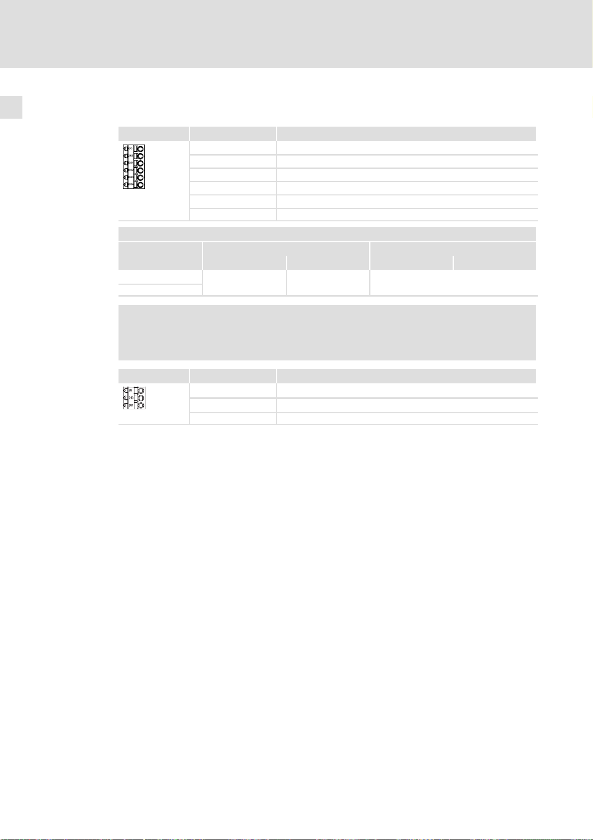
Digitaleingänge
Klemme X5 Beschriftung Beschreibung
GI GND Digital In
RFR Reglerfreigabe
DI1 Digitaleingang 1
DI2 Digitaleingang 2
DI3 Digitaleingang 3
DI4 Digitaleingang 4
DI5 Digitaleingang 5
DI6 Digitaleingang 6
DI7 Digitaleingang 7
9400SSP000X5
Klemmendaten
flexibel
mit Aderendhülse
DI8 Digitaleingang 8
Leiterquerschnitt Anzugsmoment
[mm2] [AWG] [Nm] [lb−in]
0.2 ... 2.5
24 ... 12 Federkraftklemme
Grundgerät verdrahten 7
Hinweis!
In der Ausführung "StateLine" ist dieser Anschluss in geändertem Umfang
vorhanden.
Klemme X5 Beschriftung Beschreibung
GI GND Digital In
RFR Reglerfreigabe
DI1 Digitaleingang 1
DI2 Digitaleingang 2
DI3 Digitaleingang 3
9400SSPxxx
DI4 Digitaleingang 4
EDK94AMH24 DE/EN/FR/ES/IT 3.1
25
Page 26
Grundgerät verdrahten7
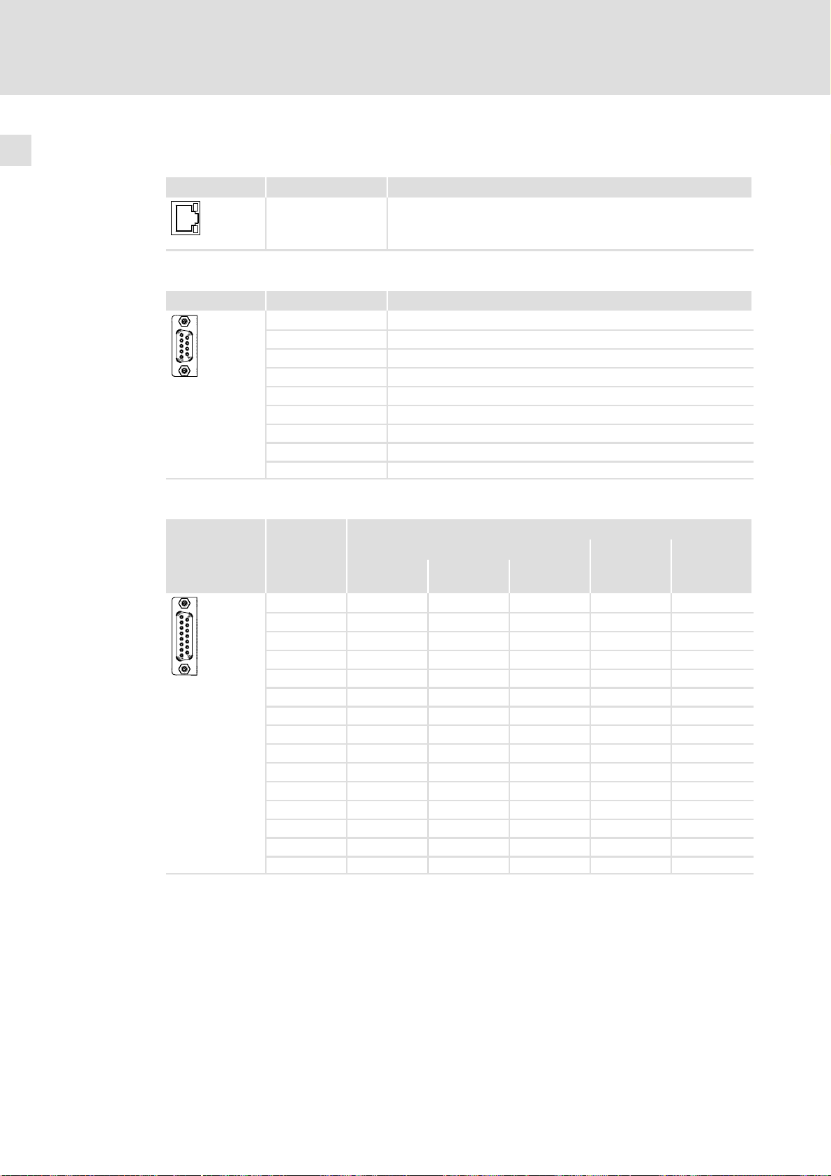
Diagnose/Keypad
Klemme X6 Beschriftung Beschreibung
interne Schnittstelle, RJ69−Buchse, für Keypad oder Diagnoseadapter
9400SSP000X6
Resolver
Klemme X7 Beschriftung Beschreibung
1 +REF
2 −REF
9400SSP000X7
3 V
4 +COS
5 −COS
6 +SIN
7 −SIN
8 +KTY
9 −KTY
CC
Encoder
Klemme X8 Pin
9400SSP000X8
Beschreibung
Leitung EYF001... EYF002... −
TTL 1 V
SS
1 V
SS
Hiperface
1 V
SS
EnDat 2.1
1 A A COS A −
2 GND GND GND GND GND
3 B B Sin B −
4 V
CC
V
CC
V
CC
V
CC
U
S
5 Z Z +RS485 Data (Z) Data +
6 n. c. n. c. n. c. n. c. n. c.
7 −KTY −KTY −KTY −KTY −
8 − − − Clock Clock +
9 /A /A Ref COS /A −
10 − − − −Sense −
11 /B /B Ref SIN /B −
12 − − − +Sense −
13 /Z /Z −RS485 /Data (/Z) Data −
14 +KTY +KTY +KTY +KTY −
15 − − − /Clock Clock −
SSI
26
EDK94AMH24 DE/EN/FR/ES/IT 3.1
Page 27
8 Gerätemodule verdrahten
Abhängig von der Geräteausführung oder der Applikation ist das Gerät mit Gerätemodulen bestückt. Die möglichen Module sind hier kurz beschrieben. Umfassende Informationen enthält die zugeordnete Dokumentation.
8.1 Kommunikationsmodule
Diese Module in Schacht þ MXI1 oder þ MXI2 o MMI o MSI verwenden.
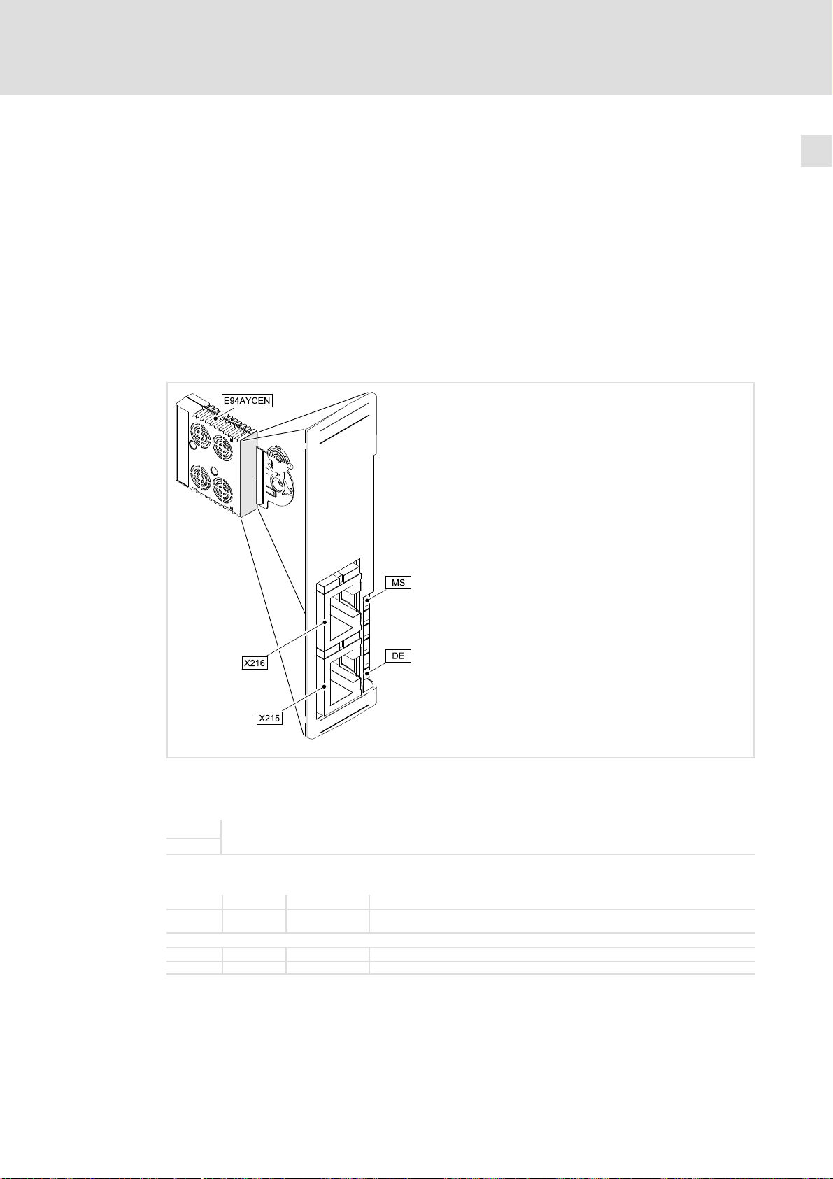
Ethernet
Gerätemodule verdrahten
Kommunikationsmodule
8
Abb. 8−1 Kommunikationsmodul E94AYCEN (Ethernet)
Anschlüsse
X215
X216
Anzeigen
MS grün an Das Kommunikationsmodul ist mit Spannung versorgt.
DE rot an Das Kommunikationsmodul wird vom Grundgerät nicht akzeptiert (siehe Hinweise in der Anleitung
LEDs am Anschluss X215/X216:
− gelb an / blinkt Daten werden über Ethernet ausgetauscht.
− grün an Ethernet−Verbindung ist vorhanden.
EDK94AMH24 DE/EN/FR/ES/IT 3.1
Ethernet−Anschlüsse
Ausführung: jeweils RJ45−Buchse nach IEC 60603−7
zum Grundgerät).
E94YCEN001A
27
Page 28
8
Gerätemodule verdrahten
Kommunikationsmodule
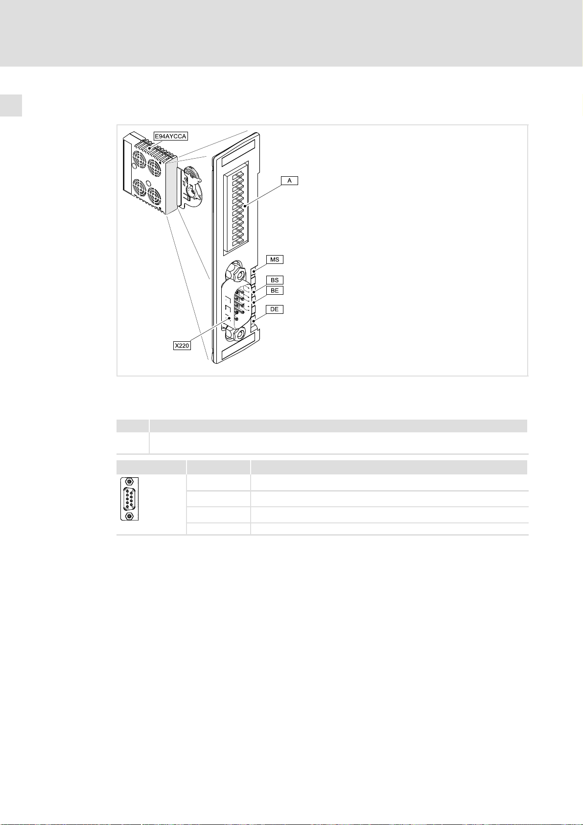
CANopen
Abb. 8−2 Kommunikationsmodul E94AYCCA (CANopen)
Anschlüsse
Pos. Beschreibung
X220 Anschluss für CAN
Ausführung: Sub−D−Stiftleiste, 9−polig
X220 Beschriftung Beschreibung
Pin 2 CAN−LOW
Pin 3 CAN−GND
Pin 7 CAN−HIGH
9400SSP000X1
(Gehäuse) CAN−Shield
E94YCCA001B
28
EDK94AMH24 DE/EN/FR/ES/IT 3.1
Page 29
DIP−Schalter
Pos. Beschreibung
Adressierung des Teilnehmers
O
N
A
643216 8
cdba
421
Gerätemodule verdrahten
Kommunikationsmodule
8
Baud
Abb. 8−3 Anordnung und Beschriftung der DIP−Schalter
CAN Address
9400CAN003
Bei den frontseitig angeordneten DIP−Schaltern können
ƒ Knotenadresse (Beschriftung "1" ... "64") und
ƒ Übertragungsrate (Beschriftung "a" ... "d")
eingestellt werden.
Hinweis!
Wenn beim beim Einschalten des Grundgerätes alle Adressschalter die
Stellung "OFF" einnehmen, erfolgt die Übernahme aus den Konfigurationen
der Codestellen C00350 (Knotenadresse) und C00351 (Übertragungsrate).
Schalten Sie die Spannungsversorgung des Grundgerätes aus und
anschließend wieder ein, um geänderte Einstellungen zu aktivieren.
Einstellen der Knotenadresse
Die Knotenadresse des Antriebs errechnet sich aus der Summe aller in Stellung "ON" positionierten Adressschalter.
Einstellen der Übertragungsrate
d c b a Übertragungsrate
OFF ON ON OFF 10 kBit/s
OFF ON OFF ON 20 kBit/s
OFF OFF ON ON 50 kBit/s
OFF OFF ON OFF 125 kBit/s
OFF OFF OFF ON 250 kBit/s
OFF OFF OFF OFF 500 kBit/s
ON ON ON OFF 800 kBit/s
OFF ON OFF OFF 1000 kBit/s
OFF ON ON ON Autobaud
Anzeigen
Pos. Farbe Zustand Beschreibung
MS grün an Kommunikationsmodul ist mit Spannung versorgt.
DE rot an Kommunikationsmodul wird vom Grundgerät nicht akzeptiert
BS grün
BE rot CANopen−Fehler ("F")
Signalisierung nach
DR303−3
(siehe Hinweise in der Anleitung zum Grundgerät).
CANopen−Zustand ("Z")
EDK94AMH24 DE/EN/FR/ES/IT 3.1
29
Page 30
8
Gerätemodule verdrahten
Kommunikationsmodule
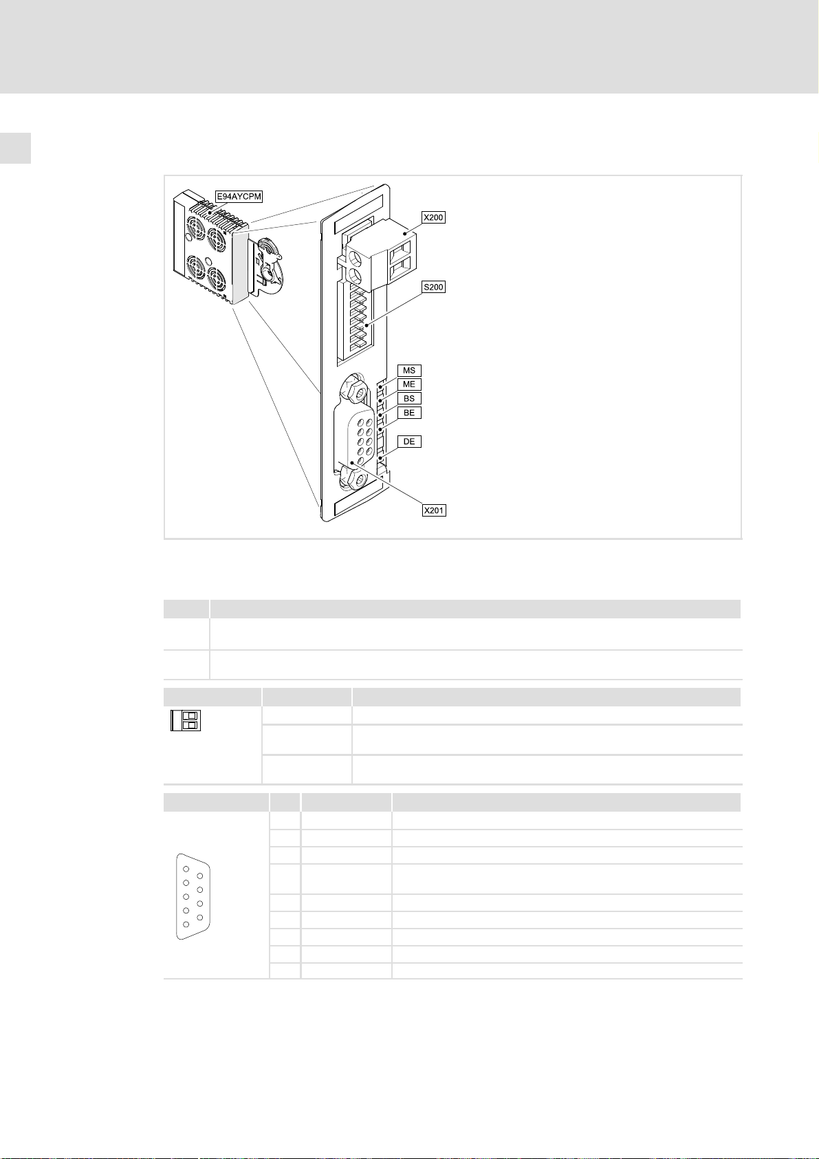
PROFIBUS
Abb. 8−4 Kommunikationsmodul E94AYCPM (PROFIBUS)
Anschlüsse
Pos. Beschreibung
X200 Externe Versorgung des Kommunikationsmoduls
Ausführung: Steckerleiste mit Schraubanschluss, 2−polig
X201 Anschluss für PROFIBUS
Ausführung: Sub−D−Buchse, 9−polig
X200 Beschriftung Beschreibung
+
-
+ 24VDC
− GND
SSP94KP200
Ansicht Pin Bezeichnung Erläuterung
1 frei −
2 frei −
3 RxD/TxD−P Datenleitung−B (Empfangsdaten−/Sendedaten−Plus)
1
2
3
4
5
6
7
8
9
4 RTS Request To Send (Empfangsdaten/Sendedaten, kein Differenzsi-
5 M5V2 Datenbezugspotenzial (Masse zu 5V)
6 P5V2 5 V DC / 30 mA (Busabschluss)
7 frei −
8 RxD/TxD−N Datenleitung−A (Empfangsdaten−/Sendedaten−Minus)
9 frei −
24 V externe Versorgung durch ein sicher getrenntes Netzteil (SELV/PELV)
20,4 − 0% ... 28,8 V+ 0%, max. 200 mA
Bezugspotential
gnal)
E94YCPM001A
30
EDK94AMH24 DE/EN/FR/ES/IT 3.1
Page 31

Gerätemodule verdrahten
Kommunikationsmodule
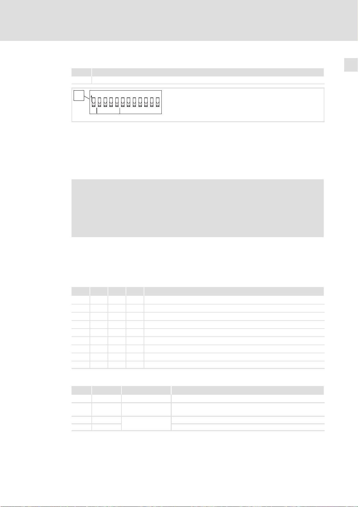
DIP−Schalter
Pos. Beschreibung
A Adressierung des Teilnehmers
Zur Adressierung wird für jeden Teilnehmer eine eindeutige Adresse vergeben.
Gültiger Adressbereich: 1 … 126
Die Einstellung der Adresse ist über den frontseitigen Schalter frei wählbar.
Hinweis!
ƒ Wenn S1 − S7 = OFF (Lenze−Einstellung):
Beim Einschalten wird die Konfiguration aus der Codestelle C00899 aktiv.
ƒ Sobald ein Schalter S1 − S7 = ON:
Beim Einschalten wird die Adresse aus der Schalterstellung aktiv.
Schalten Sie die Spannungsversorgung des Kommunikationsmoduls aus und
anschließend wieder ein, um geänderte Einstellungen zu aktivieren.
8
Adresseinstellungen durch den DIP−Schalter (Gerätefront)
Die Summe der Wertigkeiten (identisch mit Gehäuse−Beschriftung) ergibt die einzustellende Teilnehmeradresse.
Beispiel:
Schalter S7 S6 S5 S4 S3 S2 S1
Gehäuse−Beschriftung «64» «32» «16» «8» «4» «2» «1»
Schalterzustand 0 0 1 0 1 1 1
Adresse (= 23) 0 0 16 0 4 2 1
Anzeigen
LED
Pos. Farbe Zustand
MS grün
ME rot an Ein Fehler liegt im Bereich des Kommunikationsmoduls vor.
BS grün blinkt Die Kommunikation über das Kommunikationsmodul ist aufgebaut. Die
BE rot an Die Busüberwachung hat angesprochen.
DE rot an Das Kommunikationsmodul wird vom Grundgerät nicht akzeptiert.
an Das Kommunikationsmodul ist mit Spannung versorgt und hat eine Ver-
blinkt Das Kommunikationsmodul ist mit Spannung versorgt, hat aber keine
Beschreibung
bindung zum Grundgerät.
Verbindung zum Grundgerät. (Das Grundgerät ist ausgeschaltet, in der Initialisierungsphase oder nicht vorhanden.)
PROFIBUS−Kommunikation ist aktiv.
(Siehe Hinweise in der Dokumentation zum Grundgerät.)
EDK94AMH24 DE/EN/FR/ES/IT 3.1
31
Page 32

8
Gerätemodule verdrahten
Funktionsmodule
8.2 Funktionsmodule
Diese Module in Schacht þ MXI1 oder þ MXI2 o MMI o MSI verwenden.
Leitfrequenz
Anschlüsse
Pos. Beschreibung
X9 Eingang Leitfrequenz, 9−poliger Sub−D−Stecker
X10 Ausgang Leitfrequenz, 9−polige Sub−D−Buchse
X9 Pin Bezeichnung Erläuterung
5
1
9
6
SUBD09010
1 B
2 A
3 A
4 +5 V geregelte Spannungsversorgung für Encoder
5 GND −
6 Z
7 Z
8
l S
l Lc
l E
9 B TTL−Eingangssignal vom Encoder oder Encodernachbildung
TTL−Eingangssignal vom Encoder oder Encodernachbildung
(Pin 8 = Sense muss verwendet werden, max. Regelbereich 5 ... 9 V)
TTL−Eingangssignal vom Encoder oder Encodernachbildung
Die Funktion dieser Leitung muss im Grundgerät eingestellt werden:
l Sense (Fühlerleitung bei Spannungsregelung, Lenze−Einstellung)
l Lamp control
l Enable
E94AYFLF004
32
EDK94AMH24 DE/EN/FR/ES/IT 3.1
Page 33

Gerätemodule verdrahten
Funktionsmodule
X10 Pin Bezeichnung Erläuterung
16
59
SUBD09010
Anzeigen
Pos. Farbe Zustand Beschreibung
MS grün leuchtet Das Modul ist mit Spannung versorgt.
DE rot leuchtet
1 B
2 A
3 A
4 +5 V VCC ±6 %
5 GND −
6 Z
7 Z
8 Enable Digitales Ausgangssignal
9 B TTL−Ausgangssignal vom Encoder oder Encodernachbildung
TTL−Ausgangssignal vom Encoder oder Encodernachbildung
TTL−Ausgangssignal vom Encoder oder Encodernachbildung
Das Modul wird vom Grundgerät nicht akzeptiert (siehe Hinweise
in der Anleitung zum Grundgerät).
8
EDK94AMH24 DE/EN/FR/ES/IT 3.1
33
Page 34

8
Gerätemodule verdrahten
Speichermodule
8.3 Speichermodule
Diese Module in Schacht o MXI1 o MXI2 þ MMI o MSI verwenden.
MM1xx
Ausstattung MM1xx
ƒ 1 MB Flash−Speicher
Abb. 8−5 Speichermodul E94AYM1x
Position Beschriftung Beschreibung
− − Es sind keine externen Elemente vorhanden.
MM2xx / MM3xx / MM4xx
Ausstattung MM2xx:
ƒ 1 MB Flash−Speicher
ƒ Systembus−Adressschalter (CAN)
Ausstattung MM3xx:
ƒ 4 MB Flash−Speicher
ƒ Systembus−Adressschalter (CAN)
Ausstattung MM4xx:
ƒ 8 MB Flash−Speicher
ƒ 128 kB RAM (batteriegepuffert)
ƒ Echtzeituhr
ƒ Systembus−Adressschalter (CAN)
SSP94M0001
34
EDK94AMH24 DE/EN/FR/ES/IT 3.1
Page 35

Gerätemodule verdrahten
Speichermodule
Abb. 8−6 Speichermodul mit DIP−Schalter (ab Bestellbezeichnung E94AYM22)
O
N
A
643216 8
cdba
421
8
SSP94M1001
Baud
Abb. 8−7 Anordnung und Beschriftung der DIP−Schalter
CAN Address
9400CAN003
Bei den frontseitig angeordneten DIP−Schaltern können
ƒ Knotenadresse (Beschriftung "1" ... "64") und
ƒ Übertragungsrate (Beschriftung "a" ... "d")
eingestellt werden.
Hinweis!
Wenn beim beim Einschalten des Grundgerätes alle Adressschalter die
Stellung "OFF" einnehmen, erfolgt die Übernahme aus den Konfigurationen
der Codestellen C00350 (Knotenadresse) und C00351 (Übertragungsrate).
Schalten Sie die Spannungsversorgung des Grundgerätes aus und
anschließend wieder ein, um geänderte Einstellungen zu aktivieren.
Einstellen der Knotenadresse
Die Knotenadresse des Antriebs errechnet sich aus der Summe aller in Stellung "ON" positionierten Adressschalter.
EDK94AMH24 DE/EN/FR/ES/IT 3.1
35
Page 36

8
Gerätemodule verdrahten
Speichermodule
Einstellen der Übertragungsrate
d c b a Übertragungsrate
OFF ON ON OFF 10 kBit/s
OFF ON OFF ON 20 kBit/s
OFF OFF ON ON 50 kBit/s
OFF OFF ON OFF 125 kBit/s
OFF OFF OFF ON 250 kBit/s
OFF OFF OFF OFF 500 kBit/s
ON ON ON OFF 800 kBit/s
OFF ON OFF OFF 1000 kBit/s
OFF ON ON ON Autobaud
36
EDK94AMH24 DE/EN/FR/ES/IT 3.1
Page 37

8.4 Sicherheitsmodule
Gefahr!
Bei Einsatz von Sicherheitsmodulen müssen Hinweise und die Beschreibung
zum Modultyp unbedingt beachtet werden. Es sind wichtige Informationen
enthalten, damit die Funktionen im Anforderungsfall "sicher" ausgeführt
werden.
Missachtung der Informationen gefährdet Mensch und Maschine!
Diese Module in Schacht o MXI1 o MXI2 o MMI þ MSI verwenden.
SM0
Funktion
ƒ Es sind keine Sicherheitsfunktionen verfügbar.
ƒ Dieses Modul ist für den Betrieb des Antriebsreglers ohne Sicherheitsfunktionen
erforderlich.
Gerätemodule verdrahten
Sicherheitsmodule
8
Hinweis!
Sind Sicherheitsfunktionen erforderlich, ersetzen Sie dieses Modul durch ein
Modul mit Sicherheitsfunktionen (z. B. SM100, SM301).
Abb. 8−8 Sicherheitsmodul E94AYAA
Pos. Beschriftung Beschreibung
− − Das Modul hat keine Elemente auf der Frontseite.
SSP94SM011
EDK94AMH24 DE/EN/FR/ES/IT 3.1
37
Page 38

8
Gerätemodule verdrahten
Sicherheitsmodule
SM100
Funktion
ƒ Sicher abgeschaltetes Moment
(bisher: Sicherer Halt, Schutz gegen unerwarteten Anlauf)
Abb. 8−9 Sicherheitsmodul E94AYAB
Anschlüsse
Pos. Beschriftung Beschreibung
X80 SI1 Eingang erster Abschaltpfad
GI GND−Potential für SI1/SI2
SI2 Eingang zweiter Abschaltpfad
GO GND−Potential Rückmeldung
24O 24−V−Spannungsversorgung Rückmeldung
DO1 Nichtsicherer Meldeausgang Sichere Impulssperre"
Klemmendaten
Leiterquerschnitt Anzugsmoment
[mm2] [AWG] [Nm] [lb−in]
starr 0.2 ... 2.5 24 ... 12
Aderendhülse,
isoliert
Doppel−Aderend-
hülse
0.2 ... 1.5 24 ... 16
0.5 ... 1.0 20 ... 18
Anzeigen
Pos. Farbe Zustand Beschreibung
EN gelb
DE rot an
an Antriebsregler freigegeben
aus Nichtsichere Anzeige "Sichere Impulssperre"
Das Modul wird vom Grundgerät nicht akzeptiert (siehe Hinweise
in der Anleitung zum Grundgerät).
SSP94SM112
Federkraftklemme
38
EDK94AMH24 DE/EN/FR/ES/IT 3.1
Page 39

Gerätemodule verdrahten
Sicherheitsmodule
SM301
Funktionen
ƒ Sicher abgeschaltetes Moment (STO)
(bisher: Sicherer Halt, Schutz gegen unerwarteten Anlauf)
ƒ Sicherer Stopp 1 (SS1)
ƒ Sicherer Stopp 2 (SS2) − in Anlehnung an IEC 61800−5−2: siehe SOS
ƒ Not−Stopp (SSE)
ƒ Sicherer Betriebshalt (SOS) − in Anlehnung an IEC 61800−5−2: SOS ist
drehzahlüberwacht ausgeführt
ƒ Sichere maximale Geschwindigkeit (SMS)
ƒ Sicher begrenzte Geschwindigkeit 1 (SLS1)
ƒ Sicherer Betriebsartenwahlschalter (OMS)
8
ƒ Sicherer Zustimmtaster (ES)
ƒ Sichere Rückmeldung begrenzte Geschwindigkeit (SSM)
ƒ Sichere Rückmeldung (Ausgang)
ƒ Anschluss von Sicherheitssensoren
ƒ Sichere Parametrierung
ƒ Sicherheitsbus Anbindung (PROFIsafe V1)
zusätzliche Funktionen ab SM301 V1.1
ƒ Sicher begrenzte Geschwindigkeit 2 (SLS2)
ƒ Sicher begrenzte Geschwindigkeit 3 (SLS3)
ƒ Sicher begrenzte Geschwindigkeit 4 (SLS4)
ƒ Sichere Kaskadierung (CAS) über SD−In4/SD−Out1
ƒ Sicherheitsbus Anbindung (PROFIsafe V2)
EDK94AMH24 DE/EN/FR/ES/IT 3.1
39
Page 40

8
Gerätemodule verdrahten
Sicherheitsmodule
SSP94SM321
Anschlüsse
Pos. Beschreibung
Safety−Adressschalter (in der linken Gehäuseseite)
S82 Modultaster zur Parametersatzübernahme vom Speichermodul
X82.1
X82.2
X82.3
X82.4
Steckbare Klemmleisten für Eingangssignale und Ausgangssignale
40
EDK94AMH24 DE/EN/FR/ES/IT 3.1
Page 41

Gerätemodule verdrahten
Sicherheitsmodule
Adressierung
Die Safety−Adresse dient der eindeutigen Zuordnung der Sicherheitsmodule des Typs
SM301 in Anlagen mit mehreren Antrieben. Die Adresse "0" ist nicht zulässig.
Adress−Schalter
Die Safety−Adresse kann mit dem DIP−Schalter in der linken Gehäuseseite eingestellt
werden. Verwenden Sie zum Einstellen des Schalters ein angemessen kleines Hilfsmittel,
z. B. eine Prüfspitze. Der Schalter kann nur eingestellt werden, wenn das Modul nicht in einem Grundgerät steckt. Mit dem Schalter können Adressen im Bereich 0 ... 1023 eingestellt werden. Änderungen der Adresse durch den Schalter werden erst mit dem Einschalten der 24−V−Versorgung aktiviert. Die Adresseinstellung "0" erfordert die Einstellung
durch die Adress−Codestelle.
DIP−Schalter Beschriftung
1 2 3 4 5 6 7 8 9 0
Wertigkeit des Adressbits 1 2 4 8 16 32 64 128 256 512
8
Hinweis!
Im Sicherheitsmodul SM301 ab Version VA 1.xx wird die Adresse 0 wie folgt
ersetzt:
ƒ Mit der im Sicherheitsmodul im Parameter "Safety Adresse" (C15111)
gespeicherten Adresse.
ƒ Kann die Adresse 0 nicht ersetzt werden, meldet das Modul einen Fehler.
EDK94AMH24 DE/EN/FR/ES/IT 3.1
41
Page 42

8
Gerätemodule verdrahten
Sicherheitsmodule
Klemmenbelegung
Hinweis!
Sorgen Sie für ausreichende Zugentlastung, damit die Klemmen nicht aus den
Stiftleisten gezogen werden, insbesondere wenn Sie starre Leitungen
verwenden.
X82.1 Beschriftung Beschreibung
Dieser Teil der Klemmleiste ist nicht belegt.
GO GND SD−Out1
O1B Sichere Rückmeldung SD−Out1, Kanal B
O1A Sichere Rückmeldung SD−Out1, Kanal A
Dieser Teil der Klemmleiste ist nicht belegt.
X82.2 Beschriftung Beschreibung
− GND externe Versorgung
+ +24 V externe Versorgung durch ein sicher getrenntes Netzteil (SELV/PELV)
GIR
RI1
GO GND 24O
24O +24 V externe Versorgung für die sichere Rückmeldung SD−Out1 (SELV/
AIE Fehlerquittierungseingang ("Acknowledge In Error")
CLA Taktausgang für passive Sensoren, Kanal A (Clock A)
CLB Taktausgang für passive Sensoren, Kanal B (Clock B)
X82.3 Beschriftung Beschreibung
GCL GND Taktausgang
GI2 GND SD−In2
I2B Sensoreingang SD−In2, Kanal B
I2A Sensoreingang SD−In2, Kanal A
GCL GND Taktausgang
GI1 GND SD−In1
I1B Sensoreingang SD−In1, Kanal B
I1A Sensoreingang SD−In1, Kanal A
AIS Wiederanlaufquittierungseingang ("Acknowledge In Stop", 1−kanalig, ge-
Dieser Teil der Klemmleiste ist reserviert.
PELV)
brückt zu X82.4/AIS)
42
EDK94AMH24 DE/EN/FR/ES/IT 3.1
Page 43

Gerätemodule verdrahten
Sicherheitsmodule
X82.4 Beschriftung Beschreibung
GCL GND Taktausgang
GI4 GND SD−In4
I4B Sensoreingang SD−In4, Kanal B
I4A Sensoreingang SD−In4, Kanal A
GCL GND Taktausgang
GI3 GND SD−In3
I3B Sensoreingang SD−In3, Kanal B
I3A Sensoreingang SD−In3, Kanal A
AIS Wiederanlaufquittierungseingang ("Acknowledge In Stop", 1−kanalig, ge-
Leitungsquerschnitte und Anzugsmomente
Art [mm2] [Nm] AWG [lb−in]
Aderendhülse isoliert 0,25 ... 0,75
starr 0,14 ... 1,5 26 ... 16
Abisolierlänge bzw. Kontaktlänge: 9 mm
brückt zu X82.3/AIS)
Federkraftklemme
24 ... 18
Federkraftklemme
8
Anzeigen
Pos. Farbe Zustand Beschreibung
an Integrierte Sicherheitstechnik ist fehlerfrei initialisiert.
blinkt
MS
(Module State)
EN
(Enable)
ME
(Module Error)
AS
(Acknowledge Stop)
BE
(Bus Error)
DE
(Drive Error)
Blinken: an/aus im 0,5−s−Takt Blitzen: an/aus im 0,1/0,9−s−Takt
grün
gelb
rot
gelb
rot
rot
blitzt
aus
an Regler freigegeben
aus Nicht sichere Anzeige "STO"
an Systemfehler
blinkt Störung
blitzt Warnung
aus Fehlerfreier Betrieb
an
blinkt SS1/STO aktiv
blitzt SS2/SOS aktiv
aus Keine Stopp−Funktion aktiv
an
blinkt Fehler Sicherheitsbus: Keine gültige Konfiguration.
aus Sicherheitsbus: Fehlerfreier Betrieb.
an
aus
Integrierte Sicherheitstechnik ist fehlerfrei initialisiert. Die
interne Kommunikation zum Grundgerät ist nicht möglich.
Integrierte Sicherheitstechnik ist im Service−Zustand.
Zum Verlassen die integrierte Sicherheitstechnik parametrieren.
Integrierte Sicherheitstechnik ist nicht initialisiert.
Es ist keine Quittierung möglich.
Anforderung einer Quittierung für den Wiederanlauf oder
die Parametersatzübernahme
Fehler Sicherheitsbus:
l Die Kommunikation ist nicht möglich.
l Quittierung ist möglich.
Integrierte Sicherheitstechnik wird vom Grundgerät nicht
akzeptiert (siehe Hinweise in der Anleitung zum Grundgerät).
Integrierte Sicherheitstechnik vom Grundgerät ordnungsgemäß erkannt.
EDK94AMH24 DE/EN/FR/ES/IT 3.1
43
Page 44

9
Abschließende Arbeiten
Inbetriebnahme vorbereiten
9 Abschließende Arbeiten
9.1 Inbetriebnahme vorbereiten
Für die Inbetriebnahme benötigen Sie:
ƒ Einen Computer mit Windows®−Betriebssystem (XP oder 2000)
ƒ Die Lenze PC−Software »Engineer«
ƒ Eine Verbindung mit dem Antriebsregler über eine Schnittstelle, z. B.
– Diagnoseschnittstelle X6 mit USB−Diagnoseadapter
– Systembus CAN
– Kommunikationsmodule in den Erweiterungssteckplätzen MXI1/MXI2
ƒ Das Softwarehandbuch für die verwendete Technologieapplikation
ƒ Das Kommunikationshandbuch (KHB) zum Netzwerk der
Automatisierungsplattform
ƒ 24−V−Spannungsversorgung für die Steuerelektronik des Antriebsreglers
ƒ DC−Zwischenkreisspannung
Folgen Sie den Anleitungen der Software und/oder lesen Sie die Dokumentation.
44
EDK94AMH24 DE/EN/FR/ES/IT 3.1
Page 45

Abschließende Arbeiten
Inbetriebnahme vorbereiten
9
EDK94AMH24 DE/EN/FR/ES/IT 3.1
45
Page 46

Overview
Standard device Design
Pos. Description HighLine StateLine
MXI1 Module receptacle for extension 1, e.g. communication þ þ
MXI2 Module receptacle for extension 2, e.g. communication þ o
MMI Module receptacle for memory modules þ þ
MSI Module receptacle for safety modules þ þ
X1 System bus (CAN), under the cover þ o
X2 24−V supply and state bus þ þ
X3 Analog inputs and analog outputs 2/2 1/0
X4 Digital outputs 4 1
X5 Digital inputs 8 4
X6 Diagnostics þ þ
X7 Resolver þ þ
X8 Encoder þ þ
Lower cap þ þ
Nameplate, retractable þ þ
Upper cap þ þ
EMC clamp 1 1
Warning sticker − place close to the device in a clearly visible manner! þ þ
The LED display enables fast indication of several operating states.
LED Labelling Colour Description
CAN−RUN green CAN bus o.k.
CAN−ERR red CAN bus error
DRIVE READY green Standard device is ready for operation
DRIVE ERROR red Error in the standard device or due to the application
24 V green 24−V supply voltage o.k.
SSP94LED01
Pos. Symbol Description
Installation backplane Design
Pos. Description HighLine StateLine
X100 DC−bus voltage (compatible to 9300 series) þ
X105 Motor þ
X106 Motor temperature monitoring þ
X107 Control of motor holding brake Optional
X109 DC busbar +
X110 DC busbar −
EMC wire clamp (for device sizes 2 + 3), replaces 1x 1
EMC shield clamp 3 or 2
DC−bus fuse þ
USER yellow Message parameterised by the application
0Fig. 0Tab. 0
Long discharge time: All power terminals carry hazardous voltages for at
least 3 minutes after mains disconnection!
High discharge current: Fixed installation and PE connection to EN 61800−5−1
required!
Electrostatic sensitive devices: Before working on the device, personnel must
ensure that they are free of electrostatic charge!
Inoperable when "StateLine" design is
used
þ
46
EDK94AMH24 DE/EN/FR/ES/IT 3.1
Page 47

Contents i
1 Quick start guide 48. . . . . . . . . . . . . . . . . . . . . . . . . . . . . . . . . . . . . . . . . . . . . . . . . . . . . . . . . .
2 Safety instructions 49. . . . . . . . . . . . . . . . . . . . . . . . . . . . . . . . . . . . . . . . . . . . . . . . . . . . . . . . .
2.1 General safety and application notes for Lenze controllers 49. . . . . . . . . . . . . . . . . .
2.2 Residual hazards 52. . . . . . . . . . . . . . . . . . . . . . . . . . . . . . . . . . . . . . . . . . . . . . . . . . . . .
2.3 Notes used 53. . . . . . . . . . . . . . . . . . . . . . . . . . . . . . . . . . . . . . . . . . . . . . . . . . . . . . . . . .
2.4 Safety instructions for the installation according to UL oder UR 54. . . . . . . . . . . . . .
3 Technical data 55. . . . . . . . . . . . . . . . . . . . . . . . . . . . . . . . . . . . . . . . . . . . . . . . . . . . . . . . . . . .
3.1 General data and operating conditions 55. . . . . . . . . . . . . . . . . . . . . . . . . . . . . . . . .
3.2 Electrical data 57. . . . . . . . . . . . . . . . . . . . . . . . . . . . . . . . . . . . . . . . . . . . . . . . . . . . . . . .
3.3 Dimensions 59. . . . . . . . . . . . . . . . . . . . . . . . . . . . . . . . . . . . . . . . . . . . . . . . . . . . . . . . . .
4 Example circuit 60. . . . . . . . . . . . . . . . . . . . . . . . . . . . . . . . . . . . . . . . . . . . . . . . . . . . . . . . . . . .
5 Mounting and wiring the installation backplane 61. . . . . . . . . . . . . . . . . . . . . . . . . . . . . . . .
6 Mounting the standard device 62. . . . . . . . . . . . . . . . . . . . . . . . . . . . . . . . . . . . . . . . . . . . . . .
7 Wiring of the standard device 63. . . . . . . . . . . . . . . . . . . . . . . . . . . . . . . . . . . . . . . . . . . . . . .
8 Wiring the device modules 69. . . . . . . . . . . . . . . . . . . . . . . . . . . . . . . . . . . . . . . . . . . . . . . . . .
8.1 Communication modules 69. . . . . . . . . . . . . . . . . . . . . . . . . . . . . . . . . . . . . . . . . . . . . .
8.2 Function modules 74. . . . . . . . . . . . . . . . . . . . . . . . . . . . . . . . . . . . . . . . . . . . . . . . . . . .
8.3 Memory modules 76. . . . . . . . . . . . . . . . . . . . . . . . . . . . . . . . . . . . . . . . . . . . . . . . . . . . .
8.4 Safety modules 79. . . . . . . . . . . . . . . . . . . . . . . . . . . . . . . . . . . . . . . . . . . . . . . . . . . . . .
9 Final works 86. . . . . . . . . . . . . . . . . . . . . . . . . . . . . . . . . . . . . . . . . . . . . . . . . . . . . . . . . . . . . . .
9.1 Preparing the commissioning procedure 86. . . . . . . . . . . . . . . . . . . . . . . . . . . . . . . . .
EDK94AMH24 DE/EN/FR/ES/IT 3.1
47
Page 48

Quick start guide1
1 Quick start guide
How to proceed for the installation:
1. Read the safety instructions à from page 49
2. Inform yourself about the technical data à from page 55
3. Mount the installation backplane into
the control cabinet and wire it
4. Insert the standard device into the
installation backplane
5. Wire the standard device à from page 63
6. Adjust and wire the device modules
– Wire the communication modules.
– Adjust the memory modules.
– Wire the safety modules.
7. Final works à from page 86
à from page 61
à from page 62
à from page 69
48
Tip!
Documentation and software updates for further Lenze products can be found
on the Internet in the "Services & Downloads" area under
http://www.Lenze.com
EDK94AMH24 DE/EN/FR/ES/IT 3.1
Page 49

Safety instructions
General safety and application notes for Lenze controllers
2 Safety instructions
2.1 General safety and application notes for Lenze controllers
(in accordance with Low−Voltage Directive 2006/95/EC)
General
Lenze controllers (frequency inverters, servo inverters, DC controllers) and the accessory
components can include live and rotating parts − depending on their type of protection −
during operation. Surfaces can be hot.
Non−authorised removal of the required cover, inappropriate use, incorrect installation or
operation, create the risk of severe injury to persons or damage to material assets.
More information can be obtained from the documentation.
All operations concerning transport, installation, and commissioning as well as
maintenance must be carried out by qualified, skilled personnel (IEC 364/CENELEC HD 384
or DIN VDE 0100 and IEC report 664 or DIN VDE 0110 and national regulations for the
prevention of accidents must be observed).
2
According to this basic safety information qualified, skilled personnel are persons who are
familiar with the assembly, installation, commissioning, and operation of the product and
who have the qualifications necessary for their occupation.
Application as directed
Drive controllers are components which are designed for installation in electrical systems
or machinery. They are not to be used as domestic appliances, but only for industrial
purposes according to EN 61000−3−2.
When installing the controllers into machines, commissioning (i.e. starting of operation as
directed) is prohibited until it is proven that the machine corresponds to the regulations
of the EC Directive 98/37/EC (Machinery Directive); EN 60204 must be observed.
Commissioning (i.e. starting of operation as directed) is only allowed when there is
compliance with the EMC Directive (2004/108/EC).
The drive controllers meet the requirements of the Low−Voltage Directive 2006/95/EC. The
harmonised standard EN 61800−5−1 applies to the drive controllers.
The technical data and information on connection conditions can be obtained from the
nameplate and the documentation. They must be strictly observed.
Warning: The drive controllers are products which are intended for use in an industrial
environment according to EN 61800−3. Operation on public mains supplies requires
additional measures to be taken for limiting the expected radio interference.
Transport and storage
Please observe the notes on transport, storage and appropriate handling.
Observe the climatic conditions according to the technical data.
EDK94AMH24 DE/EN/FR/ES/IT 3.1
49
Page 50

2
Safety instructions
General safety and application notes for Lenze controllers
Installation
The controllers must be installed and cooled according to the instructions given in the
corresponding documentation.
Ensure proper handling and avoid mechanical stress. Do not bend any components and do
not change any insulation distances during transport or handling. Do not touch any
electronic components and contacts.
Controllers contain electrostatically sensitive components, which can easily be damaged
by inappropriate handling. Do not damage or destroy any electrical components since this
might endanger your health!
Electrical connection
When working on live controllers, the valid national regulations for the prevention of
accidents (e.g. VBG 4) must be observed.
The electrical installation must be carried out according to the appropriate regulations
(e.g. cable cross−sections, fuses, PE connection). Additional information can be obtained
from the documentation.
Notes about installation according to EMC regulations (shielding, earthing, filters and
cable routing) are included in the documentation. These notes also apply to CE−marked
controllers. The compliance with limit values required by the EMC legislation is the
responsibility of the manufacturer of the machine or system. The controllers must be
installed in housings (e.g. control cabinets) to meet the limit values for radio interferences
valid at the site of installation. The housings must enable an EMC−compliant installation.
Observe in particular that e.g. the control cabinet doors should have a circumferential
metal connection to the housing. Reduce housing openings and cutouts to a minimum.
Lenze controllers can cause a direct current in the protective conductor. If a residual current
device (RCD) is used as a protective means in the case of direct or indirect contact, only a
residual current device (RCD) of type B may be used on the current supply side of the
controller. Otherwise, another protective measure such as separation from the
environment through double or reinforced insulation or disconnection from the mains by
means of a transformer must be used.
Operation
If necessary, systems including controllers must be equipped with additional monitoring
and protection devices according to the valid safety regulations (e.g. law on technical
equipment, regulations for the prevention of accidents). The controller can be adapted to
your application. Please observe the corresponding information given in the
documentation.
After a controller has been disconnected from the voltage supply, all live components and
power connections must not be touched immediately because capacitors can still be
charged. Please observe the corresponding stickers on the controller.
50
All protection covers and doors must be shut during operation.
Note for UL approved systems with integrated controllers: UL warnings are notes that only
apply to UL systems. The documentation contains special UL notes.
EDK94AMH24 DE/EN/FR/ES/IT 3.1
Page 51

Safety instructions
General safety and application notes for Lenze controllers
Safety functions
Special controller variants support safety functions (e.g. "safe torque off", previously "safe
standstill") according to the requirements of Annex I No. 1.2.7 of the EC Directive
"Machinery" 98/37/EC, IEC 61508, EN 954−1 and EN 1037. Strictly observe the notes on the
safety functions given in the documentation for the respective variants.
Maintenance and servicing
The controllers do not require any maintenance if the prescribed conditions of operation
are observed.
If the ambient air is polluted, the cooling surfaces of the controller may become dirty or the
air vents of the controller may be obstructed. Therefore, clean the cooling surfaces and air
vents periodically under these operating conditions. Do not use sharp or pointed tools for
this purpose!
Disposal
Recycle metal and plastic materials. Ensure professional disposal of assembled PCBs.
2
The product−specific safety and application notes given in these instructions must be
observed!
EDK94AMH24 DE/EN/FR/ES/IT 3.1
51
Page 52

2
Safety instructions
Residual hazards
2.2 Residual hazards
Protection of persons
ƒ Before starting work on the controller, check that the power terminals are
deenergised
– because the power terminals U, V, W, +UG and −UG carry hazardous voltages for at
least 3 minutes after mains disconnection.
– because the power terminals U, V, W, +UG and −UG carry hazardous voltages when
the motor is stopped.
Device protection
ƒ Plug on or pull off all pluggable terminals only in deenergised condition!
ƒ Detach the controllers only in deenergised conditions from their installation
backplanes or the back panel of the control cabinet!
ƒ Cyclic switching on and off of the mains voltage can overload and destroy the input
current limitation of the controller:
– Cyclic mains switching of 5−times in 5 minutes is permissible without restrictions.
Motor protection
ƒ Depending on the controller settings, the connected motor can be overheated by:
– For instance, longer DC−braking operations.
– Longer operation of self−ventilated motors at low speed.
Protection of the machine/system
ƒ Drives can reach dangerous overspeeds (e.g. setting of high output frequencies in
connection with motors and machines unsuitable for such conditions):
– The controllers do not offer any protection against such operating conditions. Use
additional components for this purpose.
52
EDK94AMH24 DE/EN/FR/ES/IT 3.1
Page 53

Safety instructions
Notes used
2
2.3 Notes used
The following pictographs and signal words are used in this documentation to indicate
dangers and important information:
Safety instructions
Structure of safety instructions:
Danger!
(characterises the type and severity of danger)
Note
(describes the danger and gives information about how to prevent dangerous
situations)
Pictograph and signal word Meaning
Danger!
Danger!
Stop!
Danger of personal injury through dangerous electrical voltage.
Reference to an imminent danger that may result in death or
serious personal injury if the corresponding measures are not
taken.
Danger of personal injury through a general source of danger.
Reference to an imminent danger that may result in death or
serious personal injury if the corresponding measures are not
taken.
Danger of property damage.
Reference to a possible danger that may result in property
damage if the corresponding measures are not taken.
Application notes
Pictograph and signal word Meaning
Note!
Tip!
Special safety instructions and application notes for UL and UR
Pictograph and signal word Meaning
Warnings!
Warnings!
Important note to ensure troublefree operation
Useful tip for simple handling
Reference to another documentation
Safety or application note for the operation of a UL−approved
device in UL−approved systems.
Possibly the drive system is not operated in compliance with UL
if the corresponding measures are not taken.
Safety or application note for the operation of a UR−approved
device in UL−approved systems.
Possibly the drive system is not operated in compliance with UL
if the corresponding measures are not taken.
EDK94AMH24 DE/EN/FR/ES/IT 3.1
53
Page 54

2
Safety instructions
Safety instructions for the installation according to UL oder UR
2.4 Safety instructions for the installation according to UL oder U
Warnings!
ƒ The integral solid state protection does not provide branch circuit protection
and that branch circuit protection has to be provided externally in
accordance with manufacturers instructions, the National Electrical Code
and any additional codes.
ƒ For information on the protection level of the internal overload protection
for a motor load, see the corresponding Application Manuals or Software
Helps.
ƒ For information on rating and proper connection of the thermal protector
(only for connection to motors having integral thermal protection), see the
corresponding Application Manuals or Software Helps.
ƒ Maximum surrounding air temperature: 55 °C.
ƒ Use 60/75 °C copper wire only, except for control circuits.
ƒ Control card protection:
External fuse for 24 Vdc supply voltage of control terminal X2. Rated 4 A DC
fuse UL248−14.
R
54
EDK94AMH24 DE/EN/FR/ES/IT 3.1
Page 55

General data and operating conditions
3 Technical data
3.1 General data and operating conditions
Supply system data
Supply forms
Noise emission EN 61800−3
Noise immunity EN 61800−3 Category C3
Conformity and approval
Conformity
CE
Approval
UL UL 508C Power Conversion Equipment, File No. 132659
GOST−R 51321.1−2000
With earthed neutral
IT systems Observe instructions about special measures!
2006/95/EC Low−voltage directive
51321.3−99
Technical data
Unrestricted use
Cable−guided: cannot be specified because dependent on the
conditions present in the interconnected system
Radiation: category C3
No. POCC DE.AN30.B08815
3
Protection of persons and devices
Enclosure
Insulation resistance EN 61800−5−1 Overvoltage category III
Insulation of control
circuits
Short−circuit strength EN 61800−5−1 Motor connection: with restrictions, error acknowledgement
Motor − protective
measures against
Discharge current EN 61800−5−1 > 3.5 mA AC, > 10 mA DC Observe regulations and
Cyclic mains switching Cyclic mains switching of 5 times in 5 minutes is permissible
EN 60529
NEMA 250 Protection against contact in
EN 61800−5−1 Safe mains isolation by double/reinforced insulation for
IP 20
accordance with type 1
Reduction from 2000 m amsl onwards: Overvoltage category
II
mains with neutral earthing with a rated voltage for the
external conductor/star point up to 300 V.
required
Control connections: without restrictions
l Short circuit
l Earth fault
l Overvoltage
l Motor stalling
l Motor overtemperature
(PTC or thermal contact, I
without restrictions.
Not in the wire range of
the terminals on the
motor side
2
t monitoring)
safety instructions!
EDK94AMH24 DE/EN/FR/ES/IT 3.1
55
Page 56

3
Technical data
General data and operating conditions
Environmental conditions
Climate
Storage
Transport IEC/EN 60721−3−2 2K3 (−25 ... +70 °C)
Operation IEC/EN 60721−3−3 3K3 (−10 ... +55 °C)
Site altitude 0 ... 4000 m amsl
Pollution IEC/EN 60664−1 Pollution degree 2
Vibration resistance (9.81 m/s
Transport
Operation
IEC/EN 60721−3−1 1K3 (−25 ... +60 °C)
Current derating at +45 ... +55 °C:
Device size 1 ... 7: 2.5 %/°C
Device size 8S ... 10: 1 %/°C
1000 ... 4000 m amsl: current derating of 5 %/1000 m
2
= 1 g)
IEC/EN 60721−3−2 2M2
EN 61800−2
Germanischer Lloyd 5 ... 13.2 Hz: amplitude ±1 mm
IEC/EN 60068−2−6
2 ... 9 Hz: amplitude 3.5 mm
10 ... 200 Hz: acceleration resistant up to 10 m/s
200 ... 500 Hz: acceleration resistant up to 15 m/s
13.2 ... 100 Hz: acceleration resistant up to 0.7 g
10 ... 57 Hz: amplitude 0.075 mm
57 ... 150 Hz: acceleration resistant up to 10 m/s
2
2
2
Mounting conditions
Mounting place
Mounting position Vertical
Mounting clearances
Above/below ³ 80 mm / ³ 120 mm
To the sides Side−by−side mounting without
In the control cabinet
any clearance
Observe the device−related
notes on mounting.
56
EDK94AMH24 DE/EN/FR/ES/IT 3.1
Page 57

Technical data
Electrical data
3
3.2 Electrical data
Input data
Basis of the data
Mains Voltage
2/PE DC 325 260 − 0 % ... 370 + 0 % −
2/PE DC 565 455 − 0 % ... 620 + 0 % −
2/PE DC 705 565 − 0 % ... 775 + 0 % −
E94AMxE0024 325/565/705 0 ( DC) 2.6/2.6/2.3 2.0/2.0/1.7 2
E94AMxE0034 325/565/705 0 ( DC) 4.3/4.3/3.8 3.2/3.2/2.9 2
E94AMxE0044 325/565/705 0 ( DC) 6.7/6.7/5.9 5.0/5.0/4.4 2
E94AMxE0074 325/565/705 0 ( DC) 12.1/12.1/10.6 9.1/9.1/8.0 2
E94AMxE0094 325/565/705 0 ( DC) 15.4/15.4/13.5 11.6/11.6/10.1 2
E94AMxE0134 325/565/705 0 ( DC) 20.6/20.6/18.0 15.5/15.5/13.5 2
E94AMxE0174 325/565/705 0 ( DC) 25.7/25.7/22.5 19.3/19.3/16.9 2
E94AMxE0244 325/565/705 0 ( DC) 35.5/35.5/31.1 26.3/26.3/23.3 2
E94AMxE0324 325/565/705 0 ( DC) 48.0/48.0/38.9 36.0/36.0/29.1 2
Temperature in the control cabinet
Voltage range
UDC [V]
Voltage Frequency Current [A]
[V] [Hz] max. +45 °C max. +55 °C
UDC [V]
Frequency range
f [Hz]
Number of
phases
EDK94AMH24 DE/EN/FR/ES/IT 3.1
57
Page 58

3
Technical data
Electrical data
Output data
Voltage Frequency
Type [V] [Hz] max. +45 °C
E94AMxE0024 0 − 230/400/500 0 − 599 1.5/1.5/1.3 1.1/1.1/1.0 3
E94AMxE0034 0 − 230/400/500 0 − 599 2.5/2.5/2.2 1.9/1.9/1.7 3
E94AMxE0044 0 − 230/400/500 0 − 599 4/4/3.5 3/3/2.6 3
E94AMxE0074 0 − 230/400/500 0 − 599 7/7/6.1 5.3/5.3/4.6 3
E94AMxE0094 0 − 230/400/500 0 − 599 9.3/9.3/8.2 7.0/7.0/6.2 3
E94AMxE0134 0 − 230/400/500 0 − 599 13/13/11.4 9.8/9.8/8.6 3
E94AMxE0174 0 − 230/400/500 0 − 599 16.5/16.5/14.4 12.4/12.4/10.8 3
E94AMxE0244 0 − 230/400/500 0 − 599 23.5/23.5/20.6 17.6/17.6/15.5 3
E94AMxE0324 0 − 230/400/500 0 − 599 32.0/32.0/25.9 24.0/24.0/19.4 3
Temperature in the control cabinet
Type when operating with rated output current I
1)
Power loss PV [W]
aN
Current [A]
max. +55 °C
when controller is inhibited
Number of
phases
E94AMxE0024 65 80 95
E94AMxE0034 75 95 110
E94AMxE0044 90 120 130
E94AMxE0074 105 145 170
E94AMxE0094 130 170 205
E94AMxE0134 160 215 255
E94AMxE0174 185 255 300
E94AMxE0244 235 320 385
E94AMxE0324 290 405 490
Assignment of installation backplane ˘ standard device
Axis controller
type
E94AMxE0024
E94AMxE0034
E94AMxE0044
E94AMxE0074
E94AMxE0094
E94AMxE0134
E94AMxE0174
E94AMxE0244
E94AMxE0324 E94AZPM0324
Installation backplane type Fuse Device size
E94AZPM0044
E94AZPM0094 Siba 5020106.40A 2
E94AZPM0244
Siba 5020106.16A 1
Siba 2029221.100A
(tightening torque: 3.4 Nm
(30 lb−in))
Siba 2029221.100A
(tightening torque: 3.4 Nm
(30 lb−in))
40
3
3
58
EDK94AMH24 DE/EN/FR/ES/IT 3.1
Page 59

3.3 Dimensions
Standard device with installation backplane
Technical data
Dimensions
3
Fig. 3−1 Dimensions [mm]
Dimensions a Mass
Type [mm] [kg]
E94AMxE0024
E94AMxE0034
E94AMxE0044
E94AMxE0074
E94AMxE0094
E94AMxE0134
E94AMxE0174
E94AMxE0244
E94AMxE0324 120 8.5
60
90 5.3
120 8.1
SSP94GGmSo020
4.0
EDK94AMH24 DE/EN/FR/ES/IT 3.1
59
Page 60

Example circuit4
4 Example circuit
RFR
01
X109
X109
+UG
X110
X110
-UG
X106
T1
+
-
-UG
+UG
X100
RFR
GI
X5
E94AMxExxxx
X105 X107
T2
U
V
M
3~
J
+
E94AZPxxxxx
W
+
BD1
+
24ESB GE
X2
BD2
Y
-
-
+
A1-A1+
X3
X109
X109
X110
X110
X7
-
+
+
-
R
EYF...
7
2
SSP94PSP31
E94AMxExxxx 9400 Multi Drive servo axis module
E94AZPxxxxx Installation backplane
DC power supply module or DC feeding point or axis module
Next axis module
HF shield termination through large−surface connection to functional earth
EYF... System cable for resolver feedback
RFR Controller enable
R Resolver
Y Motor holding brake (connected to optional motor brake control)
Speed setpoint selection via analog input 1 (−10 ... 0 ... +10 V)
Voltage source for the motor holding brake
24−V voltage source for the digital inputs according to IEC 61131−2
24−V voltage source for control electronics according to IEC 61131−2
60
EDK94AMH24 DE/EN/FR/ES/IT 3.1
Page 61

Mounting and wiring the installation backplane 5
5 Mounting and wiring the installation backplane
Note!
The devices must be installed in housings (e.g. control cabinets) to meet
applicable regulations.
Note!
Axis modules E94AMxE0324 and installation backplane E94AZPM0324 can
only be connected directly to each other! A use with another device or
installation backplane of size 3 is not permissible and is prevented through a
plug protection.
Please consider this when planning drive systems where the devices are
mounted side by side.
Mounting and wiring of the installation backplane is described in the Mounting Instructions for the
installation backplane.
EDK94AMH24 DE/EN/FR/ES/IT 3.1
61
Page 62

Mounting the standard device6
6 Mounting the standard device
How to proceed:
1. Insert the device into the installation backplane without twisting it until resistance
is felt.
2. Press the device into the installation backplane until it audibly snaps into place. The
locking clip moves downwards and back into the locking position.
3. The end position is reached when the locking clip can be pressed against the device.
Now the device is locked.
62
Fig. 6−1 Installation of the device
Proceed as follows to remove the device:
1. Disconnect already wired connectors at the device.
2. Push the locking clip downwards to release the device and disengage it from the
contacts.
3. Pull the device completely out of the installation backplane and remove it. The
locking clip moves back into the locking position.
EDK94AMH24 DE/EN/FR/ES/IT 3.1
SSP94GG122
Page 63

7 Wiring of the standard device
Danger!
Dangerous electrical voltage
All power terminals remain live for up to three minutes after mains
disconnection.
Possible consequences:
ƒ Death or severe injuries when touching the power terminals.
Protective measures:
ƒ Switch off the power supply and wait for at least three minutes before
working on the power terminals.
ƒ Make sure that all power terminals are deenergised.
Wiring of the standard device 7
Stop!
The device contains components that can be destroyed by electrostatic
discharge!
Before working on the device, the personnel must ensure that they are free of
electrostatic charge by using appropriate measures.
Design of the cables
ƒ The cables used must comply with the approvals required for the location (e.g. UL).
ƒ The effectiveness of a shielded cable is reached by:
– Providing a good shield connection through large−surface shield contact.
– Using only braided shields with low shield resistance made of tin−plated or
nickel−plated copper braid.
– Using braided shields with an overlap rate > 70 % and an overlap angle of 90 °.
– Keeping unshielded cable ends as short as possible.
Use system cables or shielded cables for these connections:
ƒ Analog signals (inputs and outputs)
ƒ System bus CAN
ƒ Resolver
ƒ Encoder
The following connections need not be shielded:
ƒ 24 V supply
ƒ Digital signals (inputs and outputs)
EDK94AMH24 DE/EN/FR/ES/IT 3.1
63
Page 64

Wiring of the standard device7
Tip!
Parameter setting and configuration can be carried out using the
L−force »Engineer«. For this purpose the Online Help and the Software Manual
for the standard device will guide you.
System bus CAN on board
Terminal X1 Labelling Description
Pin 2 CAN−LOW
Pin 3 CAN−GND
Pin 7 CAN−HIGH
9400SSP000X1
(Housing) CAN−Shield
Note!
The X1 connection is not available in the "StateLine" design.
24 V supply
Terminal X2 Labelling Description
GE GND external supply
9400SSP000X2
Terminal data
Flexible
With wire end
ferrule
24E 24 V external supply via a safely separated power supply unit
SB State bus in/out (reference GE)
Conductor cross−section Tightening torque
[mm2] [AWG] [Nm] [lb−in]
0.2 ... 2.5
(SELV/PELV)
24 ... 12 Spring terminal
64
EDK94AMH24 DE/EN/FR/ES/IT 3.1
Page 65

Wiring of the standard device 7
Analog inputs, analog outputs
Terminal X3 Labelling Description
GA GND analog signals
AO1 Analog output 1
AO2 Analog output 2
A1+ Analog input 1 +
A1− Analog input 1 −
A1− Analog input 1 −
A1R Terminating resistor for ±20mA
A2+ Analog input 2 +
A2− Analog input 2 −
SSP94000X3
Terminal data
Flexible
With wire end
ferrule
Conductor cross−section Tightening torque
[mm2] [AWG] [Nm] [lb−in]
0.2 ... 2.5
Shield connection: Fix the shield with EMC wire clamp.
24 ... 12 Spring terminal
Note!
The "StateLine" design provides a modified version of this connection.
Terminal X3 Labelling Description
GA GND analog signals
A1+ Analog input 1 +
A1− Analog input 1 −
A1− Analog input 1 −
A1R Terminating resistor for ±20mA
SSP94SL0X3
Shield connection: Fix the shield with EMC wire clamp.
EDK94AMH24 DE/EN/FR/ES/IT 3.1
65
Page 66

Wiring of the standard device7
Digital outputs
Terminal X4 Labelling Description
GO GND digital out
24O 24−V digital out
DO1 Digital output 1
DO2 Digital output 2
DO3 Digital output 3
9400SSP000X4
Terminal data
Flexible
With wire end
ferrule
DO4 Digital output 4
Conductor cross−section Tightening torque
[mm2] [AWG] [Nm] [lb−in]
0.2 ... 2.5
24 ... 12 Spring terminal
Note!
The "StateLine" design provides a modified version of this connection.
Terminal X4 Labelling Description
GO GND digital out
24O 24−V digital out
9400SSPxxx
DO1 Digital output 1
66
EDK94AMH24 DE/EN/FR/ES/IT 3.1
Page 67

Wiring of the standard device 7
Digital inputs
Terminal X5 Labelling Description
GI GND digital in
RFR Controller enable
DI1 Digital input 1
DI2 Digital input 2
DI3 Digital input 3
DI4 Digital input 4
DI5 Digital input 5
DI6 Digital input 6
DI7 Digital input 7
9400SSP000X5
Terminal data
Flexible
With wire end
ferrule
DI8 Digital input 8
Conductor cross−section Tightening torque
[mm2] [AWG] [Nm] [lb−in]
0.2 ... 2.5
24 ... 12 Spring terminal
Note!
The "StateLine" design provides a modified version of this connection.
Terminal X5 Labelling Description
GI GND digital in
RFR Controller enable
DI1 Digital input 1
DI2 Digital input 2
DI3 Digital input 3
9400SSPxxx
DI4 Digital input 4
EDK94AMH24 DE/EN/FR/ES/IT 3.1
67
Page 68

Wiring of the standard device7
Diagnostics/keypad
Terminal X6 Labelling Description
Internal interface, RJ69 socket, for keypad or diagnostic adapter
9400SSP000X6
Resolver
Terminal X7 Labelling Description
1 +REF
2 −REF
9400SSP000X7
3 V
4 +COS
5 −COS
6 +SIN
7 −SIN
8 +KTY
9 −KTY
CC
Encoder
Terminal X8 Labelling
1 A A COS A −
2 GND GND GND GND GND
3 B B Sin B −
4 V
5 Z Z +RS485 Data (Z) Data +
6 n. c. n. c. n. c. n. c. n. c.
7 −KTY −KTY −KTY −KTY −
8 − − − Clock Clock +
9 /A /A Ref COS /A −
10 − − − −Sense −
11 /B /B Ref SIN /B −
12 − − − +Sense −
13 /Z /Z −RS485 /Data (/Z) Data −
14 +KTY +KTY +KTY +KTY −
9400SSP000X8
15 − − − /Clock Clock −
Description
TTL 1 V
CC
Cable EYF001... EYF002... −
SS
1 V
SS
Hiperface
V
CC
V
CC
1 V
EnDat 2.1
V
CC
SS
U
S
SSI
68
EDK94AMH24 DE/EN/FR/ES/IT 3.1
Page 69

8 Wiring the device modules
The equipment of the device with modules depends on the device variant or on the
application. A short description of the different device modules follows. More detailed
information is given in the corresponding documentation.
8.1 Communication modules
Use these modules in slot þ MXI1 or þMXI2 oMMI oMSI.
Ethernet
Wiring the device modules
Communication modules
8
Fig. 8−1 E94AYCEN communication module (Ethernet)
Connections
X215
X216
Displays
MS Green On The communication module is supplied with voltage.
DE Red On The communication module is not accepted by the standard device (see notes given in the
LEDs at connection X215/X216:
− Yellow On / blinking Data is being exchanged via Ethernet.
− Green On Ethernet connection is available.
EDK94AMH24 DE/EN/FR/ES/IT 3.1
Ethernet connections
Design: RJ45 socket to IEC 60603−7
documentation for the standard device).
E94YCEN001A
69
Page 70

8
Wiring the device modules
Communication modules
CANopen
Fig. 8−2 E94AYCCA communication module (CANopen)
Connections
Pos. Description
X220 Connection for CAN
Design: Sub−D plug connector, 9−pin
X220 Labelling Description
Pin 2 CAN−LOW
Pin 3 CAN−GND
Pin 7 CAN−HIGH
9400SSP000X1
(Housing) CAN shield
E94YCCA001B
70
EDK94AMH24 DE/EN/FR/ES/IT 3.1
Page 71

DIP switch
Pos. Description
Addressing of the bus node
O
N
A
643216 8
cdba
421
Wiring the device modules
Communication modules
8
Baud
Fig. 8−3 Arrangement and labelling of the DIP switches
CAN Address
9400CAN003
For the DIP switches that are placed at the front
ƒ the node address (labelling "1" ... "64") and
ƒ baud rate (labelling "a" ... "d")
can be set.
Note!
If all address switches adopt the "OFF" position when the basic device is
switched on, the configurations of codes C00350 (nodes address) and C00351
(baud rate) apply.
Switch the voltage supply of the basic device off and then on again to activate
altered settings.
Setting the node address
The node address of the drive is calculated from the sum of all address switches in the "ON"
position.
Setting the baud rate
d c b a Baud rate
OFF ON ON OFF 10 kbit/s
OFF ON OFF ON 20 kbit/s
OFF OFF ON ON 50 kbit/s
OFF OFF ON OFF 125 kBit/s
OFF OFF OFF ON 250 kbit/s
OFF OFF OFF OFF 500 kbit/s
ON ON ON OFF 800 kbit/s
OFF ON OFF OFF 1000 kbit/s
OFF ON ON ON Auto baud
Displays
Pos. Colour Condition Description
MS Green On Communication module is supplied with voltage.
DE Red On Communication module is not accepted by the standard device
BS Green
BE Red CANopen error ("F")
Signalling according
to DR303−3
(see notes given in the documentation for the standard device).
CANopen state ("Z")
EDK94AMH24 DE/EN/FR/ES/IT 3.1
71
Page 72

8
Wiring the device modules
Communication modules
PROFIBUS
Fig. 8−4 E94AYCPM communication module (PROFIBUS)
Connections
Pos. Description
X200 External supply of the communication module
Design: Plug connector with screw connection, 2−pole
X201 Connection for PROFIBUS
Design: Sub−D socket, 9−pole
X200 Labelling Description
+
-
+ 24VDC
− GND
SSP94KP200
View Pin Designation Explanation
1 free −
2 free −
3 RxD/TxD−P Data line B (received data/transmitted data plus)
1
2
3
4
5
6
7
8
9
4 RTS Request To Send (received data/transmitted data, no differential
5 M5V2 Data ground (ground to 5V)
6 P5V2 5 V DC / 30 mA (bus termination)
7 free −
8 RxD/TxD−N Data line A (received data/transmitted data minus)
9 free −
24 V external supply via a safely separated power supply unit (SELV/PELV)
20.4 − 0% ... 28.8 V+ 0%, max. 200 mA
Reference potential
signal)
E94YCPM001A
72
EDK94AMH24 DE/EN/FR/ES/IT 3.1
Page 73

Wiring the device modules
Communication modules
DIP switch
Pos. Description
A Addressing of the station
For addressing purposes, every station must be given an unambiguous address.
Valid address range: 1 … 126
The address can be set freely via the front−panel switch.
Note!
ƒ For S1 − S7 = OFF (Lenze setting):
When switching on the module, the configuration set under code C00899
becomes active.
ƒ For one of the switches S1 − S7 = ON:
When switching on the module, the address resulting from the switch
setting becomes active.
Switch off the voltage supply of the communication module and then on again
in order to activate changed settings.
8
Address settings through the DIP switch (device front)
The sum of the values (identical with package labelling) results in the station address to be
set:
Example:
Switch S7 S6 S5 S4 S3 S2 S1
Package labelling «64» «32» «16» «8» «4» «2» «1»
Switch state 0 0 1 0 1 1 1
Address (= 23) 0 0 16 0 4 2 1
Displays
LED
Pos. Colour Condition
MS Green
ME Red On An error in the communication module has occurred.
BS Green Blinking Communication via the communication module has been established.
BE Red On Bus monitoring has been triggered.
DE Red On The communication module is not accepted by the standard device. (See
On The communication module is supplied with voltage and connected to
Blinking The communication module is supplied with voltage, but has no
Description
the standard device.
connection to the standard device. (The standard device is switched off,
initialising, or not present.)
PROFIBUS communication is active.
notes in the documentation for the standard device.)
EDK94AMH24 DE/EN/FR/ES/IT 3.1
73
Page 74

8
Wiring the device modules
Function modules
8.2 Function modules
Use these modules in slot þ MXI1 or þMXI2 oMMI oMSI.
Digital frequency
Connections
Pos. Description
X9 Input for digital frequency, 9−pole Sub−D plug
X10 Output for digital frequency, 9−pole Sub−D socket
X9 Pin Designation Explanation
5
1
9
6
SUBD09010
1 B
2 A
3 A
4 +5 V Regulated voltage supply for encoder
5 GND −
6 Z
7 Z
8
l S
l Lc
l E
9 B TTL input signal by encoder or encoder simulation
TTL input signal by encoder or encoder simulation
(pin 8 = sense must be used, max. control range 5 ... 9 V)
TTL input signal by encoder or encoder simulation
The function of this cable has to be set in the basic device:
l Sense (sensor lead for voltage regulation, Lenze setting)
l Lamp control
l Enable
E94AYFLF004
74
EDK94AMH24 DE/EN/FR/ES/IT 3.1
Page 75

Wiring the device modules
Function modules
X10 Pin Designation Explanation
16
59
SUBD09010
Displays
Pos. Colour Condition Description
MS Green ON The module is supplied with voltage.
DE Red ON
1 B
2 A
3 A
4 +5 V VCC ±6 %
5 GND −
6 Z
7 Z
8 Enable Digital output signal
9 B TTL output signal from encoder or encoder simulation
TTL output signal from encoder or encoder simulation
TTL output signal from encoder or encoder simulation
The module is not accepted by the standard device (see notes
given in the documentation for the standard device).
8
EDK94AMH24 DE/EN/FR/ES/IT 3.1
75
Page 76

8
Wiring the device modules
Memory modules
8.3 Memory modules
Use these modules in slot o MXI1 oMXI2 þMMI oMSI.
MM1xx
MM1xx equipment
ƒ 1 MB flash memory
Fig. 8−5 E94AYM1x memory module
Position Labelling Description
− − External elements do not exist.
MM2xx / MM3xx / MM4xx
MM2xx equipment:
ƒ 1 MB flash memory
ƒ System bus address switch (CAN)
MM3xx equipment:
ƒ 4 MB flash memory
ƒ System bus address switch (CAN)
MM4xx equipment:
ƒ 8 MB flash memory
ƒ 128 kB RAM (battery buffered)
ƒ Real−time clock
ƒ System bus address switch (CAN)
SSP94M0001
76
EDK94AMH24 DE/EN/FR/ES/IT 3.1
Page 77

Wiring the device modules
Memory modules
Fig. 8−6 Memory module with DIP switch (as of order designation E94AYM22)
O
N
A
643216 8
cdba
421
8
SSP94M1001
Baud
Fig. 8−7 Arrangement and labelling of the DIP switches
CAN Address
9400CAN003
For the DIP switches that are placed at the front
ƒ the node address (labelling "1" ... "64") and
ƒ baud rate (labelling "a" ... "d")
can be set.
Note!
If all address switches adopt the "OFF" position when the basic device is
switched on, the configurations of codes C00350 (nodes address) and C00351
(baud rate) apply.
Switch the voltage supply of the basic device off and then on again to activate
altered settings.
Setting the node address
The node address of the drive is calculated from the sum of all address switches in the "ON"
position.
EDK94AMH24 DE/EN/FR/ES/IT 3.1
77
Page 78

8
Wiring the device modules
Memory modules
Setting the baud rate
d c b a Baud rate
OFF ON ON OFF 10 kbit/s
OFF ON OFF ON 20 kbit/s
OFF OFF ON ON 50 kbit/s
OFF OFF ON OFF 125 kBit/s
OFF OFF OFF ON 250 kbit/s
OFF OFF OFF OFF 500 kbit/s
ON ON ON OFF 800 kbit/s
OFF ON OFF OFF 1000 kbit/s
OFF ON ON ON Auto baud
78
EDK94AMH24 DE/EN/FR/ES/IT 3.1
Page 79

8.4 Safety modules
Danger!
When using safety modules, the notes and descriptions concerning the
module type must be strictly observed. They contain important information
for the "safe" execution of requested functions.
Disregard of the information endangers both people and machines!
Use these modules in slot o MXI1 oMXI2 oMMI þMSI.
SM0
Function
ƒ There are no safety functions available.
ƒ This module is required to operate the controller without safetyfunctions.
Wiring the device modules
Safety modules
8
Note!
If safety functions are required, replace this module by a module with safety
functions (e.g. SM100, SM301).
Fig. 8−8 E94AYAA safety module
Pos. Labelling Description
− − There are no elements at the front of the module.
SSP94SM011
EDK94AMH24 DE/EN/FR/ES/IT 3.1
79
Page 80

8
Wiring the device modules
Safety modules
SM100
Function
ƒ Safe torque off
(previously: safe standstill, protection against unexpected start−up)
Fig. 8−9 E94AYAB safety module
Connections
Pos. Labelling Description
X80 SI1 Input first shutdown path
GI GND potential for SI1/SI2
SI2 Input second shutdown path
GO GND potential feedback
24O 24 V voltage supply feedback
DO1 Non−safe signalling output Safe pulse inhibit"
Terminal data
Conductor cross−section Tightening torque
[mm2] [AWG] [Nm] [lb−in]
Rigid 0.2 ... 2.5 24 ... 12
Wire end ferrule,
insulated
Twin wire end
ferrule
0.2 ... 1.5 24 ... 16
0.5 ... 1.0 20 ... 18
Displays
Pos. Colour Condition Description
EN Yellow
DE Red On
On Controller enabled
Off Non−safe display "Safe pulse inhibit"
The module is not accepted by the standard device (see notes
given in the documentation for the standard device).
SSP94SM112
Spring terminal
80
EDK94AMH24 DE/EN/FR/ES/IT 3.1
Page 81

Wiring the device modules
Safety modules
SM301
Functions
ƒ Safe torque off (STO)
(previously: safe standstill, protection against unexpected start−up)
ƒ Safe stop 1 (SS1)
ƒ Safe stop 2 (SS2) − in accordance with IEC 61800−5−2: see SOS
ƒ Safe stop emergency (SSE)
ƒ Safe operating stop (SOS) − in accordance with IEC 61800−5−2: SOS is designed with
speed monitoring
ƒ Safe maximum speed (SMS)
ƒ Safely limited speed 1 (SLS1)
ƒ Safe operation mode selector (OMS)
8
ƒ Safe enable switch (ES)
ƒ Safe speed monitor (SSM)
ƒ Safe monitor (output)
ƒ Connection of safety sensors
ƒ Safe parameterisation
ƒ Safety bus connection (PROFIsafe V1)
Additional functions as of SM301 V1.1
ƒ Safely limited speed 2 (SLS2)
ƒ Safely limited speed 3 (SLS3)
ƒ Safely limited speed 4 (SLS4)
ƒ Safe cascading (CAS) via SD−In4/SD−Out1
ƒ Safety bus connection (PROFIsafe V2)
EDK94AMH24 DE/EN/FR/ES/IT 3.1
81
Page 82

8
Wiring the device modules
Safety modules
SSP94SM321
Connections
Pos. Description
Safety address switch (in the left part of the housing)
S82 Module switch for parameter set adoption from the memory module
X82.1
X82.2
X82.3
X82.4
Plug−in terminal strips for input and output signals
82
EDK94AMH24 DE/EN/FR/ES/IT 3.1
Page 83

Wiring the device modules
Safety modules
Addressing
The safety address serves to clearly assign the safety modules of the SM301 type in systems
with several drives. The address "0" is not permissible.
Address switch
The safety address can be set in the left part of the housing by means of the DIP switch .
For setting the switch, use an appropriately small tool, e. g. a probe. The switch can only be
set if the module is not connected to a standard device. Via the switch, addresses in the
range of 0 ... 1023 can be set. Alterations by the switch with regard to the address are only
activated when the 24−V supply is switched on. The address setting "0" requires the setting
by the address code.
DIP switch Labelling
1 2 3 4 5 6 7 8 9 0
Value of the address bit 1 2 4 8 16 32 64 128 256 512
8
Note!
In the SM301 safety module as of version VA 1.xx, the address 0 is replaced as
follows:
ƒ With the address saved in the safety module in the parameter
"Safety address" (C15111).
ƒ If the address 0 canot be replaced, the module reports an error.
EDK94AMH24 DE/EN/FR/ES/IT 3.1
83
Page 84

8
Wiring the device modules
Safety modules
Terminal assignment
Note!
Provide for a sufficient strain relief, so that the terminals are not pulled from
the plug connectors, in particular when you use rigid cables.
X82.1 Labelling Description
This part of the terminal strip is not assigned.
GO GND SD−Out1
O1B Safe monitor SD−Out1, channel B
O1A Safe monitor SD−Out1, channel A
This part of the terminal strip is not assigned.
X82.2 Labelling Description
− GND external supply
+ +24 V external supply via a safely separated power supply unit (SELV/PELV)
GIR
RI1
GO GND 24O
24O +24 V external supply for the safe monitor SD−Out1 (SELV/PELV)
AIE Error acknowledgement input ("Acknowledge In Error")
CLA Clock output for passive sensors, channel A (Clock A)
CLB Clock output for passive sensors, channel B (Clock B)
X82.3 Labelling Description
GCL GND clock output
GI2 GND SD−In2
I2B Sensor input SD−In2, channel B
I2A Sensor input SD−In2, channel A
GCL GND clock output
GI1 GND SD−In1
I1B Sensor input SD−In1, channel B
I1A Sensor input SD−In1, channel A
AIS Restart acknowledgement input ("Acknowledge In Stop", 1−channel,
This part of the terminal strip is reserved.
bridged to X82.4/AIS)
84
EDK94AMH24 DE/EN/FR/ES/IT 3.1
Page 85

Wiring the device modules
Safety modules
X82.4 Labelling Description
GCL GND clock output
GI4 GND SD−In4
I4B Sensor input SD−In4, channel B
I4A Sensor input SD−In4, channel A
GCL GND clock output
GI3 GND SD−In3
I3B Sensor input SD−In3, channel B
I3A Sensor input SD−In3, channel A
AIS Restart acknowledgement input ("Acknowledge In Stop", 1−channel,
Cable cross−sections and tightening torques
Type [mm2] [Nm] AWG [lb−in]
Wire end ferrule,
insulated
Rigid 0.14 ... 1.5 26 ... 16
Stripping length or contact length: 9 mm
0.25 ... 0.75
bridged to X82.3/AIS)
Spring terminal
24 ... 18
Spring terminal
8
Displays
Pos. Colour State Description
On Drive−based safety has initialised without a fault.
Blinking
MS
(Module State)
EN
(Enable)
ME
(Module Error)
AS
(Acknowledge Stop)
BE
(Bus Error)
DE
(Drive Error)
Blinking: on/off every 0.5 s Flashing: on/off every 0.1/0.9 s
Green
Yellow
Red
Yellow
Red
Red
Flashing
Off
On Controller enabled
Off Non−safe display "STO"
On System error
Blinking Trouble
Flashing Warning
Off Error−free operation
On
Blinking SS1/STO active
Flashing SS2/SOS active
Off No stop function active
On
Blinking Safety bus error: no valid configuration.
Off Safety bus: error−free operation.
On
Off
Drive−based safety has initialised without a fault. Internal
communication to the standard device is not possible.
Drive−based safety is in service status.
For exiting, parameterise the drive−based safety.
Drive−based safety is not initialised.
Acknowledgement is not possible.
Request of an acknowledgement for the restart or the
parameter set adoption
Safety bus error:
l Communication is not possible.
l Acknowledgement is possible.
Drive−based safety is not accepted by the standard device
(see notes in the instructions for the standard device).
Drive−based safety is correctly recognised by the standard
device.
EDK94AMH24 DE/EN/FR/ES/IT 3.1
85
Page 86

9
Final works
Preparing the commissioning procedure
9 Final works
9.1 Preparing the commissioning procedure
For commissioning you require:
ƒ A computer with Windows® operating system (XP or 2000)
ƒ The Lenze PC software »Engineer«
ƒ A connection to the controller via an interface, e.g.:
– Diagnostic interface X6 with USB diagnostic adapter
– System bus CAN
– Communication modules in the extension slots MXI1/MXI2
ƒ The Software Manual for the technology application used
ƒ The Communication Manual for the automation platform network
ƒ 24−V voltage supply for control electronics of the controller
ƒ DC−bus voltage
Follow the software instructions and/or read the documentation.
86
EDK94AMH24 DE/EN/FR/ES/IT 3.1
Page 87

Final works
Preparing the commissioning procedure
9
EDK94AMH24 DE/EN/FR/ES/IT 3.1
87
Page 88

Présentation
Appareil de base Version
Pos. Description HighLine StateLine
MXI1 Emplacement pour extension 1, exemple : communication þ þ
MXI2 Emplacement pour extension 2, exemple : communication þ o
MMI Emplacement pour modules de mémoire þ þ
MSI Emplacement pour modules de sécurité þ þ
X1 Bus Système CAN, sous le capot þ o
X2 Alimentation 24 V et bus d’état þ þ
X3 Entrées analogiques et sorties analogiques 2/2 1/0
X4 Sorties numériques 4 1
X5 Entrées numériques 8 4
X6 Diagnostic þ þ
X7 Résolveur þ þ
X8 Codeur þ þ
Capot inférieur þ þ
Plaque signalétique étirable þ þ
Capot supérieur þ þ
Collier de blindage CEM 1 1
Autocollant avec consignes préventives : à fixer prêt de l’appareil de façon à
être bien visible !
þ þ
Le panneau d’affichage à LED permet d’identifier rapidement les différents états de fonctionnement.
LED Inscription Couleur Description
CAN−RUN LED verte Bus Système CAN OK
CAN−ERR LED rouge Défaut Bus Système CAN
DRIVE READY LED verte L’appareil de base est prêt à fonctionner.
DRIVE ERROR LED rouge Défaut de l’appareil de base ou défaut dû à l’application
24 V LED verte Alimentation 24 V OK
SSP94LED01
Pos. Symbole Description
Socle de montage Version
Pos. Description HighLine StateLine
X100 Tension du bus CC (compatible avec la série 9300) þ
X105 Moteur þ
X106 Surveillance de température moteur þ
X107 Pilotage du frein de parking En option
X109 Barre conductrice pour bus CC +
X110 Barre conductrice pour bus CC −
Serre−câbles CEM (pour les appareils de taille 2 + 3), remplace 1x 1
Collier de blindage CEM 3 ou 2
Fusible pour bus CC þ
USER LED jaune Message paramétré par l’utilisateur
0Fig. 0Tab. 0
Temps de décharge prolongé : Toutes les bornes de puissance sont sous
tension jusqu’à 3 minutes après la coupure réseau !
Courant de fuite important : Prévoir une installation fixe et un raccordement
PE selon EN 61800−5−1 !
Composants sensibles aux décharges électrostatiques : Toute personne
effectuant des travaux sur l’appareil doit au préalable se libérer des charges
électrostatiques !
Sans fonction pour la version "StateLine"
þ
88
EDK94AMH24 DE/EN/FR/ES/IT 3.1
Page 89

Sommaire i
1 Prise en main rapide 90. . . . . . . . . . . . . . . . . . . . . . . . . . . . . . . . . . . . . . . . . . . . . . . . . . . . . . .
2 Consignes de sécurité 91. . . . . . . . . . . . . . . . . . . . . . . . . . . . . . . . . . . . . . . . . . . . . . . . . . . . . .
2.1 Instructions générales de sécurité et d’utilisation relatives aux variateurs Lenze 91
2.2 Dangers résiduels 94. . . . . . . . . . . . . . . . . . . . . . . . . . . . . . . . . . . . . . . . . . . . . . . . . . . .
2.3 Consignes utilisées 95. . . . . . . . . . . . . . . . . . . . . . . . . . . . . . . . . . . . . . . . . . . . . . . . . . .
2.4 Consignes de sécurité pour l’installation selon UL ou UR 96. . . . . . . . . . . . . . . . . . . .
3 Spécifications techniques 97. . . . . . . . . . . . . . . . . . . . . . . . . . . . . . . . . . . . . . . . . . . . . . . . . .
3.1 Caractéristiques générales et conditions d’utilisation 97. . . . . . . . . . . . . . . . . . . . .
3.2 Caractéristiques électriques 99. . . . . . . . . . . . . . . . . . . . . . . . . . . . . . . . . . . . . . . . . . . .
3.3 Encombrements 101. . . . . . . . . . . . . . . . . . . . . . . . . . . . . . . . . . . . . . . . . . . . . . . . . . . . . .
4 Exemple de câblage 102. . . . . . . . . . . . . . . . . . . . . . . . . . . . . . . . . . . . . . . . . . . . . . . . . . . . . . . .
5 Montage et câblage du socle de montage 103. . . . . . . . . . . . . . . . . . . . . . . . . . . . . . . . . . . . .
6 Montage de l’appareil de base 104. . . . . . . . . . . . . . . . . . . . . . . . . . . . . . . . . . . . . . . . . . . . . . .
7 Câblage de l’appareil de base 105. . . . . . . . . . . . . . . . . . . . . . . . . . . . . . . . . . . . . . . . . . . . . . . .
8 Câblage des modules 111. . . . . . . . . . . . . . . . . . . . . . . . . . . . . . . . . . . . . . . . . . . . . . . . . . . . . .
8.1 Modules de communication 111. . . . . . . . . . . . . . . . . . . . . . . . . . . . . . . . . . . . . . . . . . .
8.2 Modules de fonction 116. . . . . . . . . . . . . . . . . . . . . . . . . . . . . . . . . . . . . . . . . . . . . . . . . .
8.3 Modules de mémoire 118. . . . . . . . . . . . . . . . . . . . . . . . . . . . . . . . . . . . . . . . . . . . . . . . .
8.4 Modules de sécurité 121. . . . . . . . . . . . . . . . . . . . . . . . . . . . . . . . . . . . . . . . . . . . . . . . . .
9 Fin du montage 128. . . . . . . . . . . . . . . . . . . . . . . . . . . . . . . . . . . . . . . . . . . . . . . . . . . . . . . . . . .
9.1 Préparatifs à la mise en service 128. . . . . . . . . . . . . . . . . . . . . . . . . . . . . . . . . . . . . . . . .
EDK94AMH24 DE/EN/FR/ES/IT 3.1
89
Page 90

Prise en main rapide1
1 Prise en main rapide
Ordre des opérations de montage
1. Lire les consignes de sécurité. à Voir page 91../.. .
2. Lire les spécifications techniques. à Voir page 97../.. .
3. Monter et câbler le socle de montage
dans l’armoire électrique.
4. Insérer l’appareil de base dans le socle de
montage.
5. Câbler l’appareil de base. à Voir page 105../.. .
6. Régler et câbler les modules.
– Câbler les modules de communication.
– Régler les modules de mémoire.
– Câbler les modules de sécurité.
7. Fin de montage à Voir page 128../.. .
à Voir page 103../.. .
à Voir page 104../.. .
à Voir page 111../.. .
90
Conseil !
Les mises à jour de logiciels et les documentations relatives aux produits Lenze
sont disponibles dans la zone "Téléchargements" du site Internet :
http://www.Lenze.com
EDK94AMH24 DE/EN/FR/ES/IT 3.1
Page 91

Consignes de sécurité
Instructions générales de sécurité et d’utilisation relatives aux variateurs Lenze
2 Consignes de sécurité
2.1 Instructions générales de sécurité et d’utilisation relatives aux variateurs Lenze
(conformes à la directive Basse Tension 2006/95/CEE)
Généralités
Selon leur indice de protection, les variateurs de vitesse Lenze (convertisseurs de
fréquence, servovariateurs, variateurs de vitesse CC) et leurs composants peuvent
comporter, pendant leur fonctionnement, des parties accessibles sous tension,
éventuellement en mouvement ou en rotation. Les surfaces peuvent aussi être brûlantes.
La suppression non autorisée des protections prescrites, un usage non conforme à la
fonction, une installation défectueuse ou une manoeuvre erronée peuvent entraîner des
dommages corporels et matériels graves.
Pour plus d’informations, lire la documentation.
2
Tous travaux relatifs au transport, à l’installation, à la mise en service et à la maintenance
doivent être exécutés par du personnel qualifié et habilité (respecter les normes CEI 364,
CENELEC HD 384 ou DIN VDE 0100 et le rapport CEI 664 ou DIN VDE 0110, ainsi que les
prescriptions nationales pour la prévention d’accidents).
Au sens des présentes instructions générales de sécurité, on entend par "personnel
qualifié" des personnes compétentes en matière d’installation, de montage, de mise en
service et de fonctionnement du produit et possédant les qualifications correspondant à
leurs activités.
Usage conforme à la fonction
Les variateurs de vitesse sont des composants destinés à être incorporés dans des
installations ou des machines électriques. Il ne s’agit pas d’équipements domestiques,
mais d’éléments à usage exclusivement industriel et professionnel au sens de la norme
EN 61000−3−2.
Lorsque les variateurs de vitesse sont incorporés dans une machine, leur mise en service est
interdite (i.e. usage conforme à leur fonction) tant que la conformité de la machine aux
dispositions de la directive CE 98/37/CE (directive Machines) n’a pas été établie (respecter
la norme EN 60204).
La mise en service (i.e. usage conforme à leur fonction) n’est autorisée que si les
dispositions de la directive sur la compatibilité électromagnétique (2004/108/CE) sont
respectées.
Les variateurs de vitesse répondent aux exigences de la directive Basse Tension
2006/95/CE. La norme harmonisée EN 61800−5−1 est appliquée aux variateurs de vitesse.
Les spécifications techniques et indications relatives aux conditions de raccordement
figurant sur la plaque signalétique et la documentation doivent impérativement être
respectées !
Attention ! Selon la norme EN 61800−3, les variateurs de vitesse sont des produits adaptés
pour le fonctionnement en environnement industriel. Pour le fonctionnement en réseaux
publics, il faut prévoir des mesures supplémentaires afin de limiter de possibles
perturbations.
EDK94AMH24 DE/EN/FR/ES/IT 3.1
91
Page 92

2
Consignes de sécurité
Instructions générales de sécurité et d’utilisation relatives aux variateurs Lenze
Transport, stockage
Les indications relatives au transport, au stockage et au maniement approprié doivent être
respectées.
Respecter les conditions climatiques selon les spécifications techniques.
Installation
L’installation et le refroidissement des variateurs de vitesse doivent répondre aux
prescriptions de la documentation fournie avec le produit.
Manipuler avec précaution et éviter toute contrainte mécanique. Lors du transport et de
la manutention, veiller à ne pas déformer les composants ou modifier les distances
d’isolement. Ne pas toucher les composants électroniques et les contacts électriques.
Les variateurs de vitesse comportent des pièces sensibles aux contraintes électrostatiques,
qu’un maniement inapproprié est susceptible d’endommager. Ne pas endommager ou
détruire de composants électriques : c’est dangereux pour la santé !
Raccordement électrique
Lorsque des travaux sont réalisés sur des variateurs de vitesse sous tension, respecter les
prescriptions nationales en vigueur pour la prévention des accidents (VBG 4 par exemple).
L’installation électrique doit être exécutée en conformité avec les prescriptions fournies
(sections de câble, fusibles, raccordement du conducteur de protection, etc.). Des
informations plus détaillées figurent dans la documentation.
Les indications concernant une installation conforme aux exigences de compatibilité
électromagnétique (blindage, mise à la terre, disposition des filtres et pose des câbles)
figurent dans la documentation accompagnant les variateurs de vitesse. Ces indications
doivent également être respectées pour les variateurs avec marquage CE. Le respect des
valeurs limites imposées par la législation sur la CEM relève de la responsabilité du
constructeur de la machine ou de l’installation. Pour respecter les valeurs limites
applicables au lieu d’exploitation en matière d’interférences radio, les variateurs de vitesse
doivent être incorporés dans un boîtier (armoire électrique par exemple). Les boîtiers
utilisés doivent permettre un montage conforme CEM. S’assurer notamment que les
portes de l’armoire électrique sont reliées au boîtier par une surface entièrement
métallique. Réduire au minimum les ouvertures dans le boîtier.
Les variateurs de vitesse Lenze risquent de provoquer un courant continu de défaut dans
le conducteur de protection. Si un disjoncteur différentiel (RCD) est utilisé pour la
protection contre les contacts directs ou indirects, seul un disjoncteur différentiel (RCD) de
type B est autorisé du côté de l’alimentation. Le cas échéant, il faut prévoir une autre
mesure de protection, telle que la séparation de l’environnement par isolement double ou
renforcé ou la séparation du réseau d’alimentation par un transformateur.
92
EDK94AMH24 DE/EN/FR/ES/IT 3.1
Page 93

Consignes de sécurité
Instructions générales de sécurité et d’utilisation relatives aux variateurs Lenze
Fonctionnement
Les installations dans lesquelles sont incorporés des variateurs de vitesse doivent être
équipées de dispositifs de protection et de surveillance supplémentaires prévus par les
prescriptions de sécurité appropriées en vigueur, telles que la loi sur le matériel technique,
les prescriptions pour la prévention d’accidents, etc. Il est possible qu’il faille adapter les
variateurs de vitesse à votre application. Respecter les indications à ce sujet figurant dans
la documentation.
Après coupure de l’alimentation du variateur, ne pas toucher immédiatement aux
éléments conducteurs et aux borniers de puissance précédemment sous tension, car les
condensateurs peuvent éventuellement encore être chargés. A ce sujet, tenir compte des
indications figurant sur les variateurs de vitesse.
Pendant le fonctionnement, les capots de protection et portes doivent rester fermés.
Remarques concernant les installations homologuées UL fonctionnant avec variateur de
vitesse : Les "UL warnings" s’appliquent exclusivement aux installations homologuées UL.
Cette documentation comprend des indications spécifiques à ces installations.
2
Fonctions de sécurité
Certaines variantes de variateurs de vitesse intègrent des fonctions de sécurité
(exemple : "absence sûre de couple", anciennement "arrêt sécurisé") conformes aux
exigences de l’annexe I n°1.2.7 de la directive "Machines" 98/37/CE, CEI 61508, EN 954−1
et EN 1037. Respecter impérativement toutes les indications concernant les fonctions de
sécurité figurant dans la documentation des variantes.
Entretien et maintenance
Les variateurs ne nécessitent aucun entretien à condition de respecter les conditions
d’utilisation prescrites.
Lorsque l’air ambiant contient des impuretés, les surfaces de refroidissement du variateur
peuvent être encrassées ou les grilles d’aération bouchées. Il convient alors de procéder à
un nettoyage régulier des surfaces de refroidissement et des grilles d’aération. Ne pas
utiliser d’objets pointus ou tranchants !
Traitement des déchets
Les métaux et les matières plastiques sont recyclables. Les cartes électroniques sont à
évacuer selon un traitement spécifique.
Tenir impérativement compte des consignes de sécurité et d’utilisation spécifiques aux
produits contenues dans ce document !
EDK94AMH24 DE/EN/FR/ES/IT 3.1
93
Page 94

2
Consignes de sécurité
Dangers résiduels
2.2 Dangers résiduels
Protection des personnes
ƒ Avant de procéder aux travaux sur le variateur, s’assurer que toutes les bornes de
puissance sont hors tension. En effet,
– après coupure de l’alimentation, les bornes de puissance U, V, W, +UG et −UG
peuvent encore être sous tension pendant au moins 3 minutes.
– Lorsque le moteur est arrêté, les bornes de puissance U, V, W, +UG et −UG peuvent
encore être sous tension.
Protection des appareils
ƒ Ne retirer ou n’enficher les borniers de raccordement que lorsque l’appareil est hors
tension !
ƒ Ne couper les variateurs de vitesse de l’installation (extraction du socle de montage
ou débranchement de la face arrière de l’armoire électrique) qu’à l’état hors tension
!
ƒ Les mises sous tension répétées peuvent provoquer une surcharge du limitateur du
courant d’entrée du variateur et une destruction de celui−ci.
– 5 mises sous tension en 5 minutes sont autorisées sans restriction.
Protection du moteur
ƒ Certains réglages du variateur peuvent entraîner une surchauffe du moteur
raccordé. Exemples :
– fonctionnement prolongé du frein CC,
– fonctionnement prolongé dans la plage de faibles vitesses pour moteurs
autoventilés.
Protection de la machine/de l’installation
ƒ Les entraînements peuvent atteindre des survitesses dangereuses (exemple :
réglage de fréquences de sortie élevées en cas d’utilisation de moteurs et machines
non adaptés).
– Les variateurs de vitesse ne sont pas protégés contre de telles conditions de
fonctionnement. Prévoir des composants supplémentaires.
94
EDK94AMH24 DE/EN/FR/ES/IT 3.1
Page 95

Consignes de sécurité
Consignes utilisées
2
2.3 Consignes utilisées
Pour indiquer des risques et des informations importantes, la présente documentation
utilise les mots et symboles suivants :
Consignes de sécurité
Présentation des consignes de sécurité
Danger !
(Le pictogramme indique le type de risque.)
Explication
(L’explication décrit le risque et les moyens de l’éviter.)
Pictogramme et mot associé Explication
Danger !
Danger !
Stop !
Situation dangereuse pour les personnes en raison d’une
tension électrique élevée
Indication d’un danger imminent qui peut avoir pour
conséquences des blessures mortelles ou très graves en cas de
non−respect des consignes de sécurité correspondantes
Situation dangereuse pour les personnes en raison d’un danger
d’ordre général
Indication d’un danger imminent qui peut avoir pour
conséquences des blessures mortelles ou très graves en cas de
non−respect des consignes de sécurité correspondantes
Risques de dégâts matériels
Indication d’un risque potentiel qui peut avoir pour
conséquences des dégâts matériels en cas de non−respect des
consignes de sécurité correspondantes
Consignes d’utilisation
Pictogramme et mot associé Explication
Remarque
Remarque importante pour assurer un fonctionnement correct
importante !
Conseil !
Consignes de sécurité et d’utilisation spécifiques selon UL et UR
Pictogramme et mot associé Signification
Warnings !
Warnings !
Conseil utile pour faciliter la mise en oeuvre
Référence à une autre documentation
Consigne de sécurité ou d’utilisation pour le fonctionnement
d’un appareil homologué UL dans des installations
homologuées UL
Le système d’entraînement risque de ne pas être utilisé selon les
directives UL si des mesures correspondantes ne sont pas
prévues.
Consigne de sécurité ou d’utilisation pour le fonctionnement
d’un appareil homologué UR dans des installations
homologuées UL
Le système d’entraînement risque de ne pas être utilisé selon les
directives UL si des mesures correspondantes ne sont pas
prévues.
EDK94AMH24 DE/EN/FR/ES/IT 3.1
95
Page 96

2
Consignes de sécurité
Consignes de sécurité pour l’installation selon UL ou UR
2.4 Consignes de sécurité pour l’installation selon UL ou U
Warnings !
ƒ The integral solid state protection does not provide branch circuit protection
and that branch circuit protection has to be provided externally in
accordance with manufacturers instructions, the National Electrical Code
and any additional codes.
ƒ For information on the protection level of the internal overload protection
for a motor load, see the corresponding Application Manuals or Software
Helps.
ƒ For information on rating and proper connection of the thermal protector
(only for connection to motors having integral thermal protection), see the
corresponding Application Manuals or Software Helps.
ƒ Maximum surrounding air temperature: 55 °C.
ƒ Use 60/75 °C copper wire only, except for control circuits.
ƒ Control card protection:
External fuse for 24 Vdc supply voltage of control terminal X2. Rated 4 A DC
fuse UL248−14.
R
96
EDK94AMH24 DE/EN/FR/ES/IT 3.1
Page 97

Spécifications techniques
Caractéristiques générales et conditions d’utilisation
3 Spécifications techniques
3.1 Caractéristiques générales et conditions d’utilisation
Spécifications réseaux
Configurations réseau
Perturbations
radioélectriques : émission
Protection contre les
parasites
Conformité et homologation
Conformité
CE
Homologation
UL UL 508C Power Conversion Equipment, 1D74, dossier n° 132659
GOST−R 51321.1−2000
Avec point neutre
mis à la terre
Réseau IT Tenir compte des instructions sur les mesures spéciales !
EN 61800−3
EN 61800−3 Catégorie C3
2006/95/CE Directive Basse Tension
51321.3−99
Utilisation sans restriction
Emission conduite : sans indication (dépend des conditions
dans le réseau)
Emission rayonnée : catégorie C3
No. POCC DE.AN30.B08815
3
Protection des personnes et des appareils
Indice de protection
Résistance d’isolement EN 61800−5−1 Classe de surtension III
Isolement de circuits de
commande
Protection contre les
courts−circuits
Mesures de protection du
moteur contre
Courant de fuite EN 61800−5−1 > 3,5 mA CA, > 10 mA CC Tenir compte des
Mise sous tension cyclique Mise sous tension cyclique de 5 fois en 5 minutes autorisée
EN 60529
NEMA 250 Protection contre les contacts
EN 61800−5−1 Séparation fiable du réseau par isolement double/renforcé
EN 61800−5−1 Raccordement du moteur : sous condition, acquittement de
IP 20
accidentels selon le type 1
Déclassement à partir de 2000 m d’altitude d’implantation :
catégorie de surtension II
pour les réseaux avec point neutre mis à la terre et une
tension assignée conducteur extérieur/point neutre jusqu’à
300 V
défaut requis
Raccordements de commande : protection complète
l les courts−circuits,
l les courts−circuits à la terre,
l les surtensions,
l les décrochages moteur et
l les surtempératures du moteur
(PTC ou contact thermique, surveillance I
sans restriction.
Excepté dans la zone de
raccordement des bornes
côté moteur
2
t)
instructions et des
consignes de sécurité !
EDK94AMH24 DE/EN/FR/ES/IT 3.1
97
Page 98

3
Spécifications techniques
Caractéristiques générales et conditions d’utilisation
Conditions climatiques
Climat
Stockage
Transport CEI/EN 60721−3−2 2K3 (−25 ... +70 °C)
Fonctionnement CEI/EN 60721−3−3 3K3 (−10 ... +55 °C)
Altitude d’implantation 0 ... 4000 m au−dessus du niveau de la mer
Pollution ambiante
admissible
Résistance aux chocs (9,81 m/s
Transport
Fonctionnement
CEI/EN 60721−3−1 1K3 (−25 ... +60 °C)
Réduction du courant entre +45 et +55 °C :
Tailles d’appareil 1 à 7 : 2.5 %/°C
Tailles d’appareil 8S à 10 : 1 %/°C
1000 ... 4000 m au−dessus du niveau de la mer :
déclassement de 5 %/1000 m
CEI/EN 60664−1 Degré de pollution 2
2
= 1 g)
CEI/EN 60721−3−2 2M2
EN 61800−2
Germanischer Lloyd 5 ... 13.2 Hz : amplitude de ±1 mm
CEI/EN 60068−2−6
2 ... 9 Hz : amplitude de 3,5 mm
10 ... 200 Hz : résistance à l’accélération jusqu’à 10 m/s
200 ... 500 Hz : résistance à l’accélération jusqu’à 15 m/s
13.2 ... 100 Hz : résistance à l’accélération jusqu’à 0,7 g
10 ... 57 Hz : amplitude de 0,075 mm
57 ... 150 Hz : résistance à l’accélération jusqu’à 10 m/s
2
2
2
Spécifications de montage
Emplacement de montage
Position de montage Verticale
Espaces de montage
Au−dessus/en dessous
Sur le côté
Armoire électrique
³ 80 mm / ³ 120 mm
Espace nul
Tenir compte des
remarques concernant le
montage.
98
EDK94AMH24 DE/EN/FR/ES/IT 3.1
Page 99

Spécifications techniques
Caractéristiques électriques
3
3.2 Caractéristiques électriques
Données d’entrée
Données de base
Réseau Tension
UCC [V]
2/PE CC 325 260 − 0 % ... 370 + 0 % −
2/PE CC 565 455 − 0 % ... 620 + 0 % −
2/PE CC 705 565 − 0 % ... 775 + 0 % −
Tension Fréquence Courant [A]
[V] [Hz] +45 °C max. +55 °C max.
E94AMxE0024 325/565/705 0 ( DC) 2.6/2.6/2.3 2.0/2.0/1.7 2
E94AMxE0034 325/565/705 0 ( DC) 4.3/4.3/3.8 3.2/3.2/2.9 2
E94AMxE0044 325/565/705 0 ( DC) 6.7/6.7/5.9 5.0/5.0/4.4 2
E94AMxE0074 325/565/705 0 ( DC) 12.1/12.1/10.6 9.1/9.1/8.0 2
E94AMxE0094 325/565/705 0 ( DC) 15.4/15.4/13.5 11.6/11.6/10.1 2
E94AMxE0134 325/565/705 0 ( DC) 20.6/20.6/18.0 15.5/15.5/13.5 2
E94AMxE0174 325/565/705 0 ( DC) 25.7/25.7/22.5 19.3/19.3/16.9 2
E94AMxE0244 325/565/705 0 ( DC) 35.5/35.5/31.1 26.3/26.3/23.3 2
E94AMxE0324 325/565/705 0 ( DC) 48.0/48.0/38.9 36.0/36.0/29.1 2
Température dans l’armoire électrique
Plage de tension
UCC [V]
Plage de fréquence
f [Hz]
Nombre de
phases
EDK94AMH24 DE/EN/FR/ES/IT 3.1
99
Page 100

3
Spécifications techniques
Caractéristiques électriques
Données de sortie
Tension Fréquence
Type [V] [Hz] +45 °C maxi
E94AMxE0024 0 − 230/400/500 0 − 599 1.5/1.5/1.3 1.1/1.1/1.0 3
E94AMxE0034 0 − 230/400/500 0 − 599 2.5/2.5/2.2 1.9/1.9/1.7 3
E94AMxE0044 0 − 230/400/500 0 − 599 4/4/3.5 3/3/2.6 3
E94AMxE0074 0 − 230/400/500 0 − 599 7/7/6.1 5.3/5.3/4.6 3
E94AMxE0094 0 − 230/400/500 0 − 599 9.3/9.3/8.2 7.0/7.0/6.2 3
E94AMxE0134 0 − 230/400/500 0 − 599 13/13/11.4 9.8/9.8/8.6 3
E94AMxE0174 0 − 230/400/500 0 − 599 16.5/16.5/14.4 12.4/12.4/10.8 3
E94AMxE0244 0 − 230/400/500 0 − 599 23.5/23.5/20.6 17.6/17.6/15.5 3
E94AMxE0324 0 − 230/400/500 0 − 599 32.0/32.0/25.9 24.0/24.0/19.4 3
Température dans l’armoire électrique
Type En fonctionnement avec courant assigné de sortie
I
aN
1)
Puissance dissipée PV [W]
Courant [A]
Nombre de
+55 °C maxi
Avec variateur bloqué
phases
E94AMxE0024 65 80 95
E94AMxE0034 75 95 110
E94AMxE0044 90 120 130
E94AMxE0074 105 145 170
E94AMxE0094 130 170 205
E94AMxE0134 160 215 255
E94AMxE0174 185 255 300
E94AMxE0244 235 320 385
E94AMxE0324 290 405 490
Correspondance socle de montage ˘ appareil de base
Type de
servovariateur
mono−axe
E94AMxE0024
E94AMxE0034
E94AMxE0044
E94AMxE0074
E94AMxE0094
E94AMxE0134
E94AMxE0174
E94AMxE0244
E94AMxE0324 E94AZPM0324
Type de socle de montage Fusible Taille
E94AZPM0044
E94AZPM0094 Siba 5020106.40A 2
E94AZPM0244
Siba 5020106.16A 1
Siba 2029221.100A
(couple de serrage : 3,4 Nm
(30 lb−in))
Siba 2029221.100A
(couple de serrage : 3,4 Nm
(30 lb−in))
40
3
3
100
EDK94AMH24 DE/EN/FR/ES/IT 3.1
 Loading...