

Page 1
E93ZWLX
Show/Hide Bookmarks
!PMh
L
Montageanleitung
Mounting Instructions
Instructions de montage
Ä!PMhä
E93ZWL, E93ZWL2
Page 2

Diese Dokumentation ist gültig für Luftschleusen mit den Typenbezeichnungen:
Show/Hide Bookmarks
E93 ZWL E93 ZWL2
Frequenzumrichter:
EVF9335-EV ... EVF9338-EV
EVF9335-EVVxxx ... EVF9338-EVVxxx
Servo-Umrichter:
EVS9335-ESVxxx ... EVS9338-ESVxxx
Erst Montageanleitung lesen, dann mit den Arbeiten beginnen!
Halten Sie für eine problemlose Montage der Luftschleuse folgende Reihenfolge ein:
Schritt
1 Bohrungen durchführen E 4 E 13
2 Montageschiene an Montageplatte befestigen E 5 E 14
3 Aussparung im Schaltschrankdach E 6 E 15
4 Befestigungslöcher für Luftschleuse in Schaltschrankdach bohren E 7 E 16
5 Antriebsregler auf Montageplatte befestigen E 8 E 17
6 Luftschleuse an Montageplatte befestigen E 9 E 19
7 Luftschleuse am Schaltschrankdach befestigen E 10 E 20
8 Luftschleuse erden E 10 E 20
8 Abdeckung auf Luftschleuse befestigen E 11 E 21
Beachten Sie die enthaltenen Sicherheitshinweise!
Durchzuführende Arbeiten E93 ZWL E93 ZWL2
Frequenzumrichter:
EVF9381-EV ... EVF9383-EV
EVF9381-EVVxxx ... EVF9383-EVVxxx
Servo-Umrichter:
EVS9381-ESVxxx ... EVS9383-ESVxxx
2003 Lenze Drive Systems GmbH
1.0 08/2003 TD23
Page 3

Inhaltsverzeichnis
Show/Hide Bookmarks
1Vorwort 1.............................................................
1.1 Über diese Montageanleitung 1.....................................................
1.2 Lieferumfang 1................................................................
2 Sicherheitshinweise 2...................................................
2.1 Gestaltung der Sicherheitshinweise 2.................................................
3 Installation der Luftschleuse E93ZWL 3.....................................
3.1 Abmessungen Luftschleuse 3......................................................
3.2 Vorbereitende Arbeiten an der Montageplatte 4.........................................
3.2.1 Bohrungen durchführen 4.................................................
3.2.2 Montageschienen an Montageplatte befestigen 5...............................
3.3 Vorbereitende Arbeiten am Schaltschrankdach 6........................................
3.3.1 Aussparung im Schaltschrankdach (Draufsicht) 6...............................
3.3.2 Befestigungslöcher für Luftschleuse in Schaltschrankdach bohren 7.................
3.4 Antriebsregler und Luftschleuse montieren 8...........................................
3.4.1 Antriebsregler auf Montageplatte befestigen 8..................................
3.4.2 Luftschleuse an Montageplatte befestigen 9...................................
3.4.3 Luftschleuse am Antriebsregler und Schaltschrankdach befestigen 10.................
3.4.4 Luftschleuse erden 10....................................................
3.4.5 Abdeckung auf Luftschleuse befestigen 11.....................................
4 Installation der Luftschleuse E93ZWL2 12....................................
4.1 Abmessungen Luftschleuse 12......................................................
4.2 Vorbereitende Arbeiten an der Montageplatte 13.........................................
4.2.1 Bohrungen durchführen 13................................................
4.2.2 Montageschienen an Montageplatte befestigen 14...............................
4.3 Vorbereitende Arbeiten am Schaltschrankdach 15........................................
4.3.1 Aussparungen im Schaltschrankdach (Draufsicht) 15.............................
4.3.2 Befestigungslöcher für Luftschleusen in Schaltschrankdach bohren 16................
4.4 Antriebsregler und Luftschleusen montieren 17..........................................
4.4.1 Antriebsregler auf Montageplatte befestigen 17..................................
4.4.2 Luftschleusen an Montageplatte befestigen 19..................................
4.4.3 Luftschleusen am Antriebsregler und Schaltschrankdach befestigen 20................
4.4.4 Luftschleusen erden 20...................................................
4.4.5 Abdeckung auf Luftschleusen befestigen 21....................................
l
E93ZWLX DE/EN/FR 1.0
i
Page 4

Inhaltsverzeichnis
Show/Hide Bookmarks
ii
E93ZWLX DE/EN/FR 1.0
l
Page 5
1Vorwort
PositionBeschreibun
g
Funktio
n
InnensechskantschraubeM6×16mm
ZahnscheibeM6
Show/Hide Bookmarks
1.1 Über diese Montageanleitung
z
Die vorliegende Montageanleitung dient Ihnen zum sicherheitsgerechten Arbeiten an und mit
der Luftschleuse. Sie enthält Sicherheitshinweise, die Sie beachten müssen.
z
Die Montageanleitung muß stets komplett und in einwandfrei lesbarem Zustand sein.
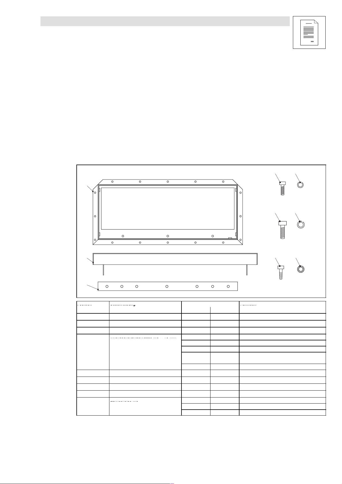
1.2 Lieferumfang
Vorwort
0
1
2
Position Beschreibung
Luftschleuse 1 2
Abdeckung Luftschleuse 1 1
Montageschiene 2 4 Befestigung Antriebsregler auf Montageplatte
Innensechskantschraube M6 × 16 mm
Federring M6 8 16 zu
Innensechskantschraube M8 × 25 mm 12 24 Befestigung Antriebsregler und Montageschiene
Federring M8 12 24 zu
Selbstformschraube M6 (Rittal) 16 32 Befestigung Luftschleuse am Schaltschrank
Zahnscheibe M6
3
5
4
6
78
Anzahl
E93ZWL E93ZWL2
3 3 Befestigung Abdeckung
1 1 Befestigung und Erdung Abdeckung
2 4 Befestigung Luftschleuse am Antriebsregler
1 2 Befestigung und Erdung Luftschleuse am An-
1 2 Erdung Luftschleuse am Schaltschrank
1 2 Erdung Abdeckung
1 2 Erdung Luftschleuse am Antriebsregler
1 2 Erdung Luftschleuse
Funktion
triebsregler
93ZWL020
l
E93ZWLX DE/EN/FR 1.0
1
Page 6
Sicherheitshinweise
Piktogram
m
FolgenbeiMißachtungderS
i
Show/Hide Bookmarks
Gestaltung der Sicherheitshinweise
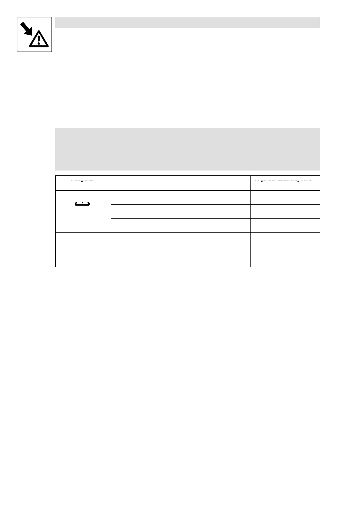
2 Sicherheitshinweise
2.1 Gestaltung der Sicherheitshinweise
Alle Sicherheitshinweise in dieser Anleitung sind einheitlich aufgebaut:
Piktogramm (kennzeichnet die Art der Gefahr)
Signalwort! (kennzeichnet die Schwere der Gefahr)
Hinweistext (beschreibt die Gefahr und gibt Hinweise, wie sie vermieden werden
kann)
Piktogramm
gefährliche elektrische Spannung
allgemeine Gefahr
Signalwort
Signalwort Bedeutung
Gefahr! Unmittelbar drohende Gefahr für Perso-
nen
Warnung! Mögliche, sehr gefährliche Situation für
Personen
Vorsicht! Mögliche, gefährliche Situation für Per-
sonen
Stop! Mögliche Sachschäden Beschädigung des Antriebssystems
Hinweis! Nützlicher Hinweis oder Tipp
Wenn Sie ihn befolgen, erleichtern Sie sich
die Handhabung des Antriebssystems.
Folgen bei Mißachtung der Si-
cherheitshinweise
Tod oder schwerste Verletzungen
Tod oder schwerste Verletzungen
Leichte Verletzungen
oder seiner Umgebung
2
E93ZWLX DE/EN/FR 1.0
l
Page 7
Installation der Luftschleuse E93ZWL
Show/Hide Bookmarks
Abmessungen Luftschleuse
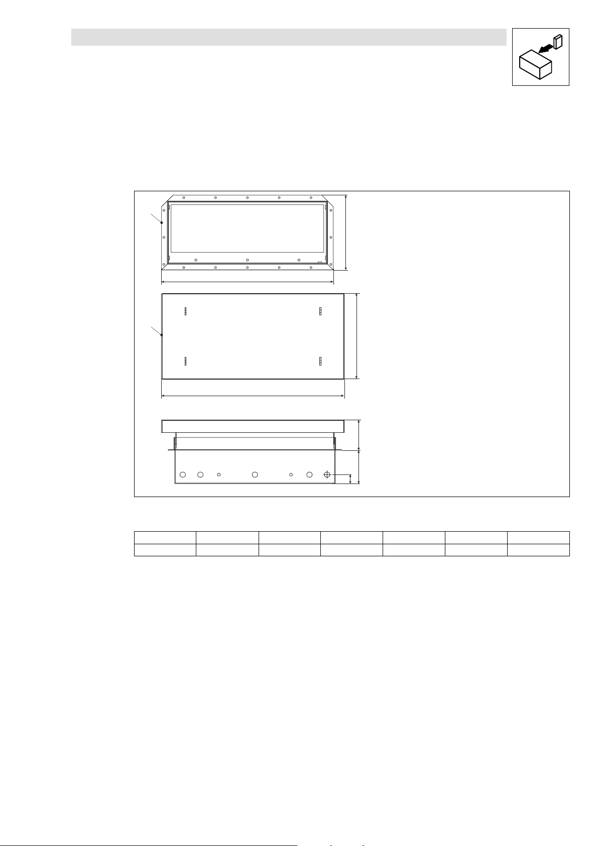
3 Installation der Luftschleuse E93ZWL
3.1 Abmessungen Luftschleuse
0
b1
a1
1
b2
a2
c3
c1
c2
Luftschleuse
Abdeckung Luftschleuse
a1 [mm]
540 584 225 275 104 28 60
a2 [mm] b1 [mm] b2 [mm] c1 [mm] c2 [mm] c3 [mm]
93ZWL011
L
E93ZWLX DE/EN/FR 1.0
3
Page 8
Installation Luftschleuse E93ZWL
Show/Hide Bookmarks
Vorbereitende Arbeiten an der Montageplatte
3.2 Vorbereitende Arbeiten an der Montageplatte
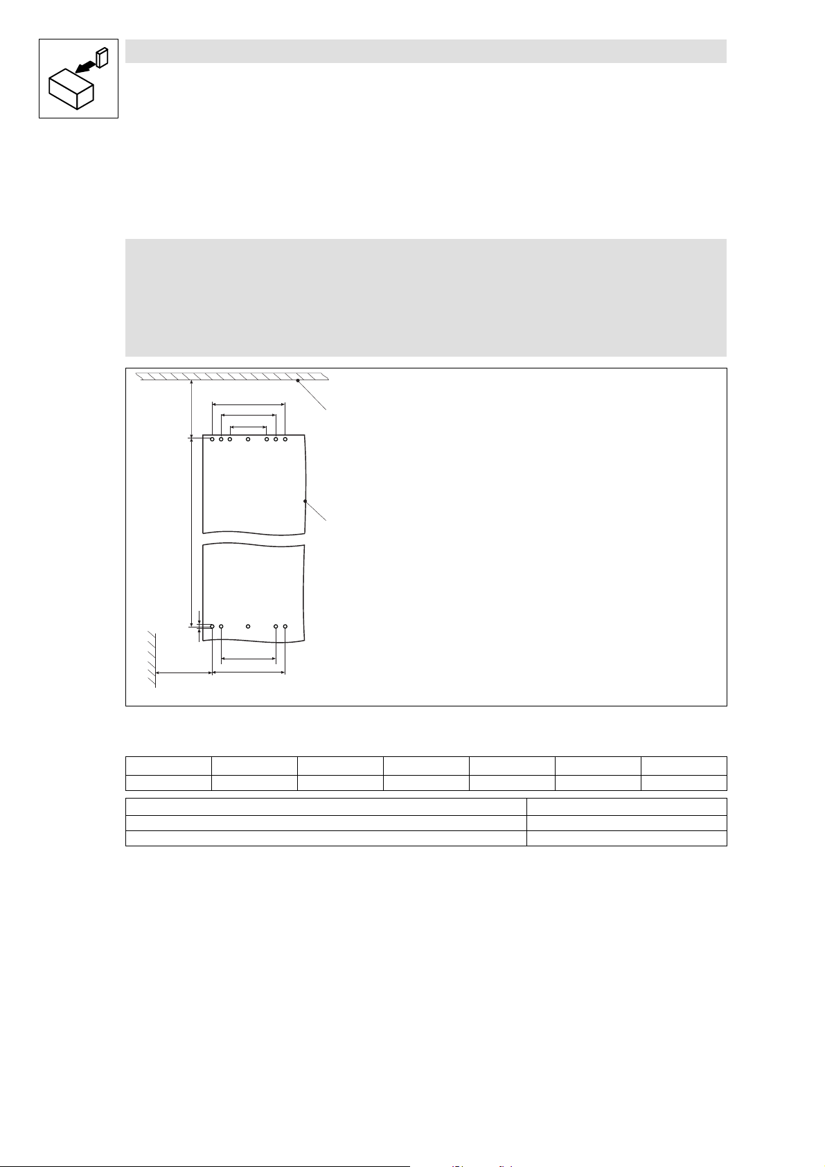
3.2.1 Bohrungen durchführen
Hinweis!
Zur einfachen Markierung der Bohrungen und der Aussparung im
Schaltschrankdach können Sie eine Schablone benutzen. Diese können Sie auch
als dxf-Datei im Internet herunterladen, im Bereich ”Downloads” unter
http://www.Lenze.de
b1
a1
a2
a3
0
1
b
d
a2
a2
a1
[mm]
a3
[mm]
a4
[mm]
b
[mm]
b1
[mm]
a4
Schaltschrankdach
Montageplatte
a1
[mm]
450 340 225 200 1005 70 9 (12x)
d
93ZWL012
[mm]
Montagefreiraum a4 Mindestabstand
Links/rechts zu ei nem anderen Antriebsregle r mit Luftschleuse 200 mm
Links/rechts zu einem anderen Antriebsregl e r ohne Luftschleuse 30 mm
z
Bohrungen entsprechend der Abbildung auf Montageplatte markieren.
z
Löcher in Montageplatte bohren.
4
E93ZWLX DE/EN/FR 1.0
l
Page 9
Installation Luftschleuse E93ZWL
Show/Hide Bookmarks
Vorbereitende Arbeiten an der Montageplatte
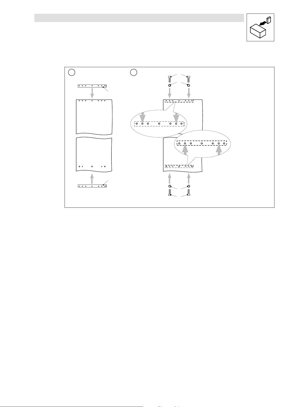
3.2.2 Montageschienenan Montageplatte befestigen
1 2
0
1
0
Montageschiene
Montageplatte
Innensechskantschraube M8 × 25 mm
Federring M8
2
3
3
2
93ZWL013
1. Montageschienen hinter Montageplatte halten.
2. Montagesschienen mit 4 Innensechskantschrauben und Federringen genau an den gezeigten
PunktenhinterMontageplattebefestigen.
l
E93ZWLX DE/EN/FR 1.0
5
Page 10
Installation Luftschleuse E93ZWL
Show/Hide Bookmarks
Vorbereitende Arbeiten am Schaltschrankdach
3.3 Vorbereitende Arbeiten am Schaltschrankdach
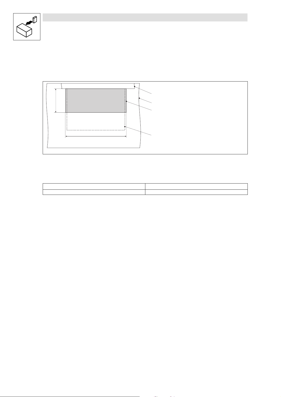
3.3.1 Aussparung im Schaltschrankdach (Draufsicht)
b
1
2
0
a
3
Montageplatte
Schaltschrankdach
Aussparung
Position Antriebsregler
a
[mm]
505 200
z
Aussparung im Schaltschrankdach markieren und Aussparung aussägen.
b
93ZWL014
[mm]
6
E93ZWLX DE/EN/FR 1.0
l
Page 11
Installation Luftschleuse E93ZWL
Show/Hide Bookmarks
Vorbereitende Arbeiten am Schaltschrankdach
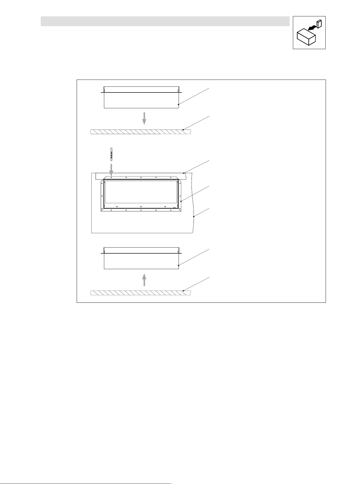
3.3.2 Befestigungslöcher für Luftschleuse in Schaltschrankdach bohren
0
1
Luftschleuse
Schaltschrankdach
Montageplatte
Æ 4.8 mm
2
0
1
0
1
93ZWL015
l
1. Luftschleuse in Aussparung im Schaltschrankdach einsetzen.
2. 16 Befestigungslöcher bohren.
3. Luftschleuse aus Schaltschrankdach herausnehmen.
E93ZWLX DE/EN/FR 1.0
7
Page 12
Installation Luftschleuse E93ZWL
Show/Hide Bookmarks
Antriebsregler und Luftschleuse montieren
3.4 Antriebsregler und Luftschleuse montieren
3.4.1 Antriebsregler auf Montageplatte befestigen
Gefahr!
Verletzungsgefahr durch hohes Gewicht des Antriebsreglers.
Transportieren Sie die Antriebsregler ausschließlich an den Ringösen und mit
geeignetem Hebezeug.
1
2
102
3
4
Ringösen
Antriebsregler
1. Antriebsregler auf Montageplattelegen.
2. Antriebsregler mit 6 Innensechskantschrauben und Federringen genau an den gezeigten
Punktenaufder Montageplattebefestigen.
8
Montageplatte
Innensechskantschraube M8 × 25 mm
E93ZWLX DE/EN/FR 1.0
Federring M8
93ZWL016
l
Page 13
Installation Luftschleuse E93ZWL
Show/Hide Bookmarks
Antriebsregler und Luftschleuse montieren
3.4.2 Luftschleuse an Montageplatte befestigen
Hinweis!
z
DieMontageplattemußim Schaltschrankhängen.
z
Lenze empfiehlt eine Dichtung zwischen Luftschleusen und Schaltschrankdach.
Die Dichtung (Meterware)befindet sich nicht im Lieferumfang der Luftschleusen.
112
0
3
2
Befestigungskragen der Luftschleuse
Dichtung
Schaltschrankdach
Innensechskantschraube M8 × 25 mm
Federring M8
1
4
93ZWL017
l
1. Dichtungen unter Befestigungskragen der Luftschleuse kleben und Luftschleuse durch
Aussparung im Schaltschrankdach führen.
2. Luftschleuse mit 2 Innensechskantschrauben und Federringen genau an den gezeigten
Punkten an der Montageplatte befestigen.
E93ZWLX DE/EN/FR 1.0
9
Page 14
Installation Luftschleuse E93ZWL
gg(
)
Show/Hide Bookmarks
Antriebsregler und Luftschleuse montieren
3.4.3 Luftschleuse am Antriebsregler und Schaltschrankdach befestigen
0
1
2
3
Selbstformschraube
Montageplatte
4
5
4
5
Luftschleuse
Schaltschrankdach
Federring M6
Innensechskantschraube M6 × 16 mm
93ZWL018
z
Luftschleuse mit 16 Selbstformschrauben am Schaltschrankdach befestigen.
z
Luftschleuse mit 2 Innensechskantschrauben und Federringen genau an den gezeigten
Punkten am Antriebsregler befestigen.
3.4.4 Luftschleuse erden
Schaltschrankdach
Zahnscheibe M6
1
2
3
0
1
4
2
3
Federring M6
Innensechskantschraube M6 × 16 mm
Erdungsleitung Schaltschrank
nicht im Lieferumfangenthalten
93ZWL22
10
1. Luftschleuse mit 1 Innensechskantschraube, Federring und Zahnscheibe genau am gezeigten
Punkt am Antriebsregler erden.
2. Luftschleuse mit 1 Innensechskantschraube, Federring, Erdungsleitung und Zahnscheibe
genau am gezeigten Punkt am Schaltschrank erden.
E93ZWLX DE/EN/FR 1.0
l
Page 15
Installation Luftschleuse E93ZWL
Show/Hide Bookmarks
Antriebsregler und Luftschleuse montieren
3.4.5 Abdeckung auf Luftschleuse befestigen
Abdeckung Luftschleuse
Innensechskantschraube M6 × 16
Federring M6
Zahnscheibe M6
0
13
213
93ZWL019
1. Abdeckung auf die Luftschleuse setzen.
2. Abdeckung mit 3 Innensechskantschrauben und Federringen an der Luftschleuse befestigen.
3. Abdeckung mit 1 Innensechskantschraube, Federring und Zahnscheibe an der Luftschleuse
erden.
l
E93ZWLX DE/EN/FR 1.0
11
Page 16
Installation der Luftschleuse E93ZWL2
Show/Hide Bookmarks
Abmessungen Luftschleuse
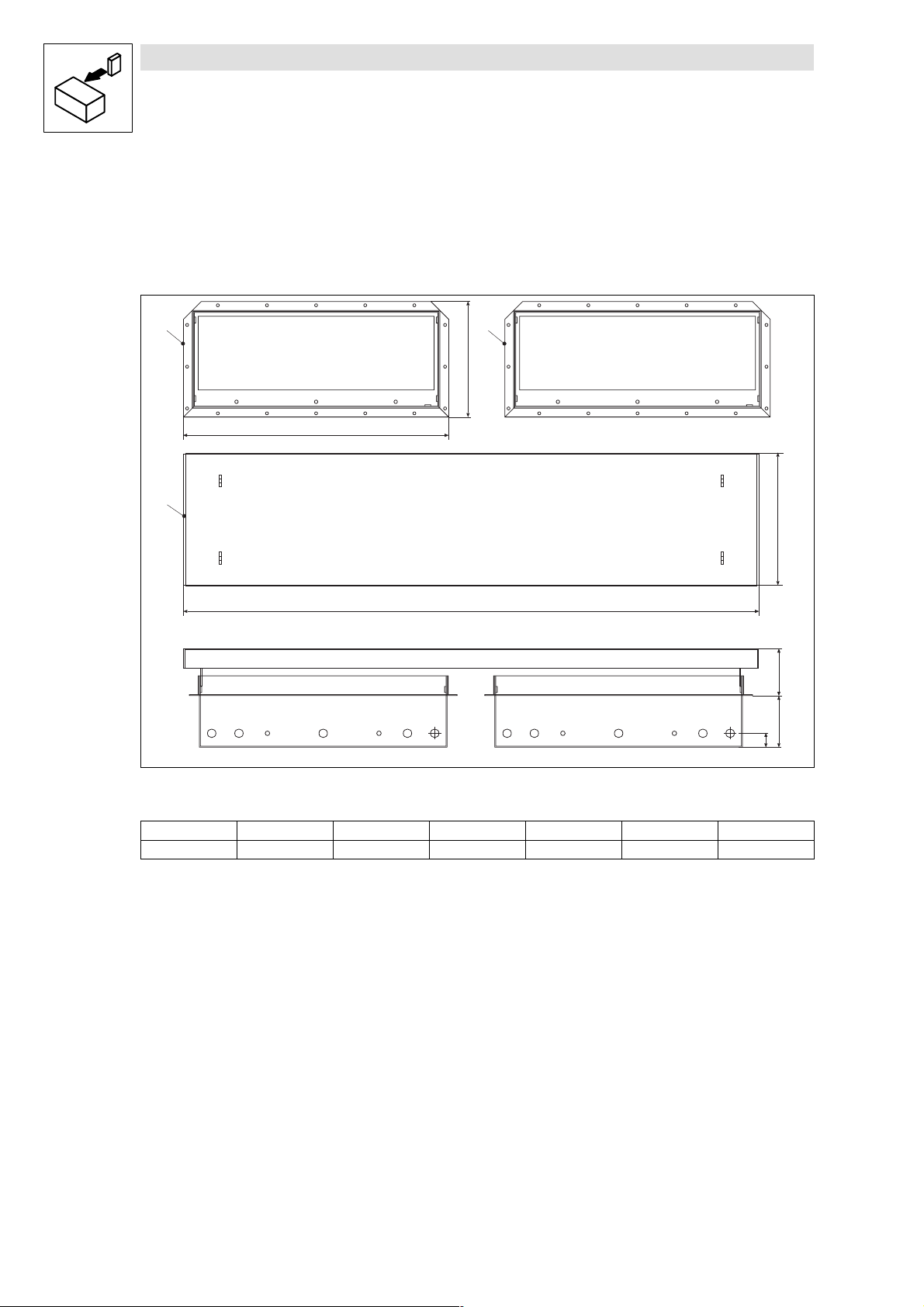
4 Installation der Luftschleuse E93ZWL2
4.1 Abmessungen Luftschleuse
00
b1
a1
1
b2
a2
Luftschleuse
Abdeckung Luftschleuse
a1 [mm]
540 1130 225 275 104 28 60
a2 [mm] b1 [mm] b2 [mm] c1 [mm] c2 [mm] c3 [mm]
c3
c1
c2
93ZWL001
12
E93ZWLX DE/EN/FR 1.0
L
Page 17
Installation Luftschleuse E93ZWL2
Show/Hide Bookmarks
Vorbereitende Arbeiten an der Montageplatte
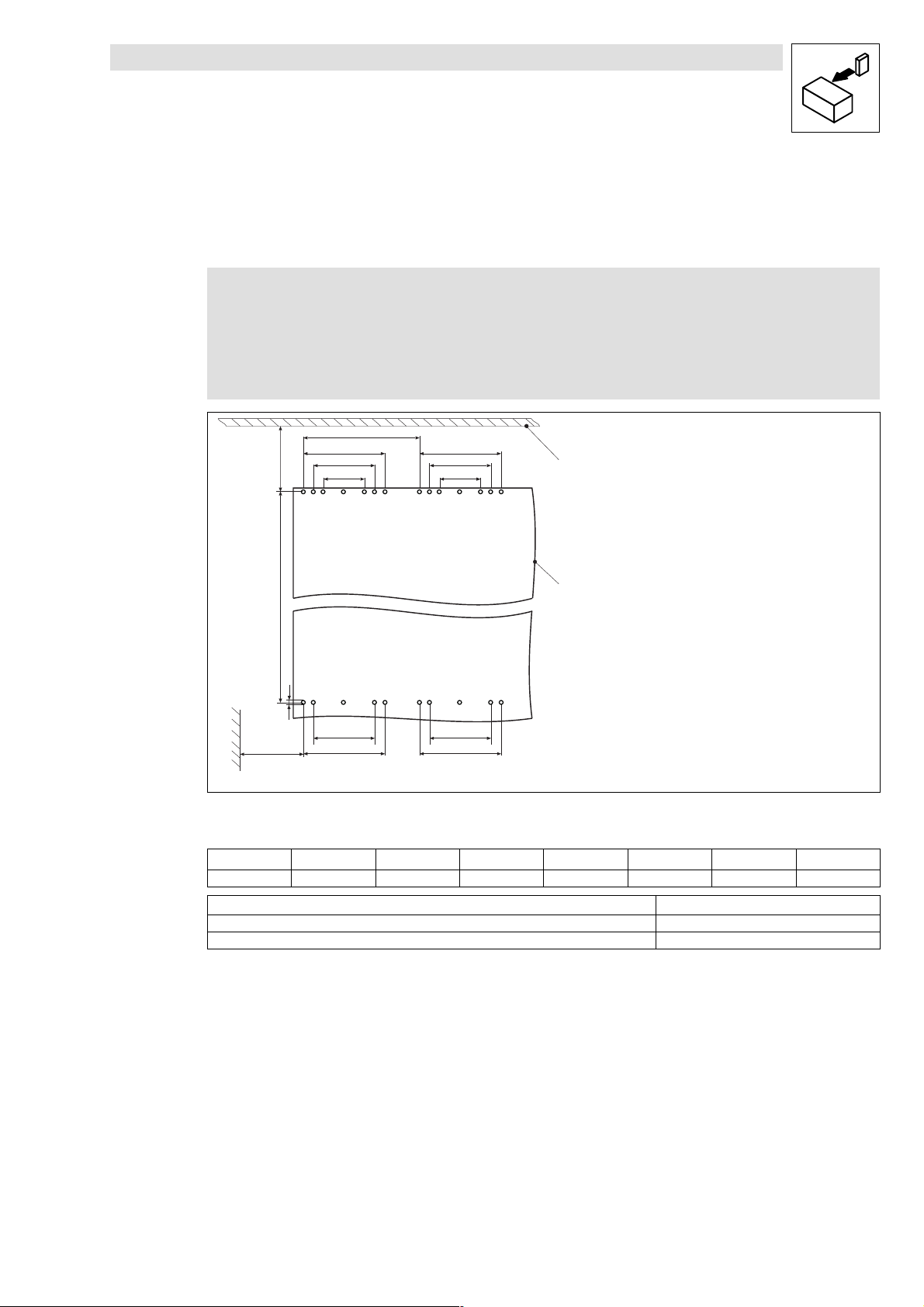
4.2 Vorbereitende Arbeiten an der Montageplatte
4.2.1 Bohrungen durchführen
Hinweis!
Zur einfachen Markierung der Bohrungen und der Aussparung im
Schaltschrankdach können Sie eine Schablone benutzen. Diese können Sie auch
als dxf-Datei im Internet herunterladen, im Bereich ”Downloads” unter
http://www.Lenze.de
a
b1
a1 a1
a2 a2
a3
a3
0
b
1
d
a2 a2
a1
a1
[mm]
a2
a4
Schaltschrankdach
Montageplatte
a
[mm]
550 450 340 225 200 1005 70 9 (24x)
Montagefreiraum a4 Mindestabstand
Links/rechts zu ei nem anderen Antriebsregle r mit Luftschleuse 200 mm
Links/rechts zu einem anderen Antriebsregl e r ohne Luftschleuse 30 mm
z
Bohrungen entsprechend der Abbildung auf Montageplatte markieren.
z
Löcher in Montageplatte bohren.
[mm]
a1
a3
[mm]
a4
[mm]
b
[mm]
b1
[mm]
d
93ZWL002
[mm]
l
E93ZWLX DE/EN/FR 1.0
13
Page 18
Installation Luftschleuse E93ZWL2
Show/Hide Bookmarks
Vorbereitende Arbeiten an der Montageplatte
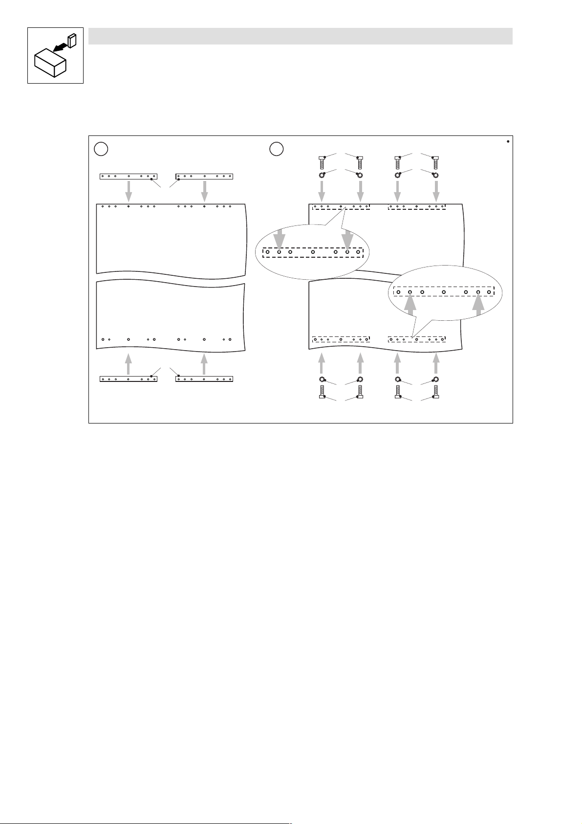
4.2.2 Montageschienenan Montageplatte befestigen
1 2
0
1
0
Montageschiene
Montageplatte
Innensechskantschraube M8 × 25 mm
Federring M8
2
3
2
3
33
22
93ZWL003
1. Montageschienen hinter Montageplatte halten.
2. Montagesschienen jeweils mit 4 Innensechskantschrauben und Federringen genau an den
gezeigtenPunktenhinter Montageplattebefestigen.
14
E93ZWLX DE/EN/FR 1.0
l
Page 19
Installation Luftschleuse E93ZWL2
Show/Hide Bookmarks
Vorbereitende Arbeiten am Schaltschrankdach
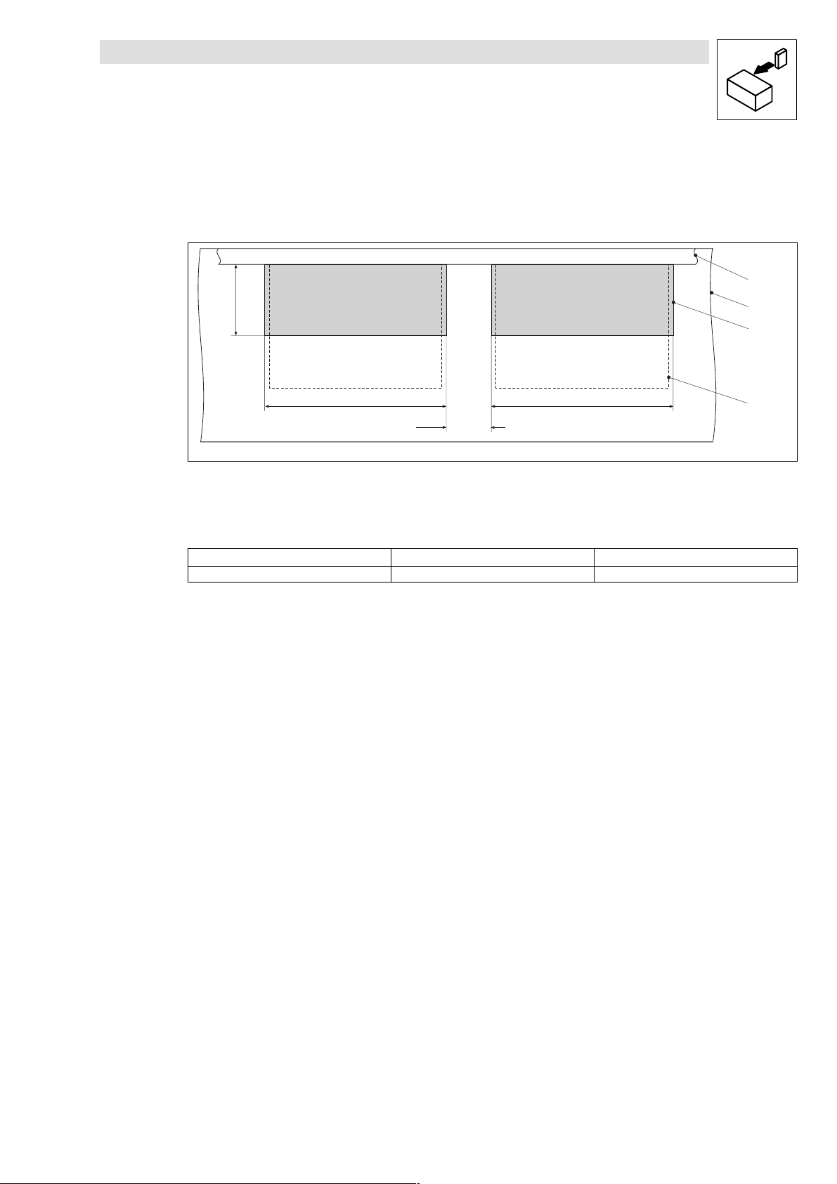
4.3 Vorbereitende Arbeiten am Schaltschrankdach
4.3.1 Aussparungen im Schaltschrankdach(Draufsicht)
b
aa
a1
Montageplatte
Schaltschrankdach
Aussparung
Position Antriebsregler
a
[mm]
505 45 200
z
Aussparungen im Schaltschrankdach markieren und Aussparungen aussägen.
a1
[mm]
b
0
1
2
3
93ZWL004
[mm]
l
E93ZWLX DE/EN/FR 1.0
15
Page 20
Installation Luftschleuse E93ZWL2
Show/Hide Bookmarks
Vorbereitende Arbeiten am Schaltschrankdach
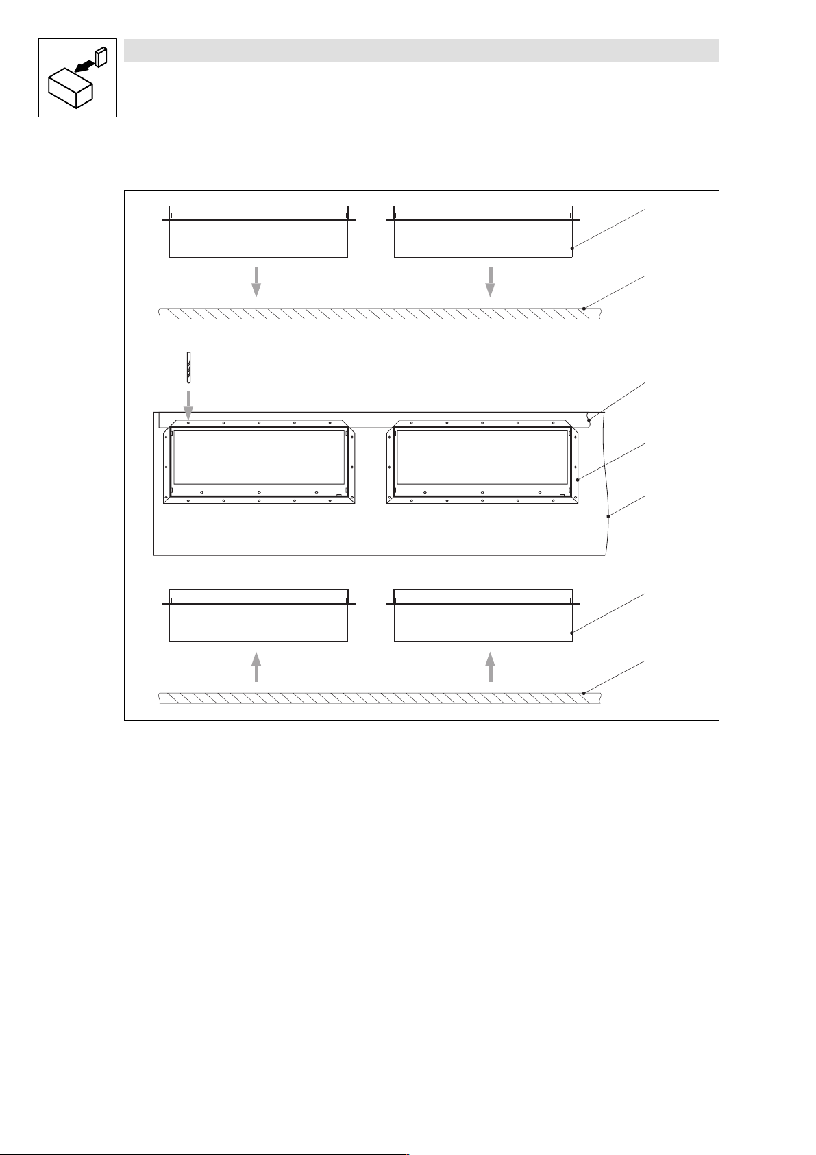
4.3.2 Befestigungslöcher für Luftschleusen in Schaltschrankdach bohren
0
1
Æ 4.8 mm
2
0
1
0
Luftschleuse
Schaltschrankdach
Montageplatte
1. Luftschleusen in Aussparungen im Schaltschrankdach einsetzen.
2. Jeweils 16 Befestigungslöcher bohren.
3. Luftschleusen aus Schaltschrankdach herausnehmen.
1
93ZWL005
16
E93ZWLX DE/EN/FR 1.0
l
Page 21

Installation Luftschleuse E93ZWL2
Show/Hide Bookmarks
Antriebsregler und Luftschleusen montieren
4.4 Antriebsregler und Luftschleusen montieren
4.4.1 Antriebsregler auf Montageplatte befestigen
Gefahr!
Verletzungsgefahr durch hohes Gewicht des Antriebsreglers.
Transportieren Sie die Antriebsregler ausschließlich an den Ringösen und mit
geeignetem Hebezeug.
l
E93ZWLX DE/EN/FR 1.0
17
Page 22
Installation Luftschleuse E93ZWL2
Show/Hide Bookmarks
Antriebsregler und Luftschleusen montieren
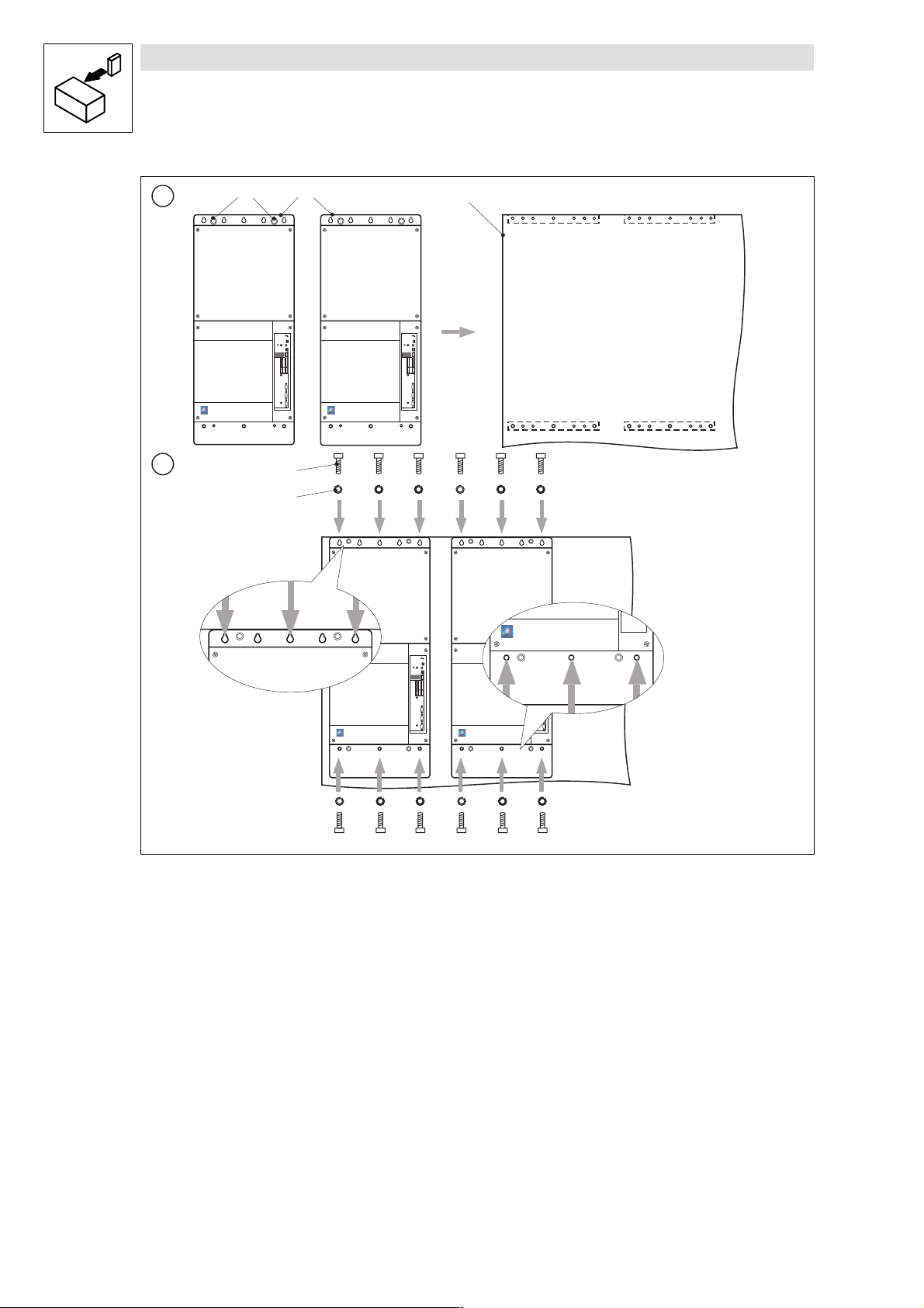
1
2
10
2
3
4
Ringösen
Antriebsregler
1. Antriebsregler auf Montageplattelegen.
2. Antriebsregler jeweils mit 6 Innensechskantschrauben und Federringen genau an den
gezeigtenPunktenaufderMontageplattebefestigen.
18
Montageplatte
Innensechskantschraube M8 × 25 mm
E93ZWLX DE/EN/FR 1.0
Federring M8
93ZWL006
l
Page 23
Installation Luftschleuse E93ZWL2
Show/Hide Bookmarks
Antriebsregler und Luftschleusen montieren
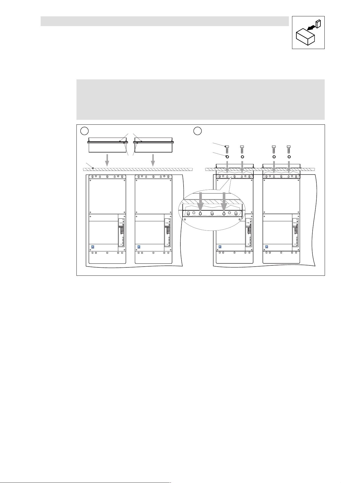
4.4.2 Luftschleusen an M ontageplatte befestigen
Hinweis!
z
DieMontageplattemußim Schaltschrankhängen.
z
Lenze empfiehlt eine Dichtung zwischen Luftschleusen und Schaltschrankdach.
Die Dichtung (Meterware)befindet sich nicht im Lieferumfang der Luftschleusen.
112
0
3
2
Befestigungskragen der Luftschleuse
Dichtung
Schaltschrankdach
Innensechskantschraube M8 × 25 mm
Federring M8
1
4
93ZWL007
l
1. Dichtungen unter Befestigungskragen der Luftschleusen kleben und Luftschleusen durch
Aussparungen im Schaltschrankdach führen.
2. Luftschleusen jeweils mit 2 Innensechskantschrauben und Federringen genau an den
gezeigten Punkten an der Montageplatte befestigen.
E93ZWLX DE/EN/FR 1.0
19
Page 24
Installation Luftschleuse E93ZWL2
gg(
)
Show/Hide Bookmarks
Antriebsregler und Luftschleusen montieren
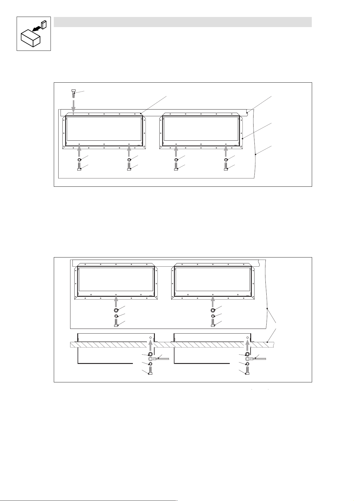
4.4.3 Luftschleusenam Antriebsregler und Schaltschrankdach befestigen
0
4
5
Selbstformschraube
Montageplatte
z
Luftschleusen jeweils mit 16 Selbstformschrauben am Schaltschrankdach befestigen.
z
Luftschleusen jeweils mit 2 Innensechskantschrauben und Federringen genau an den
gezeigten Punkten mit dem Antriebsregler verbinden.
4.4.4 Luftschleusenerden
4
5
Luftschleuse
Schaltschrankdach
4
5
12
2
3
4
5
Federring M6
Innensechskantschraube M6 × 16 mm
93ZWL008
11
22
33
0
1
2
3
Schaltschrankdach
Zahnscheibe M6
1. Luftschleusen jeweils mit 1 Innensechskantschraube, Federring und Zahnscheibe genau am
gezeigten Punkt am Antriebsregler erden.
2. Luftschleusen jeweils mit 1 Innensechskantschraube, Federring, Erdungsleitung und
Zahnscheibe genau am gezeigten Punkt am Schaltschrank erden.
Federring M6
Innensechskantschraube M6 × 16 mm
4
1
4
2
3
Erdungsleitung Schaltschrank
nicht im Lieferumfangenthalten
93ZWL23
20
E93ZWLX DE/EN/FR 1.0
l
Page 25

Installation Luftschleuse E93ZWL2
Show/Hide Bookmarks
Antriebsregler und Luftschleusen montieren
4.4.5 Abdeckung auf Luftschleusen befestigen
Abdeckung Luftschleuse
Innensechskantschraube M6 × 16
Federring M6
Zahnscheibe M6
0
13
213
93ZWL009
1. Abdeckung auf die Luftschleusen setzen.
2. Abdeckung mit 3 Innensechskantschrauben und Federringen an den Luftschleusen
befestigen.
3. Abdeckung mit 1 Innensechskantschraube, Federring und Zahnscheibe an der Luftschleuse
erden.
l
E93ZWLX DE/EN/FR 1.0
21
Page 26

This documentation is valid for air locks with the type designations:
Show/Hide Bookmarks
E93 ZWL E93 ZWL2
Frequency inverter:
EVF9335-EV ... EVF9338-EV
EVF9335-EVVxxx ... EVF9338-EVVxxx
Servo inverter:
EVS9335-ESVxxx ... EVS9338-ESVxxx
Read the Mounting Instructions before you start working!
For easy mounting of the air lock keep to the follo wing sequence:
Step
1 Drill bore holes E 4 E 13
2 Fix mounting rail to mounting plate E 5 E 14
3 Saw recess into top of control cabinet E 6 E 15
4 Drill fixing holes for air lock into top of control cabinet E 7 E 16
5 Fix controller on mounting plate E 8 E 17
6 Fix air lock to mounting pla te E 9 E 18
7 Fix air lock to top of control cabinet E 10 E 19
8 Ground air lock E 10 E 19
8 Fix cover on air lock E 11 E 20
Please observe all safety information given!
Procedure E93 ZWL E93 ZWL2
Frequency inverter:
EVF9381-EV ... EVF9383-EV
EVF9381-EVVxxx ... EVF9383-EVVxxx
Servo inverter:
EVS9381-ESVxxx ... EVS9383-ESVxxx
2003 Lenze Drive Systems GmbH
1.0 08/2003 TD23
Page 27

Contents
Show/Hide Bookmarks
1Preface 1.............................................................
1.1 About these Mounting Instructions 1.................................................
1.2 Scope of supply 1..............................................................
2 Safety instructions 2....................................................
2.1 Layout of the safety instructions 2...................................................
3 Installation of the E93ZWL air lock 3.......................................
3.1 Dimensions of the air lock 3.......................................................
3.2 Preparations at the mounting plate 4.................................................
3.2.1 Drill bore holes 4.......................................................
3.2.2 Fix mounting rails to mounting plate 5........................................
3.3 Preparations at the top of the control cabinet 6.........................................
3.3.1 Recess in top of control cabinet (top view) 6..................................
3.3.2 Drill fixing holes for air lock into top of control cabinet 7..........................
3.4 Mounting of controller and air lock 8.................................................
3.4.1 Fix controller on mounting plate 8...........................................
3.4.2 Fix air lock to mounting plate 9.............................................
3.4.3 Fix air lock to controller and to top of control cabinet 10...........................
3.4.4 Ground air lock 10.......................................................
3.4.5 Fix cover on air lock 11...................................................
4 Installation of the E93ZWL2 air lock 12......................................
4.1 Dimensions of the air lock 12.......................................................
4.2 Preparations at the mounting plate 13.................................................
4.2.1 Drill bore holes 13.......................................................
4.2.2 Fix mounting rails to mounting plate 14........................................
4.3 Preparations at the top of the control cabinet 15.........................................
4.3.1 Recesses in top of control cabinet (top view) 15.................................
4.3.2 Drill fixing holes for air locks into top of control cabinet 16.........................
4.4 Mounting of controllers and air locks 17...............................................
4.4.1 Fix controllers on mounting plate 17..........................................
4.4.2 Fix air locks to mounting plate 18............................................
4.4.3 Fix air locks to controllers and to top of control cabinet 19.........................
4.4.4 Ground air locks 19......................................................
4.4.5 Fix cover on air locks 20..................................................
l
E93ZWLX DE/EN/FR 1.0
i
Page 28

Contents
Show/Hide Bookmarks
ii
E93ZWLX DE/EN/FR 1.0
l
Page 29

1 Preface
PositionDescription
Functio
n
HexagonsocketscrewM6×16mm
ToothlockwasherM6
Show/Hide Bookmarks
1.1 About these Mounting Instructions
z
TheseMountingInstructions serveas basis forsafety-oriented operationon and with theair
lock and contain safety instructions that have to be observed.
z
The Mounting Instructions must always be complete and in perfectly readable condition.
1.2 Scope of s upply
Preface
0
1
2
Position Description
Air lock 1 2
Cover of air lock 1 1
Mounting rail 2 4 Fixing of controller on mounting plate
Hexagon socket screw M6 × 16 mm
Spring washer M6 8 16 See
Hexagon socket screw M8 × 25 mm 12 24 Fixing of controller and mounting rail
Spring washer M8 12 24 See
Self-cutting screw M6 (Rittal) 16 32 Fixing of air lock to control cabinet
Tooth lock washer M6
3
5
4
6
78
Amount
E93ZWL E93ZWL2
3 3 Fixing of cover
1 1 Fixing and grounding of cover
2 4 Fixing of air lock to controller
1 2 Fixing and grounding of air lock to controller
1 2 Grounding of air lock at control cabinet
1 2 Grounding of cover
1 2 Grounding of air lock at controller
1 2 Grounding of air lock
Function
93ZWL020
l
E93ZWLX DE/EN/FR 1.0
1
Page 30

Safety instructions
Show/Hide Bookmarks
Layout of the safety instructions
2 Safety instructions
2.1 Layout of the safety instructions
All safety information given in these Instructions have got the same layout:
Pic tograph (indicatesthetype of danger)
Signal word!
Note (describes the danger and explains how to avoid it)
(indicates the severity of danger)
Pictograph
Dangerous electrical voltage
General danger
Signal word
Signal word Meaning
Danger! Impending danger for persons Death or most severe injuries
Warning! Possible, very dangerous situation for
persons
Caution! Possible, dangerous situation for
persons
Stop! Possible material damage Damage of the drive system or its
Note! Useful note or tip
If you o bserve it, handling of the drive
system will be easier.
Possible consequences if the
safety information are
disregarded
Death or most severe injuries
Injuries
surroundings
2
E93ZWLX DE/EN/FR 1.0
l
Page 31

Installation of the E93ZWL air lock
Show/Hide Bookmarks
Dimensions of the air lock
3 Installation of the E93ZWL air lock
3.1 Dimensions of the air lock
0
b1
a1
1
b2
a2
c3
c1
c2
Air lock
Cover of airlock
a1 [mm]
540 584 225 275 104 28 60
a2 [mm] b1 [mm] b2 [mm] c1 [mm] c2 [mm] c3 [mm]
93ZWL011
L
E93ZWLX DE/EN/FR 1.0
3
Page 32

Installation of the E93ZWL air lock
Show/Hide Bookmarks
Preparations at the mounting plate
3.2 Preparations at the mounting plate
3.2.1 Drill bore holes
Note!
You can use a template for easy marking of the bore holes and the recess at the top
of thecontrolcabinet. Thistemplatecanbe foundin theInternetas dxf-fileunder
”Download” at
http://www.Lenze.de
b1
a1
a2
a3
0
1
b
d
a2
a2
a1
[mm]
a3
[mm]
a4
[mm]
b
[mm]
b1
[mm]
a4
Top of control c abinet
Mounting plate
a1
[mm]
450 340 225 200 1005 70 9 (12x)
d
93ZWL012
[mm]
Working clearance a4 Minimum clearance
Left/right to another controller with air lock 200 mm
Left/right to another controller without air lock 30 mm
z
Marktheboreholeson the mountingplate accordingto t he figure.
z
Drill the holes into the mounting plate.
4
E93ZWLX DE/EN/FR 1.0
l
Page 33

Installation of the E93ZWL air lock
Show/Hide Bookmarks
Preparations at the mounting plate
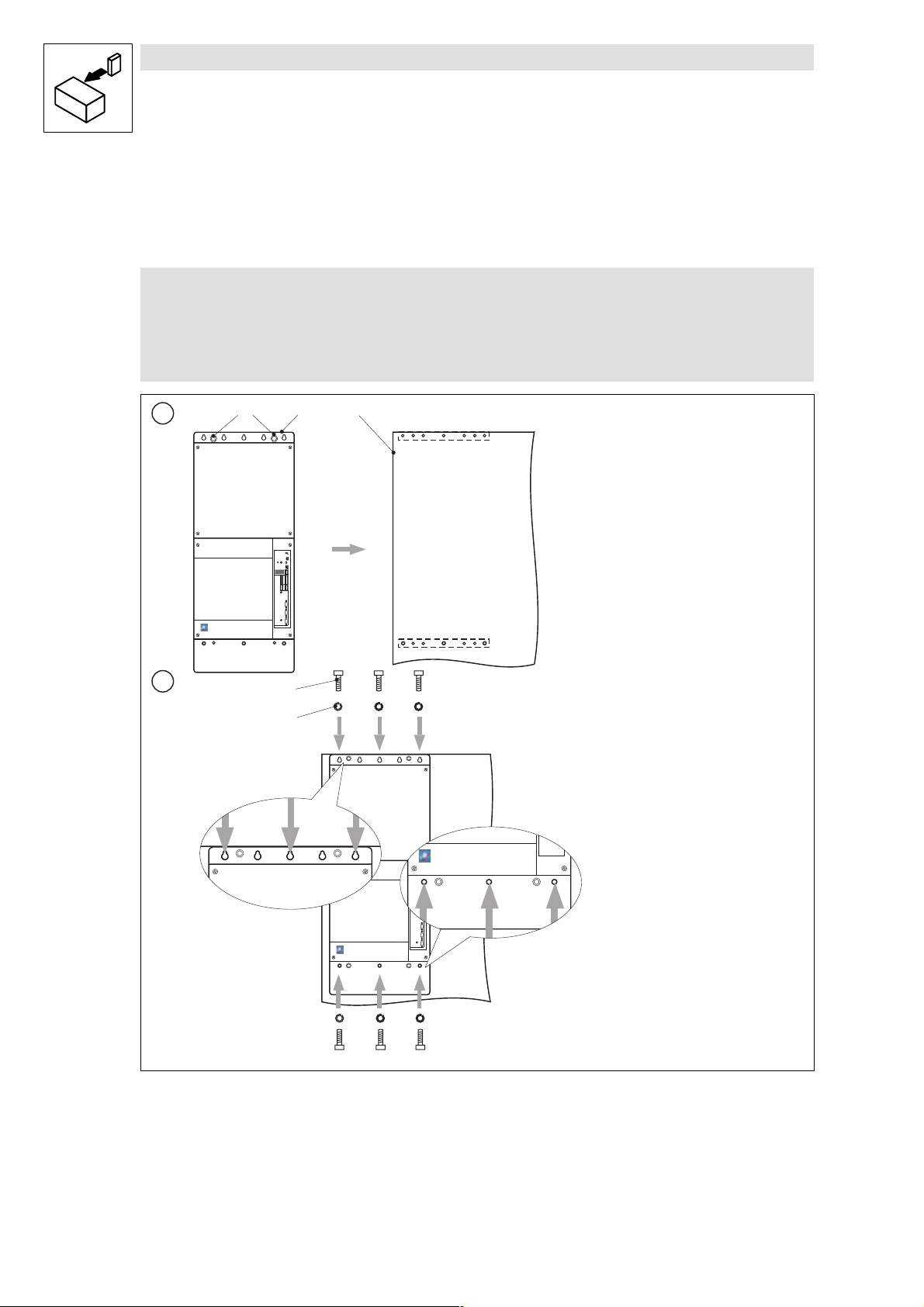
3.2.2 Fix mounting rails to mounting plate
1 2
0
1
0
Mounting rail
Mounting plate
Hexagonsocket screw M8 × 25 mm
Spring washer M8
2
3
3
2
93ZWL013
1. Hold the mounting rails behind the mounting plate.
2. F i xthe mounting rails at the back of the mounting plate exactly at the illustrated points using 4
hexagon socket screws and spring washers.
l
E93ZWLX DE/EN/FR 1.0
5
Page 34

Installation of the E93ZWL air lock
Show/Hide Bookmarks
Preparations at the top of the control cabinet
3.3 Preparations at the top of the control cabinet
3.3.1 Recess in top of control cabinet (top view)
b
1
2
0
a
3
Mounting plate
Top of control c abinet
Recess
Position of the controller
a
[mm]
505 200
z
Mark the recess at the top of the control cabinet and saw it out.
b
93ZWL014
[mm]
6
E93ZWLX DE/EN/FR 1.0
l
Page 35

Installation of the E93ZWL air lock
Show/Hide Bookmarks
Preparations at the top of the control cabinet
3.3.2 Drill fixing holes for air lock into top of control cabinet
0
1
Air lock
Top of control c abinet
Mounting plate
Æ 4.8 mm
2
0
1
0
1
93ZWL015
l
1. Insert theairlock intotherecessin thetop of thec ontrolcabinet.
2. Drill16 fixing holes.
3. Take the air lock out of the top of the control cabinet.
E93ZWLX DE/EN/FR 1.0
7
Page 36

Installation of the E93ZWL air lock
Show/Hide Bookmarks
Preparations at the top of the control cabinet
3.4 Mounting of controller and air lock
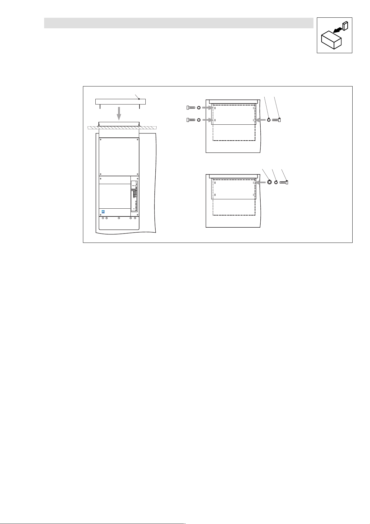
3.4.1 Fix controller on mounting plate
Danger!
Risk of injurydue to thehighweight of thec ontroller.
The controller has to be carried using the eyebolts and an adequate lifting tool.
1
2
102
3
4
Eyebolts
Controller
1. Put the controller on the mounting plate.
2. F i xthe controller on the mounting plate exactly at the illustrated points using 6 hexagon
socket screws and spring washers.
8
Mounting plate
Hexagonsocket screw M8 × 25 mm
E93ZWLX DE/EN/FR 1.0
Spring washer M8
93ZWL016
l
Page 37

Installation of the E93ZWL air lock
Show/Hide Bookmarks
Preparations at the top of the control cabinet
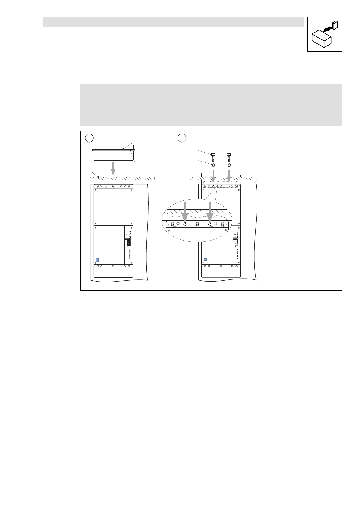
3.4.2 Fix air lock to mounting plate
Note!
z
The mounting plate must be suspended in the control cabinet.
z
Lenze recommends to install a gasket between the air lock and the top of the
control cabinet. The gasket (yard ware) is not part of the items supplied with the
air locks.
112
0
3
2
Fixing collar of air lock
Gasket
Top of control c abinet
Hexagonsocket screw M8 × 25 mm
Spring washer M8
1
4
93ZWL017
l
1. Gluethe gasket under the fixing collar of the air lock and insert the air lock into the recess in
thetop of the control cabinet.
2. Fix the air lock to the mounting plate exactly at the illustrated points using 2 hexagon socket
screws and spring washers.
E93ZWLX DE/EN/FR 1.0
9
Page 38

Installation of the E93ZWL air lock
b
inet
(notpar
tofthei
t
Show/Hide Bookmarks
Preparations at the top of the control cabinet
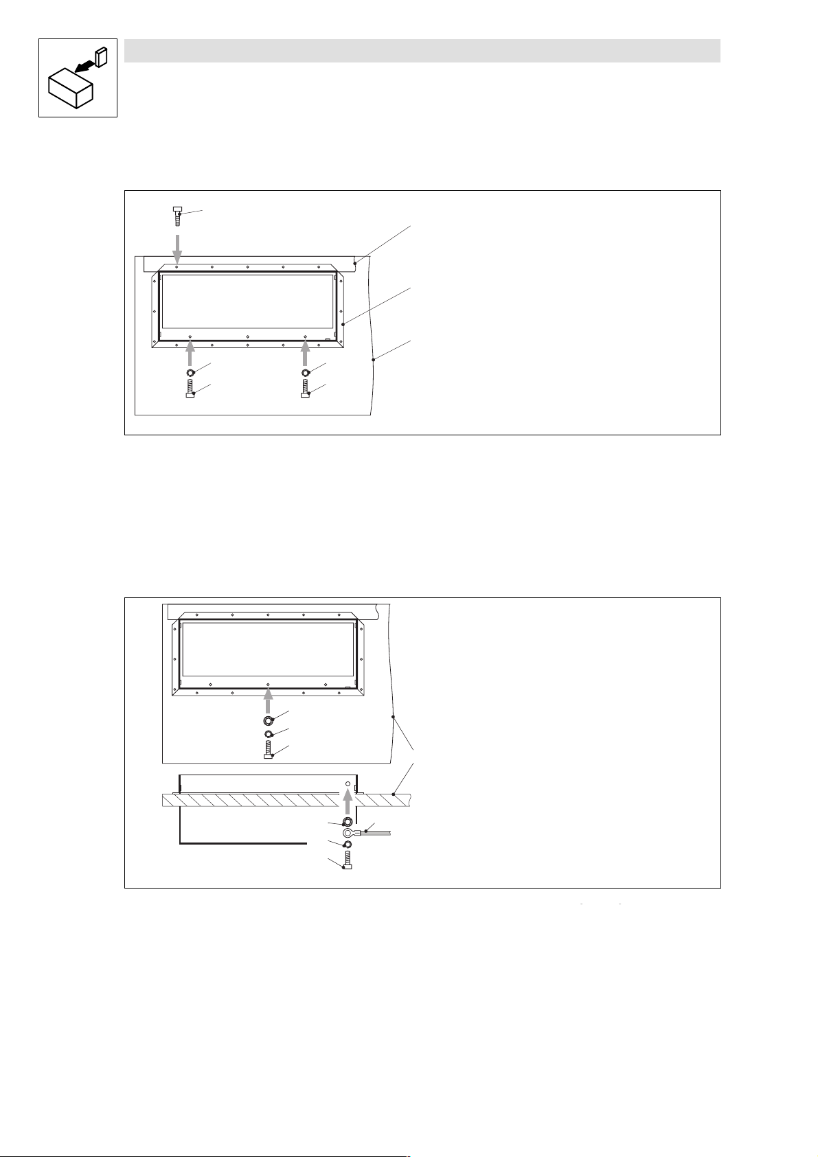
3.4.3 Fix air lock to controller and to top of control cabinet
0
1
2
3
Self-cutting screw
Mounting plate
4
5
4
5
Air lock
Top of control c abinet
Spring washer M6
Hexagonsocket screw M6 × 16 mm
93ZWL018
z
Fix the air lock to the top of the control cabinet using 16 self-cutting screws.
z
Fix the air lock to the controller exactly at the illustrated points using 2 hexagon socket screws
and spring washers.
3.4.4 Ground air lock
Top of control c abinet
Tooth lock washerM6
1
2
3
0
1
4
2
3
Spring washer M6
Hexagonsocket screw M6 × 16 mm
Grounding conductor of c ont rol
ca
supplied)
p
93ZWL22
ems
10
1. Ground the air lock exactly at the illustrated point of the controller using 1 hexagon socket
screw, spring washer and tooth lock washer.
2. Ground the air lock exactly at the illustrated point of the control cabinet using 1 hexagon
socket screw, spring washer, grounding conductor and t ooth lock washer.
E93ZWLX DE/EN/FR 1.0
l
Page 39

3.4.5 Fix cover on air lock
Show/Hide Bookmarks
Installation of the E93ZWL air lock
Preparations at the top of the control cabinet
Cover of airlock
Hexagonsocket screw M6 × 16
Spring washer M6
Tooth lock washerM6
0
13
213
93ZWL019
1. Put the cover on the air lock.
2. Fix the cover to the air lock using 3 hexagon socket screws and spring washers.
3. Ground the cover at the air lock using 1 hexagon socket screw, spring washer and tooth lock
washer.
l
E93ZWLX DE/EN/FR 1.0
11
Page 40

Installation of the E93ZWL2 air lock
Show/Hide Bookmarks
Dimensions of the air lock
4 Installation of the E93ZWL2 air lock
4.1 Dimensions of the air lock
00
b1
a1
1
b2
a2
Air lock
Cover of airlock
a1 [mm]
540 1130 225 275 104 28 60
a2 [mm] b1 [mm] b2 [mm] c1 [mm] c2 [mm] c3 [mm]
c3
c1
c2
93ZWL001
12
E93ZWLX DE/EN/FR 1.0
L
Page 41

Installation of the E93ZWL2 air lock
Show/Hide Bookmarks
Preparations at the mounting plate
4.2 Preparations at the mounting plate
4.2.1 Drill bore holes
Note!
You can use a template for easy marking of the bore holes and the recess at the top
of thecontrolcabinet. Thistemplatecanbe foundin theInternetas dxf-fileunder
”Download” at
http://www.Lenze.de
a
b1
a1 a1
a2 a2
a3
a3
0
b
1
d
a2 a2
a1
a1
[mm]
a2
a4
Top of control c abinet
Mounting plate
a
[mm]
550 450 340 225 200 1005 70 9 (24x)
Working clearance a4 Minimum clearance
Left/right to another controller with air lock 200 mm
Left/right to another controller without air lock 30 mm
z
Marktheboreholeson the mountingplate accordingto t he figure.
z
Drill the holes into the mounting plate.
[mm]
a1
a3
[mm]
a4
[mm]
b
[mm]
b1
[mm]
d
93ZWL002
[mm]
l
E93ZWLX DE/EN/FR 1.0
13
Page 42

Installation of the E93ZWL2 air lock
Show/Hide Bookmarks
Preparations at the mounting plate
4.2.2 Fix mounting rails to mounting plate
1 2
0
1
0
Mounting rail
Mounting plate
Hexagonsocket screw M8 × 25 mm
Spring washer M8
2
3
2
3
33
22
93ZWL003
1. Hold the mounting rails behind the mounting plate.
2. F i xthe mounting rails at the back of the mounting plate exactly at the illustrated points using 4
hexagon socket screws and spring washers for each pair of rails.
14
E93ZWLX DE/EN/FR 1.0
l
Page 43

Installation of the E93ZWL2 air lock
Show/Hide Bookmarks
Preparations at the top of the control cabinet
4.3 Preparations at the top of the control cabinet
4.3.1 Recesses in top of control cabinet (top view)
b
aa
a1
Mounting plate
Top of control c abinet
Recess
Position of the controller
a
[mm]
505 45 200
z
Mark the recesses at the top of the control cabinet and saw them out.
a1
[mm]
b
0
1
2
3
93ZWL004
[mm]
l
E93ZWLX DE/EN/FR 1.0
15
Page 44

Installation of the E93ZWL2 air lock
Show/Hide Bookmarks
Preparations at the top of the control cabinet
4.3.2 Drillfixing holes for air locks into top of control cabinet
0
1
Æ 4.8 mm
2
0
1
0
Air lock
Top of control c abinet
Mounting plate
1. Insert the air locks into the recesses in the top of the control cabinet.
2. Drill16 fixing holes for each air lock.
3. Take the airlocks out of t he top of thec ontrol cabinet.
1
93ZWL005
16
E93ZWLX DE/EN/FR 1.0
l
Page 45

Installation of the E93ZWL2 air lock
Show/Hide Bookmarks
Mounting of controllers and air locks
4.4 Mounting of controllers and air locks
4.4.1 Fix controllers on mounting plate
Danger!
Risk of injurydue to thehighweight of thec ontroller.
The controller has to be carried using the eyebolts and an adequate lifting tool.
1
2
10
2
3
4
l
Eyebolts
Controller
1. Put the controllers on the mounting plate.
2. F i xeach controller on the mounting plate exactly at the illustrated points using 6 hexagon
socket screws and spring washers.
Mounting plate
Hexagonsocket screw M8 × 25 mm
E93ZWLX DE/EN/FR 1.0
Spring washer M8
93ZWL006
17
Page 46

Installation of the E93ZWL2 air lock
Show/Hide Bookmarks
Mounting of controllers and air locks
4.4.2 Fix air locks to mounting plate
Note!
z
The mounting plate must be suspended in the control cabinet.
z
Lenze recommends to install gaskets between the air locks and the top of the
control cabinet. The gasket (yard ware) is not part of the items supplied with the
air locks.
112
0
3
2
Fixing collar of air lock
Gasket
Top of control c abinet
Hexagonsocket screw M8 × 25 mm
Spring washer M8
1
4
93ZWL007
1. Gluethe gaskets under the fixing collars of the air locks and insert the air locks into the
recesses in the top of the control cabinet.
2. F i xeach air lock to the mounting plate exactly at the illustrated points using 2 hexagon socket
screws and spring washers.
18
E93ZWLX DE/EN/FR 1.0
l
Page 47

Installation of the E93ZWL2 air lock
b
inet
(notpar
tofthei
t
Show/Hide Bookmarks
Mounting of controllers and air locks
4.4.3 Fix air locks to controllers and to top of control cabinet
0
4
5
Self-cutting screw
Mounting plate
z
Fixeachairlock to the top of thecontrolcabinet using16 self-cuttingscrews.
z
Fix each air lock to the controller exactly at the illustrated points using 2 hexagon socket
screws and spring washers.
4.4.4 Ground air locks
4
5
Air lock
Top of control c abinet
4
5
4
5
Spring washer M6
Hexagonsocket screw M6 × 16 mm
12
2
3
93ZWL008
11
22
33
0
1
2
3
Top of control c abinet
Tooth lock washerM6
1. Ground each air lock exactly at the illustrated point of the controller using 1 hexagon socket
screw, spring washer and tooth lock washer.
2. Ground each air lock exactly at the illustrated point of the control cabinet using 1 hexagon
socket screw, spring washer, grounding conductor and t ooth lock washer.
Spring washer M6
Hexagonsocket screw M6 × 16 mm
4
1
4
2
3
Grounding conductor of c ont rol
ca
supplied)
p
ems
93ZWL23
l
E93ZWLX DE/EN/FR 1.0
19
Page 48

Installation of the E93ZWL2 air lock
Show/Hide Bookmarks
Mounting of controllers and air locks
4.4.5 Fix cover on air locks
Cover of airlock
Hexagonsocket screw M6 × 16
Spring washer M6
Tooth lock washerM6
0
13
213
93ZWL009
1. Put the cover on the air locks.
2. Fix the cover to the air locks using 3 hexagon socket screws and spring washers.
3. Ground the cover at the air lock using 1 hexagon socket screw, spring washer and tooth lock
washer.
20
E93ZWLX DE/EN/FR 1.0
l
Page 49

Installation of the E93ZWL2 air lock
Show/Hide Bookmarks
Mounting of controllers and air locks
l
E93ZWLX DE/EN/FR 1.0
21
Page 50

Cette documentation s’applique aux trappes à air des versions suivantes :
Show/Hide Bookmarks
E93 ZWL E93 ZWL2
convertisseurs de fréquence :
EVF9335-EV ... EVF9338-EV
EVF9335-EVVxxx ... EVF9338-EVVxxx
servovariateurs :
EVS9335-ESVxxx ... EVS9338-ESVxxx
Lire attentivement les instructions de montage avant toute action !
Pour un montage réussi de la trappe à air, respecter l’ordre des opérations suivant :
Etape
1 Percer les trous E 4 E 13
2 Fixer l ’embase à la plaque de montage E 5 E 14
3 Réaliser l’ouverture dans le toit de l’armoire électrique E 6 E 15
4 Percer les trous destinés au montage de la trappe à air dans le toit de l’armoire électrique E 7 E 16
5 Fixer le variateur de vitesse sur la plaque de montage E 8 E 17
6 Fixer l a trappe à ai r à la plaque de montage E 9 E 19
7 Fixer la trappe à air au toit de l’armoire électrique E 10 E 20
8 Relierlatrappeàairàlaterre E 10 E 21
9 Fixerlecouverclesurlatrappeàair E 11 E 22
Respecter les consignes de sécurité !
Opération E93 ZWL E93 ZWL2
convertisseurs de fréquence :
EVF9381-EV ... EVF9383-EV
EVF9381-EVVxxx ... EVF9383-EVVxxx
servovariateurs :
EVS9381-ESVxxx ... EVS9383-ESVxxx
2003 Lenze Drive Systems GmbH
1.0 08/2003 TD23
Page 51

Sommaire
Show/Hide Bookmarks
1 Avant-propos 1.........................................................
1.1 Comment utiliser ces instructions de montage 1.........................................
1.2 Equipement livré 1..............................................................
2 Consignes de sécurité 2..................................................
2.1 Présentation des consignes de sécurité 2..............................................
3 Installation de la trappe à air E93ZWL 3....................................
3.1 Dimensionsdelatrappeàair 3....................................................
3.2 Préparation de la plaque de montage 4...............................................
3.2.1 Percer les trous 4.......................................................
3.2.2 Fixer les embases à la plaque de montage 5...................................
3.3 Préparation du toit de l’armoire électrique 6...........................................
3.3.1 Ouverture dans le toit de l’armoire électrique (vue du haut) 6......................
3.3.2 Percer les trous destinés au montage de la trappe à air dans le toit
de l’armoire électrique 7.................................................
3.4 Monter le variateur de vitesse et la trappe à air 8........................................
3.4.1 Fixer le variateur de vitesse sur la plaque de montage 8..........................
3.4.2 Fixer la trappe à air à la plaque de montage 9..................................
3.4.3 Fixer la trappe à air au variateur de vitesse et au toit de l’armoire électrique 10..........
3.4.4 Relierlatrappeàairàlaterre 10............................................
3.4.5 Fixer le couvercle sur la trappe à air 11........................................
4 Installation de la trappe à air E93ZWL2 12...................................
4.1 Dimensionsdelatrappeàair 12....................................................
4.2 Préparation de la plaque de montage 13...............................................
4.2.1 Percer les trous 13......................................................
4.2.2 Fixer les embases à la plaque de montage 14...................................
4.3 Préparation du toit de l’armoire électrique 15...........................................
4.3.1 Ouvertures dans le toit de l’armoire électrique (vue du haut) 15.....................
4.3.2 Percer les trous destinés au montage des trappes à air dans le toit de l’armoire électrique 16
4.4 Monter plusieurs variateurs de vitesse et trappes à air 17...................................
4.4.1 Fixer les variateurs de vitesse sur la plaque de montage 17.........................
4.4.2 Fixer les trappes à air à la plaque de montage 19................................
4.4.3 Fixer les trappes à air au variateur de vitesse et au toit de l’armoire électrique 20........
4.4.4 Relier les trappes à air à la terre 21..........................................
4.4.5 Fixer le couvercle sur les trappes à air 22......................................
l
E93ZWLX DE/EN/FR 1.0
i
Page 52

Sommaire
Show/Hide Bookmarks
ii
E93ZWLX DE/EN/FR 1.0
l
Page 53

Avant-propos
PositionDescription
Fonctio
n
VisàsixpanscreuxM6×16mm
RondelledentéeM
6
Show/Hide Bookmarks
1 Avant-propos
1.1 Comment utiliser ces instructions de montage
z
Les présentes instructions de montage permettent d’utiliser en toute sécurité la trappe à air.
Les consignes de sécurité doivent impérativement être respectées.
z
Le document des instructions de montage doit être complet et lisible, en toute circonstance.
1.2 Equipement livré
0
1
2
Position Description
Trappeàair 1 2
Couvercledelatrappeàair 1 1
Embase 2 4 Fixation du variateur de vitesse sur la plaque de
VisàsixpanscreuxM6×16mm
Rondelle élastique M6 8 16 avec
VisàsixpanscreuxM8×25mm 12 24 Fixation du variateur de vitesse et de l’embase
Rondelle élastique M8 12 24 avec
Vis autotaraudeuse M6 (Rittal) 16 32 Fixation de la trappe à air à l’armoire électrique
Rondelle dentée M6
3
5
4
6
78
Quantité
E93ZWL E93ZWL2
3 3 Fixation du couvercle
1 1 Fixation et mise à la terre du couvercle
2 4 Fixation de la trappe à air au variateur de
1 2 Fixationetmiseàlaterredelatrappeàairsur
1 2 Miseàlaterredelatrappeàairsurl’armoire
1 2 Miseàlaterreducouvercle
1 2 Miseàlaterredelatrappeàairsurlevariateur
1 2 Miseàlaterredelatrappeàair
Fonction
montage
vitesse
le variateur de vitesse
électrique
de vitesse
93ZWL020
l
E93ZWLX DE/EN/FR 1.0
1
Page 54

Consignes de sécurité
Pictogramme
Risquesencourus
Show/Hide Bookmarks
Présentation des consignes de sécurité
2 Consignes de sécurité
2.1 Présentation des consignes de sécurité
Toutes les consignes de sécurité sont présentées de façon identique :
Le pictogramme annonce le type de risque.
Lemotassociéaupictogrammeindiquel’intensitédurisqueencouru
L ’explication décrit la gravité de ce risque et les moyens de l’éviter.
.
Pictogramme
Tension électrique dangereuse
Autre danger
Mot associé au pictogramme
Mot associé au
pictogramme
Danger ! Danger imminent menaçant les
personnes
Avertissement ! Situation p otentiellement très
dangereuse menaçant les personnes
Attention ! Situation potentiellement dangereuse
menaçant les personnes
Stop ! Risquesdedégâtsmatériels Endommagement du système
Remarque importante ! Conseil pratique
permettant
une manipulation plus facile du système
d’entraînement
Signification
Risques encourus
Mort ou blessures t rès graves
Mort ou blessures t rès graves
Blessures légères
d’entraînement ou de son
environnement
2
E93ZWLX DE/EN/FR 1.0
l
Page 55

Installation de la trappe à air E93ZWL
Show/Hide Bookmarks
Dimensions de la trappe à air
3 Installation de la trappe à air E93ZWL
3.1 Dimensionsdelatrappeàair
0
b1
a1
1
b2
a2
c3
c1
c2
Trappeàair
Couvercledelatrappeàair
a1 [mm]
540 584 225 275 104 28 60
a2 [mm] b1 [mm] b2 [mm] c1 [mm] c2 [mm] c3 [mm]
93ZWL011
l
E93ZWLX DE/EN/FR 1.0
3
Page 56

Installation de la trappe à air E93ZWL
Show/Hide Bookmarks
Préparation de la plaque de montage
3.2 Préparation de la plaque de montage
3.2.1 Percer les trous
Conseil !
Pour marquer en toute simplicité les trous et l’ouverture à percer dans le toit de
l’armoire électrique, vous pouvez utiliser un gabarit. Celui-ci est également
disponible sous la forme d’un fichier dxf à la rubrique ”Téléchargements” du site
http://www.Lenze.com
b1
a1
a2
a3
0
1
b
d
a2
a2
a1
[mm]
a3
[mm]
a4
[mm]
b
[mm]
b1
[mm]
a4
Toit de l’armoire électrique
Plaque de montage
a1
[mm]
450 340 225 200 1 005 70 9 (12x)
d
93ZWL012
[mm]
Espace libre de montage a4 Espacement minimal
A gauche/droite d’un autre variateur de vitesse avec trappe à air 200 mm
A gauche/droite d’un autre variateur de vitesse sans trappe à air 30 mm
z
Marquerlestrousà percerdanslaplaquede montagecomme indiquésurlafigure.
z
Percer les trous dans la plaque de montage.
4
E93ZWLX DE/EN/FR 1.0
l
Page 57

Installation de la trappe à air E93ZWL
Show/Hide Bookmarks
Préparation de la plaque de montage
3.2.2 Fixerlesembasesàlaplaquedemontage
1 2
0
1
0
Embase
Plaque de montage
VisàsixpanscreuxM8×25mm
Rondelle élastique M8
2
3
3
2
93ZWL013
1. Maintenirlesembasesderrièrelaplaquedemontage.
2. A l’aide de 4 vis à six pans creux et de 4 rondelles élastiques, fixer les embases exactement
auxpointsindiquésderrièrelaplaquedemontage.
l
E93ZWLX DE/EN/FR 1.0
5
Page 58

Installation de la trappe à air E93ZWL
Show/Hide Bookmarks
Préparation du toit de l’armoire électrique
3.3 Préparation du toit de l’armoire électrique
3.3.1 Ouverture dans le toit de l’armoire électrique (vue du haut)
b
1
2
0
a
3
Plaque de montage
Toit de l’armoire électrique
Ouverture
Emplacement du variateur de vitesse
a
[mm]
505 200
z
Marquer l’ouverture à effectuer dans le toit de l’armoire électrique et la scier.
b
93ZWL014
[mm]
6
E93ZWLX DE/EN/FR 1.0
l
Page 59

Installation de la trappe à air E93ZWL
Show/Hide Bookmarks
Préparation du toit de l’armoire électrique
3.3.2 Percer les t rous destinés au montage de la trappe à air dans le toit de
l’armoire électrique
0
1
Æ 4.8 mm
Trappeàair
Toit de l’armoire électrique
Plaque de montage
2
0
1
0
1
93ZWL015
l
1. Insérerlatrappeàairdansl’ouverturedutoitdel’armoireélectrique.
2. Percer 16 trous de montage.
3. Retirer la trappe à air du toit de l’armoire électrique.
E93ZWLX DE/EN/FR 1.0
7
Page 60

Installation de la trappe à air E93ZWL
Show/Hide Bookmarks
Monter le variateur de vitesse et la trappe à air
3.4 Monter le variateur de vitesse et la trappe à air
3.4.1 Fixer le variateur de v itesse sur la plaque de montage
Attention !
Risquede blessuresdû au poidsdu variateur.
Transportez les variateurs de vitesse uniquement en vous servant des oeillets et à
l’aided’un appareilde levageapproprié.
1
2
102
3
4
Oeillets
V ariateur de vitesse
1. Placer le variateur de vitesse sur la plaque de montage.
2. Al’aide de 6 vis à six pans c reux et de 6 rondellesélastiques, fixer le variateur de vitesse
exactement aux points indiqués sur la plaque de montage.
8
Plaque de montage
VisàsixpanscreuxM8×25mm
E93ZWLX DE/EN/FR 1.0
Rondelle élastique M8
93ZWL016
l
Page 61

Installation de la trappe à air E93ZWL
Show/Hide Bookmarks
Monter le variateur de vitesse et la trappe à air
3.4.2 Fixerlatrappeàairàlaplaquedemontage
Conseil !
z
La plaque de montage doit se trouver à l’intérieur de l’armoire électrique.
z
Lenze recommande d’insérer un joint d’étanchéité entre la trappe à air et le toit de
l’armoire électrique. Le joint (fourni au mètre)n’est pas fourni avec la trappe à air.
112
0
3
2
Collerettede fixationde latrappe à air
Joint d’étanchéité
Toit de l’armoire électrique
VisàsixpanscreuxM8×25mm
Rondelle élastique M8
1
4
93ZWL017
l
1. Coller le joint d’étanchéité sous la collerette de fixation de la trappe à air et faire passer la
trappe à air par l’ouverture prévue à cet effet dans le toit de l’armoire électrique.
2. Al’aide de 2 vis à six pans creux et de 2 rondelles élastiques, fixer la trappe à air exactement
aux endroits indiqués sur la plaque de montage.
E93ZWLX DE/EN/FR 1.0
9
Page 62

Installation de la trappe à air E93ZWL
r
)
Show/Hide Bookmarks
Monter le variateur de vitesse et la trappe à air
3.4.3 Fixer la trappe à air au variateur de vitesse et au toit de l’armoire électrique
0
1
2
3
Vis autotaraudeuse
Plaque de montage
4
5
4
5
Trappeàair
Toit de l’armoire électrique
Rondelle élastique M6
VisàsixpanscreuxM6×16mm
93ZWL018
z
A l’aide de 16 vis autotaraudeuses, fixer la trappe à air au toit de l’armoire électrique.
z
A l’aide de 2 vis à six pans creux et de 2 rondelles élastiques, fixer la trappe à air exactement
aux points indiqués sur le variateur de vitesse.
3.4.4 Relierlatrappeàairàlaterre
1
2
3
1
2
3
Toit de l’armoire électrique
Rondelle dentée M6
Rondelle élastique M6
VisàsixpanscreuxM6×16mm
4
0
Câbledemiseàlaterrede
moireélectrique(non inclus
l’a
93ZWL22
10
1. Relier la trappe à air à la terre en la fixant à l’aide d’une vis à six pans creux, d’une rondelle
élastique et d’une rondelle dentée exactement au point indiqué sur le variateur de vitesse.
2. Relier la trappe à air à la terre en la fixant à l’aide d’une vis à six pans creux, d’une rondelle
élastique, d’un conducteur de mise à la terre et d’une rondelle dentée exactement aupoint
indiqué sur l’armoire électrique.
E93ZWLX DE/EN/FR 1.0
l
Page 63

Installation de la trappe à air E93ZWL
Show/Hide Bookmarks
Monter le variateur de vitesse et la trappe à air
3.4.5 Fixer le couvercle sur la trappe à air
Couvercledelatrappeàair
VisàsixpanscreuxM6×16
Rondelle élastique M6
Rondelle dentée M6
0
13
213
93ZWL019
1. Placer le couvercle sur la trappe à air.
2. Al’aide de 3 vis à six pans creux et de 3 rondelles élastiques, fixer le couvercle sur la trappe à
air .
3. Relierlecouvercleàlaterreenlefixantàlatrappeàairàl’aided’unevisàsixpanscreux,
d’une rondelle élastique et d’une rondelle dentée.
l
E93ZWLX DE/EN/FR 1.0
11
Page 64

Installation de la trappe à air E93ZWL2
Show/Hide Bookmarks
Dimensions de la trappe à air
4 Installation de la trappe à air E93ZWL2
4.1 Dimensionsdelatrappeàair
00
b1
a1
1
b2
a2
Trappeàair
Couvercledelatrappeàair
a1 [mm]
540 1 130 225 275 104 28 60
a2 [mm] b1 [mm] b2 [mm] c1 [mm] c2 [mm] c3 [mm]
c3
c1
c2
93ZWL001
12
E93ZWLX DE/EN/FR 1.0
l
Page 65

Installation de la trappe à air E93ZWL2
Show/Hide Bookmarks
Préparation de la plaque de montage
4.2 Préparation de la plaque de montage
4.2.1 Percer les trous
Conseil !
Pour marquer en toute simplicité les trous et l’ouverture à percer dans le toit de
l’armoire électrique, vous pouvez utiliser un gabarit. Celui-ci est également
disponible sous la forme d’un fichier dxf à la rubrique ”Téléchargements” du site
http://www.Lenze.com
a
b1
a1 a1
a2 a2
a3
a3
0
b
1
d
a2 a2
a1
a1
[mm]
a2
a4
Toit de l’armoire électrique
Plaque de montage
a
[mm]
550 450 340 225 200 1 005 70 9 (24x)
Espace libre de montage a4 Espacement minimal
A gauche/droite d’un autre variateur de vitesse avec trappe à air 200 mm
A gauche/droite d’un autre variateur de vitesse sans trappe à air 30 mm
z
Marquerlestrousà percerdanslaplaquede montagecomme indiquésurlafigure.
z
Percer les trous dans la plaque de montage.
[mm]
a1
a3
[mm]
a4
[mm]
b
[mm]
b1
[mm]
d
93ZWL002
[mm]
l
E93ZWLX DE/EN/FR 1.0
13
Page 66

Installation de la trappe à air E93ZWL2
Show/Hide Bookmarks
Préparation de la plaque de montage
4.2.2 Fixerlesembasesàlaplaquedemontage
1 2
0
1
0
Embase
Plaque de montage
VisàsixpanscreuxM8×25mm
Rondelle élastique M8
2
3
2
3
33
22
93ZWL003
1. Maintenirlesembasesderrièrelaplaquedemontage.
2. A l’aide de 4 vis à six pans creux et de 4 rondelles élastiques, fixer les embases exactement
auxpointsindiquésderrièrelaplaquedemontage.
14
E93ZWLX DE/EN/FR 1.0
l
Page 67

Installation de la trappe à air E93ZWL2
Show/Hide Bookmarks
Préparation du toit de l’armoire électrique
4.3 Préparation du toit de l’armoire électrique
4.3.1 Ouvertures dans le toit de l’armoire électrique (vue du haut)
b
aa
a1
Plaque de montage
Toit de l’armoire électrique
Ouverture
Emplacement du variateur de vitesse
a
[mm]
505 45 200
z
Marquer les ouvertures à effectuer dans le toit de l’armoire électrique et les scier .
a1
[mm]
0
1
2
3
93ZWL004
b
[mm]
l
E93ZWLX DE/EN/FR 1.0
15
Page 68

Installation de la trappe à air E93ZWL2
Show/Hide Bookmarks
Préparation du toit de l’armoire électrique
4.3.2 Percer les trous destinés au montage des trappes à air dans le toit de
l’armoire électrique
0
1
Æ 4.8 mm
2
0
1
0
Trappeàair
Toit de l’armoire électrique
Plaque de montage
1. Insérer les trappes à air dans les ouvertures du toit de l’armoire électrique.
2. Percer 16 trous de montage pour chaque trappe à air.
3. Retirer les trappes à air du toit de l’armoire électrique.
1
93ZWL005
16
E93ZWLX DE/EN/FR 1.0
l
Page 69

Installation de la trappe à air E93ZWL2
Show/Hide Bookmarks
Monter le variateur de vitesse et les trappes à air
4.4 Monter plusieurs variateurs de vitesse et trappes à air
4.4.1 Fixer les variateurs de vitesse sur la plaque de montage
Attention !
Risquede blessuresdû au poidsdu variateur.
Transportez les variateurs de vitesse uniquement en vous servant des oeillets et à
l’aided’un appareilde levageapproprié.
l
E93ZWLX DE/EN/FR 1.0
17
Page 70

Installation de la trappe à air E93ZWL2
Show/Hide Bookmarks
Monter le variateur de vitesse et les trappes à air
1
2
10
2
3
4
Oeillets
Variateursde vitesse
1. Placer les variateurs de vitesse sur la plaque de montage.
2. F ixerchaque variateur de vitesse à l’aide de 6 vis à six pans creux et de 6 rondelles élastiques
exactement aux points indiqués sur la plaque de montage.
18
Plaque de montage
VisàsixpanscreuxM8×25mm
E93ZWLX DE/EN/FR 1.0
Rondelle élastique M8
93ZWL006
l
Page 71

Installation de la trappe à air E93ZWL2
Show/Hide Bookmarks
Monter le variateur de vitesse et les trappes à air
4.4.2 Fixer les trappes à air à la plaque de montage
Conseil !
z
La plaque de montage doit se trouver à l’intérieur de l’armoire électrique.
z
Lenze recommande d’insérer un joint d’étanchéité entre les trappes à air et le toit
de l’armoire électrique. Le joint (fourni au mètre)n’est pas fourni avec les trappes
àair.
112
0
3
2
Collerettede fixationde latrappe à air
Joint d’étanchéité
Toit de l’armoire électrique
VisàsixpanscreuxM8×25mm
Rondelle élastique M8
1
4
93ZWL007
l
1. Coller les joints d’étanchéité sous la collerette de fixation des trappes à air et faire passer les
trappes à air par les ouvertures prévues à cet effet dans le toit de l’armoire électrique.
2. Fixerchaquetrappeàairàl’aidede2visàsixpanscreuxetde2rondellesélastiques
exactement aux points indiqués sur la plaque de montage.
E93ZWLX DE/EN/FR 1.0
19
Page 72

Installation de la trappe à air E93ZWL2
Show/Hide Bookmarks
Monter le variateur de vitesse et les trappes à air
4.4.3 Fixer les trappes à air au variateur de vitesse et au toit de l’armoire
électrique
0
12
2
3
4
5
Vis autotaraudeuse
Plaque de montage
z
Fixerchaquetrappeàairàl’aidede16visautotaraudeusesautoitdel’armoireélectrique.
z
A l’aide de 2 vis à six pans creux et de 2 rondelles élastiques, fixer chaque trappe à air
exactement aux points indiqués du variateur de vitesse.
4
5
Trappeàair
Toit de l’armoire électrique
4
5
4
5
Rondelle élastique M6
VisàsixpanscreuxM6×16mm
93ZWL008
20
E93ZWLX DE/EN/FR 1.0
l
Page 73

Installation de la trappe à air E93ZWL2
r
)
Show/Hide Bookmarks
Monter le variateur de vitesse et les trappes à air
4.4.4 Relier les trappes à air à la terre
11
22
33
0
1
2
3
Toit de l’armoire électrique
Rondelle dentée M6
1. Relier chaque trappe à air à la terre en la fixant à l’aide d’une vis à six pans creux, d’une
rondelle élastique et d’une rondelle dentée exactement au point indiqué sur le variateur de
vitesse.
2. Relier chaque trappe à air à la terre en la fixant à l’aide d’une vis à six pans creux, d’une
rondelle élastique, d’un conducteur de mise à la terre et d’une rondelle dentée exactement au
point indiqué sur l’armoire électrique.
Rondelle élastique M6
VisàsixpanscreuxM6×16mm
4
1
4
2
3
Câbledemiseàlaterrede
moireélectrique(non inclus
l’a
93ZWL23
l
E93ZWLX DE/EN/FR 1.0
21
Page 74

Installation de la trappe à air E93ZWL2
Show/Hide Bookmarks
Monter le variateur de vitesse et les trappes à air
4.4.5 Fixer le couvercle sur les trappes à air
Couvercle des trappes à air
VisàsixpanscreuxM6×16
Rondelle élastique M6
Rondelle dentée M6
0
13
213
93ZWL009
1. Placer le couvercle sur les trappes à air .
2. Al’aide de 3 vis à six pans c reux et de 3 rondellesélastiques, fixer le couvercle sur lestrappes
àair.
3. Relierlecouvercleàlaterreenlefixantàlatrappeàairàl’aided’unevisàsixpanscreux,
d’une rondelle élastique et d’une rondelle dentée.
22
E93ZWLX DE/EN/FR 1.0
l
Page 75

Installation de la trappe à air E93ZWL2
Show/Hide Bookmarks
Monter le variateur de vitesse et les trappes à air
l
E93ZWLX DE/EN/FR 1.0
23
Page 76

Installation de la trappe à air E93ZWL2
Show/Hide Bookmarks
Monter le variateur de vitesse et les trappes à air
24
E93ZWLX DE/EN/FR 1.0
l
Page 77

Installation de la trappe à air E93ZWL2
Show/Hide Bookmarks
Monter le variateur de vitesse et les trappes à air
l
E93ZWLX DE/EN/FR 1.0
25
 Loading...