

Page 1
GHB 13.0001−EN
.88$
Ä.88$ä
Hardware Manual
E931Ex
Servo inverters for extra−low voltages
Page 2

Please read these instructions before you start working!
Follow the enclosed safety instructions.
Page 3
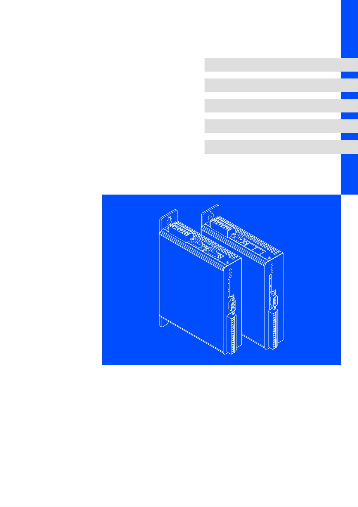
Overview
931E−002.iso
Page 4
This documentation is valid for ...
931 ... servo inverters as of nameplate data:
93 1 E x K 1 0 2.0 3.2
Product range
930
Size/power range
1 = up to 600 W
Design
E = built−in unit for IP 20 control cabinet
931E_008
Communication
C =
CAN bus integrated
P =
PROFIBUS integrated
Voltage class
K = design for low voltage
Options
1 = with digital inputs and outputs
with analog inputs and outputs
Installation
0 = installation in control cabinet
Hardware version
Software version
4
GHB 13.0001−EN EN 3.0
Page 5

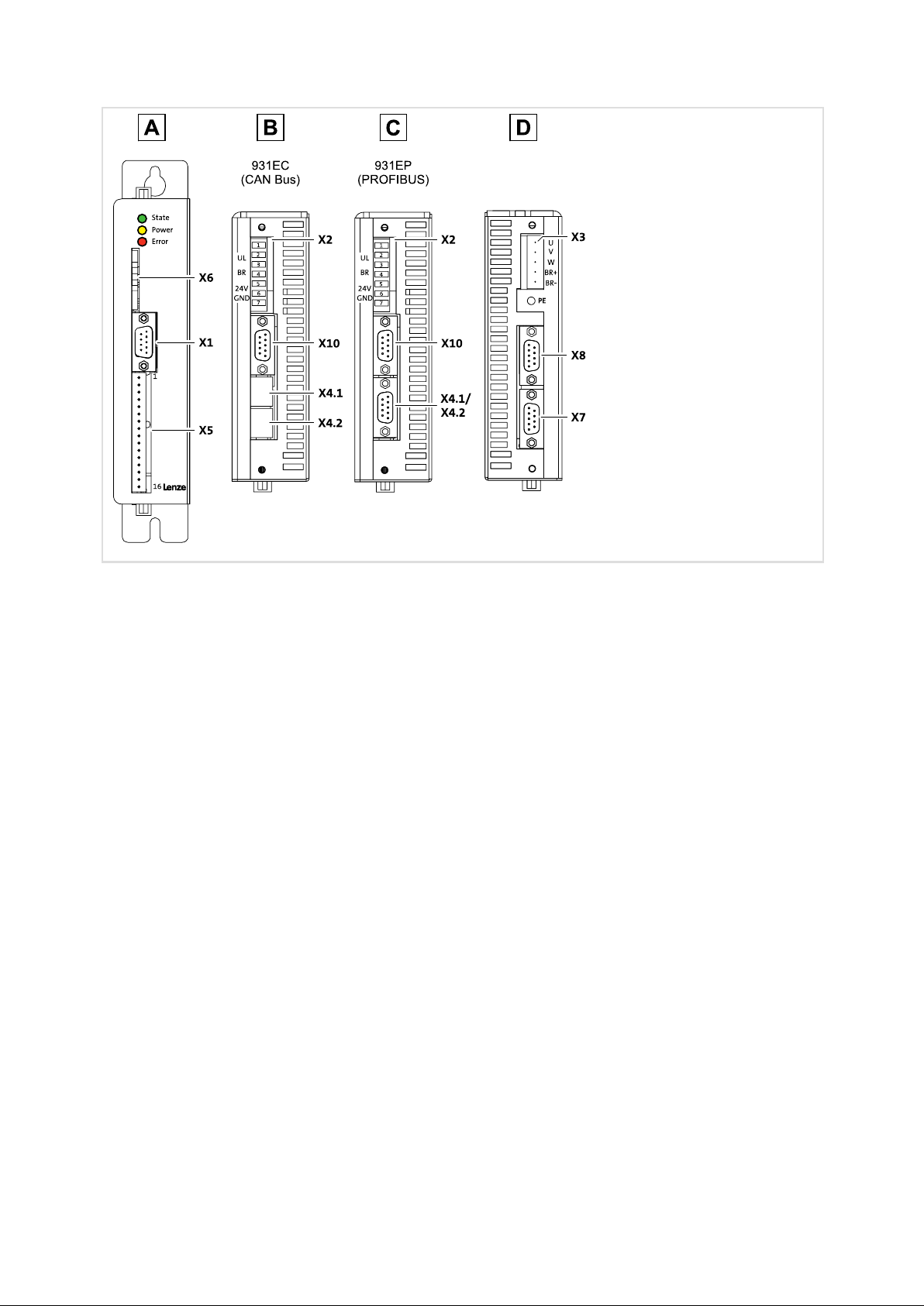
Key for the overview
View from the front
Pos. Description
X1 RS232
X5 Digital inputs and outputs / analog inputs and outputs
X6 Slot for multimedia memory card
931EC ˘ View from above
Pos. Description
X2 Voltage supply
X4.1
X4.2
X10 Digital frequency interface
931EP ˘ View from above
Pos. Description
X2 Voltage supply
X4.1/X4.2 PROFIBUS interface
X10 Digital frequency interface
View from below
Pos. Description
X3 Motor connection
X7 Resolver input
X8 SinCos encoder input
CAN interfaces
LED Colour State Note
State Green
Power Yellow
Error Red
Green
Yellow
Red
1)
Detailed description of the blink codes: 40
on The control is correctly supplied by a 24 V control voltage, the drive is ready for operation.
blinking Data is written on or read from the memory card.
off No voltage
on The power section is enabled, the motor is supplied with voltage. The drive works with the set
control.
off The drive does not work, the output stage is inactive.
off No fault
blinking Internal drive error
After the cause of the error has been eliminated, you have to acknowledge the error message:
l Either by using the parameterisation software, or via an edge at DIN9 (controller enable).
l If no error is active anymore, the LED goes out.
on l The drive is in the initialisation phase after the control voltage has been switched on.
l A new firmware is being installed.
Note!
The light−emitting diode "Error" constantly blinks if a fault is active:
ƒ It only displays one fault at a time.
ƒ If several faults are active at the same time, the fault that occured first is displayed.
1)
GHB 13.0001−EN EN 3.0
5
Page 6

What is new, what has changed ?
Material No. Version Description
.88$ 3.0 12/2007 TD35 Advanced by the 931EP (PROFIBUS) device variant
13058894 2.0 08/2005 TD09 Complete revision for the series
− 1.0 03/2003 LKA Preliminary version
0Fig. 0Tab. 0
Tip!
Current documentation and software updates concerning Lenze products can be found on
the Internet in the "Services & Downloads" area under
http://www.Lenze.com
© 2007 Lenze GmbH & Co KG Kleinantriebe, Hans−Lenze−Straße 1, D−32699 Extertal
No part of this documentation may be reproduced or made accessible to third parties without written consent by Lenze GmbH &
Co KG Kleinantriebe.
All information given in this documentation has been selected carefully and complies with the hardware and software described.
Nevertheless, discrepancies cannot be ruled out. We do not take any responsibility or liability for any damage that may occur.
Necessary corrections will be included in subsequent editions.
6
GHB 13.0001−EN EN 3.0
Page 7

Contents i
1 Preface and general information 9 . . . . . . . . . . . . . . . . . . . . . . . . . . . . . . . . . . . . . . . . . . . .
1.1 About this Manual 9 . . . . . . . . . . . . . . . . . . . . . . . . . . . . . . . . . . . . . . . . . . . . . . . . . . . .
1.2 Terminology used 9 . . . . . . . . . . . . . . . . . . . . . . . . . . . . . . . . . . . . . . . . . . . . . . . . . . . .
1.3 Scope of supply 10 . . . . . . . . . . . . . . . . . . . . . . . . . . . . . . . . . . . . . . . . . . . . . . . . . . . . . .
1.4 Legal regulations 10 . . . . . . . . . . . . . . . . . . . . . . . . . . . . . . . . . . . . . . . . . . . . . . . . . . . . .
2 Safety instructions 11 . . . . . . . . . . . . . . . . . . . . . . . . . . . . . . . . . . . . . . . . . . . . . . . . . . . . . . . . .
2.1 General safety and application notes for Lenze controllers 11 . . . . . . . . . . . . . . . . . .
2.2 Residual hazards 13 . . . . . . . . . . . . . . . . . . . . . . . . . . . . . . . . . . . . . . . . . . . . . . . . . . . . .
2.3 Definition of notes used 14 . . . . . . . . . . . . . . . . . . . . . . . . . . . . . . . . . . . . . . . . . . . . . . .
3 Technical data 15 . . . . . . . . . . . . . . . . . . . . . . . . . . . . . . . . . . . . . . . . . . . . . . . . . . . . . . . . . . . .
3.1 General data and operating conditions 15 . . . . . . . . . . . . . . . . . . . . . . . . . . . . . . . . .
3.2 Rated data 16 . . . . . . . . . . . . . . . . . . . . . . . . . . . . . . . . . . . . . . . . . . . . . . . . . . . . . . . . . .
3.3 Communication 17 . . . . . . . . . . . . . . . . . . . . . . . . . . . . . . . . . . . . . . . . . . . . . . . . . . . . . .
3.3.1 Controller with CAN bus 17 . . . . . . . . . . . . . . . . . . . . . . . . . . . . . . . . . . . . . . .
3.3.2 Controller with PROFIBUS 17 . . . . . . . . . . . . . . . . . . . . . . . . . . . . . . . . . . . . . .
4 Mechanical installation 18 . . . . . . . . . . . . . . . . . . . . . . . . . . . . . . . . . . . . . . . . . . . . . . . . . . . . .
4.1 Important notes 18 . . . . . . . . . . . . . . . . . . . . . . . . . . . . . . . . . . . . . . . . . . . . . . . . . . . . . .
4.2 Dimensions 19 . . . . . . . . . . . . . . . . . . . . . . . . . . . . . . . . . . . . . . . . . . . . . . . . . . . . . . . . . .
4.3 Mounting clearance 19 . . . . . . . . . . . . . . . . . . . . . . . . . . . . . . . . . . . . . . . . . . . . . . . . . . .
5 Electrical installation 20 . . . . . . . . . . . . . . . . . . . . . . . . . . . . . . . . . . . . . . . . . . . . . . . . . . . . . . .
5.1 Important notes 20 . . . . . . . . . . . . . . . . . . . . . . . . . . . . . . . . . . . . . . . . . . . . . . . . . . . . . .
5.2 Installation according to EMC (installation of a CE−typical drive system) 21 . . . . . . .
5.3 Voltage supply 23 . . . . . . . . . . . . . . . . . . . . . . . . . . . . . . . . . . . . . . . . . . . . . . . . . . . . . . .
5.4 Motor connection 25 . . . . . . . . . . . . . . . . . . . . . . . . . . . . . . . . . . . . . . . . . . . . . . . . . . .
5.5 Control terminals 26 . . . . . . . . . . . . . . . . . . . . . . . . . . . . . . . . . . . . . . . . . . . . . . . . . . . . .
5.6 Feedback connection 27 . . . . . . . . . . . . . . . . . . . . . . . . . . . . . . . . . . . . . . . . . . . . . . . . . .
5.6.1 Resolver at X7 27 . . . . . . . . . . . . . . . . . . . . . . . . . . . . . . . . . . . . . . . . . . . . . . . .
5.6.2 SinCos encoder at X8 28 . . . . . . . . . . . . . . . . . . . . . . . . . . . . . . . . . . . . . . . . . .
5.7 Communication 29 . . . . . . . . . . . . . . . . . . . . . . . . . . . . . . . . . . . . . . . . . . . . . . . . . . . . . .
5.7.1 Connection of digital frequency coupling at X10 29 . . . . . . . . . . . . . . . . . . .
5.7.2 Connection of CAN bus at X4.1 and X4.2 30 . . . . . . . . . . . . . . . . . . . . . . . . .
5.7.3 Connection of PROFIBUS 31 . . . . . . . . . . . . . . . . . . . . . . . . . . . . . . . . . . . . . . .
5.7.4 Connection of RS232 serial interface to X1 31 . . . . . . . . . . . . . . . . . . . . . . . .
6 Commissioning 32 . . . . . . . . . . . . . . . . . . . . . . . . . . . . . . . . . . . . . . . . . . . . . . . . . . . . . . . . . . .
6.1 Before switching on 32 . . . . . . . . . . . . . . . . . . . . . . . . . . . . . . . . . . . . . . . . . . . . . . . . . .
6.2 Initial switch−on 33 . . . . . . . . . . . . . . . . . . . . . . . . . . . . . . . . . . . . . . . . . . . . . . . . . . . . . .
GHB 13.0001−EN EN 3.0
7
Page 8

Contentsi
7 Troubleshooting and fault elimination 38 . . . . . . . . . . . . . . . . . . . . . . . . . . . . . . . . . . . . . . .
7.1 Status of the drive 38 . . . . . . . . . . . . . . . . . . . . . . . . . . . . . . . . . . . . . . . . . . . . . . . . . . . .
7.2 Error message 39 . . . . . . . . . . . . . . . . . . . . . . . . . . . . . . . . . . . . . . . . . . . . . . . . . . . . . . . .
8 Accessories 42 . . . . . . . . . . . . . . . . . . . . . . . . . . . . . . . . . . . . . . . . . . . . . . . . . . . . . . . . . . . . . . .
8.1 System cables and plugs 42 . . . . . . . . . . . . . . . . . . . . . . . . . . . . . . . . . . . . . . . . . . . . . .
8.2 Power supply units 43 . . . . . . . . . . . . . . . . . . . . . . . . . . . . . . . . . . . . . . . . . . . . . . . . . . .
8.3 Memory cards 43 . . . . . . . . . . . . . . . . . . . . . . . . . . . . . . . . . . . . . . . . . . . . . . . . . . . . . . .
8.4 Motors for 931E servo inverters 44 . . . . . . . . . . . . . . . . . . . . . . . . . . . . . . . . . . . . . . . .
8.4.1 General data and operating conditions 44 . . . . . . . . . . . . . . . . . . . . . . . . . .
8.4.2 Rated data 44 . . . . . . . . . . . . . . . . . . . . . . . . . . . . . . . . . . . . . . . . . . . . . . . . . .
8.4.3 Mechanical data 45 . . . . . . . . . . . . . . . . . . . . . . . . . . . . . . . . . . . . . . . . . . . . . .
9 Index 46 . . . . . . . . . . . . . . . . . . . . . . . . . . . . . . . . . . . . . . . . . . . . . . . . . . . . . . . . . . . . . . . . . . . .
8
GHB 13.0001−EN EN 3.0
Page 9

Preface and general information
1 Preface and general information
1.1 About this Manual
Target group
This manual addresses to all persons designing, mounting, commissioning and setting the
servo inverters of the 931 series.
Together with the catalogue, it presents the project documents for the mechanical
engineer and the system engineer.
Contents
The manual complements the mounting instructions included in the scope of supply:
ƒ The features and functions are described in detail.
ƒ It provides detailed information on the possible applications.
1
About this Manual
ƒ The parameter setting is clarified by examples.
ƒ In case of doubt, the supplied mounting instructions always apply.
Finding information
ƒ Via the contents and index, you quickly find the information regarding a specific
problem.
ƒ Descriptions and data with regard to other Lenze products can be gathered from the
respective catalogues, Operating Instructions, and Manuals.
ƒ You can request Lenze documentation from your responsible Lenze sales partner, or
download it from the Internet as a PDF file.
1.2 Terminology used
Term In the following text used for
Controller 931E servo inverter
Device 931E servo inverter
Drive 931E servo inverter with connected motor
SDC »Small Drive Control« parameterisation software
GHB 13.0001−EN EN 3.0
9
Page 10

1
Preface and general information
Scope of supply
1.3 Scope of supply
ƒ 931E servo inverter
ƒ Mounting instructions
After receipt of the delivery, check immediately whether the items delivered match the
accompanying documents. Lenze does not accept any liability for deficiencies claimed at
a later date.
Claim
ƒ visible transport damage immediately to the forwarder.
ƒ visible deficiencies / incompleteness immediately to your Lenze representative.
1.4 Legal regulations
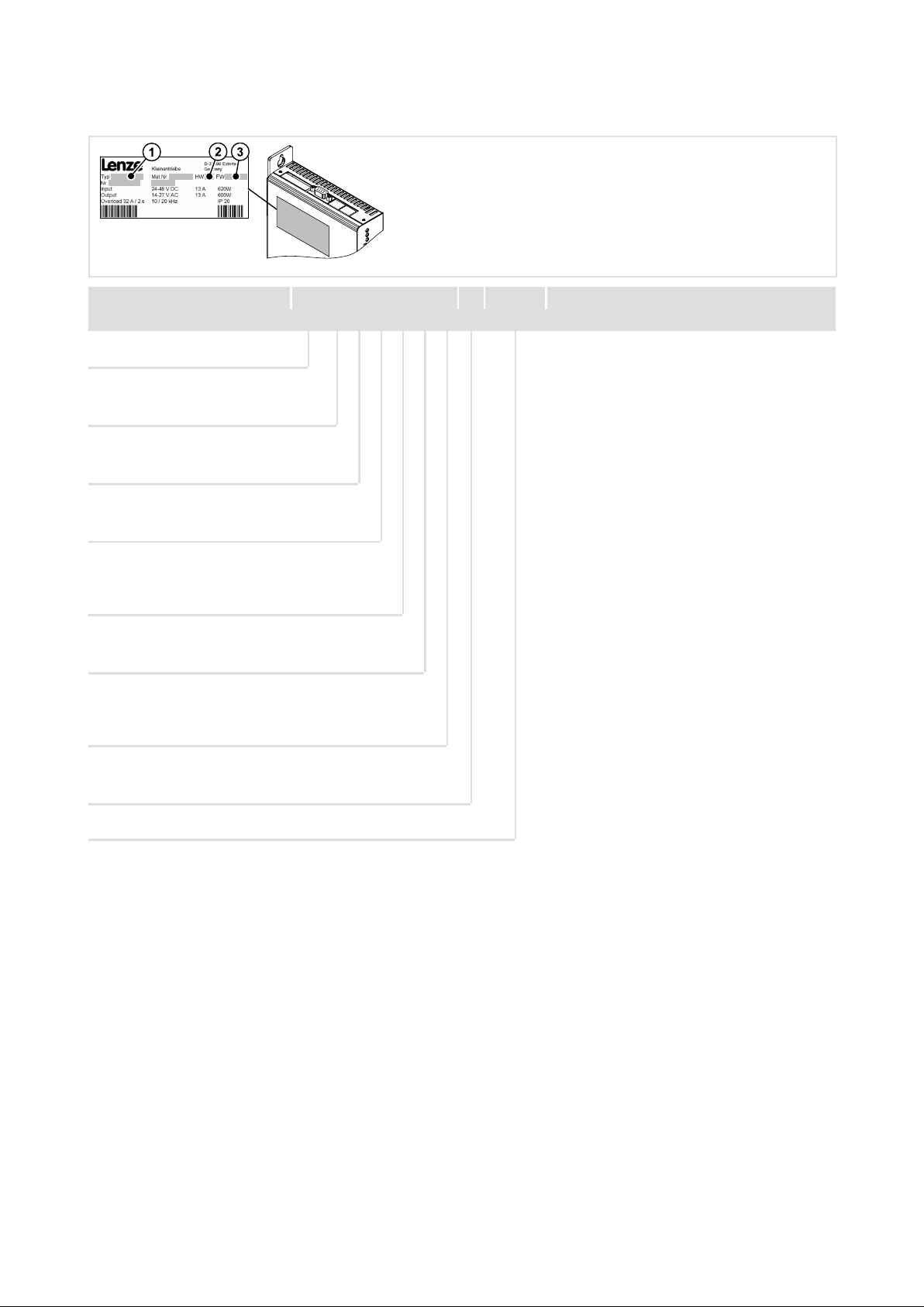
Labelling
Application as
directed
Liability l The information, data, and notes in these instructions met the state of the art at the time of printing.
Warranty l Terms of warranty: see Sales and Delivery Conditions of Lenze GmbH & Co KG Kleinantriebe.
Nameplate CE identification Manufacturer
Lenze drive controllers are
definitely identified by the
contents of the nameplate.
931E servo inverters
l must only be operated under the operating conditions prescribed in these Instructions.
l are components
– for open and closed loop control of variable speed drives with synchronous motors.
– for installation in a machine
– for assembly with other components to form a machine.
l are electric units for the installation into control cabinets or similar closed electrical operating areas.
l comply with the requirements of the Low−Voltage Directive.
l are not machines for the purpose of the Machinery Directive.
l are not to be used as domestic appliances, but only for industrial purposes.
Drive systems with 931E servo inverters
l comply with the EMC Directive if they are installed according to the guidelines of CE−typical drive systems.
l can be used
– for operation on public and non−public mains
– for operation in industrial premises.
l The user is responsible for the compliance of his application with the EC Directives.
Any other use shall be deemed as inappropriate!
Claims on modifications referring to controllers which have already been supplied cannot be derived from
the information, illustrations, and descriptions.
l The specifications, processes, and circuitry described in these Instructions are for guidance only and must
be adapted to your own specific application. Lenze does not take responsibility for the suitability of the
process and circuit proposals.
l Lenze does not accept any liability for damage and operating interference caused by:
– disregarding the Operating Instructions
– unauthorised modifications to the drive controllers
– operating errors
– improper working on and with the drive controllers
l Warranty claims must be made to Lenze immediately after detecting the deficiency or fault.
l The warranty is void in all cases where liability claims cannot be made.
In compliance with the EC
Low−Voltage Directive
Lenze GmbH & Co KG
Kleinantriebe
Postfach 10 13 52
D−31763 Hameln
10
GHB 13.0001−EN EN 3.0
Page 11

Safety instructions
General safety and application notes for Lenze controllers
2 Safety instructions
2.1 General safety and application notes for Lenze controllers
(in accordance with Low−Voltage Directive 2006/95/EC)
For your pesonal safety
During operation, Lenze controllers (frequency inverters, servo inverters, DC speed
controllers) and their corresponding components can be live, moving and rotating
according to their degree of protection. Surfaces can be hot.
Non-authorized removal of the required cover, inappropriate use, incorrect installation or
operation creates the risk of severe injury to persons or damage to material assets.
Additional information can be obtained from the documentation.
High amounts of energy are released in the controller. Thus, it is required to always wear
a personal protective equipment (body protection, headgear, eye protection, ear
protection, hand guard).
2
All operations concerning transport, installation, and commissioning as well as servicing
must be carried out by qualified, skilled personnel only (IEC 364 and CENELEC HD 384 or
DIN VDE 0100 and IEC−Report 664 or DIN VDE 0110. National regulations for the
prevention of accidents must be observed.).
According to this basic safety information, skilled personnel are persons who are familiar
with the installation, mounting, commissioning, and operation of the product and who
have the necessary qualifications for their occupation.
Application as directed
Drive controllers are components designed for the installation in electrical systems or
machinery. They must not be used as household appliances. They are intended exclusively
professional and commercial purposes according to EN 61000−3−2.
When installing the controllers into machines, commissioning (i.e. starting of operation as
directed) is prohibited until it is certain that the machine complies with the regulations of
EC Directive 98/37/EC (Machinery Directive). EN 60204 must be observed.
Commissioning (i.e. starting of operation as directed) is only allowed when there is
compliance with EMC Directive (89/336/EEC).
The controllers meet the requirements of the Low-Voltage Directive 2006/95/EC.
The technical data and information on the connection conditions can be obtained from the
nameplate and the documentation. They must be followed in any case.
Warning: Drive controllers are products with restricted availability according to
EN 61800−3. These products can cause radio interferences in residential areas. In this case,
special measures are required.
Transport, storage
Please observe the notes on transport, storage and appropriate handling.
Observe the climatic conditions according to the technical data.
GHB 13.0001−EN EN 3.0
11
Page 12

2
Safety instructions
General safety and application notes for Lenze controllers
Installation
The controllers must be installed and cooled according to the instructions given in the
corresponding documentation.
Ensure proper handling and avoid mechanical stress. Do not bend any component and do
not change any insulation distance during transport or handling. Do not touch any
electronic component or contact.
Controllers contain electrostatically sensitive components which can easily be damaged
by inappropriate handling. Do not damage or destroy any electrical component since doing
so might endanger your health!
Electrical connection
When working on live controllers, the valid regulations for the prevention of accidents (e.g.
VBG 4) must be observed.
The electrical installation must be carried out according to the appropriate regulations
(e.g. cable cross/sections, fuses, PE connection). Additional information can be obtained
from the documentation.
The documentation contains information concerning installation in compliance with EMC
(shielding, earthing, filter arrangement, and cable installation). These notes must also be
observed for CE−marked controllers. The manufacturer of the system or machine is
responsible for ensuring compliance with the limit values demanded by the EMC
legislation. The controllers must be installed in housings (e.g. control cabinets) to comply
with the limit values for radio interferences valid at the site of installation. The housings
must enable an EMC−compliant installation. Make sure in particular that e.g. the control
cabinet doors have a circumferential metal connection to the housing. Reduce housing
openings and cutouts to a minimum.
Operation
If necessary, systems including controllers must be equipped with additional monitoring
and protection devices according to the valid safety regulations (e.g. law on technical
equipment, regulations for the prevention of accidents). You are allowed to adapt the
controllers to your application. Please observe the corresponding information given in the
documentation.
After the controller has been disconnected from the voltage supply, all live components
and power connections must not be touched immediately because capacitors can still be
charged.
All protection covers and doors must be kept shut during operation.
Maintenance and servicing
The controllers do not require any maintenance if the prescribed conditions of operation
are observed.
If the ambient air is polluted, the cooling surfaces of the controller may contaminate, or the
air vents of the controller may be blocked. Therefore, the cooling surfaces and air vents
must be cleaned periodically under these operating conditions. Do not use sharp or
pointed tools for this purpose!
Waste disposal
Recycle metal and plastic materials. Assembled PCBs must be disposed of professionally.
The product−specific safety and application notes given in these instructions must be
observed!
12
GHB 13.0001−EN EN 3.0
Page 13

Safety instructions
Residual hazards
2
2.2 Residual hazards
Protection of persons
After power−off, the power terminals UL, BR and GND still carry hazardous voltages for at
least 3 minutes!
ƒ Before working on the controller, check that no voltage is applied to the power
terminals.
ƒ Always protect the power terminals against contact.
The discharge current to ground (PE) is > 3.5 mA, according to EN 50178.
ƒ If a fixed installation is required, design the PE conductor with a cable cross−section
of at least 1.5 mm
Make sure that cables are installed correctly, and that bolted connections and plug
connections are faultless.
Due to the high currents with regard to low−voltage applications, current−carrying parts
can be strongly heated.
Device protection
ƒ Connect or disconnect all pluggable terminals in a deenergised state only!
2
or use a design with double PE conductor.
ƒ A cyclic connection and disconnection of the supply voltage can overload and
destroy the input current limitation of the drive controller:
– When effecting a cyclic switching of the supply voltage over a longer period, the
period between two switch−on processes at least has to be one minute!
Motor protection
Drive systems can reach dangerous overspeeds (e.g. setting of high field frequencies for
motors and machines which are not qualified for this purpose):
ƒ The controllers do not offer any protection against these operating conditions. Use
additional components for this.
Protection of the machine/system
A missing or incorrect resolver adjustment can bring about undefined control states. The
perfect operation is no longer guaranteed.
GHB 13.0001−EN EN 3.0
13
Page 14

2
Safety instructions
Definition of notes used
2.3 Definition of notes used
The following pictographs and signal words are used in this documentation to indicate
dangers and important information:
Safety instructions
Structure of safety instructions:
Danger!
(characterises the type and severity of danger)
Note
(describes the danger and gives information about how to prevent dangerous
situations)
Pictograph and signal word Meaning
Danger!
Danger!
Stop!
Danger of personal injury through dangerous electrical voltage.
Reference to an imminent danger that may result in death or
serious personal injury if the corresponding measures are not
taken.
Danger of personal injury through a general source of danger.
Reference to an imminent danger that may result in death or
serious personal injury if the corresponding measures are not
taken.
Danger of property damage.
Reference to a possible danger that may result in property damage
if the corresponding measures are not taken.
Application notes
Pictograph and signal word Meaning
Note!
Tip!
Important note to ensure troublefree operation
Useful tip for simple handling
Reference to another documentation
14
GHB 13.0001−EN EN 3.0
Page 15

General data and operating conditions
3 Technical data
3.1 General data and operating conditions
Conformity CE 2006/95/EC Low-Voltage Directive
Regulations EN 61800−3 Interference level B
Climatic conditions Air humidity max. 90 % without condensation
Cooling Passively via housing surface and rear panel
Admissible temperature range
Transport −25 °C... +70 °C
Storage −25 °C... +70 °C
Operation 0 °C ... +50 °C above +40 °C, reduce the power by 20 W/°C
Permissible installation height 0 ... 1000 m amsl above 1000 m amsl, reduce the rated output
Mounting position Vertical
Installation clearances
above/below ³ 100 mm
sidewise Directly alignable
Monitoring Overvoltage / undervoltage in the DC bus, overcurrent or short
circuit of the output stage, motor temperature and output stage
temperature, I
Type of protection IP 20
Inputs 6 digital inputs, 2 analog inputs
(adjustable via software)
Outputs 2 digital outputs, 2 analog outputs
(adjustable via software)
Memory cards Multimedia card
Technical data
current by 5 %/1000 m
2x
t−monitoring of the motor, encoder monitoring
3
GHB 13.0001−EN EN 3.0
15
Page 16

3
Technical data
Rated data
3.2 Rated data
Supply voltage
Rated voltage 24V DC 48V DC
Permissible range 19.2 V DC − 0 % ... 57.6 V DC + 0 %
Supply current at rated power approx. 13 A
Max. supply current 35 A
Rated power 310 W 620 W
Efficiency up to 95 %
PWM frequency (switchable) 10 kHz 20 kHz 10 kHz 20 kHz
Rated output current 0 ... 13 A
Output surge current for 2 s 32 A
Rated output voltage 0 ... 14 V
Output frequency 0 ... 200 Hz
Control voltage
Control current min. 0.25 A (control section only)
Brake chopper switching threshold
On approx. 63 V DC
Off approx. 60 V DC
Overvoltage monitoring switching threshold approx. 70 V DC
Internal brake resistor
Resistance R 17 W
Permanent power P
Peak power P
External brake resistor
Resistance R > 5 W
Permanent power P
Motor holding brake 24 V / 1 A
Positioning range ± 219 revolutions
Savable positions 64
Scanning times of the control loops
Current controller 100 ms
Speed controller 200 ms
Position controller 400 ms
1)
Observe minimum voltage of the brake!
1)
pulse
eff
eff
N
N
0 ... 10 A
max. 1.5 A (all outputs connected)
eff
25 A
eff
eff
24 V DC ±20 %
200 W for 50 ms
10 ... 600 W
10 W
0 ... 13 A
32 A
eff
eff
0 ... 27 V
0 ... 10 A
25 A
eff
eff
eff
16
GHB 13.0001−EN EN 3.0
Page 17

3.3 Communication
3.3.1 Controller with CAN bus
Area Values
Communication profile DS 301, DSP 402
Communication medium RS232
Network topology Without repeater: line / with repeaters: line or tree
CAN node Slave
Baud rate (in kbps) 10, 20, 50, 100, 125, 250, 500
Maximum cable length per bus
segment
Bus connection RJ45
3.3.2 Controller with PROFIBUS
Area Values
Communication profile
(DIN 19245 part 1 and part 3)
Communication medium RS485
Drive profile PROFIdrive
Network topology Without repeater: line / with repeaters: line or tree
PROFIBUS−DP station Slave
Baud rate [kbps] 9.6 ... 12000
Maximum cable length per bus
segment
Bus connection X4.1, X4.2 9−pin Sub−D socket
Technical data
Communication
Controller with CAN bus
1200 m (dependent on baud rate and cable type used)
PROFIBUS−DP−V0
1200 m (dependent on the baud rate and cable type used)
3
GHB 13.0001−EN EN 3.0
17
Page 18

4
Mechanical installation
Important notes
4 Mechanical installation
4.1 Important notes
ƒ Use the controllers as built−in units only!
ƒ In case of contaminated cooling air (dust, lints, greases, aggressive gases):
– Take suitable preventive measures, e.g. separate air duct, installation of filters,
regular cleaning, etc.
Stop!
Do not install drives on top of each other in the control cabinet!
ƒ Observe installation clearances!
– You can install several controllers next to each other without free space in a
control cabinet.
– Ensure unimpeded ventilation of cooling air and outlet of exhaust air!
– Allow a free space of 100 mm at the top and at the bottom.
– If possible, the rear panel of the drive controller should be provided with a good
thermal connection to the control cabinet wall.
– In case of high load and a bad heat dissipation, the drive controller reduces the
drive power, or possibly switches off.
ƒ Do not exceed the range of the ambient operation temperature specified in the
Technical Data.
ƒ In case of permanent oscillation or agitation:
– Check whether shock absorbers are necessary.
Possible mounting positions:
Vertically on the control cabinet rear panel with mains terminals at the top.
18
GHB 13.0001−EN EN 3.0
Page 19

4.2 Dimensions
Mechanical installation
Dimensions
4
Fig. 1 Drive dimensions
4.3 Mounting clearance
Fig. 2 Installation clearances
931E−006.iso
931E−007.iso
GHB 13.0001−EN EN 3.0
19
Page 20

5
Electrical installation
Important notes
5 Electrical installation
5.1 Important notes
Stop!
The drive controller contains electrostatically sensitive components.
The personnel must be free of electrostatic charge when carrying out assembly
and service operations.
Danger!
ƒ The connection of all pluggable terminals has to be effected in a
deenergised state.
ƒ Connecting and disconnecting the voltage supply (X2) due to the charging
processes of the DC bus capacitor may cause traces of burning on the
plug−in connection, and may result in a destruction of the internal electronic
circuit.
ƒ A false polarity of the DC supply can bring about the destruction of the
drive. Before switching the drive on, ensure that the polarity of the
DC supply is correct.
Note!
The following requirements have to be met with regard to the trouble−free
operation:
ƒ An installation according to EMC.
ƒ The shield of the motor cable has to be applied to PE potential on a
preferably large surface in order to prevent negative effects.
ƒ The resolver cable, encoder cable, and the motor cable may have a
maximum length of 15 m!
ƒ The feeding power supply units have to be sufficiently dimensioned. The
power supply units have to be protected against overcurrent by means of
appropriate input fuses.
20
GHB 13.0001−EN EN 3.0
Page 21

Electrical installation
Installation according to EMC (installation of a CE−typical drive system)
5.2 Installation according to EMC (installation of a CE−typical drive system)
Important notes
The electromagnetic compatibility of a machine depends on the type of installation and on
the care that is taken. Special attention should be paid to:
ƒ Assembly
ƒ Shielding
ƒ Grounding
For diverging installations, the conformity to the EMC Directive requires a check of the
machine or system regarding the EMC limit values. This, for instance, applies to the use of
unshielded cables.
The compliance of the machine application with the EMC Directive is in the responsibility
of the user.
ƒ If you observe the following measures, you can assume that the machine will
operate without any EMC problems caused by the drive system, and that compliance
with the EMC Directive and the EMC law is achieved.
5
ƒ If devices which do not comply with the CE requirements concerning noise
immunity EN 50082−2 are operated close to the controller, these devices may be
electromagnetically disturbed by the controllers.
Design
Contact drive controller extensively to the grounded mounting plate:
ƒ Mounting plates with conductive surfaces (zinc−coated, stainless steel) allow
permanent contact.
ƒ Painted plates are not suitable for installation in accordance with EMC.
ƒ If you use several mounting plates, connect them extensively to one another in a
conductive manner (e. g. by using copper strips).
Shielding
ƒ Connect the shield of the motor cable on the drive controller to the shield
connection of the drive controller.
ƒ Extensively connect the shield in the terminal box on the motor or on the motor
housing to PE:
– Metal glands at the motor terminal box ensure an extensive connection of the
shield and the motor housing.
Earthing
Ground all metallically conductive components (controller, motor filter) using suitable
cables connected to a central earthing point (PE bar).
Maintain the minimum cross−sections prescribed in the safety regulations:
ƒ With regard to EMC, however, not the cable cross−section is important, but the
GHB 13.0001−EN EN 3.0
surface of the cable and the contact with a cross−section as large as possible, i.e.
large surface.
21
Page 22

5
Electrical installation
Installation according to EMC (installation of a CE−typical drive system)
Principle circuit diagram
Note!
The described terminal assignment complies with the delivery status. You can
alter the terminal assignment via the operating software.
( Software Manual 931 E)
1/PE AC 230 V
L1
N
PE
F1 F2
K10 K11
~~
==
24 ... 48 V DC
GND
24VDC
470
470
PES
560
560
S1
S2
S3
S4
S5
S6
ZZZ
PES PES
RB
1UL2UL3BR4
X2
X5
PES
1
2
3
4
5
6
7
PES
PES
8
9
10
11
12
13
14
15
16
X3
+AIN 0
-AIN 0
+AIN 1
-AIN 1
+AMON 0
+AMON 1
GND
DIN 4
DIN 5
DIN 6
DIN 7
DIN 8
DIN 9
DOUT 0
DOUT 1
DOUT 2
5
-BR
24V524V6GND7GND
931E
4
+BR
W
X4.1
X4.2
X7
X8
X10
7
1
2V3
U
PE
PE
KTY
R
M
3~
PE
22
Fig. 3 Basic circuit diagram: installation according to EMC
F1, F2 primary−side fusing of the power supply units, consider the rules of conductor protection
RB external brake resistor
PES large−surface connection of the shield to PE
minimum wiring required for operation
S1 = reversal of rotation direction
S2 = jog value selection
S3 = quick stop
S4 = limit switch 1
S5 = limit switch 2
S6 = controller enable
931E_009
GHB 13.0001−EN EN 3.0
Page 23

5.3 Voltage supply
The drive controller requires two voltage supplies on X2 for the operation:
ƒ the control voltage (24 V DC) for the supply of the internal processors as well as of
the digital outputs, and − if available − the holding brake.
ƒ the supply voltage of the power unit with 24 V or 48 V DC
Both voltages have the same reference potential in the drive controller. They are not
isolated. The connections for the control voltage and the supply voltage of the power unit
are equipped with polarity protection and are additionally secured by means of a fuse or
by a polyswitch in the drive.
Note!
In principle, it is recommended to use 2 separate DC power supply units for the
control voltage (24 V DC) and the supply voltage (24 V DC ... 48 V DC). If the
power unit is also operated with 24 V DC, you can use a common 24 V DC
power supply unit under the following conditions:
ƒ The 24 V DC power supply unit has to be highly dynamic and robust and has
to provide the required current without voltage dip even with regard to
quick changes in current (e. g. 30 A within 0.5 ms). In this respect, also the
behaviour of further loads integrated in the DC supply system has to be
taken into consideration (e. g. a further drive controller). Furthermore, the
power supply unit has to be sufficiently dimensioned with regard to the
maximum current.
ƒ With regard to longer DC supply cables, a backup capacitor has to be
switched between UL and GND, in order to stabilise the supply voltage. You
can easily check the stability of the supply voltage by means of the
oscilloscope integrated in the parameterisation software.
Electrical installation
Voltage supply
5
GHB 13.0001−EN EN 3.0
23
Page 24

5
Electrical installation
Voltage supply
Stop!
The maximum permissible current loading of the terminal strip X2 is 16 A per
terminal. If required, the supply voltage has to be connected in parallel!
X2 supply voltage
Pin No. Designation Value Specification
1
2 As 1, loop through of the supply to further drives
3 BR Connection external brake resistor against UL
4
5 As 4, loop through of the supply to further drives
6
7 As 6, loop through of the GND potential to further drives
Terminal data
Cable [mm2] [AWG] [Nm] [lb−in]
Flexible
With wire end
ferrule
UL 24 ... 48 V
24 V +24 V / 1.5 A
GND 0 V
Max. conductor cross−section Tightening torque Screw drive
7mm
DC−bus voltage output stage
Control voltage for control section, DOUT0, DOUT1, DOUT2 and holding
brake, max. 1.5 A
Common reference potential for the DC−bus voltage and control voltage
2.5 12 0.5 ... 0.6 4.4 ... 5.3 Slot 0.6 x 3.5
External brake resistors
Stop!
The drive controller does not monitor the temperature of the external resistor.
For this purpose, additional safety measures are to be considered!
The drive controller is provided with an integrated brake resistor which is designed for a
permanent power of 10 W or for a pulse power of 200 W for 50 ms.
If higher permanent or pulse powers are required, you can connect an additional external
brake resistor to the integrated brake chopper.
If the switching threshold of the brake chopper is exceeded, both resistors are energised.
Parameter Value
Switching threshold brake chopper on Approx. 63 V
Switching threshold brake chopper off Approx. 60 V
Resistance, external > 5 W
Rated power 10 W ... 600 W
24
GHB 13.0001−EN EN 3.0
Page 25

Electrical installation
Motor connection
5
5.4 Motor connection
ƒ For trouble−free operation, we recommend to use Lenze standard cables.
ƒ Ensure a proper shielding of the motor and feedback cable to avoid interferences.
X3 motor connection
Pin No. Designation Specification
1U
2 V 0 V ... 13 A
3 W 0 Hz ... 200 Hz
4 BR+
5 BR− 0 V
Terminal data
Cable [mm2] [AWG] [Nm] [lb−in]
Flexible
With wire end
ferrule
Stop!
The brake is supplied by the control voltage at X2. In order to ensure the
trouble−free operation of the brake, the control voltage has to be in the
tolerance range of the brake used!
Motor phases
Fundamental wave in case of
overload for 2 s up to 32 A
Brake
Max. conductor cross−section Tightening torque Screw drive
7mm
2.5 12 0.5 ... 0.6 4.4 ... 5.3 Slot 0.6 x 3.5
eff
approx. 0 V ... 27 V
eff
24V DC
eff
GHB 13.0001−EN EN 3.0
25
Page 26

5
Electrical installation
Control terminals
5.5 Control terminals
The digital and analog inputs and outputs are placed in the plug X5. The digital and analog
inputs and outputs have the same reference potential.
X5 inputs and outputs
Pin No. Signal
1 +AIN0 (DIN0) Analog input 0
2
3
4
5
6 +AMON1
7 GND Reference potential for pin 1 ... 6, pin 8 ... 16
8 DIN4 Digital input 4 Rated voltage +24V DC
9 DIN5 Digital input 5 Voltage range 0 ... +30 V DC
10 DIN6 Digital input 6 HIGH signal > +8 V DC
11
12 DIN8 Digital input 8 Input impedance > 4.7 kW
13 DIN9 Digital input 9
14
15
16
−AIN0 (DIN1) DIN1
+AIN1 (DIN2) Analog input 1
−AIN1 (DIN3) DIN3 Limiting frequency ~ 1 kHz
+AMON0
DIN7 Digital input 7 LOW signal < +4 V DC
DOUT0 Digital output 0
DOUT1 Digital output 1
DOUT2 Digital output 2 Switching delay
Function
Lenze Alternatively
adjustable via
SDC
DIN0
differential
(speed setpoint, current
setpoint)
DIN2
differential
Analog monitors
output of internal quantities (current, speed,
etc.)
(controller enable / delete error)
(ready for operation)
Specification
Input voltage −10 V ... +10 V
Overvoltage protection −30 V ... +30 V
Input impedance > 20 kW
Resolution
Offset error < ± 50 mV
Gain error
Output signal 0 V ... 10 V,
Switching delay
(LOW−HIGH transmission)
Output voltage 0 V / 24 V
LOW signal 0 ... 4 V DC
HIGH signal 18 V ... 30 V
Output current max. 10 mA
Load impedance
(LOW−HIGH transmission)
12 Bit
< 5 %
max. 2 mA
< 1 ms
> 2.2 kW
< 1 ms
26
Terminal data
Max. conductor cross−section Tightening torque Screw drive
Cable [mm2] [AWG] [Nm] [lb−in]
Flexible
With wire end
ferrule
7mm
2.5 12 0.5 ... 0.6 4.4 ... 5.3 Slot 0.6 x 3.5
GHB 13.0001−EN EN 3.0
Page 27

Electrical installation
Feedback connection
Resolver at X7
5
5.6 Feedback connection
5.6.1 Resolver at X7
ƒ You can connect a resolver to X7 in order to record the speed and position.
ƒ Use Lenze system cables in order to provide for a trouble−free operation.
ƒ Self−prepared cables have to be provided as follows:
– Only use cables with cores that are twisted in pairs and shielded, featuring the
specified cable cross−sections.
– Apply the shield to both sides.
Features
Features Values
Connection on the drive controller 9−pole Sub−D socket
Monitoring Monitoring of the resolver and resolver cable with regard to open
Positioning resolution 16 bit
Encoder detection resolution 12 Bit
Connectable resolvers 2−pole, U = 10 V, f = 10 kHz
Ratio 0.3 (standard) or 0.5 (as of hardware version 1.1)
Carrier frequency 8 ... 10 Nm
Permissible exciting voltage 7 V
Impedance of the excitation (at
10 kHz)
Impedance of the stator (at 10 kHz) ³ (500 + j1000) W
circuit
... 12 V
eff
eff
³ (30 + j150) W
Connection plan
<15m
X7
+REF
-REF
+COS
-COS
+SIN
-SIN
KTY
+KTY
-KTY
Fig. 4 Resolver connection
Cores twisted in pairs
Assignment of the 9−pin Sub−D socket (X7) at the controller
Pin 1 2 3 4 5 6 7 8 9
Signal +REF −REF GND +COS −COS +SIN −SIN +KTY −KTY
2
0.5 mm
(AWG 20) ˘ 0.14 mm2 (AWG 26)
1
2
3
4
5
6
7
8
9
931E−005.cdr
GHB 13.0001−EN EN 3.0
27
Page 28

5
Electrical installation
Feedback connection
SinCos encoder at X8
5.6.2 SinCos encoder at X8
ƒ You can connect a SinCos encoder with serial communication (single turn or multi
turn) to X8.
ƒ Use Lenze system cables in order to provide for a trouble−free operation.
ƒ Self−prepared cables have to be provided as follows:
– Only use cables with cores that are twisted in pairs and shielded, featuring the
specified cable cross−sections.
– Apply the shield to both sides.
Features
Field Values
Connection on the drive controller 9−pole Sub−D socket
Input frequency: Max. 100 kHz
Current consumption per channel: 6 mA
Supply of the incremental encoder l Via X8/4 (VCC, DC 5 V), X8/5 (GND)
Encoder with number of increments 128 − 1024 periods / revolution
Angular resolution l Interpolation min. 10 Bit
Recommended encoders Sick−Stegmann SKS / SKM36
l Max. current consumption at X8/4: 200 mA
l Speed measurement 20 Bit
l Positioning 16 Bit
l Angular error < 2’
Connection plan
<15m
B
B
A
A
V
CC
GND
Z
KTY
Z
+KTY
-KTY
Fig. 5 Connection of incremental encoder with TTL level
Signals for CW rotation
Cores twisted in pairs
Assignment of 9−pin Sub−D socket (X8) at the controller
Pin 1
2 3 4 5 6 7 8 9
Signal B A A V
2
0.14 mm
(AWG 26) 1 mm
X8
1
2
3
4
A
5
A
6
B
7
B
8
Z
Z
9
GND (−KTY) Z Z +KTY B
CC
2
(AWG 18) 0.14 mm
2
(AWG 26)
931E−004.cdr
28
GHB 13.0001−EN EN 3.0
Page 29

Connection of digital frequency coupling at X10
5.7 Communication
ƒ In order to provide for a perfect operation, we recommend the use of Lenze system
cables. ( 42)
ƒ Check the plug connections of the bus cables with regard to a tight fit.
5.7.1 Connection of digital frequency coupling at X10
ƒ Master frequency features:
– Angular resolution / number of increments max. 12 bits / 1024 increments
switchable to 512 / 256 / 128 / 64 and 32 increments
– Track signals A, B, Z in accordance with RS422 standard
– Output impedance R
Output X10 Input X10
l Output frequency: 0 ... 500 kHz
l Current capacity per channel: max 20mA.
l Two−track with inverse 5 V signals (RS422) and zero
track
l In case of a parallel connection maximally three
slave drives can be connected
l By LOW level, PIN 8 (enable) indicates the
initialisation of the master drive (e. g. when the
mains has been switched off in the meantime). This
enables the slave drive to monitor the master.
= 120 W
a,diff
Technical data master frequency
l Input frequency:
l Max. 5 mA
l Two−track with inverse signals and zero track
Electrical installation
Communication
– 0 ... 500 kHz for TTL level
– With regard to incremental encoders with HTL
level, also operable without reversed signals
5
Connection plan
<15m
X10 X10
AA
1
BB
2
ZZ
3
GND GND
4
5
A
6
B B
7
8
Z Z
GND GND
9
Fig. 6 Connection of digital frequency input and digital frequency output (X10)
X10 Slave drive Signals with CW rotation
X10 Master drive
Assignment of 9−pin Sub−D socket (X10) at the controller for digital frequency coupling
Pin 1 2 3 4 5 6 7 8 9
Signal A B Z GND n. c. A B Z GND
0.14 mm
(AWG 26)
1
2
3
4
5
A
6
7
8
9
A
A
B
B
Z
Z
931E−003.cdr
Cores twisted in pairs
2
0.5 mm
(AWG 20)
2
0.14 mm
(AWG 26)
2
0.5 mm
(AWG 20)
2
0.14 mm
(AWG 26)
2
GHB 13.0001−EN EN 3.0
29
Page 30

5
Electrical installation
Communication
Connection of CAN bus at X4.1 and X4.2
5.7.2 Connection of CAN bus at X4.1 and X4.2
Features
ƒ Parameter presettings
ƒ Data exchange from controller to controller
ƒ Connection of operator and input devices
ƒ Connection of external controls and control systems
ƒ Baud rate 125, 250, 500 kBaud
Stop!
For the termination of the bus system, an external 120 W terminating resistor is
required.
Connection plan
X4.1 / X4.2
Fig. 7 Connection of CAN bus (X4.1, X4.2)
Pin no. Meaning Comment
1 CAN−HIGH CAN−HIGH (high is dominant)
2 CAN−LOW CAN−LOW (low is dominant)
3 CAN−GND CAN ground
4 Reserved
5 Reserved
6 CAN−SHLD CAN shield (hardware version 1.1 and higher)
7 CAN−GND CAN ground
8 Reserved
Tip!
An RJ45 bus terminating connector is available for the 931E drive controllers.
Please contact Lenze.
931E−001.iso
30
GHB 13.0001−EN EN 3.0
Page 31

Electrical installation
Communication
Connection of PROFIBUS
5
5.7.3 Connection of PROFIBUS
Assignment of Sub−D socket
The controller is connected to the PROFIBUS via the 9−pin Sub−D socket X4.1/X4.2.
View Pin Designation Explanation
1 − −
2 − −
9
6
5
1
3 RxD/TxD−P Data line B (received/transmitted data plus)
4 RTS Request to send
(received/transmitted data, no differential signal)
5 M5V2 Data reference potential (ground to 5V)
6 P5V2 5 V DC / 30 mA (bus termination)
7 − −
8 RxD/TxD−N Data line A (received/transmitted data minus)
9 − −
5.7.4 Connection of RS232 serial interface to X1
The serial interface is designed as a 9−pole Sub−D−plug. The signal levels comply with the
RS232 specification.
X1 RS232
Pin No. Designation Value
1 n. c. Not assigned
2 R x D 0 V / 10 V
3 T x D 0 V / 10 V
4 n. c. Not assigned
5 GND
6
7
8
9
n. c. Not assigned
GHB 13.0001−EN EN 3.0
31
Page 32

6
Commissioning
Before switching on
6 Commissioning
6.1 Before switching on
Stop!
Avoid injury to persons and damage to material assets during commissioning!
ƒ Necessarily observe the switch−on sequence.
ƒ During the resolver adjustment, the drive has to be able to rotate freely
without load!
Tip!
For faults during commissioning, see chapter Troubleshooting and fault
elimination. ( 38)
Before the first commissioning and before commissioning after longer downtimes, check:
Check Checked
Have all necessary electrical connections been established?
Are there no short circuits and earth faults?
Are all plug connections fixed?
Are all plugs secured with the bolted connections specified for this purpose?
Are all bolted connections tightened?
Are control voltage and power supply connected with the right polarity?
Are the output voltages of the power supply units set correctly?
+24 V DC for the control
+24V DC or +48 V DC for the power supply
Is the shield of the motor cable and that of the feedback cable correctly applied?
Are the correct signals assigned to the digital inputs and outputs?
Are at least DIN9 (controller enable), DIN6 (start positioning) assigned?
If limit switches are connected, are they connected to DIN7 and DIN8?
If you use the analog inputs for the setpoint selection or for torque limitation
Are the correct signals assigned to the analog inputs?
Is the voltage for the analog inputs settled in the permissible range
0 ... 10 V?
32
GHB 13.0001−EN EN 3.0
Page 33

6.2 Initial switch−on
Note!
The described terminal assignment complies with the delivery status. You can
alter the terminal assignment via the operating software.
( Software Manual 931 E)
Tip!
The windows to the individual menu items in the »Small Drive Control (SDC)«
parameterisation software remain open after you have entered and adopted
changes.
Close the windows when you have edited a menu item, so that the monitor
operations remain clearly visible.
Commissioning
Initial switch−on
6
When carrying out initial commissioning, some basic settings have to be effected before
the drive can be started.
GHB 13.0001−EN EN 3.0
33
Page 34

6
Commissioning
Initial switch−on
Basic settings:
1. Connect the serial interface on the drive controller and on the PC to a null modem
cable.
2. Switch on the control voltage, but not yet the power supply!
– If the green LED (state) is blinking, the voltage is in the permissible range.
3. Start the »Small Drive Control (SDC)« parameterisation software.
– If you are not able to effect a connection between the PC and the drive controller,
check the setting of the serial interface on the PC (see Software Manual).
– If communication is defective, a message is displayed on the user interface.
4. Select the item "Select as commissioned" in the window "Initial commissioning".
– Ignore the error messages which are displayed due to the power supply that is not
yet existent.
5. Select the connected motor in the "Parameters Drive parameters Motor data"
menu.
– If you select a motor from the integrated motor data base, you do not have to
enter the motor parameters manually.
– If you do not find the connected motor in the motor data base, you have to enter
the motor parameters manually. The data can be gathered from the nameplate of
the motor.
6. Select and parameterise the connected encoder system in the "Parameters Drive
parameters Resolver settings" menu.
7. Select the operating mode "Speed control" in the window "Commands".
8. Assign the setpoint sources in the "Operating mode Setpoint selection..." menu:
– analog speed setpoint (±10 V DC) via AIN0
931E_013
34
GHB 13.0001−EN EN 3.0
Page 35

Commissioning
Initial switch−on
9. Parameterise the analog terminals in the "Parameters I/Os... Analog inputs"
menu:
– Here you assign the setpoint quantity to the voltage level.
– By means of the offset, you can adjust the potentiometer.
– By means of the slide control "safe null", you can define a range where the motor
is safely stopped.
6
931E_012
GHB 13.0001−EN EN 3.0
35
Page 36

6
Commissioning
Initial switch−on
10. Parameterise the digital terminals in the "Parameters I/Os... Digital inputs"
menu.
– Terminal assignment see connection example. ( 22)
– The analog inputs may not be configured as digital inputs. Therefore, in the
"Parameters IOs Digital inputs" menu, check whether the selection
"Interprete AINs as DINs" is not set! Otherwise you are not able to evaluate the
analog setpoint.
– The function of the digital inputs can be displayed under the menu item "Function
overview". Check the right function here.
– The 931E Software Manual decribes how you configure analog inputs as digital
inputs.
11. Set the threshold for the undervoltage recognition in the "Parameters Drive
parameters DC bus monitoring" menu.
– Adjust the threshold according to the application and the supply voltage (e. g. 16 V
for 24 V DC power supply).
The basic settings are now completed.
Now you calibrate the feedback system and the controller parameters.
931E_011
36
GHB 13.0001−EN EN 3.0
Page 37

Commissioning
Initial switch−on
Calibrating the feedback system and the controller parameters:
12. Make sure that the controller is inhibited!
– DIN9 = LOW
13. Switch on the power supply.
14. Check whether error messages are pending.
– First of all, eliminate and acknowledge the errors, or alter the error tracking
system.
15. Make sure that the drive can rotate without load!
16. Select the resolver adjustment in the "Parameters Drive parameters Resolver
settings" menu.
– Caution: the motor shaft rotates during the adjustment!
17. Parameterise the controller in the "Parameters Controller parameters Speed
controller menu.
6
Note!
If you have selected a Lenze servo motor from the motor data base, the current
controller parameters are already optimised.
If required, the parameters have to be slightly adapted to your application.
18. Use the icon "Save parameters" in the menu bar, in order to save the settings in the
EEPROM of the drive controller in a powerfail−proof manner.
The settings are completed.
You can now start the drive.
Starting the drive:
19. Set a speed setpoint on AIN0.
20. Enable controller.
– DIN9 = HIGH
21. The drive now operates in speed−controlled operation.
22. If you want to change the direction of rotation during operation:
– Change in potential on AIN0
– HIGH signal on DIN4
Detailed information can be found in the 931E Software Manual.
GHB 13.0001−EN EN 3.0
37
Page 38

7
Troubleshooting and fault elimination
Status of the drive
7 Troubleshooting and fault elimination
7.1 Status of the drive
The current operating status of the drive controller is displayed by 3 light−emitting diodes.
Thus, a quick diagnostics is possible. Details with regard to diagnostics information are
supplied by the parameterisation software.
LED Colour State Note
State Green
Power Yellow
Error Red
Green
Yellow
Red
on The control is correctly supplied by a 24 V control voltage, the drive is ready for operation.
blinking Data is written on or read from the memory card.
off No voltage
on The power section is enabled, the motor is supplied with voltage. The drive works with the set
off The drive does not work, the output stage is inactive.
off No fault
blinking Internal drive error
on l The drive is in the initialisation phase after the control voltage has been switched on.
1)
Detailed description of the blink codes: 40
control.
1)
After the cause of the error has been eliminated, you have to acknowledge the error message:
l Either by using the parameterisation software, or via an edge at DIN9 (controller enable).
l If no error is active anymore, the LED goes out.
l A new firmware is being installed.
Note!
The light−emitting diode "Error" constantly blinks if a fault is active:
ƒ It only displays one fault at a time.
ƒ If several faults are active at the same time, the fault that occured first is
displayed.
38
GHB 13.0001−EN EN 3.0
Page 39

7.2 Error message
Various monitoring functions protect the drive against impermissible operating
conditions. If a monitoring function is activated, a response corresponding to the
protection of the drive is actuated. The following things are monitored:
ƒ Temperature of the output stage
ƒ Motor temperature
ƒ I2t monitoring of the motor
ƒ Overcurrent / short circuit of the output stage
ƒ DC−bus voltage (under− and overvoltage)
ƒ Following error with regard to position control
ƒ Error with regard to the reference run
ƒ Error with regard to the angle encoder system
Troubleshooting and fault elimination
Error message
7
ƒ Communication error
ƒ Initialisation error
ƒ Check sum error of the parameters
Some responses to failures can be set within the SDC parameterisation software. Possible
responses are:
Reaction Meaning Reaction of the drive
A Immediate disconnection of the
output stage
h Emergency stop The motor is braked to zero speed at the current limit. If there
W Warning The controller keeps operating, the output stage remains
O Off The warning signal is inhibited − no response.
The motor coasts.
is a motor holding brake, it is applied. The output stage
switches off.
switched on. The warning signal can be read out via the CAN
bus or via the serial RS232 interface.
Used symbols:
Symbol Meaning
þ Default setting
¨ Response parameterisable in SDC
− Selection not possible
GHB 13.0001−EN EN 3.0
39
Page 40

7
Troubleshooting and fault elimination
Error message
Red LED is
blinking
15x þ − − − Parameter set
10x þ ¨ ¨ ¨ I2t error l Adjust the i2t time of the motor.
9x þ ¨ ¨ ¨ Following error position
8x þ − − − Resolver or SINCOS
7x þ − − − Overvoltage in the DC
Reaction
A h W O
Cause Remedy
inconsistent
control
encoder error; as the case
may be, definite
recognition only possible
after approx. ½ motor
revolution
bus > 70 V
Check parameter set of the drive by means
of the parameterisation software ( 931E
Software Manual).
( 931E Software Manual)
l Effect resolver adjustment. ( 931E
Software Manual)
l Check set motor data. ( 931E
Software Manual)
l Optimise controller setting. ( 931E
Software Manual)
l Adjust travel profile (e. g. adjust
acceleration ramps).
l Reduce load torque of the motor.
l Optimise controller setting to improve
the running precision. ( 931E
Software Manual)
l Adjust travel pofile (e. g. reduce
acceleration and braking ramps.
( 931E Software Manual)
l Amplify following error
window/increase switch−in delay.
( 931E Software Manual)
l Check correct fit of the resolver plug.
l Check resolver cable with regard to
cable breakage, short circuit.
l Check PIN assignment of the resolver
cable plug.
l Parameterise encoder correctly.
( 931E Software Manual)
l Check whether power supply unit
operates correctly, and whether the
supply voltage of the power unit is
settled in the permissible range
(19.2 V DC ... 57.6 V DC).
l Decrease the steepness of the braking
ramp. (931E Software Manual)
l Connect external brake resistor to X2.
l Check whether other drives connected
to the DC supply of the power unit have
caused this overvoltage.
40
GHB 13.0001−EN EN 3.0
Page 41

Troubleshooting and fault elimination
Error message
RemedyCauseReactionRed LED is
Red LED is
blinking
blinking
6x þ − − − Overcurrent / short
5x þ − − − System error Switch off and then reconnect control
4x þ ¨ − − Overtemperature drive
3x þ ¨ ¨ ¨ Overtemperature motor l Check whether the motor cooling via
2x þ ¨ ¨ ¨ Undervoltage in the DC
1x ¨ ¨ þ ¨ MMC not connected l Check setting of multimedia card
OWhA
circuit
controller
bus
RemedyCause
Check motor cable and motor phases with
regard to a short circuit of the phases or
the drive
voltage. If the error re−occurs, send in the
drive.
l Check correct mounting in the control
cabinet:
– Heatsink has to fit extensively to the
housing of the control cabinet.
– Are further heat sources mounted
near the drive controller, bringing
about an increased ambient
temperature of the inverter?
l Check whether the ventilation slots of
the drive controller are soiled or
blocked. If required, clean.
l Optimise controller settings (bad
settings result in an unnecessary
heating). ( 931E Software Manual)
l Check resolver adjustment. ( 931E
Software Manual)
l Reduce load torque of the motor.
the motor housing is prevented by
deposits, etc.(if required, cleaning of the
motor).
l Are there further heat sources near the
motor, bringing about an additional
increase in the predominant ambient
temperature, and thus contributing to a
diminution of the dissipation of lost
heat?
l Check controller settings, bad settings
result in an unnecessary heating.
( 931E Software Manual)
l Reduce load torque of the motor.
l Check setting of the thermal sensor.
l Check resolver cable or encoder cable
with regard to open circuit.
l Check resolver adjustment. ( 931E
Software Manual)
l Check DC−bus voltage, if required,
adjust undervoltage trigger level.
( 931E Software Manual)
(MMC).
l Connect MMC.
l Change setting of the error tracking
system by means of the
parameterisation software.
7
GHB 13.0001−EN EN 3.0
41
Page 42

8
Accessories
System cables and plugs
8 Accessories
8.1 System cables and plugs
Connector plugs
Set connector plugs Use Rated current /
X3 Motor connection 16 A / 2.5 mm
x2 Voltage supply 16 A / 2.5 mm
X5 Inputs and outputs 1 A / 1.5 mm
max. cross−section
Motor connection system cables
Motor − servo inverter
Connection on the servo
inverter
X3 (U, V, W, PE)
Resolver feedback
Connection on the servo
inverter
X7
Sub−D plug, 9−pole
Absolute value encoder feedback
Connection on the servo
inverter
X8
Sub−D socket, 9−pole
Length [m] Connection on the motor Order number
2.5
5
Length [m] Connection on the motor Order number
2.5
5 13011242
Length [m] Motor connection side Order number
2.5
5 13041363
6−pole socket
M23 socket, 12−pole
M23 socket, 12−pole
Order number
2
2
2
13041955
13009636
13011101
13009635
13041367
42
Communication system cables
CAN system cable
CAN input Length [m] CAN output Order number
X4.1
RJ 45 plug
Serial null modem connection RS232
Connection on the servo
inverter
x1
Sub−D socket, 9−pole
3 X4.2
RJ 45 plug
Length [m] Connection on the PC Order number
1.8 Sub−D socket, 9−pole 492232
492234
GHB 13.0001−EN EN 3.0
Page 43

8.2 Power supply units
Technical data of the power supply units
Secondary side Primary side Order number
DC 24 V
(DC 2.5 ... 28.5 V)
DC 24 V
(DC 2.5 ... 28.5 V)
DC 48 V
(DC 40 ... 56 V)
5A
10 A Approx. 2.34 A (AC 120 V)
20 A Approx. 4.76 A (AC 120 V)
5A
10 A Approx. 3 × 0.63 A
20 A Approx. 3 × 1.1 A
5A AC 85 V − 0 % ... 264 V + 0 %
10 A
20 A Approx. 3 × 2.3 A
AC 85 V − 0 % ... 264 V + 0 %
45 Hz − 0 % ... 65 Hz + 0 %
3 AC 320 V − 0 % ... 575 V + 0 %
45 Hz − 0 % ... 65 Hz + 0 %
45 Hz − 0 % ... 65 Hz + 0 %
3 AC 320 V − 0 % ... 575 V + 0 %
45 Hz − 0 % ... 65 Hz + 0 %
Accessories
Power supply units
Approx. 1.6 A (AC 120 V)
Approx. 0.84 A (AC 230 V)
Approx. 1.2 A (AC 230 V)
Approx. 2.3 A (AC 230 V)
Approx. 3 × 0.36 A
(AC 400 V)
Approx. 3 × 0.34 A
(AC 480 V)
(AC 400 V)
Approx. 3 × 0.57 A
(AC 480 V)
(AC 400 V)
Approx. 3 × 1.0 A
(AC 480 V)
Approx. 2.2 A (AC 120 V)
Approx. 1.2 A (AC 230 V)
Approx. 3 × 1.2 A
(AC 400 V)
Approx. 3 × 1.0 A
(AC 480 V)
(AC 400 V)
Approx. 3 × 1.9 A
(AC 480 V)
8
EZV1200−000
EZV2400−000
EZV4800−000
EZV1200−001
EZV2400−001
EZV4800−001
EZV2400−002
EZV4800−002
EZV9600−000
8.3 Memory cards
Memory cards (on request)
Format Capacity Order number
MMC (multimedia card) 64 MB 13041516
GHB 13.0001−EN EN 3.0
43
Page 44

8
Accessories
Motors for 931E servo inverters
General data and operating conditions
8.4 Motors for 931E servo inverters
Further information on motors and gearboxes can be gathered from the
respective catalogue.
8.4.1 General data and operating conditions
Design Smooth, round
Design B14 flange in accordance with DIN 42948 and IEC 72; form C
Cooling Naturally ventilated
Insulation material class F
Winding insulation Max. voltage amplitude 1500 V; du/dt < 5 kV/ms
Permissible temperature ranges
Operation −20 °C ... + 40 °C
Type of protection IP54 in accordance with DIN EN60034−5
Connection System connector
Temperature monitoring KTY 110
Speed feedback Pancake resolver (size 15)
Absolute value encoder
8.4.2 Rated data
Motor type
SDSGS 035−22 SDSGS 035−22 SDSGS 047−22
Rated power [W] 140 140 210
Rated torque [Nm] 0.45 0.45 0.8
Rated current [A] 9.5 4.0 6.2
Rated voltage [V] 13 30 30
Rated frequency [Hz] 100 100 83
Rated speed [min−1] 3000 3000 2500
Power factor 1 1 1
Maximum speed, mechanical [min−1] 6000 6000 6000
Continuous standstill torque [Nm] 0.55 0.55 1
Continuous standstill current [A] 10.4 4.4 6.7
Maximum continuous standstill torque for 2 s [Nm] 1.0 2.9 4/5
Operating mode S1 S1 S1
Moment of inertia [kgcm2] 0.293 0.293 0.444
44
GHB 13.0001−EN EN 3.0
Page 45

Accessories
Motors for 931E servo inverters
Mechanical data
8.4.3 Mechanical data
Motor type
SDSGS 035−22 SDSGS 035−22 SDSGS 047−22
Weight [kg] 2.2 2.2 3
Flange IEC IEC56 B14 C80 IEC56 B14 C80 IEC56 B14 C80
Shaft end IEC 72 9 x 20 9 x 20 11 x 20
Locating bearing at the output end 6000 6000 6000
Floating bearing 6000 6000 6000
Max. radial force Fr top of pivot
Max. radial force Fr middle of pivot
Max. axial force F
*)
a
*)
Forces determined for bearing service−life of 20000h
*)
*)
[N] 250 250 300
[N] 260 260 350
[N] 200 200 250
Fr
8
Fa
l/2
l
Fig. 8 Points of application of the radial (Fr) and axial force (Fa)
GHB 13.0001−EN EN 3.0
45
Page 46

Index9
9 Index
A
Application as directed, 10
B
Baud rate, 17
C
Cable length, per bus segment, 17
Commissioning, 32
− Initial switch−on, 33
Communication profile, 17
Connection incremental encoder, at X8, 28
Connection plan, 27 , 28 , 29 , 30
Control terminals, 26
Controller
− Application as directed, 10
− Labelling, 10
D
Definition of notes used, 14
Definitions, 9
Device protection, 13
Drive profile, 17
Liability, 10
M
Manufacturer, 10
Mechanical installation, 18
Motor protection, 13
Mounting clearance, 19
N
Nameplate, 4
Network topology, 17
Notes, definition, 14
O
Operating conditions, 44
Overspeeds, 13
P
PROFIBUS, 31
PROFIBUS−DP function module,
communication medium, 17
Protection of persons, 13
E
E82ZAFPC00x, baud rate, 17
Electrical installation, 20
Error message, 39
G
General data, 44
I
Incremental encoder, connection at X8, 28
Initial switch−on, 33
Installation, PROFIBUS, 31
Installation, electrical, 20
Installation, mechanical, 18
L
Labelling, controller, 10
Legal regulations, 10
R
Rated data, 44 , 45
Residual hazards, 13
Resolver, Connecting, 27
S
Safety instructions, 11
− Definition, 14
− Structure, 14
Switch on, initial, 33
T
Technical data, 15
Troubleshooting and fault elimination, 38
Type code, 4
W
Warranty, 10
Waste disposal, 12
46
GHB 13.0001−EN EN 3.0
Page 47

Lenze GmbH & Co KG Kleinantriebe
Hans−Lenze−Straße 1
D−32699 Extertal
Germany
(
( Service
Ê Service
E−Mail Lenze@Lenze.de
Internet www.Lenze.com
+49(0)515482−0
0080002446877 (24 h helpline)
+49(0)515482−1112
GHB 13.0001−EN
EN 3.0
© 12/2007
TD35
10987654321
 Loading...