

Page 1
EDS84DPNET
13358511
Ä.Dv,ä
L-force Communication
Communication Manual
8400 protec
E84DxxxxxxxxxR
PROFINET
L
Page 2

2 L EDS84DPNET EN 4.0 - 11/2010
Page 3

Communication manual 8400 protec PROFINET
Contents
Contents
1 About this documentation . . . . . . . . . . . . . . . . . . . . . . . . . . . . . . . . . . . . . . . . . . . . . . . . . . . . . . . . . 5
1.1 Document history
1.2 Conventions used
1.3 Terminology used
1.4 Notes used
2 General information
3 Technical data
3.1 General data and operating conditions of the PROFINET
3.2 Protocol data
3.3 Communication time
3.4 Internal switch latency
4 Installation
4.1 Network topology
4.2 PROFINET connection
4.2.1 PROFINET connection via the RJ45 socket
4.2.2 PROFINET connection via the M12 socket
5 Commissioning
. . . . . . . . . . . . . . . . . . . . . . . . . . . . . . . . . . . . . . . . . . . . . . . . . . . . . . . . . . . . . . . . . . . . . . 10
. . . . . . . . . . . . . . . . . . . . . . . . . . . . . . . . . . . . . . . . . . . . . . . . . . . . . . . . . . . . . . . . . . . . 13
. . . . . . . . . . . . . . . . . . . . . . . . . . . . . . . . . . . . . . . . . . . . . . . . . . . . . . . . . . . . . . . . . . . . . . . 16
. . . . . . . . . . . . . . . . . . . . . . . . . . . . . . . . . . . . . . . . . . . . . . . . . . . . . . . . . . . . . . . . . . . 23
. . . . . . . . . . . . . . . . . . . . . . . . . . . . . . . . . . . . . . . . . . . . . . . . . . . . . . . . . . . . . . . 7
. . . . . . . . . . . . . . . . . . . . . . . . . . . . . . . . . . . . . . . . . . . . . . . . . . . . . . . . . . . . . . . 8
. . . . . . . . . . . . . . . . . . . . . . . . . . . . . . . . . . . . . . . . . . . . . . . . . . . . . . . . . . . . . . . 9
. . . . . . . . . . . . . . . . . . . . . . . . . . . . . . . . . . . . . . . . . . . . . . . . . . . . . . . . . . . . . . . 11
. . . . . . . . . . . . . . . . . . . . . . . . . . . . . . . . . . . . . . . . . . . . . . . . . . . . . . . . . . . . . . . . . . . 13
. . . . . . . . . . . . . . . . . . . . . . . . . . . . . . . . . . . . . . . . . . . . . . . . . . . . . . . . . . . . 14
. . . . . . . . . . . . . . . . . . . . . . . . . . . . . . . . . . . . . . . . . . . . . . . . . . . . . . . . . . 15
. . . . . . . . . . . . . . . . . . . . . . . . . . . . . . . . . . . . . . . . . . . . . . . . . . . . . . . . . . . . . . . 16
. . . . . . . . . . . . . . . . . . . . . . . . . . . . . . . . . . . . . . . . . . . . . . . . . . . . . . . . . . . . 18
. . . . . . . . . . . . . . . . . . . . . . . . . . . 13
. . . . . . . . . . . . . . . . . . . . . . . . . . . . . . . . . 19
. . . . . . . . . . . . . . . . . . . . . . . . . . . . . . . . . 22
5.1 Before initial switch-on
5.2 Configuring the PROFINET IO controller
5.3 Setting the station name
5.4 Setting the IP configuration
5.5 Initial switch-on
6 Data transfer
7 Process data transfer
7.1 Accessing process data / PDO mapping
7.2 Preconfigured port interconnection of the process data objects (PDO)
7.3 Freely configuring the port interconnection of the process data objects (PDO)
. . . . . . . . . . . . . . . . . . . . . . . . . . . . . . . . . . . . . . . . . . . . . . . . . . . . . . . . . . . . . . . . . . . . . 30
. . . . . . . . . . . . . . . . . . . . . . . . . . . . . . . . . . . . . . . . . . . . . . . . . . . . . . . . . . . . . . . . . 29
. . . . . . . . . . . . . . . . . . . . . . . . . . . . . . . . . . . . . . . . . . . . . . . . . . . . . . . . . . . . . . 31
. . . . . . . . . . . . . . . . . . . . . . . . . . . . . . . . . . . . . . . . . . . . . . . . . . . . . . . . . . 23
. . . . . . . . . . . . . . . . . . . . . . . . . . . . . . . . . . . . . . . . . . 24
. . . . . . . . . . . . . . . . . . . . . . . . . . . . . . . . . . . . . . . . . . . . . . . . . . . . . . . . 25
. . . . . . . . . . . . . . . . . . . . . . . . . . . . . . . . . . . . . . . . . . . . . . . . . . . . . . 27
. . . . . . . . . . . . . . . . . . . . . . . . . . . . . . . . . . . . . . . . . . . 31
. . . . . . . . . . . . . . 32
. . . . . . 33
EDS84DPNET EN 4.0 - 11/2010 L 3
Page 4

Communication manual 8400 protec PROFINET
Contents
8 Parameter data transfer . . . . . . . . . . . . . . . . . . . . . . . . . . . . . . . . . . . . . . . . . . . . . . . . . . . . . . . . . . . 37
8.1 The acyclic channel (PROFIdrive profile)
8.1.1 Connection establishment of an IO controller to an IO device
8.1.2 Acyclic data transmission process
8.1.3 Structure of the PROFINET data telegram
8.2 Reading parameters from the controller
8.2.1 Response after a correct read request
8.2.2 Response after a read error
8.2.3 Telegram example: Read request
8.3 Writing parameters to the controller
8.3.1 Response after a correct write request
8.3.2 Response after a write error
8.3.3 Telegram example: Write request
8.4 Error information (error)
8.5 Consistent parameter data
9 PROFIsafe
10 Monitoring
11 Diagnostics
. . . . . . . . . . . . . . . . . . . . . . . . . . . . . . . . . . . . . . . . . . . . . . . . . . . . . . . . . . . . . . . . . . . . . . . . 54
. . . . . . . . . . . . . . . . . . . . . . . . . . . . . . . . . . . . . . . . . . . . . . . . . . . . . . . . . . . . . . . . . . . . . . . 55
. . . . . . . . . . . . . . . . . . . . . . . . . . . . . . . . . . . . . . . . . . . . . . . . . . . . . . . . . . . . . . . . . . . . . . . 56
. . . . . . . . . . . . . . . . . . . . . . . . . . . . . . . . . . . . . . . . . . . . . . . . . . . . . . . . . 51
. . . . . . . . . . . . . . . . . . . . . . . . . . . . . . . . . . . . . . . . . . . 37
. . . . . . . . . . . . . . 37
. . . . . . . . . . . . . . . . . . . . . . . . . . . . . . . . . . . . . . . . . 38
. . . . . . . . . . . . . . . . . . . . . . . . . . . . . . . . . 39
. . . . . . . . . . . . . . . . . . . . . . . . . . . . . . . . . . . . . . . . . . 40
. . . . . . . . . . . . . . . . . . . . . . . . . . . . . . . . . . . . . 41
. . . . . . . . . . . . . . . . . . . . . . . . . . . . . . . . . . . . . . . . . . . . . . . 42
. . . . . . . . . . . . . . . . . . . . . . . . . . . . . . . . . . . . . . . . . 43
. . . . . . . . . . . . . . . . . . . . . . . . . . . . . . . . . . . . . . . . . . . . . 45
. . . . . . . . . . . . . . . . . . . . . . . . . . . . . . . . . . . . 47
. . . . . . . . . . . . . . . . . . . . . . . . . . . . . . . . . . . . . . . . . . . . . . 47
. . . . . . . . . . . . . . . . . . . . . . . . . . . . . . . . . . . . . . . . 49
. . . . . . . . . . . . . . . . . . . . . . . . . . . . . . . . . . . . . . . . . . . . . . . . . . . . . . 53
11.1 LED status displays
11.2 Diagnostics with the »Engineer«
11.3 Diagnostic data
12 Error messages
12.1 Short overview (A-Z) of the PROFINET error messages
12.2 Possible causes and remedies
13 Parameter reference
13.1 Parameters relevant for communication
13.2 Table of attributes
14 Index
. . . . . . . . . . . . . . . . . . . . . . . . . . . . . . . . . . . . . . . . . . . . . . . . . . . . . . . . . . . . . . . . . . . . . . . . . . . . 81
. . . . . . . . . . . . . . . . . . . . . . . . . . . . . . . . . . . . . . . . . . . . . . . . . . . . . . . . . . . . . . 56
. . . . . . . . . . . . . . . . . . . . . . . . . . . . . . . . . . . . . . . . . . . . . . . . . 58
. . . . . . . . . . . . . . . . . . . . . . . . . . . . . . . . . . . . . . . . . . . . . . . . . . . . . . . . . . . . . . . . . 59
. . . . . . . . . . . . . . . . . . . . . . . . . . . . . . . . . . . . . . . . . . . . . . . . . . . . . . . . . . . . . . . . . . . 61
. . . . . . . . . . . . . . . . . . . . . . . . . . . . . 61
. . . . . . . . . . . . . . . . . . . . . . . . . . . . . . . . . . . . . . . . . . . . . . . . . . . . 62
. . . . . . . . . . . . . . . . . . . . . . . . . . . . . . . . . . . . . . . . . . . . . . . . . . . . . . . . . . . . . . . 67
. . . . . . . . . . . . . . . . . . . . . . . . . . . . . . . . . . . . . . . . . . 67
. . . . . . . . . . . . . . . . . . . . . . . . . . . . . . . . . . . . . . . . . . . . . . . . . . . . . . . . . . . . . . 79
4 L EDS84DPNET EN 4.0 - 11/2010
Page 5

Communication manual 8400 protec PROFINET
1 About this documentation
Contents
This documentation exclusively contains descriptions of the PROFINET field bus system for
Inverter Drives 8400 protec.
Note!
This documentation supplements the Mounting Instructions supplied with the
controller and the "Inverter Drives 8400 protec" Hardware Manual.
The Mounting Instructions contain safety instructions which must be observed!
The properties and functions of the PROFINET for Inverter Drives 8400 protec are described
in detail.
Examples illustrate typical applications.
About this documentation
This documentation also contains...
The most important technical data for PROFINET communication;
Information on the installation and commissioning of the PROFINET network;
Information on the PROFINET data transfer;
Notes on troubleshooting and fault elimination.
The theoretical concepts are only explained to the level of detail required to understand
the function of the PROFINET communication with Inverter Drives 8400 protec.
Depending on the software version of the controller and the version of the »Engineer«
software installed, the screenshots in this documentation may deviate from the
»Engineer« representation.
This documentation does not describe any software provided by other manufacturers. No
liability can be accepted for corresponding data provided in this documentation. For
information on how to use the software, please refer to the host system (master)
documents.
All brand names mentioned in this documentation are trademarks of their corresponding
owners.
Tip!
Detailed information on PROFINET can be found on the homepage of the PROFIBUS
user organisation which also enhances the PROFINET communication technology:
www.profibus.com
EDS84DPNET EN 4.0 - 11/2010 L 5
Page 6

Communication manual 8400 protec PROFINET
About this documentation
Target group
This documentation addresses to persons who configure, install, commission, and
maintain the networking and remote maintenance of a machine.
Tip!
Documentations and software updates for Lenze products can be found in the
download area at:
www.Lenze.com
Validity information
The information in this documentation is valid for the following devices:
Product series Type designation From hardware
8400 protec (PROFINET option) E84DxxxxxxxxxR VB 02.00
version
From software
version
6 L EDS84DPNET EN 4.0 - 11/2010
Page 7

1.1 Document history
Material no. Version Description
13300081 1.0 06/2009 TD17 First edition
13314271 2.0 09/2009 TD17 General revision
13329747 3.0 04/2010 TD17 General revision
13358511 4.0 11/2010 TD17 • General revision
Your opinion is important to us!
These instructions were created to the best of our knowledge and belief to give you the
best possible support for handling our product.
Perhaps we have not succeeded in achieving this objective in every respect. If you notice
this, please send your suggestions and points of criticism in a short e-mail to:
feedback-docu@Lenze.de
Communication manual 8400 protec PROFINET
About this documentation
Document history
• Update for SW version 02.00
Thank you very much for your support.
Your Lenze documentation team
EDS84DPNET EN 4.0 - 11/2010 L 7
Page 8

Communication manual 8400 protec PROFINET
About this documentation
Conventions used
1.2 Conventions used
This documentation uses the following conventions to distinguish between different types
of information:
Type of information Identification Examples/notes
Spelling of numbers
Decimal Standard spelling Example: 1234
Hexadecimal 0x[0 ... 9, A ... F] Example: 0x60F4
Binary
• Nibble
Decimal separator Point The decimal point is always used.
Text
Program name » « PC software
Control element Bold The OK button... / The Copy command... / The
Hyperlink Underlined
Symbols
Page reference ( 8) Optically highlighted reference to another page. In
Step-by-step instructions
In inverted commas
Point
Example: ’100’
Example: ’0110.0100’
For example: 1234.56
Example: Lenze »Engineer«
Properties tab... / The Name input field...
Optically highlighted reference to another topic. In
this documentation activated via mouse-click.
this documentation activated via mouse-click.
Step-by-step instructions are indicated by a
pictograph.
8 L EDS84DPNET EN 4.0 - 11/2010
Page 9

1.3 Terminology used
Term Meaning
Controller Lenze frequency inverters of the "Inverter Drives 8400 protec" product range
Standard device
»Engineer« Lenze software which supports you throughout the whole machine life cycle -
Code "Container" for one or several parameters used to parameterise or monitor the
Subcode If a code contains several parameters they are stored in so-called "subcodes".
HW Hardware
SW Software
FW Firmware
I/O controller PROFINET master
I/O device PROFINET slave
IO supervisor Engineering and diagnostics tools
Communication manual 8400 protec PROFINET
About this documentation
Terminology used
from planning to maintenance.
device.
This manual uses a slash "/" as a separator between code and subcode
(e.g. "C00118/3").
The I/O controller takes over the master function for data communication of the
decentralised field devices. The I/O controller is usually the communication
interface of a PLC.
The IO supervisor can access process data, diagnostic data, and alarm data.
EDS84DPNET EN 4.0 - 11/2010 L 9
Page 10

Communication manual 8400 protec PROFINET
About this documentation
Notes used
1.4 Notes used
The following pictographs and signal words are used in this documentation to indicate
dangers and important information:
Safety instructions
Structure of safety instructions:
Pictograph and signal word!
(characterise the type and severity of danger)
Note
(describes the danger and gives information about how to prevent dangerous
situations)
Pictograph Signal word Meaning
Danger! Danger of personal injury through dangerous electrical voltage
Danger! Danger of personal injury through a general source of danger
Stop! Danger of property damage
Application notes
Pictograph Signal word Meaning
Note! Important note for trouble-free operation
Reference to an imminent danger that may result in death or serious
personal injury if the corresponding measures are not taken.
Reference to an imminent danger that may result in death or serious
personal injury if the corresponding measures are not taken.
Reference to a possible danger that may result in damage to material assets
if the corresponding measures are not taken.
Tip! Useful tip for easy handling
Reference to other documentation
10 L EDS84DPNET EN 4.0 - 11/2010
Page 11

2 General information
PROFINET is defined by the PROFIBUS user organisation. You can differentiate between the
PROFINET component model (CBA = Component Based Automation) and the PROFINET IO.
The PROFINET component model is used for the component-based communication via
TCP/IP and the real time communication for real-time requirements in modular system
engineering.
PROFINET IO has been developed for real-time and synchronous communication IRT (IRT =
Isochronous Real Time) with decentralised peripherals. The designations RT and IRT only
describe the real-time communication features within PROFINET IO.
Tip!
Detailed information on PROFINET can be found on the website of the PROFIBUS
user organisation:
Communication manual 8400 protec PROFINET
General information
www.profibus.com
EDS84DPNET EN 4.0 - 11/2010 L 11
Page 12

Communication manual 8400 protec PROFINET
General information
Properties of the PROFINET with Inverter Drives 8400 protec
Support of the I&M0 ... 4 functionality for the identification of the Inverter Drive 8400
protec
Transmission of safe information via the PROFIsafe protocol when using a version with
an integrated safety system
Up to 16 process data words can be exchanged for each direction.
Automatic detection of the baud rate 100 Mbps
A line topology is enabled by the integrated 2-port switch.
Support of the LLDP (Link Layer Discovery Protocol) for the topology recognition
Support of the SNMP (Simple Network Management Protocol) for diagnostics
Support of the MRP (Media Redundancy Protocol)
– The Inverter Drive 8400 protec can be integrated into a ring topology as a client node.
Device replacement without exchangeable disk storage
– Since the "station alias" is supported, a station name is automatically assigned to the
new PROFINET node.
– For storing the parameters of the controller, a memory module is still required.
Access to all Lenze parameters
Safety engineering manual "Inverter Drives 8400 protec"
Here you can find detailed information on devices with an integrated safety
system.
12 L EDS84DPNET EN 4.0 - 11/2010
Page 13

Communication manual 8400 protec PROFINET
General data and operating conditions of the PROFINET
3 Technical data
Mounting instructions "Inverter Drives 8400 protec"
Here you can find information on general technical data, operating conditions,
and rated data of the device.
3.1 General data and operating conditions of the PROFINET
Field Values
Communication profile PROFINET
Communication medium S/FTP (Screened Foiled Twisted Pair, ISO/IEC 11801 or EN 50173), CAT 5e
Interface RJ45: Standard Ethernet (in accordance with IEEE 802.3), 100Base-TX (Fast
Ethernet) or M12-socket
Network topology Tree, star, and line
Number of nodes Max. 255 in the subnetwork
Max. cable length 100 m
PROFINET node IO device with real time (RT) communication properties
PUO ID number 0x0106
Device identification (Device ID) 0x8420
Baud rate 100 Mbps
Switching method "Store and forward"
Switch latency 125 μs at maximum telegram length
Technical data
3.2 Protocol data
Field Values
Process data words (PCD) Max. 16 process data words (max. 32 bytes)
PROFIsafe data 4 words (8 bytes)
Acyclic parameter data channel Limited by the PROFINET frame size
EDS84DPNET EN 4.0 - 11/2010 L 13
Page 14

Communication manual 8400 protec PROFINET
Technical data
Communication time
3.3 Communication time
The communication time is the time between the start of a request and the arrival of the
corresponding response.
The communication times in the PROFINET network depend on the ...
Processing time within the drive controller;
Telegram runtime (baud rate / telegram length);
Nesting depth of the network.
Processing time inside the controller
Data Processing time
Process data Approx. 2 ms
+ 0 ... 1 ms
+ 1 ... x ms
Parameter data Approx. 30 ms + a tolerance of 20 ms (typically)
• Some codes may require a longer processing time.
Update cycle
Processing time in the controller
Runtime of the application task of the technology
application used (tolerance)
There are no interdependencies between parameter data and process data.
14 L EDS84DPNET EN 4.0 - 11/2010
Page 15

3.4 Internal switch latency
The integrated 2 port switch causes runtime delays which can be calculated as follows:
Runtime delay = ((36 permanent bytes + process data in bytes) x 8 x 10 nsec) + 4 μsec
Example:
20 process data words + 4 PROFIsafe words => 48 bytes
((36 permanent bytes + 48 bytes) x 8 x 10 nsec) + 4 μsec
(84 bytes x 8 x 10 nsec) + 4 μsec
6.72 μsec + 4 μsec = 10.72 μsec
According to the PROFINET specification, the shortest PROFINET IO telegram must have a
data length of 72 bytes. If the 36 permanent bytes are subtracted from the 72 bytes, 36
bytes are available for process data. If now less than 36 bytes of process data are used, the
PROFINET IO telegram is filled with "zero bytes" until it can be transmitted. As a
consequence for the calculation formula, the shortest PROFINET IO telegram with 18
process data words (36 bytes) has always the same length and thus the runtime delay is
the same, too.
Communication manual 8400 protec PROFINET
Technical data
Internal switch latency
Note!
The use of external switches can also lead to runtime delays. Depending on the
system constellation, it may be useful to create a star topology or a line/mix
topology.
Network topology
( 16)
EDS84DPNET EN 4.0 - 11/2010 L 15
Page 16
Communication manual 8400 protec PROFINET
Installation
Network topology
4 Installation
Mounting instructions "Inverter Drives 8400 protec"
Here you will find detailed information on the mechanical and electrical
installation of the device.
Please observe the safety instructions!
4.1 Network topology
It is typical of PROFINET to have a rather free topology the limiting factor of which is large
message latencies due to e.g. switches connected in series.
Internal switch latency
The combination of line and stub is useful for system wiring.
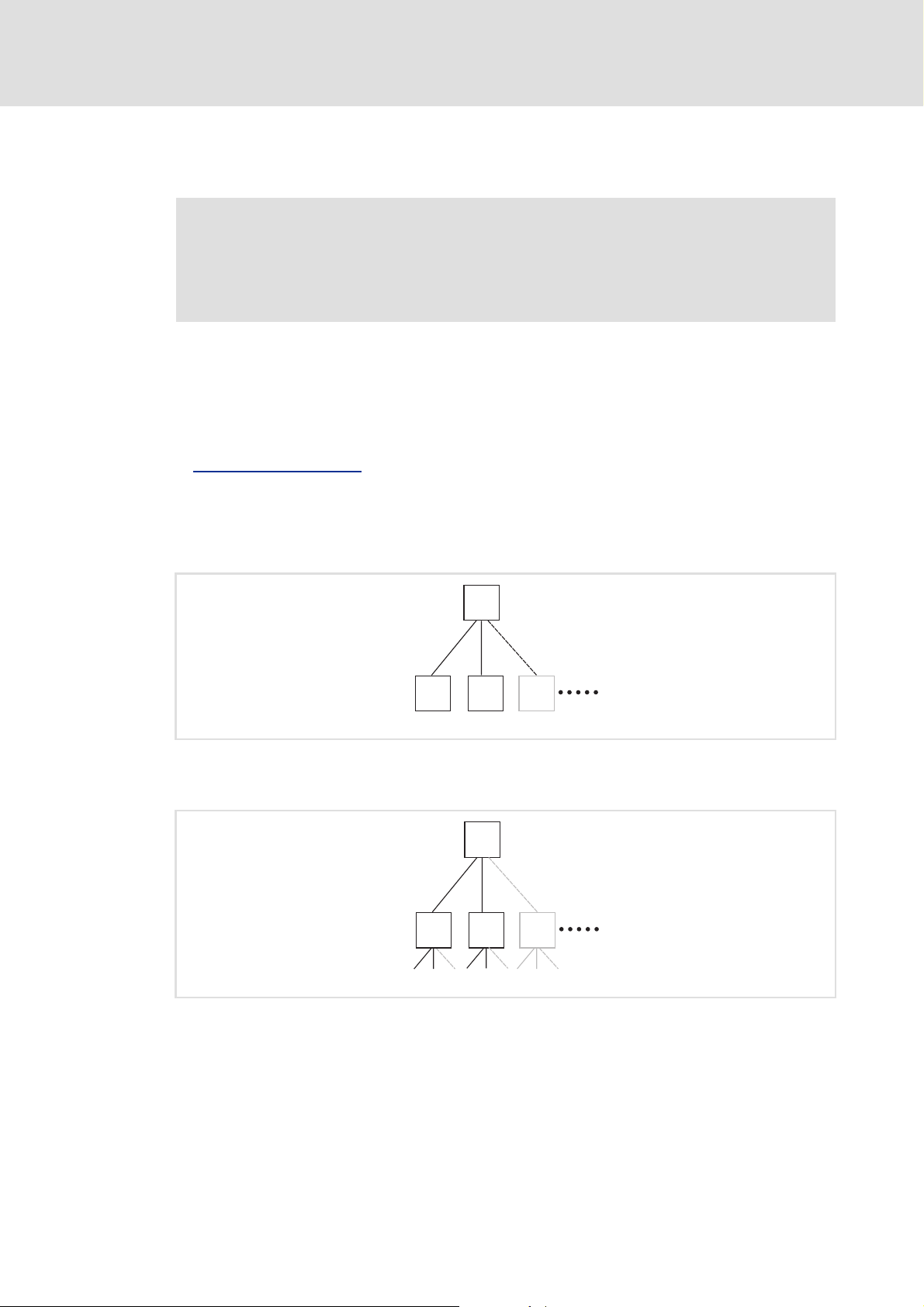
PROFINET supports the following topologies:
Switch / star
( 15)
S
DD
[4-1] Switch / star topology (S = switch, D = IO device)
Tree via switches
C
D
E94YCER005
SS
[4-2] Tree topology (C =IO controller, S = switch)
16 L EDS84DPNET EN 4.0 - 11/2010
S
E94YCER006
Page 17
Communication manual 8400 protec PROFINET
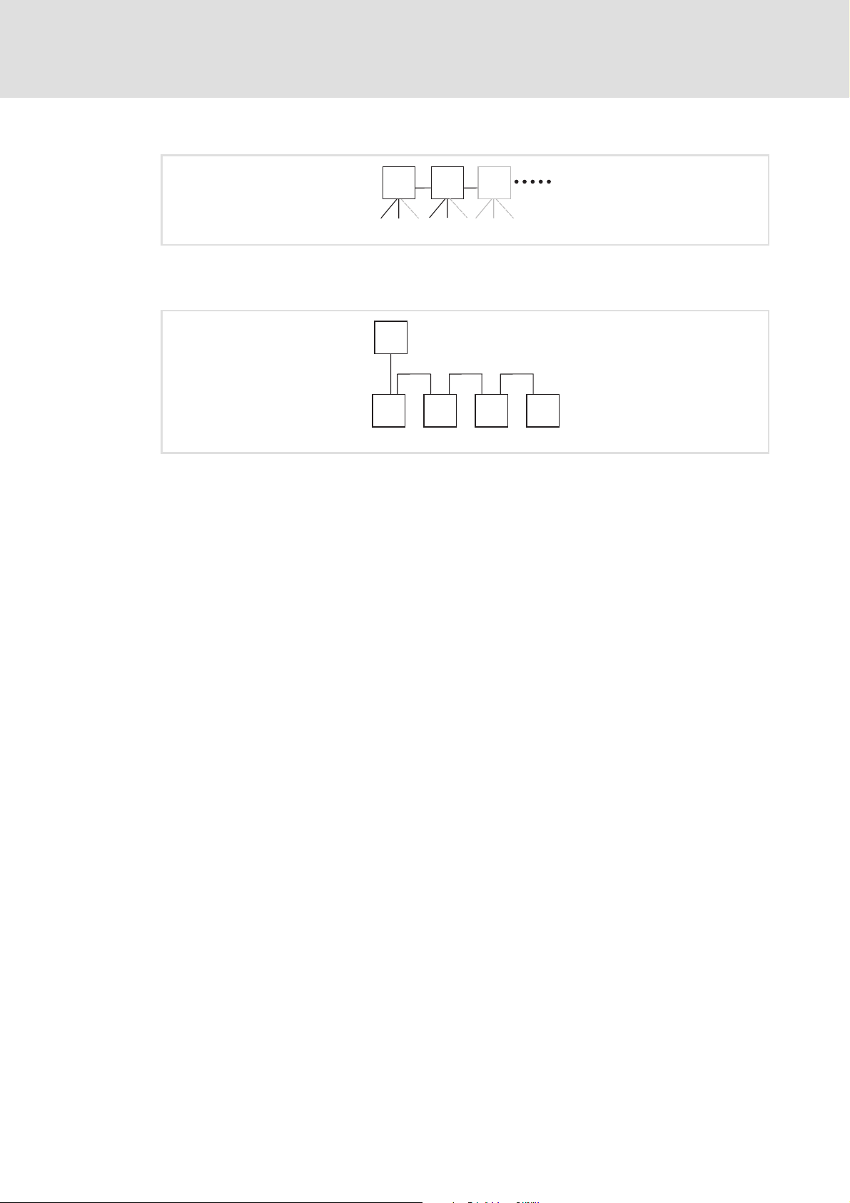
Switch / switch
[4-3] Switch/switch topology (S = switch)
IO controller / IO device
[4-4] Line topology (C = IO controller, D = IO device)
Installation
Network topology
SSS
E94YCER007
C
D D D D
E94YCER008
EDS84DPNET EN 4.0 - 11/2010 L 17
Page 18
Communication manual 8400 protec PROFINET
Installation
PROFINET connection
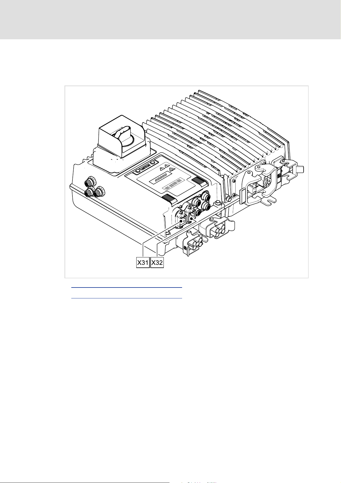
4.2 PROFINET connection
The connection to the PROFINET network is made via the terminals X31 (input) and X32
(output) – depending on the version via an RJ45 socket or an M12 socket.
PROFINET connection via the RJ45 socket
PROFINET connection via the M12 socket
E84DWGA010_Kom
( 19)
( 22)
18 L EDS84DPNET EN 4.0 - 11/2010
Page 19
Communication manual 8400 protec PROFINET
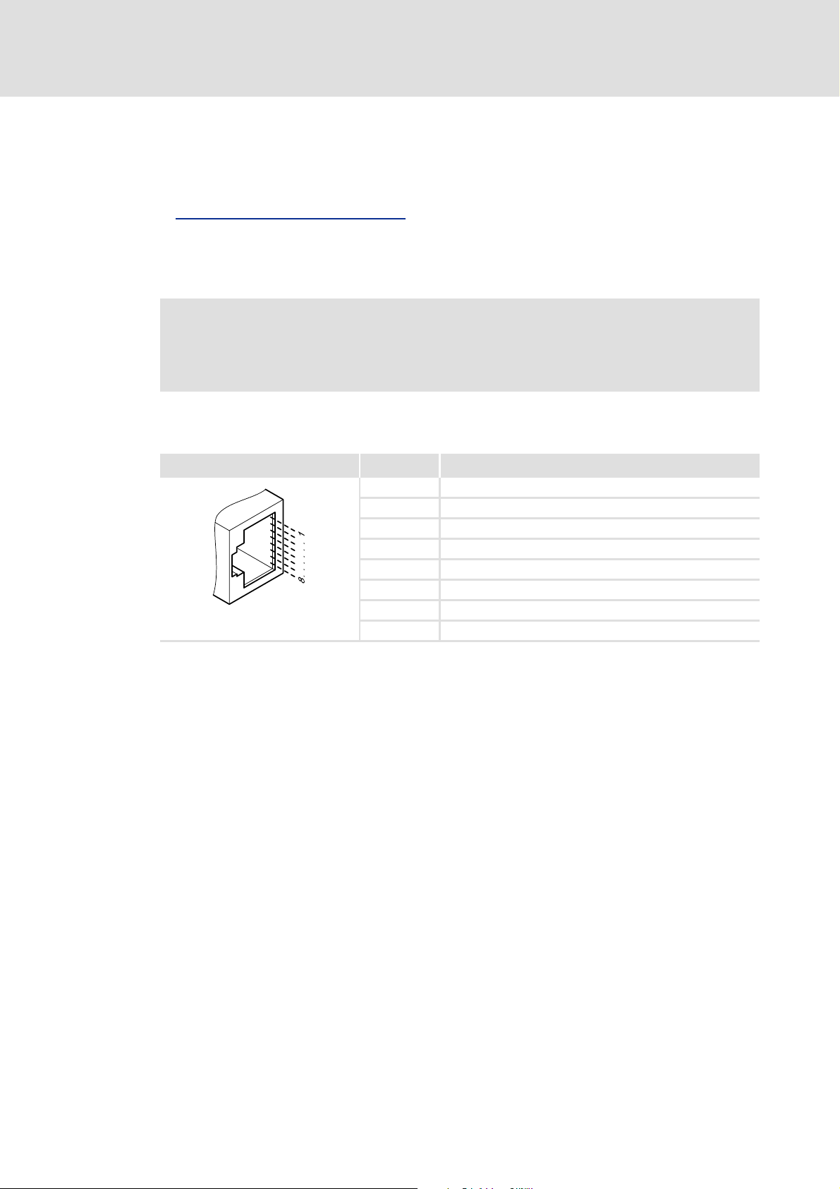
4.2.1 PROFINET connection via the RJ45 socket
A standard Ethernet patch cable is suitable for connecting the Inverter Drive 8400 protec
to a PROFINET network.
Installation
PROFINET connection
Specification of the Ethernet cable
The installation and removal of the Ethernet cables is optimised for the use of connectors
according to the "Automation Initiative of German Domestic Automobile Manufacturers"
(AIDA).
Note!
To prevent the RJ45 socket from being damaged, hold the Ethernet cable
connector vertically when inserting it into or unplugging it from the socket.
4.2.1.1 Pin assignment
RJ45 socket Pin Signal
E94AYCXX004C
( 20)
1Tx +
2Tx -
3Rx +
4-
5-
6Rx -
7-
8-
Tip!
The PROFINET interfaces feature an auto MDIX function. This function adjusts the
polarity of the RJ45 interfaces so that a connection can be established irrespective
of the polarity of the opposite PROFINET interface and irrespective of the type of
cable used (standard patch cable or crossover cable).
EDS84DPNET EN 4.0 - 11/2010 L 19
Page 20
Communication manual 8400 protec PROFINET
Installation
PROFINET connection
4.2.1.2 Specification of the Ethernet cable
Note!
Only use cables that meet the listed specifications.
Specification of the Ethernet cable
Ethernet standard Standard Ethernet (in accordance with IEEE 802.3), 100Base-TX (Fast
Cable type S/FTP (Screened Foiled Twisted Pair, ISO/IEC 11801 or EN 50173), CAT 5e
Damping 23.2 dB (at 100 MHz and per 100 m)
Crosstalk damping 24 dB (at 100 MHz and per 100 m)
Return loss 10 dB (per 100 m)
Surge impedance 100 Ω
Ethernet)
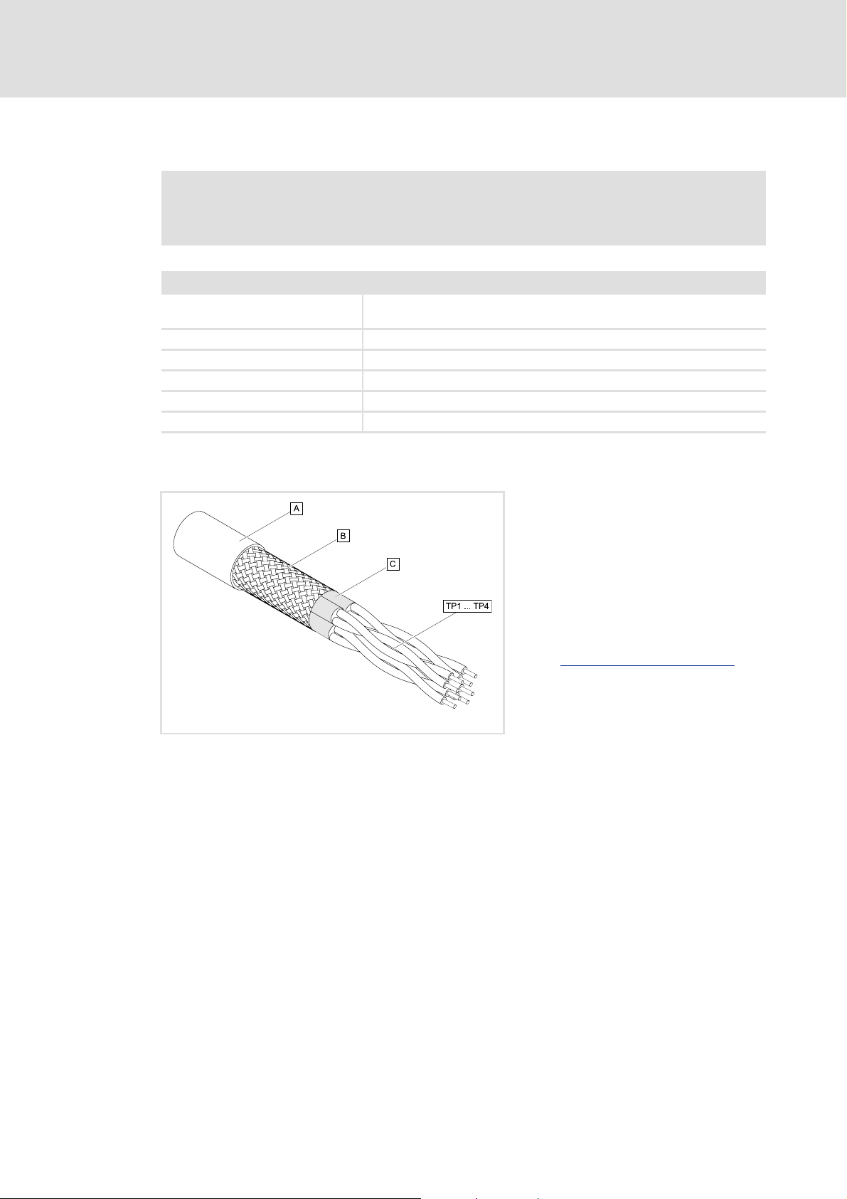
Structure of the Ethernet cable
[4-5] Structure of the Ethernet cable (S/FTP, CAT 5e)
E94YCEP016
A Cable insulation
B Braid
C Foil shield
TP1
Twisted core pairs 1 ... 4
...
Colour code of the Ethernet cable
TP4
( 21)
20 L EDS84DPNET EN 4.0 - 11/2010
Page 21
Communication manual 8400 protec PROFINET
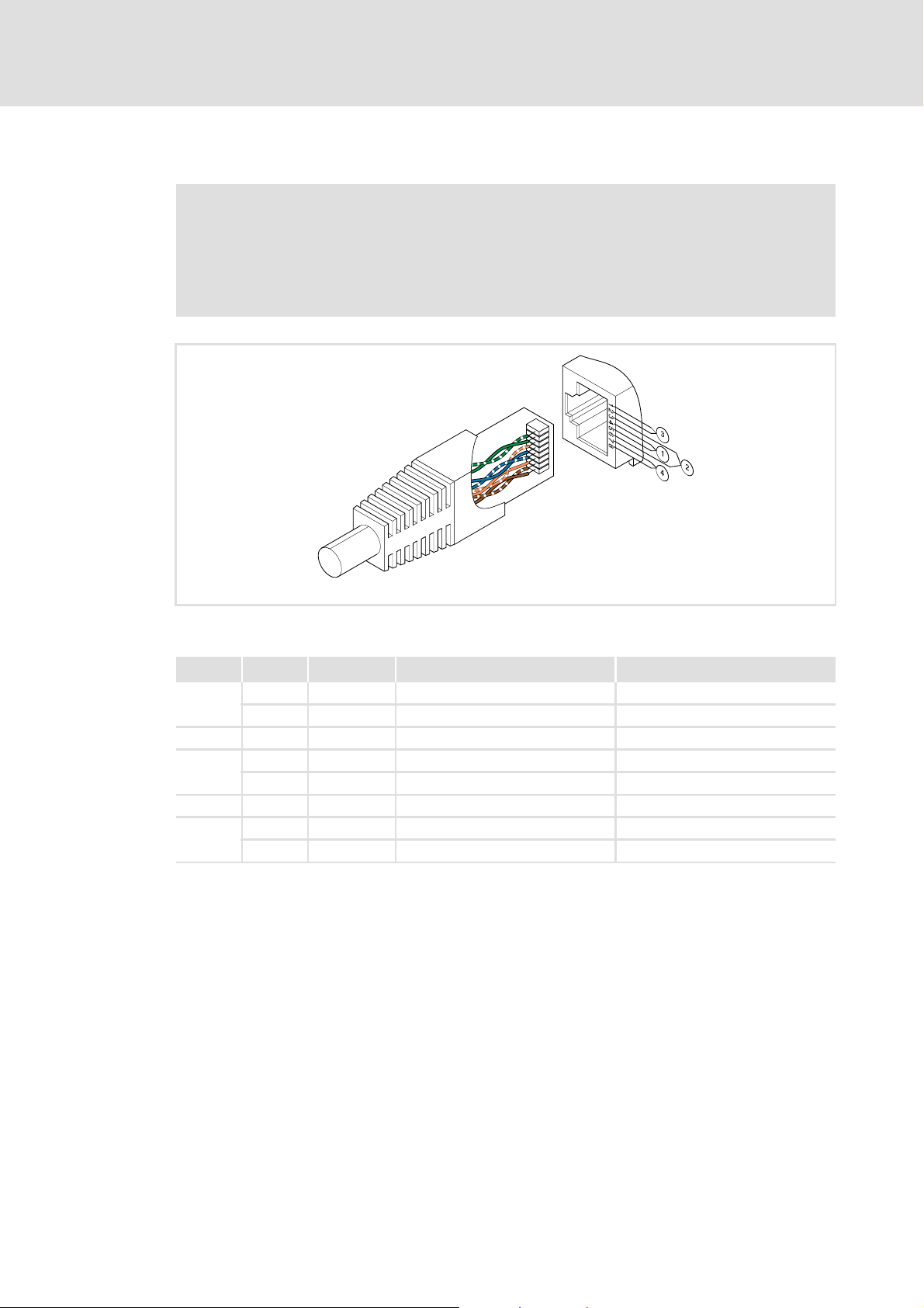
Colour code of the Ethernet cable
Note!
The wiring and colour code are standardised in EIA/TIA 568A/568B.
4-pin Ethernet cables can be used as per the industrial standard. The cable type
only connects the assigned pins 1, 2, 3 and 6 to one another.
Installation
PROFINET connection
[4-6] Ethernet connector in accordance with EIA/TIA 568A/568B
Pair Pin Signal EIA/TIA 568A EIA/TIA 568B
3 1 Tx + White / green White / orange
2 Tx - Green Orange
2 3 Rx + White / orange White / green
1 4 Blue Blue
5 White / blue Blue / white
2 6 Rx - Orange Green
4 7 White / brown White / brown
8Brown Brown
E94YCEI004A
EDS84DPNET EN 4.0 - 11/2010 L 21
Page 22

Communication manual 8400 protec PROFINET
Installation
PROFINET connection
4.2.2 PROFINET connection via the M12 socket
Pin assignment
X31 (input) / X32 (output)
(M12 socket, 4-pin, D-coded)
4
3
1
2
Pin Signal
1Tx +
2Rx +
3Tx -
4Rx -
22 L EDS84DPNET EN 4.0 - 11/2010
Page 23

5 Commissioning
During commissioning system-specific data such as motor paramters, operating
parameters, responses, and parameters for fieldbus communication are specified for the
controller. In the case of Lenze devices this is carried out via the so-called codes.
The controller and communication codes are saved non-volatilely as a data record in the
memory module.
In addition there are diagnostic and monitoring codes for the nodes.
Communication manual 8400 protec PROFINET
Commissioning
Before initial switch-on
Parameter reference
5.1 Before initial switch-on
Stop!
Before you switch on the Inverter Drive 8400 protec for the first time, check the
entire wiring for completeness, short circuit, and earth fault.
( 67)
EDS84DPNET EN 4.0 - 11/2010 L 23
Page 24
Communication manual 8400 protec PROFINET
Commissioning
Configuring the PROFINET IO controller
5.2 Configuring the PROFINET IO controller
First you have to configure the IO controller for communication with the Inverter Drive
8400 protec.
Configuration for the IO controller
For configuring PROFINET, the current PROFINET device description file (XML) of the
Inverter Drive 8400 protec must be imported in the IO controller.
The current device description file GSDML-Vx.z-Lenze-8420-PNabb-yyyymmdd.xml can be
found on the Lenze Internet pages further on in the "Services & Downloads" area at:
www.Lenze.com
Wildcard in the file name "GSDML-Vx.z-Lenze-8420-PNabb-yyyymmdd.xml"
x Main version of the GSDML scheme used
z Subversion of the GSDML scheme used
a Major version of the software version Starting from this 8400 protec PROFINET version, the
bb Minor version of the software version
yyyy Year
mm Month
dd Day
device description file can be used.
Definition of the user data length
The user data length is defined during the initialisation phase of the IO controller.
The Inverter Drives 8400 protec support the configuration of max. 16 process data words
(max. 32 bytes).
Description of the device data base file
Selection text Parameter data
(with consistency)
PCD (nW) AR cons. - n words n words
Safety (4W) AR - 4 words 4 words
n = 1 ... 16 process data words
Process data
(with consistency)
Assigned
I/O memory
Example of device data base file selection
"PCD (8W) AR cons." = process data words (8 words)
"Safety (4W) AR" = safety data words (4 words)
Tip!
A detailed consistency description is provided in the chapter "Consistent
parameter data" ( 53).
24 L EDS84DPNET EN 4.0 - 11/2010
Page 25

5.3 Setting the station name
Note!
• The "Node blinking test" PROFINET function, which serves to identify an
accessible device, is supported. The red LED "BUS-ERR" flickers during
execution (LED status displays
• In the event of impermissible settings, the red LED "BUS-ERR" is blinking. In
this case, the Inverter Drive 8400 protec continues to work internally with the
deleted name. Operation on the PROFINET requires a valid station name.
• If the station name is assigned by the IO controller via PROFINET the change
is activated immediately. The current station name is displayed in code
C13864
The station name ...
.
Communication manual 8400 protec PROFINET
Commissioning
Setting the station name
( 56)).
is required for unambiguous addressing of the Inverter Drive 8400 protec by the IO
controller.
can either be assigned by the IO controller via PROFINET or set manually in the
»Engineer«.
has to be allocated according to the PROFINET specification:
– 1 or several labels separated by ".".
– Max. length per label: 63 characters
– Max. total length: 240 characters
– Permissible characters: [a ... z], [0 ... 9], [.], [-]
– Labels must not begin or end with [-].
Prohibited syntax:
– "n.n.n.n" (n = 0 ... 999)
– "port-xyz" (x,y,z=0...9)
– "port-xyz-abcde" (a,b,c,d,e,x,y,z=0...9)
EDS84DPNET EN 4.0 - 11/2010 L 25
Page 26
Communication manual 8400 protec PROFINET
Commissioning
Setting the station name
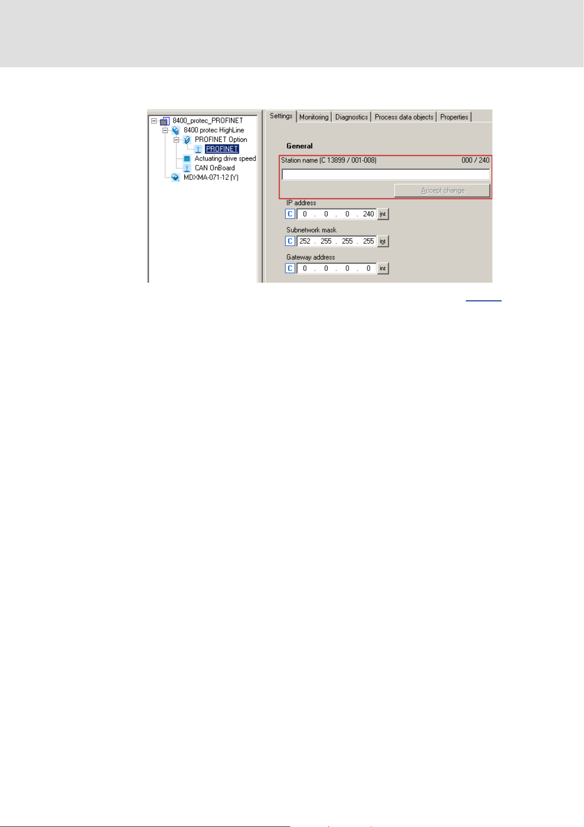
In the »Engineer« the station name is set under the Settings tab.
Then click Accept change. The station name is saved and written to code C13899
In the Lenze setting a deleted name is displayed. The name is also deleted if the "Reset
to factory defaults" command is executed by an IO supervisor or an IO controller.
.
26 L EDS84DPNET EN 4.0 - 11/2010
Page 27

5.4 Setting the IP configuration
If the Inverter Drive 8400 protec is to be made accessible via its IP parameters, the IP
address, subnet mask, and gateway address must either be assigned by the IO controller
via PROFINET, or manually assigned in the »Engineer«.
In the »Engineer« the IP parameters are set under the Settings tab.
Communication manual 8400 protec PROFINET
Commissioning
Setting the IP configuration
Note!
• The IP parameters are written to codes C13000 (IP address), C13001 (subnet
mask), and C13002
Use the [int] buttons to the right of the input fields to change to the decimal
code representation.
• The assignment of invalid combinations of IP address, subnet mask, and
gateway address can have the consequence that no connection to the
PROFINET can be established.
• If settings are impermissible, the red LED "BUS-ERR" blinks (LED status
displays ( 56)).
• If the IP parameters are assigned by the IO controller via PROFINET, the
change is activated immediately. The current parameter values are displayed
in the corresponding codes.
(gateway address) as decimal values.
EDS84DPNET EN 4.0 - 11/2010 L 27
Page 28

Communication manual 8400 protec PROFINET
Commissioning
Setting the IP configuration
IP address (C13000)
Valid IP addresses are defined according to RFC 3330.
C13010
Example: IP address 192.168.0.1
(Sub)code C13010/1
Value 192 168 0 1
Subnetwork mask (C13001
displays the IP address that is currently used.
C13010/2 C13010/3 C13010/4
)
These subnet masks are permissible:
Permissible subnet masks Value in C13001 [dec]
0.0.0.240 ... 128.255.255.255 4026531840 ... 4294967168
192.255.255.255 ... 248.255.255.255 4294967232 ... 4294967288
252.255.255.255 4294967292
C13012
Example: Subnet mask 192.255.255.255
(Sub)code C13011/1
Value 192 255 255 255
Gateway address (C13002
displays the subnet mask that is currently used.
C13011/2 C13011/3 C13011/4
)
The gateway address is valid if the network address of the IP address and the gateway
address are identical.
If the gateway address and the IP address are identical, gateway functionality is not
used.
DHCP is not supported.
C13012
Example: IP address 192.168.0.1
(Sub)code C13012/1
Value 192 168 0 1
displays the gateway address that is currently used.
C13012/2 C13012/3 C13012/4
28 L EDS84DPNET EN 4.0 - 11/2010
Page 29

5.5 Initial switch-on
Mounting instructions "Inverter Drives 8400 protec"
Observe the safety instructions and information on residual hazards.
Note!
Protection against uncontrolled restart
After a fault (e.g. short-term mains failure), it is sometimes undesirable or even
impermissible for the drive to restart.
In the Lenze setting of the Inverter Drives 8400 protec, the restart protection is
activated.
The restart behaviour of the controller can be set via C00142 ("Autostart
option"):
• C00142 = 9 (Lenze setting)
– The controller remains inhibited (even when the fault is no longer active).
– Bit 0 (inhibit at power-on) and bit 3 (inhibit in the case of undervoltage) are
set.
– The drive starts in a controlled mode by an explicit controller enable: LOW-
HIGH edge on a digital input configured correspondingly (terminals X41,
X42, X43).
• C00142 = 8 (enabled)
– In order to enable the device directly when switching it on, set bit 0 to zero.
– An uncontrolled restart of the drive is possible.
Communication manual 8400 protec PROFINET
Commissioning
Initial switch-on
EDS84DPNET EN 4.0 - 11/2010 L 29
Page 30

Communication manual 8400 protec PROFINET
Data transfer
6 Data transfer
PROFINET transmits parameter data, configuration data, diagnostic data, alarm messages,
and process data between the host system (IO controller) and the controllers participating
in the fieldbus (IO devices). Depending on their time-critical behaviour, the data are
transmitted via corresponding communication channels.
Communication channels
The process data channel transmits process data.
– With the process data the controller is actuated.
– The transmission of process data is time-critical.
– Process data are transmitted cyclically between the IO controller and the IO devices
that are part of the fieldbus according to the provider/consumer model (continuous
exchange of current input and output data).
– The IO controller can directly access the process data. In the PLC, for instance, the
data are directly assigned to the IO area.
– In the case of Inverter Drives 8400 protec, maximally 16 process data words (16 bits/
word) can be exchanged for each direction.
– Process data are not stored in the Inverter Drive 8400 protec.
– Process data are e.g. setpoints, actual values, control and status words.
Note!
Please observe the direction of the flow of information!
• Process input data (Rx data):
– Process data from the drive controller (IO device) to the IO controller
• Process output data (Tx data):
– Process data from the IO controller to the drive controller (IO device)
Parameter data are transmitted via the acyclic channel.
– Usually the transmission of parameter data is not time-critical.
– Access to the parameter data depends on the PROFIdrive profile.
– Examples of parameter data are operating parameters, motor data, and diagnostic
information.
– The acyclic channel provides access to all Lenze codes.
– Parameter changes must be saved via code C00002 of the Inverter Drives 8400
protec.
30 L EDS84DPNET EN 4.0 - 11/2010
Page 31

Communication manual 8400 protec PROFINET
/3B0FL,Q
"
/3B0FL2XW
"
7 Process data transfer
7.1 Accessing process data / PDO mapping
The process data (MCI PDOs) are transferred via the MCI interface.
Max. 16 words are exchanged for each direction.
The process data are accessed via the port blocks LP_MciIn and LP_MciOut. The port
blocks are also called process data channels.
The port/function block interconnection of the process data objects (PDO) is made via
the Lenze »Engineer«.
Process data transfer
Accessing process data / PDO mapping
)LHOGEXV
E&WUOB%
E&WUOB%
Z&WUO
E,QB%
E,QB%
Z,Q
Z,Q
GQ,QBS
&RPPXQLFDWLRQRSWLRQ
0&,LQWHUIDFH
$SSOLFDWLRQ
)%LQWHUFRQQHFWLRQ
E6WDWHB%
E6WDWHB%
Z6WDWH
E2XWB%
E2XWB%
Z2XW
Z2XW
GQ2XWBS
[7-1] External and internal data transfer between bus system, controller, and application
Software manual / »Engineer« online help for the Inverter Drive 8400 protec
Here you will find detailed information on the port/function block
interconnection in the »Engineer« and the port blocks.
EDS84DPNET EN 4.0 - 11/2010 L 31
Page 32

Communication manual 8400 protec PROFINET
Process data transfer
Preconfigured port interconnection of the process data objects (PDO)
Note!
The »Engineer« screenshots shown in the following are only examples of the
setting sequence and the resulting displays.
The data in the display fields may differ from the ones of your project.
7.2 Preconfigured port interconnection of the process data objects (PDO)
The preconfigured port interconnection of the process data objects can be activated by
setting standard device code C00007 = "40: MCI".
The function block editor (FB Editor) serves to display the port blocks "LP_MciIn" and
"LP_MciOut" with the preconfigured interconnections:
32 L EDS84DPNET EN 4.0 - 11/2010
Page 33
Communication manual 8400 protec PROFINET
Process data transfer
Freely configuring the port interconnection of the process data objects (PDO)
7.3 Freely configuring the port interconnection of the process data objects (PDO)
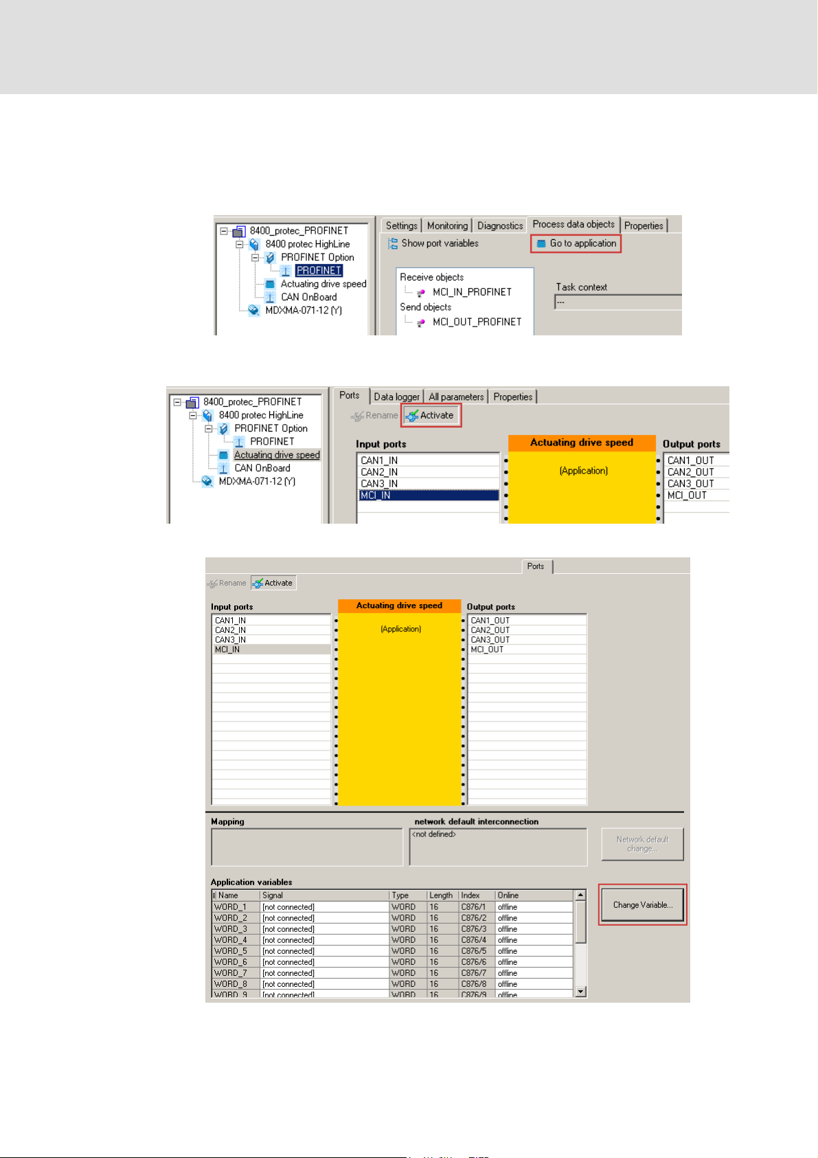
How to freely configure the port interconnection in the »Engineer«:
1. Go to the Process data objects tab and click Go to application.
2. Go to the Ports ta b, selec t the port blocks "MCI _IN" or "MCI_ OUT" and cl ick Activate
to activate them.
3. Click the Change variable ... button.
EDS84DPNET EN 4.0 - 11/2010 L 33
Page 34

Communication manual 8400 protec PROFINET
Process data transfer
Freely configuring the port interconnection of the process data objects (PDO)
4. The button serves to assign signals to the process data words in the Assignment
signal --> function block dialog box.
Select signals and then click the OK button.
34 L EDS84DPNET EN 4.0 - 11/2010
Page 35

Communication manual 8400 protec PROFINET
Process data transfer
Freely configuring the port interconnection of the process data objects (PDO)
Moreover you can assign signals to the individual control and status bits at the
WORD_1 and WORD_2 process data words via the and buttons.
Select the signals and then click OK.
EDS84DPNET EN 4.0 - 11/2010 L 35
Page 36

Communication manual 8400 protec PROFINET
Process data transfer
Freely configuring the port interconnection of the process data objects (PDO)
Tip!
When the port blocks "LP_MciIn" and "LP_MciOut" are activated (see 1.), they will
be visible in the FB Editor. Here you can also assign signals to the process data
words.
36 L EDS84DPNET EN 4.0 - 11/2010
Page 37

Communication manual 8400 protec PROFINET
P
l
8 Parameter data transfer
8.1 The acyclic channel (PROFIdrive profile)
An optional service extension is the acyclic parameter data transfer.
Cyclic and acyclic PROFINET services can be operated simultaneously in the network.
Properties
Only one parameter request is processed at a time (no pipelining).
Spontaneous messages are not transmitted.
There are only acyclic parameter requests.
Profile-specific parameters can be read independently of the IO device state.
Parameter data transfer
The acyclic channel (PROFIdrive profile)
8.1.1 Connection establishment of an IO controller to an IO device
An IO controller can always be used to request parameters from an IO device if the IO
device is in the "DATA_EXCHANGE" state.
arameterdata channe
Read
IO device
Write
[8-1] Data communication via the acyclic channel
IO
controller
E94YCER010
EDS84DPNET EN 4.0 - 11/2010 L 37
Page 38

Communication manual 8400 protec PROFINET
Parameter data transfer
The acyclic channel (PROFIdrive profile)
8.1.2 Acyclic data transmission process
IO controller
Parameter request
[8-2] Data communication via the acyclic channel
A "Write.req" is used to transmit the data set (DB47) in the form of a parameter request
to the IO device.
"Write.res" confirms the receipt of the message by the IO controller.
The IO controller requests the response of the IO device with "Read.req".
Write.req (DB47)
with data (parameter request)
Write.res
without data
Read.req
without data
Read.res (-)
without data
Read.req
without data
Read.res (+)Parameter response
with data (parameter response)
IO device
Parameter request
Parameter response
Parameter
processing
E94YCER011
The IO device responds with a "Read.res (-)" if processing is not yet completed.
After parameter processing, the parameter request is completed by transmitting the
parameter response in the form of a "Read.res (+)" to the IO controller.
38 L EDS84DPNET EN 4.0 - 11/2010
Page 39

Communication manual 8400 protec PROFINET
8.1.3 Structure of the PROFINET data telegram
Parameter data transfer
The acyclic channel (PROFIdrive profile)
Dest
Addr
6 bytes 6 bytes 4 bytes 4 bytes 80 bytes 64 bytes 64 bytes 0 ... 240 bytes 4 bytes
[8-3] PROFINET data telegram
Scr
Addr
VLAN
Day
Type
0800H
RPC NDR Read/Write
Block
Data FSC
In the "Read/Write Block", the initiator specifies the access to data set "DB47". The data
which are written to this index or read by it contain a header and the parameter request,
or the parameter response. The data read or the data to be written are contained in the
"Data" field.
The following subchapters describe the parameter request and the parameter response in
detail.
PROFINET specification
Here you will find detailed information on the PROFINET data telegram.
Assignment of the user data in dependence on the data type
Depending on the data type, the user data are assigned as follows:
Data type Length User data assignment
Byte 1 Byte 2 Byte 3 Byte 4 Byte ...
String x bytes
U8 1 byte 00
U16 2 bytes
U32 4 bytes
High byte Low byte
High word Low word
High byte Low byte High byte Low byte
EDS84DPNET EN 4.0 - 11/2010 L 39
Page 40

Communication manual 8400 protec PROFINET
Parameter data transfer
Reading parameters from the controller
8.2 Reading parameters from the controller
Note!
• When a read request is processed, no parameter value is written to the IO
device.
• In the case of a multi-parameter read request, the parameter attribute, index,
and subindex are repeated "n" times, "n" being the number of parameters
requested.
Request header
Byte 1 Byte 2 Byte 3 Byte 4
Request reference Job identification Axis Number of indices
Field Data type Values
Request reference U8 This value is specified by the IO controller.
Job identification U8 0x01: Request parameter for reading
Axis U8 0x00 or 0x01
Number of indices U8 0x"n" (n = number of parameters requested)
Parameter attribute
Byte 5 Byte 6
Attribute Number of subindices
Field Data type Values
Attribute U8 0x10: Value
Number of subindices U8 0x00 or 0x01
Index and subindex
Byte 7 Byte 8 Byte 9 Byte 10
Index Subindex
High byte Low byte High byte Low byte
Field Data type Values
Index U16 0x0001 ... 0xFFFF (1 ... 65535)
Subindex U16 0x0001 ... 0xFFFF (1 ... 65535)
40 L EDS84DPNET EN 4.0 - 11/2010
Page 41

Communication manual 8400 protec PROFINET
8.2.1 Response after a correct read request
Note!
• Responses to read requests do not contain parameter attributes and indexes/
subindexes.
• When a multi-parameter read request is transmitted, the parameter format
and the parameter value are repeated "n" times, "n" being the number of
parameters requested.
Response header
Byte 1 Byte 2 Byte 3 Byte 4
Request reference
(mirrored)
Response identifier Axis
Parameter data transfer
Reading parameters from the controller
Number of indices
(mirrored)
Field Data type Values
Request reference U8 Mirrored value of parameter request
Response identifier U8 0x01: Parameter read
Axis U8 0x00 or 0x01
Number of indices U8 0x"n" (n = number of parameters requested)
Parameter format
Byte 5 Byte 6
Format Number of values
Field Data type Values
Format U8 0x02: Integer8
0x03: Integer16
0x04: Integer32
0x05: Unsigned8
0x06: Unsigned16
0x07: Unsigned32
0x09: Visible string
0x0A: Octet string
0x40: Zero
0x41: Byte
0x42: Word
0x43: Double word
Number of values U8 • 0x01
• Number of requested subindices. (If there is more
than one subindex, only the parameter value is
repeated.)
• In the case of string codes, the number of characters
is entered here.
EDS84DPNET EN 4.0 - 11/2010 L 41
Page 42

Communication manual 8400 protec PROFINET
Parameter data transfer
Reading parameters from the controller
Parameter value
Byte 7 Byte 8 Byte 9 Byte 10
Value
Field Data type Values
Value String Any
U8 0x00 .... 0xFF
U16 0x0000 .... 0xFFFF
U32 0x0000 0000 .... 0xFFFF FFFF
8.2.2 Response after a read error
Response header
Byte 1 Byte 2 Byte 3 Byte 4
Request reference
(mirrored)
Field Data type Values
Request reference U8 Mirrored value of parameter request
Response identifier U8 0x81: Parameter not read
Axis U8 0x00 or 0x01
Number of indices U8 0x"n" (n = number of parameters requested)
Response identifier Axis
(mirrored)
• The data in bytes 7 + 8 are to be interpreted as error
Number of indices
code.
Parameter format
Byte 5 Byte 6
Format Number of values
Field Data type Values
Format U8 0x44: Error
Number of values U8 0x01: Error code without additional information
0x02: Error code with additional information
42 L EDS84DPNET EN 4.0 - 11/2010
Page 43

Communication manual 8400 protec PROFINET
Error code
Byte 7 Byte 8 Byte 9 Byte 10
Error code Additional information (if available)
High byte Low byte High byte Low byte
Field Data type Values
Error code U16 0x0000 .... 0xFFFF
Additional information
(if available)
8.2.3 Telegram example: Read request
The heatsink temperature of the controller is to be read.
Code to be read: C00061
U16
Parameter data transfer
Reading parameters from the controller
Error information (error)
( 51)
Heatsink temperature: 43 °C
Parameter request
Byte 1 Byte 2 Byte 3 Byte 4
Request reference Job identification Axis Number of indices
0xXX 0x01 0x00 0x01
Request parameter for reading
Byte 5 Byte 6
Attribute Number of subindices
0x10 0x00
Value No subindex
Byte 7 Byte 8 Byte 9 Byte 10
Index Subindex
High byte Low byte High byte Low byte
0x5F 0xC2 0x00 0x00
Index = 24575 - code no. = 24575 - 61 = 24514 = 0x5F C2 No subindex
EDS84DPNET EN 4.0 - 11/2010 L 43
Page 44

Communication manual 8400 protec PROFINET
Parameter data transfer
Reading parameters from the controller
Parameter response after a correct read request
Byte 1 Byte 2 Byte 3 Byte 4
Request reference Response identifier Axis Number of indices
0xXX 0x01 0x00 0x01
(mirrored) Parameter read (mirrored)
Byte 5 Byte 6
Format Number of values
0x43 0x01
Double word 1 value
Byte 7 Byte 8 Byte 9 Byte 10
Value
High word: high byte High word: low byte Low word: high byte Low word: low byte
0x00 0x00 0x00 0x2B
Read value = 0x00 00 00 2B = 43 x 1 (internal factor) = 43 [°C]
Parameter response to a read error
Byte 1 Byte 2 Byte 3 Byte 4
Request reference Response identifier Axis Number of indices
0xXX 0x81 0x00 0x01
(mirrored) Parameter not read (mirrored)
Byte 5 Byte 6
Format Number of values
0x44 0x01
Error Error code without additional
Byte 7 Byte 8
Error code
High byte Low byte
For the meaning, see the chapter "Error information
(error)" ( 51)
information
44 L EDS84DPNET EN 4.0 - 11/2010
Page 45
Communication manual 8400 protec PROFINET
8.3 Writing parameters to the controller
Note!
• When a multi-parameter write request is processed, the parameter attribute,
index, subindex, and then the parameter format and parameter value are
repeated "n" times, "n" being the number of parameters requested.
• A parameter request must not exceed the max. data length of 240 bytes.
Request header
Byte 1 Byte 2 Byte 3 Byte 4
Request reference Job identification Axis Number of indices
Field Data type Values
Request reference U8 This value is specified by the IO controller.
Job identification U8 0x02: Write parameter
Axis U8 0x00 or 0x01
Number of indices U8 0x"n" (n = number of parameters requested)
Parameter data transfer
Writing parameters to the controller
Parameter attribute
Byte 5 Byte 6
Attribute Number of subindices
Field Data type Values
Attribute U8 0x10: Value
Number of subindices U8 0x00 or 0x01
Index and subindex
Byte 7 Byte 8 Byte 9 Byte 10
Index Subindex
High byte Low byte High byte Low byte
Field Data type Values
Index U16 0x0001 ... 0xFFFF (1 ... 65535)
Subindex U16 0x0001 ... 0xFFFF (1 ... 65535)
EDS84DPNET EN 4.0 - 11/2010 L 45
Page 46

Communication manual 8400 protec PROFINET
Parameter data transfer
Writing parameters to the controller
Parameter format
Byte 11 Byte 12
Format Number of values
Field Data type Values
Format U8 0x02: Integer8
0x03: Integer16
0x04: Integer32
0x05: Unsigned8
0x06: Unsigned16
0x07: Unsigned32
0x09: Visible string
0x0A: Octet string
0x40: Zero
0x41: Byte
0x42: Word
0x43: Double word
Number of values U8 • 0x01
• Number of requested subindices. (If there is more
• In the case of string codes, the number of characters
than one subindex, only the parameter value is
repeated.)
is entered here.
Parameter value
Byte 13 Byte 14 Byte 15 Byte 16
Value
Field Data type Values
Value String Any
U8 0x00 .... 0xFF
U16 0x0000 .... 0xFFFF
U32 0x0000 0000 .... 0xFFFF FFFF
46 L EDS84DPNET EN 4.0 - 11/2010
Page 47

Communication manual 8400 protec PROFINET
8.3.1 Response after a correct write request
Response header
Byte 1 Byte 2 Byte 3 Byte 4
Request reference
(mirrored)
Field Data type Values
Request reference U8 Mirrored value of parameter request
Response identifier U8 0x01: Parameter written
Axis U8 0x00 or 0x01
Number of indices U8 0x"n" (n = number of parameters requested)
8.3.2 Response after a write error
Response identifier Axis
Parameter data transfer
Writing parameters to the controller
Number of indices
(mirrored)
Note!
For a multi-parameter request, correct and faulty messages, if any, are combined
in one telegram. The individual messages have the following data contents:
• Correct message
– Format: 0x40
– Number of values: 0x00
• Faulty message
– Format: 0x44
– Number of values: 0x01 or 0x02
– Error code without additional information (number of values = 0x01) or
– Error code with additional information (number of values = 0x02)
Faulty access to a parameter "n" will be reported in the response message of a
multi-parameter request at position n.
EDS84DPNET EN 4.0 - 11/2010 L 47
Page 48

Communication manual 8400 protec PROFINET
Parameter data transfer
Writing parameters to the controller
Response header
Byte 1 Byte 2 Byte 3 Byte 4
Request reference
(mirrored)
Field Data type Values
Request reference U8 Mirrored value of parameter request
Response identifier U8 0x82: Parameter not written
Axis U8 0x00 or 0x01
Number of indices U8 0x"n" (n = number of parameters requested)
Parameter format
Response identifier Axis
(mirrored)
• The data in bytes 7 + 8 are to be interpreted as error
Number of indices
code.
Byte 5 Byte 6
Format Number of values
Field Data type Values
Format U8 0x44: Error
Number of values U8 0x01: Error code without additional information
0x02: Error code with additional information
Error code
Byte 7 Byte 8 Byte 9 Byte 10
Error code Additional information (if available)
High byte Low byte High byte Low byte
Field Data type Values
Error code U16 0x0000 .... 0xFFFF
Additional information
(if available)
Error information (error)
U16
( 51)
48 L EDS84DPNET EN 4.0 - 11/2010
Page 49

Communication manual 8400 protec PROFINET
8.3.3 Telegram example: Write request
In the controller, the ramp time for quick stop is to be set to 50 ms.
Code to be written to: C00105
Parameter request
Byte 1 Byte 2 Byte 3 Byte 4
Request reference Job identification Axis Number of indices
0xXX 0x02 0x00 0x01
Write parameter Axis 0 1 index
Byte 5 Byte 6
Attribute Number of subindices
0x10 0x00
Value No subindex
Parameter data transfer
Writing parameters to the controller
Byte 7 Byte 8 Byte 9 Byte 10
Index Subindex
High byte Low byte High byte Low byte
0x5F 0x96 0x00 0x00
Index = 24575 - code no. = 24575 - 105 = 24470 = 0x5F 96 No subindex
Byte 11 Byte 12
Format Number of values
0x43 0x01
Double word 1 value
Byte 13 Byte 14 Byte 15 Byte 16
Value
High word: high byte High word: low byte Low word: high byte Low word: low byte
0x00 0x00 0x00 0x32
Value to be written = 0.05 [s] x 1000 (internal factor) = 50 = 0x00 00 00 32
EDS84DPNET EN 4.0 - 11/2010 L 49
Page 50

Communication manual 8400 protec PROFINET
Parameter data transfer
Writing parameters to the controller
Parameter response after a correct write request
Byte 1 Byte 2 Byte 3 Byte 4
Request reference Response identifier Axis Number of indices
0xXX 0x02 0x00 0x01
(mirrored) Parameter written (mirrored) 1 index
Parameter response after write error
Byte 1 Byte 2 Byte 3 Byte 4
Request reference Response identifier Axis Number of indices
0xXX 0x82 0x00 0x01
(mirrored) Parameter not written (mirrored) 1 index
Byte 5 Byte 6
Format Number of values
0x44 0x01
Fault Error code without additional
information
Byte 7 Byte 8
Error code
High byte Low byte
For the meaning, see the chapter "Error information
(error)" ( 51)
50 L EDS84DPNET EN 4.0 - 11/2010
Page 51

8.4 Error information (error)
Communication manual 8400 protec PROFINET
Parameter data transfer
Error information (error)
Error code Meaning Description Additional
0x0000 Impermissible parameter
number
0x0001 Parameter value cannot be
changed
0x0002 Lower or upper value limit
exceeded
0x0003 Faulty subindex Access to unavailable subindex Subindex
0x0004 No array Access with subindex to non-indexed parameter -
0x0005 Incorrect data type Change access with value that does not match the
0x0006 Setting not permitted (can
only be reset)
0x0007 Description element cannot
be changed
0x0008 Reserved (PROFIdrive Profile V2: PPO-Write requested in IR is
0x0009 No description data available Access to unavailable description (parameter value is
0x000A Reserved (PROFIdrive Profile V2: Wrong access group) -
0x000B No parameter change rights Change access without parameter change rights -
0x000C Reserved (PROFIdrive Profile V2: Wrong password) -
0x000D Reserved (PROFIdrive Profile V2: Text cannot be read in cyclic
0x000E Reserved (PROFIdrive Profile V2: Name cannot be read in cyclic
0x000F No text array available Access to unavailable text array (parameter value is
0x0010 Reserved (PROFIdrive Profile V2: No PPO-Write) -
0x0011 Request cannot be executed
because of operating state
0x0012 Reserved (PROFIdrive Profile V2: Other error) -
0x0013 Reserved (PROFIdrive Profile V2: Date cannot be read in cyclic
0x0014 Impermissible value Change access with a value that is within the value
0x0015 Response too long The length of the current response exceeds the
0x0016 Impermissible parameter
address
0x0017 Impermissible format Write req uest: Impermissible parameter data format
0x0018 Number of values not
consistent
0x0019 Reserved - -
...
0x0064
Access to unavailable parameter -
Change access to a parameter value that cannot be
changed
Change access with value outside the value limits Subindex
data type of the parameter
Change access with non-zero value where this is not
permitted
Change access to a description element that cannot
be changed
not available)
available)
data transfer)
data transfer)
available)
Access is not possible for temporary reasons that are
not specified in detail
data transfer)
limits but is not permissible for other permanent
reasons (parameter with defined single values)
maximum transmittable length
Impermissible value or value which is not supported
for the attribute, number of subindexes, parameter
number, or subindex, or a combination
or parameter data format which is not supported
Write request: Number of parameter data values
does not match the number of subindexes in the
parameter address
information
Subindex
-
Subindex
Subindex
-
-
-
-
-
-
-
Subindex
-
-
-
-
EDS84DPNET EN 4.0 - 11/2010 L 51
Page 52

Communication manual 8400 protec PROFINET
Parameter data transfer
Error information (error)
Error code Meaning Description Additional
0x0065 Manufacturer-specific - -
...
0x00FF
information
52 L EDS84DPNET EN 4.0 - 11/2010
Page 53

8.5 Consistent parameter data
In the PROFINET communication system, data are permanently exchanged between the
host (CPU + IO controller) and the Inverter Drive 8400 protec. The IO controller as well as
the CPU (central processing unit) of the host access a joint memory: the dual port
memory (DPM).
The DPM allows data exchange in both directions (write/read):
Communication manual 8400 protec PROFINET
Parameter data transfer
Consistent parameter data
Central processing unit
(CPU)
Dual port memory
(DPM)
IO controller
It could happen that a slower IO controller writing would be overtaken by a faster CPU
reading within a cycle time without any further data organisation.
To avoid such an impermissible state, the parameter data to be transmitted must be
marked as "consistent".
Data communication with consistency
With consistency, either "reading" or "writing" is possible when the IO controller and the
CPU simultaneously access the memory:
The IO controller transfers data only as a complete data set.
The CPU can only access completely updated data sets.
The IO controller cannot read or write data as long as the CPU accesses consistent data.
The result becomes clear from the example below:
Central processing unit
(CPU)
CPU wants to read. IO controller wants to write at the same
Dual port memory
(DPM)
time.
IO controller
1. As the IO controller can only write when the CPU does not read, the IO controller has to
wait until the data are completely read by the CPU.
2. The IO controller only writes a complete data set into the DPM.
Configuring consistent data
Note!
Consistency is achieved by an appropriate IO controller configuration.
Please refer to the corresponding documentation of your configuration
software.
EDS84DPNET EN 4.0 - 11/2010 L 53
Page 54

Communication manual 8400 protec PROFINET
PROFIsafe
9PROFIsafe
PROFINET enables the transmission of safe information via the PROFIsafe protocol
according to the "PROFIsafe - Profile for Safety Technology" specification, version 2.0.
Note!
Safe information can only be transmitted via the PROFIsafe protocol when using
a version with integrated safety system.
The PROFIsafe messages are sent in the second slot of a PROFINET telegram.
In the PROFIsafe messages, every bit serves to control a specific safety function.
The structure of the PROFIsafe messages is described in the PROFIsafe profile.
The length of the PROFIsafe messages is always 8 bytes.
Safety engineering manual "Inverter Drives 8400 protec"
Here you can find detailed information on devices with an integrated safety
system.
Software manual/»Engineer« online help for the Inverter Drive 8400 protec
Here you can find detailed information about the PROFIsafe connection.
54 L EDS84DPNET EN 4.0 - 11/2010
Page 55

10 Monitoring
Interruption of PROFINET communication
An interruption of PROFINET communication in the DATA_EXCHANGE state, e.g. by cable
break or failure of the IO controller is recognised by the IO device.
The response to the interruption of communication is controlled via the following
settings:
1. During the initialisation of PROFINET communication the watchdog monitoring
time specified in the IO controller is transferred to the IO device.
If the IO device does not receive any valid process data in the DATA_EXCHANGE
state, the process data are treated according to the setting in C13885
the data that were sent last by the IO controller can be used or set to zero.)
After the watchdog monitoring time has elapsed, the IO device changes to the
NO_DATA_EXCHANGE state (see C13861
(LED status displays
Communication manual 8400 protec PROFINET
Monitoring
. (Like this
), and the red LED "BUS-ERR" is activated
( 56)).
There is no reponse in the IO device
2. To trigger a response in the IO device, you additionally have to set a Response of
the Inverter Drive 8400 protec (C13880
By setting a Response delay (C13881
The response delay elapses when the DATA_EXCHANGE status is exited.
After this response delay has elapsed, the response set is executed with the error
message "PROFINET: Data_Exchange status quit [0x01bc6531]
.
) under the Monitoring tab.
) you can decelerate this response.
" ( 64).
EDS84DPNET EN 4.0 - 11/2010 L 55
Page 56

Communication manual 8400 protec PROFINET
Diagnostics
LED status displays
11 Diagnostics
For purposes of fault diagnostics of the PROFINET module, the Inverter Drive 8400 protec
is provided with the LEDs on the front. Furthermore you can carry out the Diagnostics with
the »Engineer« ( 58).
Safety engineering manual "Inverter Drives 8400 protec"
Here you can find detailed information on the LED status displays for devices
with an integrated safety system.
11.1 LED status displays
[11-1] LED display on the front of the Inverter Drive 8400 protec
56 L EDS84DPNET EN 4.0 - 11/2010
Page 57
Communication manual 8400 protec PROFINET
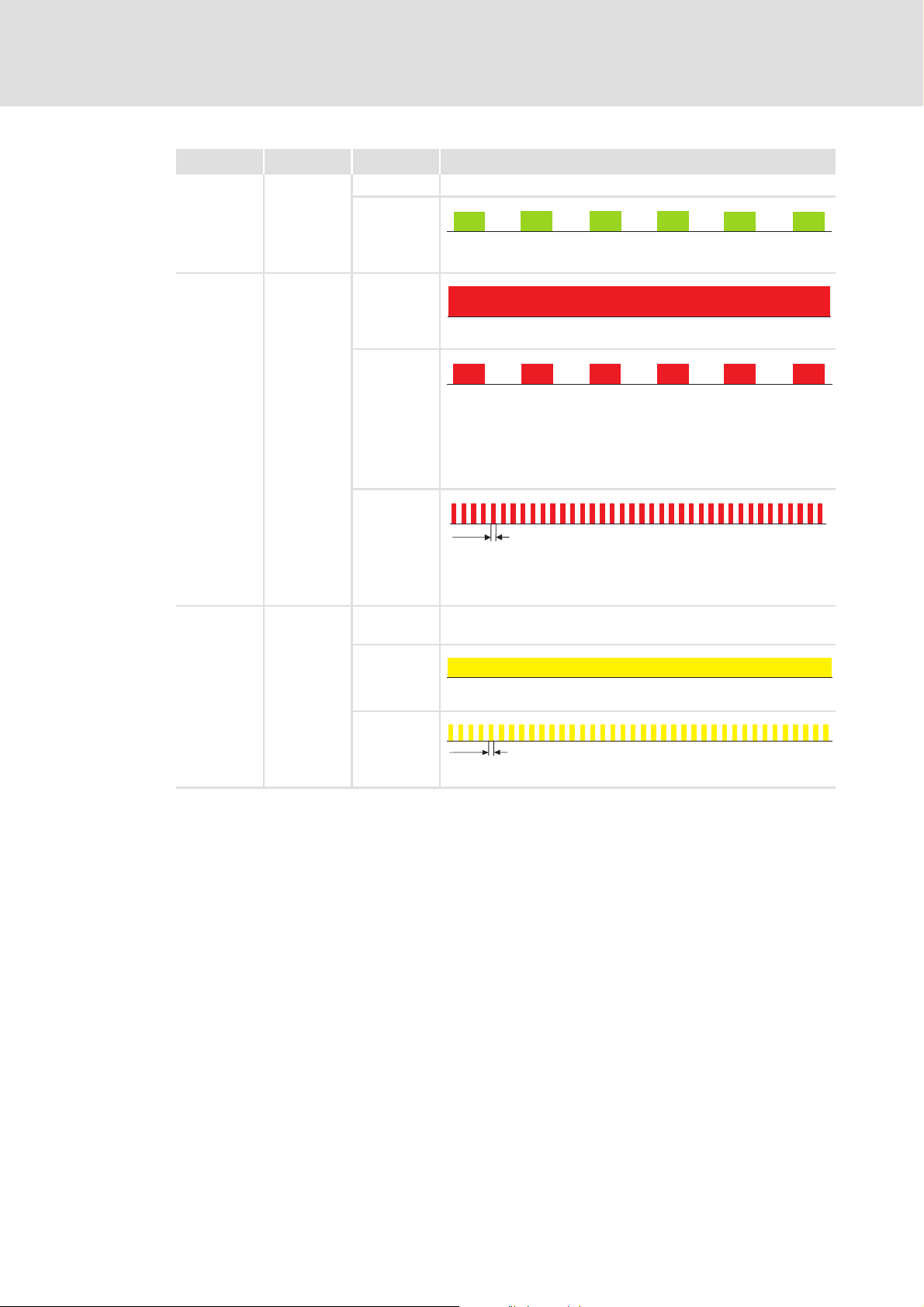
Pos. Colour Status Description
BUS-RDY Green Off No communication
Blinking
200 ms
200 ms
Communication active
BUS-ERR Red On
Communication error (e.g. Ethernet cable has been unplugged)
Diagnostics
LED status displays
Link1
Link2
Blinking
200 ms
200 ms
Impermissible settings:
• Invalid station name
• Invalid IP parameters
The Inverter Drive 8400 has been initialised and continues to work
internally with the respective standard values.
Jittering
50 ms
The "Node blinking test" PROFINET function is activated by the IO
controller.
The jittering LED serves to identify/localise accessible IO devices.
Yellow Off • No cable connected
• No communication
On
Cable connected
Jittering
50 ms
Communication active
EDS84DPNET EN 4.0 - 11/2010 L 57
Page 58

Communication manual 8400 protec PROFINET
Diagnostics
Diagnostics with the »Engineer«
11.2 Diagnostics with the »Engineer«
In the »Engineer« under the Diagnostics tab, various pieces of PROFINET diagnostic
information can be displayed.
58 L EDS84DPNET EN 4.0 - 11/2010
Page 59

11.3 Diagnostic data
The IO device sends an alarm message to the IO controller to signalise the diagnostic
data below.
Communication manual 8400 protec PROFINET
Diagnostics
Diagnostic data
Code C13887
serves to inhibit the transmission of alarm messages to the IO controller.
By this, errors of a specific type can be suppressed systematically.
Errors and warnings in the Inverter Drive 8400 protec are sent to the IO controller as
extended diagnostic messages.
The diagnostic data can be displayed using the hexadecimal representation of the
Siemens S7 engineering tool.
Bytes Meaning Value [hex]
1 ... 6 Diagnostic block header 0x0010 001C 0100
7 ... 8 Alarm type 0x0001 (Diagnosis)
9 ... 12 API (Application Programming Interface) 0x0000 0000
13, 14 Slot number 0x0001 / 0x0002
15, 16 Subslot number 0x0001
17 ... 20 Module ID ID according to module
21 ... 24 Submodule number ID according to module
25, 26 Alarm specification 0xB000
27, 28 User structure ID 0x0001
29 ... 32 Error code of the Inverter Drive 8400 protec
EDS84DPNET EN 4.0 - 11/2010 L 59
Page 60

Communication manual 8400 protec PROFINET
Diagnostics
Diagnostic data
Error code of the Inverter Drive 8400 protec
30
31
Bit
29
Byte 32 Byte 31 Byte 30 Byte 29
[11-2] Error code of the Inverter Drive 8400 protec
Bytes 29 ... 32 of the diagnostic message contain the error code of the Inverter Drive
8400 protec.
To make reading easier, the following syntax is used to display the error number in the
logbook and standard device code C00165:
[error type].[error subject area no.].[error ID]
Example
162526
015
Diagnostic message of the error "PROFINET: Data_Exchange status quit [0x01bc6531]
Bit assignment
(bytes 29 ... 32)
30
31
Bit
00
29
Bit
Bit
Bit
26
0000
25
0
16
000
111111
015
00010011
10
000 1
11
Information Values from the example
Reserved Bits 24 ... 31: 0x01 (00000001
Error type
Error subject area Bits 16 ... 23: 0xbc (10111100
Error ID Bits 8 ... 15: 0x65 (01100101
Bits 0 ... 7: 0x31 (00110001
bin
bin
bin
bin
)
)
)
)
Software manual/»Engineer« online help for the Inverter Drive 8400 protec
Here you'll find some detailed information on the error codes.
":
60 L EDS84DPNET EN 4.0 - 11/2010
Page 61

Communication manual 8400 protec PROFINET
Short overview (A-Z) of the PROFINET error messages
12 Error messages
This chapter supplements the error list in the software manual and the »Engineer« online
help for the Inverter Drive 8400 protec by the PROFINET error messages.
Software manual/»Engineer« online help for the Inverter Drive 8400 protec
General information on diagnostics & fault analysis and error messages is
provided here.
12.1 Short overview (A-Z) of the PROFINET error messages
The following table contains all PROFINET error messages in alphabetical order with the
preset error response as well as – if applicable – the parameter for setting the error
response.
Error messages
Tip!
When you click the cross-reference in the last column, you will get a detailed
description (causes and remedies) of the corresponding error message.
Error text Error type Subject area
PROFINET: Data_Exchange status quit 0: None 444 25905 C13880/1
PROFINET: Data output status bad 4: Warning locked 444 25859 - 0x01bc6503
PROFINET: Error: Lenze setting loaded 1: Error 444 25632 - 0x01bc6420
PROFINET: Exist. connect. to 8400 lost 1: Error 444 12544 - 0x01bc3100
PROFINET: Internal error 1: Error 444 24832 - 0x01bc6100
PROFINET: Internal error 1: Error 444 24593 - 0x01bc6011
PROFINET: Internal error 1: Error 444 24833 - 0x01bc6101
PROFINET: Internal error 1: Error 444 26192 - 0x01bc6650
PROFINET: Invalid module configuration 1: Error 444 25648 - 0x01bc6430
PROFINET: Invalid parameter set 1: Error 444 25631 - 0x01bc641f
PROFINET: IP address error 1: Error 444 25907 - 0x01bc6533
PROFINET: Memory: No access 1: Error 444 21809 - 0x01bc5531
PROFINET: Memory: Read error 1: Error 444 21810 - 0x01bc5532
PROFINET: Memory: Write error 1: Error 444 21811 - 0x01bc5533
PROFINET: Record parameter: Invalid read 4: Warning locked 444 25857 - 0x01bc6501
PROFINET: Record parameter: Invalid write 4: Warning locked 444 25858 - 0x01bc6502
PROFINET: Restart by watchdogreset 1: Error 444 24592 - 0x01bc6010
PROFINET: Safety communication timeout 4: Warning locked 444 26128 - 0x01bc6610
PROFINET: Safety connect error 4: Warning locked 444 26131 - 0x01bc6613
PROFINET: Safety init error 4: Warning locked 444 26130 - 0x01bc6612
PROFINET: Safety parameter timeout 4: Warning locked 444 26129 - 0x01bc6611
PROFINET: Stack init error 1: Error 444 25908 - 0x01bc6534
PROFINET: Station name error 1: Error 444 25906 - 0x01bc6532
no.
Error no. Adjustable inDetailed
information
0x01bc6531
EDS84DPNET EN 4.0 - 11/2010 L 61
Page 62

Communication manual 8400 protec PROFINET
Error messages
Possible causes and remedies
12.2 Possible causes and remedies
This chapter contains all PROFINET error messages in numerical order of the error number.
Possible causes and remedies as well as responses to the error messages are described in
detail.
Tip!
You will find a list of all PROFINET error messages in alphabetical order in the
previous chapter "Short overview (A-Z) of the PROFINET error messages
PROFINET: Exist. conn. to 8400 lost [0x01bc3100]
Response (Lenze setting in bold) Setting: not possible
None System fault : Fault Trouble Quick stop by trouble Warning locked Warning Information
" ( 61).
Cause Remedy
• Network cable (plug) is defective.
• Network cable at PROFINET terminal X256 or X257 is
disconnected.
• Voltage supply is interrupted.
PROFINET: Memory: No access [0x01bc5531]
PROFINET: Memory: Read error [0x01bc5532]
PROFINET: Memory: Write error [0x01bc5533]
Response (Lenze setting in bold) Setting: not possible
None System fault : Fault Trouble Quick stop by trouble Warning locked Warning Information
Cause Remedy
Memory could not be accessed. Send device with error description to Lenze.
Response (Lenze setting in bold) Setting: not possible
None System fault : Fault Trouble Quick stop by trouble Warning locked Warning Information
Cause Remedy
Parameter could not be read. Send device with error description to Lenze.
Response (Lenze setting in bold) Setting: not possible
None System fault : Fault Trouble Quick stop by trouble Warning locked Warning Information
Check cables and connections.
Plug in network cable at PROFINET terminal X256 or
X257.
Cause Remedy
Parameter could not be written. Send device with error description to Lenze.
PROFINET: Restart by watchdogreset [0x01bc6010]
Response (Lenze setting in bold) Setting: not possible
None System fault : Fault Trouble Quick stop by trouble Warning locked Warning Information
Cause Remedy
Device is defective. Send device with error description to Lenze.
62 L EDS84DPNET EN 4.0 - 11/2010
Page 63

PROFINET: Internal error [0x01bc6011]
Response (Lenze setting in bold) Setting: not possible
None System fault : Fault Trouble Quick stop by trouble Warning locked Warning Information
Cause Remedy
Device is defective. Send device with error description to Lenze.
PROFINET: Internal error [0x01bc6100]
Response (Lenze setting in bold) Setting: not possible
None System fault : Fault Trouble Quick stop by trouble Warning locked Warning Information
Cause Remedy
Internal error Send device with error description to Lenze.
PROFINET: Internal error [0x01bc6101]
Response (Lenze setting in bold) Setting: not possible
None System fault : Fault Trouble Quick stop by trouble Warning locked Warning Information
Communication manual 8400 protec PROFINET
Error messages
Possible causes and remedies
Cause Remedy
Internal error Send device with error description to Lenze.
PROFINET: Invalid parameter set [0x01bc641f]
Response (Lenze setting in bold) Setting: not possible
None System fault : Fault Trouble Quick stop by trouble Warning locked Warning Information
Cause Remedy
Loading of an active parameter set was not possible. Download application again (including module).
PROFINET: Error: Lenze setting loaded [0x01bc6420]
Response (Lenze setting in bold) Setting: not possible
None System fault : Fault Trouble Quick stop by trouble Warning locked Warning Information
Cause Remedy
Access via standard device to parameter set in the
memory module was not successful.
PROFINET: Invalid module configuration [0x01bc6430]
Response (Lenze setting in bold) Setting: not possible
None System fault : Fault Trouble Quick stop by trouble Warning locked Warning Information
Download application again (including module).
Cause Remedy
A module or submodule does not comply with the
configuration of the Siemens S7 engineering tool.
EDS84DPNET EN 4.0 - 11/2010 L 63
Check configuration.
Page 64

Communication manual 8400 protec PROFINET
Error messages
Possible causes and remedies
PROFINET: Record parameter: Invalid read [0x01bc6501]
Response (Lenze setting in bold) Setting: not possible
None System fault Fault Trouble Quick stop by trouble : Warning locked Warning Information
Cause Remedy
Invalid parameter read access Check configuration.
PROFINET: Record parameter: Invalid write [0x01bc6502]
Response (Lenze setting in bold) Setting: not possible
None System fault Fault Trouble Quick stop by trouble : Warning locked Warning Information
Cause Remedy
Invalid parameter write access Check configuration.
PROFINET: Data output status bad [0x01bc6503]
Response (Lenze setting in bold) Setting: not possible
None System fault Fault Trouble Quick stop by trouble : Warning locked Warning Information
Cause Remedy
Output data invalid.
Connection to Siemens S7 has been interrupted.
PROFINET: Data_Exchange status quit [0x01bc6531]
PROFINET: Station name error [0x01bc6532]
Response (Lenze setting in bold) Setting: C13880/1 (; Adjustable response)
: None System fault ; Fault Trouble ; Quick stop by trouble ; Warning locked Warning ; Information
Cause Remedy
The data exchange via PROFINET has been terminated.
• See also chapter "Interruption of PROFINET
communication" ( 55).
Response (Lenze setting in bold) Setting: not possible
None System fault Fault Trouble Quick stop by trouble : Warning locked Warning Information
Cause Remedy
A station name that is not conform to PROFINET has
been defined.
Check cables and connections.
Plug in network cable at PROFINET terminal X256 or
X257.
Check cables and connections.
Plug in network cable at PROFINET terminal X256 or
X257.
Change the station name according to the PROFINET
specification:
• 1 or several labels separated by ".".
• Max. length per label: 63 characters
• Max. total length: 240 characters
• Permissible characters: [a ... z], [0 ... 9], [.], [-]
• Labels must not begin or end with [-].
•Prohibited syntax:
–"n.n.n.n" (n = 0 ... 999)
–"port-xyz" (x,y,z=0...9)
–"port-xyz-abcde" (a,b,c,d,e,x,y,z=0...9)
64 L EDS84DPNET EN 4.0 - 11/2010
Page 65

PROFINET: IP address error [0x01bc6533]
Response (Lenze setting in bold) Setting: not possible
None System fault : Fault Trouble Quick stop by trouble Warning locked Warning Information
Cause Remedy
An invalid IP address has been assigned by the IO
controller via PROFINET or has been set in code C13000
PROFINET: Stack init error [0x01bc6534]
Response (Lenze setting in bold) Setting: not possible
None System fault : Fault Trouble Quick stop by trouble Warning locked Warning Information
Cause Remedy
The stack cannot be initialised with the parameters
selected by the user. This may be due to a station name
which does not comply with the PROFINET specification.
Communication manual 8400 protec PROFINET
Error messages
Possible causes and remedies
• Make sure that the IO controller has assigned a valid
.
IP address via PROFINET.
• Set a valid IP address.
Setting the IP configuration
Check and, if necessary, adapt PROFINET parameters:
Setting the IP configuration
Setting the station name
( 27)
( 27)
( 25)
PROFINET: Safety communication timeout [0x01bc6610]
Response (Lenze setting in bold) Setting: not possible
None System fault Fault Trouble Quick stop by trouble : Warning locked Warning Information
Cause Remedy
This is an error message occurring during every safe
parameter download.
PROFINET: Safety parameter timeout [0x01bc6611]
Response (Lenze setting in bold) Setting: not possible
None System fault Fault Trouble Quick stop by trouble : Warning locked Warning Information
Cause Remedy
The SO20/SO30 safety option does not respond to a
PROFISafe parameterisation telegram (PRM data) within
a given time interval (200 ms).
PROFINET: Safety init error [0x01bc6612]
Response (Lenze setting in bold) Setting: not possible
None System fault Fault Trouble Quick stop by trouble : Warning locked Warning Information
Cause Remedy
• Communication with the SO20/SO30 safety option
could not be initialised correctly.
• The IO controller has defined a safety application,
however, no connection to the safety option was
recognised internally.
Reset error.
Activate the SO20/SO30 safety option.
Activate the SO20/SO30 safety option.
EDS84DPNET EN 4.0 - 11/2010 L 65
Page 66

Communication manual 8400 protec PROFINET
Error messages
Possible causes and remedies
PROFINET: Safety connect error [0x01bc6613]
Response (Lenze setting in bold) Setting: not possible
None System fault Fault Trouble Quick stop by trouble : Warning locked Warning Information
Cause Remedy
Communication to the IO controller is faulty. Activate the SO20/SO30 safety option.
PROFINET: Internal error [0x01bc6650]
Response (Lenze setting in bold)
None System fault : Fault Trouble Quick stop by trouble Warning locked Warning Information
Cause Remedy
Internal error Send device with error description to Lenze.
66 L EDS84DPNET EN 4.0 - 11/2010
Page 67

Communication manual 8400 protec PROFINET
13 Parameter reference
This chapter supplements the parameter list and the table of attributes in the software
manual and the »Engineer« online help for the Inverter Drive 8400 protec by the PROFINET
parameters relevant for communication.
Software manual/»Engineer« online help for the Inverter Drive 8400 protec
General information on parameters is provided here.
13.1 Parameters relevant for communication
This chapter lists the PROFINET parameters in numerically ascending order.
Note!
Parameter reference
Parameters relevant for communication
PROFINET command "Reset to factory defaults"
If the "Reset to factory defaults" PROFINET command is executed by a supervisor
or an IO controller, the PROFINET-specific parameters will be reset to their
standard values:
• C13000
• C13001
• C13002
• C13010
• C13011
• C13012
• C13864
• C13899
• C13910
• C13911
• C13912
• C13913
• C13914
| IP address
| Subnetwork mask
| Gateway address
| Active IP address
| Active subnetwork mask
| Active gateway address
| Active station name
| Station name
| I&M1 system designation
| I&M1 installation site
| I&M2 installation date
| I&M3 additional information
| I&M4 signature code
EDS84DPNET EN 4.0 - 11/2010 L 67
Page 68

Communication manual 8400 protec PROFINET
Parameter reference
Parameters relevant for communication
C13000
C13001
C13002
Parameter | Name:
Data type: UNSIGNED_32
C13000 | IP address
Setting the IP address
Setting the IP configuration
( 27)
Setting range (min. value | unit | max. value) Lenze setting
0 4294967295 0
; Read access ; Write access CINH PLC-STOP No transfer PDO_MAP_RX PDO_MAP_TX COM MOT
Parameter | Name:
Data type: UNSIGNED_32
C13001 | Subnetwork mask
Setting the subnet mask
Setting the IP configuration
( 27)
Setting range (min. value | unit | max. value) Lenze setting
0 4294967295 0
; Read access ; Write access CINH PLC-STOP No transfer PDO_MAP_RX PDO_MAP_TX COM MOT
Parameter | Name:
Data type: UNSIGNED_32
C13002 | Gateway address
Setting the gateway address
Setting the IP configuration
( 27)
Setting range (min. value | unit | max. value) Lenze setting
0 4294967295 0
; Read access ; Write access CINH PLC-STOP No transfer PDO_MAP_RX PDO_MAP_TX COM MOT
Index: 11575
Index: 11574
Index: 11573
= 2D37
d
= 2D36
d
= 2D35
d
h
h
h
C13003
Parameter | Name:
Data type: OCTET_STRING
C13003 | Physical address
Display of the MAC-ID
Subcodes Information
C13003/1 MAC ID: Station
C13003/2 MAC ID: Port1
C13003/3 MAC ID: Port2
; Read access Write access CINH PLC-STOP No transfer PDO_MAP_RX PDO_MAP_TX COM MOT
Index: 11572
= 2D34
d
h
68 L EDS84DPNET EN 4.0 - 11/2010
Page 69

C13010
Communication manual 8400 protec PROFINET
Parameter reference
Parameters relevant for communication
C13011
Parameter | Name:
Data type: UNSIGNED_8
C13010 | Active IP address
Display of the active IP address
• The active IP address may differ from the contents of code C13000
, depending on whether the station name was
changed via the fieldbus or the parameter.
Display range (min. value | unit | max. value)
0 255
Subcodes Information
C13010/1 Active IP address.1
C13010/2 Active IP address.2
C13010/3 Active IP address.3
C13010/4 Active IP address.4
; Read access Write access CINH PLC-STOP No transfer PDO_MAP_RX PDO_MAP_TX COM MOT
Parameter | Name:
Data type: UNSIGNED_8
C13011 | Active subnetwork mask
Display of the active subnetwork mask
• The active subnetwork mask may differ from the contents of code C13001
, depending on whether the station
name was changed via the fieldbus or the parameter.
Display range (min. value | unit | max. value)
0 255
Subcodes Information
C13011/1 Active subnetwork mask.1
C13011/2 Active subnetwork mask.2
C13011/3 Active subnetwork mask.3
C13011/4 Active subnetwork mask.4
; Read access Write access CINH PLC-STOP No transfer PDO_MAP_RX PDO_MAP_TX COM MOT
Index: 11565
Index: 11564
= 2D2D
d
= 2D2C
d
h
h
C13012
Parameter | Name:
Data type: UNSIGNED_8
C13012 | Active gateway address
Display of the active gateway address
• The active gateway address may differ from the contents of code C13002
, depending on whether the station
name was changed via the fieldbus or the parameter.
Display range (min. value | unit | max. value)
0 255
Subcodes Information
C13012/1 Active gateway address.1
C13012/2 Active gateway address.2
C13012/3 Active gateway address.3
C13012/4 Active gateway address.4
; Read access Write access CINH PLC-STOP No transfer PDO_MAP_RX PDO_MAP_TX COM MOT
Index: 11563
= 2D2B
d
h
EDS84DPNET EN 4.0 - 11/2010 L 69
Page 70

Communication manual 8400 protec PROFINET
Parameter reference
Parameters relevant for communication
C13850
C13851
Parameter | Name:
C13850 | All words to master
Data type: UNSIGNED_16
Index: 10725
= 29E5
d
Display of the process data words which are transmitted from the controller to the IO controller.
In the subcodes 1 to 16, all process data words to the IO controller are displayed. However, only the configured
process data words are valid.
Display range (min. value | unit | max. value)
0 65535
Subcodes Information
C13850/1
...
C13850/16
; Read access Write access CINH PLC-STOP No transfer PDO_MAP_RX PDO_MAP_TX COM MOT
Parameter | Name:
C13851 | All words from master
Data type: UNSIGNED_16
Index: 10724
= 29E4
d
Display of the process data words which are transmitted from the IO controller to the controller.
In the subcodes 1 to 16, all process data words from the IO controller are displayed. However, only the configured
process data words are valid.
Display range (min. value | unit | max. value)
0 65535
Subcodes Information
C13851/1
...
C13851/16
; Read access Write access CINH PLC-STOP No transfer PDO_MAP_RX PDO_MAP_TX COM MOT
h
h
C13852
Parameter | Name:
C13852 | All words to standard device
Data type: UNSIGNED_16
Index: 10723
Display of the process data words 1 ... 16, which are transmitted from the IO controller to the controller.
Display range (min. value | unit | max. value)
0 65535
Subcodes Information
C13852/1
...
C13852/16
; Read access Write access CINH PLC-STOP No transfer PDO_MAP_RX PDO_MAP_TX COM MOT
= 29E3
d
h
70 L EDS84DPNET EN 4.0 - 11/2010
Page 71

C13853
Communication manual 8400 protec PROFINET
Parameter reference
Parameters relevant for communication
C13860
Parameter | Name:
C13853 | All words from standard device
Data type: UNSIGNED_16
Index: 10722
Display of the process data words 1 ... 16, which are transmitted from the controller to the IO controller.
Display range (min. value | unit | max. value)
0 65535
Subcodes Information
C13853/1
...
C13853/16
; Read access Write access CINH PLC-STOP No transfer PDO_MAP_RX PDO_MAP_TX COM MOT
Parameter | Name:
C13860 | Settings
Data type: UNSIGNED_8
Index: 10715
Display range (min. value | unit | max. value)
0 255
Subcodes Information
C13860/1 Reserved
C13860/2 Number of process data words
C13860/3 Reserved
C13860/4 Reserved
; Read access Write access CINH PLC-STOP No transfer PDO_MAP_RX PDO_MAP_TX COM MOT
= 29E2
d
= 29DB
d
h
h
C13861
Parameter | Name:
C13861 | Bus status
Bit-coded display of current bus status
Value is bit-coded:
Bit 0 Initialised
Bit 1 Online
Bit 2 Connected
Bit 3 Address conflict
Bit 4 Hardware error
Bit 5 EEPROM error
Bit 6 Watchdog error
Bit 7 Protocol error
Bit 8 Profinet stack ok
Bit 9 Profinet stack not configured
Bit 10 Ethernet controller error
Bit 11 UDP stack error
Bit 12 Reserved
Bit 13 Reserved
Bit 14 Reserved
Bit 15 Reserved
; Read access Write access CINH PLC-STOP No transfer PDO_MAP_RX PDO_MAP_TX COM MOT
Data type: BITFIELD_16
Index: 10714
= 29DA
d
h
EDS84DPNET EN 4.0 - 11/2010 L 71
Page 72

Communication manual 8400 protec PROFINET
Parameter reference
Parameters relevant for communication
C13862
C13864
Parameter | Name:
Data type: UNSIGNED_32
C13862 | Bus counter
Display of data cycles per second (irrespective of data changes)
Display range (min. value | unit | max. value)
0 4294967295
Subcodes Information
C13862/1 Data cycles per second
C13862/2 Read cycles per second
C13862/3 Write cycles per second
; Read access Write access CINH PLC-STOP No transfer PDO_MAP_RX PDO_MAP_TX COM MOT
Parameter | Name:
Data type: VISIBLE_STRING
C13864 | Active station name
Displays the active station name used by the controller.
It may differ from the contents of code C13899
fieldbus or via C13899
Setting the station name
.
( 25)
, depending on whether the station name has been changed via the
Subcodes Information
C13864/1 1st ... 30th character
C13864/2 31st ... 60th character
C13864/3 61st ... 90th character
C13864/4 91st ... 120th character
C13864/5 121st ... 150th character
C13864/6 151st ... 180th character
C13864/7 181st ... 210th character
C13864/8 211th ... 240th character
; Read access Write access CINH PLC-STOP No transfer PDO_MAP_RX PDO_MAP_TX COM MOT
Index: 10713
Index: 10711
= 29D9
d
= 29D7
d
h
h
72 L EDS84DPNET EN 4.0 - 11/2010
Page 73

C13865
Communication manual 8400 protec PROFINET
Parameter reference
Parameters relevant for communication
C13867
Parameter | Name:
Data type: OCTET_STRING
C13865 | Display: Most recent safety PRM data
Display of the most recently sent F_parameters. This data is only valid if PROFIsafe is active.
• The coding of the F_parameters is described in the PROFIsafe profile V2.0.
; Read access Write access CINH PLC-STOP No transfer PDO_MAP_RX PDO_MAP_TX COM MOT
Bytes Information
0Slot
1
2Subslot
3
4Recldx
5
6 Accepted length
...
9
10 F_parameter
...
24
Index: 10710
= 29D6
d
h
Parameter | Name:
Data type: OCTET_STRING
C13867 | Display: Most recent diagnostic data
Display of most recently diagnostic data sent by the controller:
; Read access Write access CINH PLC-STOP No transfer PDO_MAP_RX PDO_MAP_TX COM MOT
Bytes Information
0Slot
1
2Subslot
3
4 Error code
...
7
8Slot
9
10 Subslot
11
12 Error code
...
15
Index: 10708
= 29D4
d
h
EDS84DPNET EN 4.0 - 11/2010 L 73
Page 74

Communication manual 8400 protec PROFINET
Parameter reference
Parameters relevant for communication
C13877
C13878
Parameter | Name:
Data type: UNSIGNED_16
C13877 | Bus error(1)
The code contains the error currently detected on the fieldbus.
• The error values can occur in combination with the error values from code C13878
.
Selection list (read only) Information
0 No fail
1 Internal error
2 Unit ID unknown
3 Max. units exceeded
4 Invalid size
5 Unit type unknown
6 Runtime plug
7 Invalid argument
8 Service pending
9 Stack not ready
10 Command unknown
11 Invalid address descriptor
12 Watchdog expired
13 Protocol not supported
; Read access Write access CINH PLC-STOP No transfer PDO_MAP_RX PDO_MAP_TX COM MOT
Parameter | Name:
C13878 | Bus error(2)
The code contains the error currently detected on the fieldbus.
• The error values can occur in combination with the error values from code C13877
.
Value is bit-coded: Information
Bit 0 Reserved
... ...
Bit 6 Reserved
Bit 7 IP address error
Bit 8 Station name error
Bit 9 DataExch left
Bit 10 Stack boot error
Bit 11 Stack online error
Bit 12 Stack state error
Bit 13 Stack revision error
Bit 14 Stack init error
Bit 15 Stack CPU boot error
; Read access Write access CINH PLC-STOP No transfer PDO_MAP_RX PDO_MAP_TX COM MOT
Index: 10698
Data type: BITFIELD_16
Index: 10697
= 29CA
d
= 29C9
d
h
h
74 L EDS84DPNET EN 4.0 - 11/2010
Page 75

C13880
Communication manual 8400 protec PROFINET
Parameter reference
Parameters relevant for communication
C13881
Parameter | Name:
C13880 | Reaction on communication failure
Data type: UNSIGNED_8
Index: 10695
= 29C7
d
The action set in subcode 1 of the code is carried out when the node recognises that it is no longer in the
DATA_EXCHANGE status.
• Please also observe the notes in code C13881
.
• A change in the monitoring response becomes immediately effective.
Selection list
0 No response
1 Error
3 Quick stop by trouble
4 Warning locked
6 Information
Subcodes Lenze setting Information
C13880/1 0: No response "Watchdog/Data Exchange" monitoring
; Read access ; Write access CINH PLC-STOP No transfer PDO_MAP_RX PDO_MAP_TX COM MOT
Parameter | Name:
C13881 | Reaction time delay
Data type: UNSIGNED_16
Index: 10694
= 29C6
d
If the DATA_EXCHANGE status is exited, the response parameterised in C13880 is activated after the time set here
has elapsed.
• The value = 65535 in this code deactivates monitoring.
• A change in the monitoring mode becomes immediately effective.
Setting range (min. value | unit | max. value) Lenze setting
0 ms 65535 0ms
; Read access ; Write access CINH PLC-STOP No transfer PDO_MAP_RX PDO_MAP_TX COM MOT
h
h
C13885
Parameter | Name:
C13885 | Clear process data
Data type: UNSIGNED_8
Index: 10690
= 29C2
d
This code is used to set the process data that are to be processed by the IO device in order to maintain the internal
communication when the PROFINET has left the DATA_EXCHANGE status.
Selection list (Lenze setting printed in bold) Information
0 Use of most recent master PDOs The last data sent by the IO controller are used.
1 PDOs are set to the value'0' The contents of the process data are set to the value "0".
; Read access ; Write access CINH PLC-STOP No transfer PDO_MAP_RX PDO_MAP_TX COM MOT
h
EDS84DPNET EN 4.0 - 11/2010 L 75
Page 76

Communication manual 8400 protec PROFINET
Parameter reference
Parameters relevant for communication
C13887
C13899
Parameter | Name:
C13887 | Suppress signalling diag. mess. upon
Data type: BITFIELD_8
Index: 10688
= 29C0
d
This code serves to inhibit the transmission of alarm messages to the IO controller. By this, errors of a specific type
can be systematically suppressed. All errors are entered in the logbook furthermore.
• A change will only become effective immediately if no error number with the error type selected here is pending
in C00165.
Value is bit-coded: Information
Bit 0 Error
Bit 1 Trouble
Bit 2 Quick stop by trouble
Bit 3 Warning locked
Bit 4 Warning
Bit 5 Reserved
Bit 6 Reserved
Bit 7 Reserved
; Read access ; Write access CINH PLC-STOP No transfer PDO_MAP_RX PDO_MAP_TX COM MOT
Parameter | Name:
C13899 | Station name
Data type: VISIBLE_STRING
Index: 10676
= 29B4
d
The name with a max. length of 240 characters is distributed to the subindices. The name can be entered starting
with subindex 1. The following, unused subindices are not relevant.
• The station name must be assigned in accordance with the PROFINET specification. In the standard setting a
deleted name is displayed. The name is also deleted if the "Reset to factory defaults" command is executed by an
IO supervisor or an IO controller.
• A change of the station name will only become effective by switching the mains of the controller.
Setting the station name
( 25)
Subcodes Lenze setting Information
C13899/1 1st ... 30th character
C13899/2 31st ... 60th character
C13899/3 61st ... 90th character
C13899/4 91st ... 120th character
C13899/5 121st ... 150th character
C13899/6 151st ... 180th character
C13899/7 181st ... 210th character
C13899/8 211th ... 240th character
; Read access ; Write access CINH PLC-STOP No transfer PDO_MAP_RX PDO_MAP_TX COM MOT
h
h
C13900
Parameter | Name:
C13900 | Firmware product type
Data type: VISIBLE_STRING
Index: 10675
= 29B3
d
The code contains a string with a length of 8 bytes. The identification code "E84DFYER" is displayed.
; Read access Write access CINH PLC-STOP No transfer PDO_MAP_RX PDO_MAP_TX COM MOT
76 L EDS84DPNET EN 4.0 - 11/2010
h
Page 77

C13901
Communication manual 8400 protec PROFINET
Parameter reference
Parameters relevant for communication
C13902
C13910
C13911
Parameter | Name:
C13901 | Firmware compilation date
Data type: VISIBLE_STRING
Index: 10674
The code contains a string with a length of 20 bytes. The software creation date ("MMM DD YYYY") and time
("hh:mm:ss") are displayed (e.g. "Mar 21 2005 12:31:21").
; Read access Write access CINH PLC-STOP No transfer PDO_MAP_RX PDO_MAP_TX COM MOT
Parameter | Name:
C13902 | Firmware version
Data type: VISIBLE_STRING
Index: 10673
The code contains a string with a length of 11 bytes. The identification code is displayed (e.g. "01.00.00.00").
; Read access Write access CINH PLC-STOP No transfer PDO_MAP_RX PDO_MAP_TX COM MOT
Parameter | Name:
C13910 | I&M1 system designation
Data type: VISIBLE_STRING
Index: 10665
Input/output of the I&M1 plant identification code
• The Lenze setting shows an empty string.
; Read access ; Write access CINH PLC-STOP No transfer PDO_MAP_RX PDO_MAP_TX COM MOT
Parameter | Name:
C13911 | I&M1 installation site
Data type: VISIBLE_STRING
Index: 10664
Input/output of the I&M1 location identification code
• The Lenze setting shows an empty string.
; Read access ; Write access CINH PLC-STOP No transfer PDO_MAP_RX PDO_MAP_TX COM MOT
= 29B2
d
= 29B1
d
= 29A9
d
= 29A8
d
h
h
h
h
C13912
C13913
Parameter | Name:
Data type: VISIBLE_STRING
C13912 | I&M2 installation date
Input/output of the I&M2 date of installation
• The Lenze setting shows an empty string.
; Read access ; Write access CINH PLC-STOP No transfer PDO_MAP_RX PDO_MAP_TX COM MOT
Parameter | Name:
Data type: VISIBLE_STRING
C13913 | I&M3 additional information
Input/output if the I&M3 additional information
• The Lenze setting shows an empty string.
Subcodes Lenze setting Information
C13913/1 I&M3 additional information
C13913/2 I&M3 additional information
; Read access ; Write access CINH PLC-STOP No transfer PDO_MAP_RX PDO_MAP_TX COM MOT
Index: 10663
Index: 10662
= 29A7
d
= 29A6
d
h
h
EDS84DPNET EN 4.0 - 11/2010 L 77
Page 78

Communication manual 8400 protec PROFINET
Parameter reference
Parameters relevant for communication
C13914
Parameter | Name:
C13914 | I&M4 signature code
Input/output of the I&M4 signature
Subcodes Lenze setting Information
C13914/1 00000000000000000000000000000
0000000000000000000000000
C13914/2 00000000000000000000000000000
0000000000000000000000000
; Read access ; Write access CINH PLC-STOP No transfer PDO_MAP_RX PDO_MAP_TX COM MOT
I&M4 signature code
I&M4 signature code
Data type: OCTET_STRING
Index: 10661
= 29A5
d
h
78 L EDS84DPNET EN 4.0 - 11/2010
Page 79

13.2 Table of attributes
The table of attributes contains information which is required for communicating with the
controller via parameters.
How to read the table of attributes:
Column Meaning Entry
Code Parameter name Cxxxxx
Name Parameter short text (display text) Text
Index dec Index by which the parameter is addressed.
hex 5FFF
Data DS Data structure E Single variable
DA Number of array elements (subcodes) Number
DT Data type BITFIELD_8 1 byte, bit-coded
Factor Factor for data transmission via a bus system,
Access R Read access ; Reading permitted
W Write access ; Writing permitted
CINH Controller inhibit required ; Writing is only possible when the controller is inhibited
The subindex for array variables corresponds to the
Lenze subcode number.
depending on the number of decimal positions
Communication manual 8400 protec PROFINET
Parameter reference
Table of attributes
24575 - Lenze code number Only required for access via bus
- Lenze code number
h
A Array variable
BITFIELD_16 2 bytes, bit-coded
BITFIELD_32 4 bytes, bit-coded
INTEGER_8 1 byte with sign
INTEGER_16 2 bytes with sign
INTEGER_32 4 bytes with sign
UNSIGNED_8 1 byte without sign
UNSIGNED_16 2 bytes without sign
UNSIGNED_32 4 bytes without sign
VISIBLE_STRING ASCII string
OCTET_STRING
Factor 1 ≡ no decimal positions
system.
(only one parameter element)
(several parameter elements)
10 ≡ 1 decimal position
100 ≡ 2 decimal positions
1000 ≡ 3 decimal positions
EDS84DPNET EN 4.0 - 11/2010 L 79
Page 80

Communication manual 8400 protec PROFINET
Parameter reference
Table of attributes
Table of attributes
Code Name Index Data Access
dec hex DS DA Data type Factor R W CINH
C13000
C13001
C13002
C13003
C13010
C13011
C13012
C13850
C13851
C13852
C13853
C13860
C13861
C13862
C13864
C13867
C13877
C13878
C13880
C13881
C13885
C13887
C13899
C13900
C13901
C13902
C13910
C13911
C13912
C13913
C13914
IP address 11575 2D37 E 1 UNSIGNED_32 1 ;;
Subnetwork mask 11574 2D36 E 1 UNSIGNED_32 1 ;;
Gateway address 11573 2D35 E 1 UNSIGNED_32 1 ;;
Physical address 11572 2D34 A 3 OCTET_STRING ;
Active IP address 11565 2D2D A 4 UNSIGNED_8 1 ;
Active subnetwork mask 11564 2D2C A 4 UNSIGNED_8 1 ;
Active IP address 11563 2D2B A 4 UNSIGNED_8 1 ;
All words to master 10725 29E5 A 16 UNSIGNED_16 1 ;
All words from master 10724 29E4 A 16 UNSIGNED_16 1 ;
All words to standard device 10723 29E3 A 16 UNSIGNED_16 1 ;
All words from standard device 10722 29E2 A 16 UNSIGNED_16 1 ;
Settings 10715 29DB A 4 UNSIGNED_8 1 ;
Bus status 10714 29DA E 1 BITFIELD_16 ;
Bus counter 10713 29D9 A 3 UNSIGNED_32 1 ;
Active station name 10711 29D7 A 8 VISIBLE_STRING ;
Display: Most recent diagnostic data 10708 29D4 E 1 OCTET_STRING ;
Bus error(1) 10698 29CA E 1 UNSIGNED_16 1 ;
Bus error(2) 10697 29C9 E 1 BITFIELD_16 ;
Reaction on communication failure 10695 29C7 A 1 UNSIGNED_8 1 ;;
Reaction time delay 10694 29C6 E 1 UNSIGNED_16 1 ;;
Clear process data 10690 29C2 E 1 UNSIGNED_8 1 ;;
Suppress signalling diag. mess. upon 10688 29C0 E 1 BITFIELD_8 ;;
Station name 10676 29B4 A 8 VISIBLE_STRING ;;
Firmware product type 10675 29B3 E 1 VISIBLE_STRING ;
Firmware compilation date 10674 29B2 E 1 VISIBLE_STRING ;
Firmware version 10673 29B1 E 1 VISIBLE_STRING ;
I&M1 system designation 10665 29A9 E 1 VISIBLE_STRING ;;
I&M1 installation site 10664 29A8 E 1 VISIBLE_STRING ;;
I&M2 installation date 10663 29A7 E 1 VISIBLE_STRING ;;
I&M3 additional information 10662 29A6 A 2 VISIBLE_STRING ;;
I&M4 signature code 10661 29A5 A 2 OCTET_STRING ;;
80 L EDS84DPNET EN 4.0 - 11/2010
Page 81

14 Index
Communication manual 8400 protec PROFINET
Index
A
Accessing process data 31
Active gateway address (C13012) 69
Active IP address (C13010) 69
Active station name (C13864) 72
Active subnetwork mask (C13011) 69
Acyclic channel (PROFIdrive profile) 37
Acyclic data transfer 38
Acyclic data transmission process 38
All words from master (C13851) 70
All words from standard device (C13853) 71
All words to master (C13850) 70
All words to standard device (C13852) 70
Application notes (representation) 10
B
Baud rate 13
Before initial switch-on 23
Bus counter (C13862) 72
Bus error(1) (C13877) 74
Bus error(2) (C13878) 74
Bus status (C13861) 71
C
C13000 | IP address 68
C13001 | Subnetwork mask 68
C13002 | Gateway address 68
C13003 | Physical address 68
C13010 | Active IP address 69
C13011 | Active subnetwork mask 69
C13012 | Active gateway address 69
C13850 | All words to master 70
C13851 | All words from master 70
C13852 | All words to standard device 70
C13853 | All words from standard device 71
C13860 | Settings 71
C13861 | Bus status 71
C13862 | Bus counter 72
C13864 | Active station name 72
C13865 | Display
Most recent safety PRM data
C13867 | Display
Most recent diagnostic data
C13877 | Bus error(1) 74
C13878 | Bus error(2) 74
C13880 | Reaction on communication failure 75
C13881 | Reaction time delay 75
C13885 | Clear process data 75
C13887 | Suppress signalling diag. mess. upon 76
C13899 | Station name 76
C13900 | Firmware product type 76
73
73
C13901 | Firmware compilation date 77
C13902 | Firmware version 77
C13910 | I&M1 system designation 77
C13911 | I&M1 installation site 77
C13912 | I&M2 installation date 77
C13913 | I&M3 additional information 77
C13914 | I&M4 signature code 78
Cable length 13
Clear process data (C13885) 75
Codes 67
Colour code of the Ethernet cable 21
Commissioning 23
Communication channels 30
Communication medium 13
Communication profile 13
Communication time 14
Configuration for the IO controller 24
Configuring consistent data 53
Configuring the IO controller 24
Connection establishment of an IO controller to an IO
device
37
Consistent parameter data 53
Conventions 8
Conventions used 8
Copyright 2
D
Data communication with consistency 53
Data transfer 30
Data transmission (process) 38
Device data base file 24
Device description file 24
Device ID 13
Device identification (device ID) 13
Diagnostic data 59
Diagnostic messages 59
Diagnostics 56
Diagnostics with the »Engineer« 58
Display
Last safety PRM data (C13865)
Most recent diagnostic data (C13867) 73
Document history 7
73
E
Error code of the Inverter Drive 8400 protec 60
Error information (error) 51
Error messages 61
Causes and remedies 62
Error messages (short overview) 61
EDS84DPNET EN 4.0 - 11/2010 L 81
Page 82

Communication manual 8400 protec PROFINET
Index
Error number
0x01bc3100
0x01bc5531 62
0x01bc5532 62
0x01bc5533 62
0x01bc6010 62
0x01bc6011 63
0x01bc6100 63
0x01bc6101 63
0x01bc641f 63
0x01bc6420 63
0x01bc6430 63
0x01bc6501 64
0x01bc6502 64
0x01bc6503 64
0x01bc6531 64
0x01bc6532 64
0x01bc6533 65
0x01bc6534 65
0x01bc6610 65
0x01bc6611 65
0x01bc6612 65
0x01bc6613 66
0x01bc6650 66
EtherCAT error messages
Causes and remedies
Ethernet cable 20
Ethernet cable, colour code 21
Ethernet cable, structure 20
62
62
F
Firmware compilation date (C13901) 77
Firmware product type (C13900) 76
Firmware version (C13902) 77
G
Gateway address 28
Gateway address (C13002) 68
General data 13
I
I&M1 installation site (C13911) 77
I&M1 system designation (C13910) 77
I&M2 installation date (C13912) 77
I&M3 additional information (C13913) 77
I&M4 signature code (C13914) 78
Initial switch-on 29
Installation 16
Interface 13
Internal switch latency 15
Interruption of PROFINET communication 55
IP address 28
IP address (C13000) 68
L
LED status displays 56
M
Make the port interconnection in the »Engineer« 33
Monitoring 55
N
Network topology 13, 16
Notes used 10
Number of nodes 13
O
Operating conditions 13
P
Parameter data 30
Parameter data transfer 37
Parameter reference 67
Parameters relevant for communication 67
PDO mapping 31
Physical address (C13003) 68
Pin assignment 19
Process data transfer 31
Processing time 14
PROFIBUS station 13
PROFINET
Data output status bad (error message)
Data_Exchange status quit (error message) 64
Error
Lenze setting loaded (error message)
Exist. conn. to 8400 lost (error message) 62
Internal error (error message) 63, 66
Invalid module configuration (error message) 63
Invalid parameter set (error message) 63
IP address error (error message) 65
Memory
No access (error message)
Read error (error message) 62
Write error (error message) 62
Record parameter
Invalid read (error message)
Invalid write (error message) 64
Restart by watchdogreset (error message) 62
Safety communication timeout (error message) 65
Safety connect error (error message) 66
Safety init error (error message) 65
Safety parameter timeout (error message) 65
Stack init error (error message) 65
Station name error (error message) 64
PROFINET connection 18
PROFINET connection via the M12 socket 22
PROFINET connection via the RJ45 socket 19
PROFINET error messages (short overview) 61
PROFIsafe 54
Properties of the PROFINET with Inverter Drives 8400
protec
12
Protection against uncontrolled restart 29
62
64
64
63
82 L EDS84DPNET EN 4.0 - 11/2010
Page 83

Communication manual 8400 protec PROFINET
Protocol data 13
PUO ID number 13
R
Reaction on communication failure (C13880) 75
Reaction time delay (C13881) 75
Reading parameters from the controller 40
Runtime delays 15
S
Safety instructions (representation) 10
Setting the IP configuration 27
Setting the station name 25
Settings (C13860) 71
Specification of the Ethernet cable 20
Station name (C13899) 76
Structure of the Ethernet cable 20
Structure of the PROFINET data telegram 39
Subnetwork mask 28
Subnetwork mask (C13001) 68
Suppress signalling diag. mess. upon (C13887) 76
Switch latency 13, 15
Switching method 13
System error messages 61
Index
T
Table of attributes 79
Target group 6
Technical data 13
Telegram example
Read request
Write request 49
Terminology used 9
Terms 9
43
U
Use of repeaters 16
User data assignment 39
User data length 24
V
Validity of the documentation 6
W
Writing parameters to the controller 45
X
XML file for configuration 24
EDS84DPNET EN 4.0 - 11/2010 L 83
Page 84

)
¬
|
Þ
© 11/2010
Lenze Drives GmbH
Postfach 10 13 52
D-31763 Hameln
Germany
+49 (0)51 54 / 82-0
+49 (0)51 54 / 82-28 00
Lenze@Lenze.de
www.Lenze.com
Service Lenze Service GmbH
Breslauer Straße 3
32699 Extertal
Germany
¬
|
00 80 00 / 24 4 68 77 (24 h helpline)
+49 (0)51 54 / 82-11 12
Service@Lenze.de
EDS84DPNET 13358511 EN 4.0 TD17
109 87654321
 Loading...