

Page 1
Inverter
8400
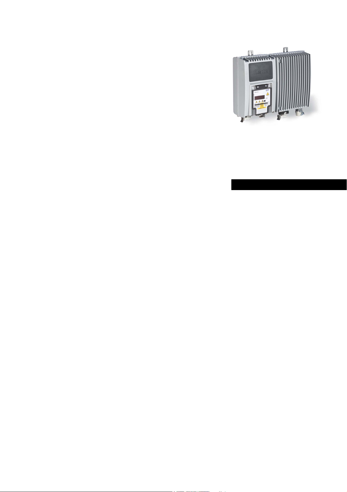
Inverter Drives 8400 protec · Drive-based safety _ _ _ _ _ _ _ _ _ _
E84Dxxxxx...
Software manual EN
Ä.A+0ä
13321015
L
Page 2

Contents
Contents
_ _ _ _ _ _ _ _ _ _ _ _ _ _ _ _ _ _ _ _ _ _ _ _ _ _ _ _ _ _ _ _ _ _ _ _ _ _ _ _ _ _ _ _ _ _ _ _ _ _ _ _ _ _ _ _ _ _ _ _ _ _ _ _
1 About this documentation _ _ _ _ _ _ _ _ _ _ _ _ _ _ _ _ _ _ _ _ _ _ _ _ _ _ _ _ _ _ _ _ _ _ _ _ _ _ _ 4
1.1 Document history _ _ _ _ _ _ _ _ _ _ _ _ _ _ _ _ _ _ _ _ _ _ _ _ _ _ _ _ _ _ _ _ _ _ _ _ _ _ _ _ _ _ _ _ 4
1.2 Conventions used _ _ _ _ _ _ _ _ _ _ _ _ _ _ _ _ _ _ _ _ _ _ _ _ _ _ _ _ _ _ _ _ _ _ _ _ _ _ _ _ _ _ _ _ 5
1.3 Terminology used _ _ _ _ _ _ _ _ _ _ _ _ _ _ _ _ _ _ _ _ _ _ _ _ _ _ _ _ _ _ _ _ _ _ _ _ _ _ _ _ _ _ _ _ 6
1.4 Terms and abbreviations used in drive-based safety _ _ _ _ _ _ _ _ _ _ _ _ _ _ _ _ _ _ _ _ _ _ _ _ _ 7
1.5 Notes used _ _ _ _ _ _ _ _ _ _ _ _ _ _ _ _ _ _ _ _ _ _ _ _ _ _ _ _ _ _ _ _ _ _ _ _ _ _ _ _ _ _ _ _ _ _ _ _ 8
2Introduction _ _ _ _ _ _ _ _ _ _ _ _ _ _ _ _ _ _ _ _ _ _ _ _ _ _ _ _ _ _ _ _ _ _ _ _ _ _ _ _ _ _ _ _ _ _ _ 9
2.1 Functional range of the functional safety (short overview) _ _ _ _ _ _ _ _ _ _ _ _ _ _ _ _ _ _ _ _ _ _ 9
2.2 Function mode of safety engineering _ _ _ _ _ _ _ _ _ _ _ _ _ _ _ _ _ _ _ _ _ _ _ _ _ _ _ _ _ _ _ _ _ 10
2.3 Connection to the application _ _ _ _ _ _ _ _ _ _ _ _ _ _ _ _ _ _ _ _ _ _ _ _ _ _ _ _ _ _ _ _ _ _ _ _ _ 11
2.3.1 "LS_SMInterface" system block _ _ _ _ _ _ _ _ _ _ _ _ _ _ _ _ _ _ _ _ _ _ _ _ _ _ _ _ _ _ _ 12
2.3.1.1 Status information _ _ _ _ _ _ _ _ _ _ _ _ _ _ _ _ _ _ _ _ _ _ _ _ _ _ _ _ _ _ _ 12
2.3.1.2 I/O-Status information _ _ _ _ _ _ _ _ _ _ _ _ _ _ _ _ _ _ _ _ _ _ _ _ _ _ _ _ _ 13
2.3.1.3 Control information _ _ _ _ _ _ _ _ _ _ _ _ _ _ _ _ _ _ _ _ _ _ _ _ _ _ _ _ _ _ 13
2.3.1.4 Transferring the control information to the application _ _ _ _ _ _ _ _ _ _ _ 14
2.3.1.5 Interconnection examples _ _ _ _ _ _ _ _ _ _ _ _ _ _ _ _ _ _ _ _ _ _ _ _ _ _ _ 15
2.4 Parameter setting and configuration _ _ _ _ _ _ _ _ _ _ _ _ _ _ _ _ _ _ _ _ _ _ _ _ _ _ _ _ _ _ _ _ _ _ 18
2.5 Diagnostics & error management _ _ _ _ _ _ _ _ _ _ _ _ _ _ _ _ _ _ _ _ _ _ _ _ _ _ _ _ _ _ _ _ _ _ _ 20
3 Safe configuration _ _ _ _ _ _ _ _ _ _ _ _ _ _ _ _ _ _ _ _ _ _ _ _ _ _ _ _ _ _ _ _ _ _ _ _ _ _ _ _ _ _ _ _ 22
3.1 Change parameter settings _ _ _ _ _ _ _ _ _ _ _ _ _ _ _ _ _ _ _ _ _ _ _ _ _ _ _ _ _ _ _ _ _ _ _ _ _ _ _ 23
3.2 Import/export parameter settings _ _ _ _ _ _ _ _ _ _ _ _ _ _ _ _ _ _ _ _ _ _ _ _ _ _ _ _ _ _ _ _ _ _ _ 24
3.3 Plausibility check _ _ _ _ _ _ _ _ _ _ _ _ _ _ _ _ _ _ _ _ _ _ _ _ _ _ _ _ _ _ _ _ _ _ _ _ _ _ _ _ _ _ _ _ 25
3.4 General parameters _ _ _ _ _ _ _ _ _ _ _ _ _ _ _ _ _ _ _ _ _ _ _ _ _ _ _ _ _ _ _ _ _ _ _ _ _ _ _ _ _ _ _ 25
3.4.1 Setting of the safety address _ _ _ _ _ _ _ _ _ _ _ _ _ _ _ _ _ _ _ _ _ _ _ _ _ _ _ _ _ _ _ _ _ 26
3.5 Safety functions _ _ _ _ _ _ _ _ _ _ _ _ _ _ _ _ _ _ _ _ _ _ _ _ _ _ _ _ _ _ _ _ _ _ _ _ _ _ _ _ _ _ _ _ _ 27
3.5.1 Stop functions _ _ _ _ _ _ _ _ _ _ _ _ _ _ _ _ _ _ _ _ _ _ _ _ _ _ _ _ _ _ _ _ _ _ _ _ _ _ _ _ 27
3.5.1.1 Prioritisation _ _ _ _ _ _ _ _ _ _ _ _ _ _ _ _ _ _ _ _ _ _ _ _ _ _ _ _ _ _ _ _ _ _ 27
3.5.1.2 Restart behaviour _ _ _ _ _ _ _ _ _ _ _ _ _ _ _ _ _ _ _ _ _ _ _ _ _ _ _ _ _ _ _ _ 28
3.5.1.3 Emergency stop function (SSE) _ _ _ _ _ _ _ _ _ _ _ _ _ _ _ _ _ _ _ _ _ _ _ _ 29
3.5.1.4 Safe torque off (STO) _ _ _ _ _ _ _ _ _ _ _ _ _ _ _ _ _ _ _ _ _ _ _ _ _ _ _ _ _ _ 29
3.5.1.5 Safe stop 1 (SS1) _ _ _ _ _ _ _ _ _ _ _ _ _ _ _ _ _ _ _ _ _ _ _ _ _ _ _ _ _ _ _ _ 30
3.5.2 Operation mode selection _ _ _ _ _ _ _ _ _ _ _ _ _ _ _ _ _ _ _ _ _ _ _ _ _ _ _ _ _ _ _ _ _ _ 31
3.5.2.1 Operation mode selector (OMS) _ _ _ _ _ _ _ _ _ _ _ _ _ _ _ _ _ _ _ _ _ _ _ _ 31
3.5.2.2 Enable switch (ES) _ _ _ _ _ _ _ _ _ _ _ _ _ _ _ _ _ _ _ _ _ _ _ _ _ _ _ _ _ _ _ 32
3.6 Safety bus _ _ _ _ _ _ _ _ _ _ _ _ _ _ _ _ _ _ _ _ _ _ _ _ _ _ _ _ _ _ _ _ _ _ _ _ _ _ _ _ _ _ _ _ _ _ _ _ 33
3.6.1 PROFIsafe connection _ _ _ _ _ _ _ _ _ _ _ _ _ _ _ _ _ _ _ _ _ _ _ _ _ _ _ _ _ _ _ _ _ _ _ _ 34
3.6.1.1 PROFIsafe output data _ _ _ _ _ _ _ _ _ _ _ _ _ _ _ _ _ _ _ _ _ _ _ _ _ _ _ _ _ 36
3.6.1.2 PROFIsafe input data _ _ _ _ _ _ _ _ _ _ _ _ _ _ _ _ _ _ _ _ _ _ _ _ _ _ _ _ _ _ 38
4 Safety option 20 _ _ _ _ _ _ _ _ _ _ _ _ _ _ _ _ _ _ _ _ _ _ _ _ _ _ _ _ _ _ _ _ _ _ _ _ _ _ _ _ _ _ _ _ _ 41
5 Safety option 30 _ _ _ _ _ _ _ _ _ _ _ _ _ _ _ _ _ _ _ _ _ _ _ _ _ _ _ _ _ _ _ _ _ _ _ _ _ _ _ _ _ _ _ _ _ 42
5.1 Safe inputs _ _ _ _ _ _ _ _ _ _ _ _ _ _ _ _ _ _ _ _ _ _ _ _ _ _ _ _ _ _ _ _ _ _ _ _ _ _ _ _ _ _ _ _ _ _ _ _ 42
6 Safe parameter transfer _ _ _ _ _ _ _ _ _ _ _ _ _ _ _ _ _ _ _ _ _ _ _ _ _ _ _ _ _ _ _ _ _ _ _ _ _ _ _ _ _ 44
6.1 Send safe data _ _ _ _ _ _ _ _ _ _ _ _ _ _ _ _ _ _ _ _ _ _ _ _ _ _ _ _ _ _ _ _ _ _ _ _ _ _ _ _ _ _ _ _ _ _ 45
6.2 Read safe data from device _ _ _ _ _ _ _ _ _ _ _ _ _ _ _ _ _ _ _ _ _ _ _ _ _ _ _ _ _ _ _ _ _ _ _ _ _ _ _ 46
6.3 Write parameter set into file _ _ _ _ _ _ _ _ _ _ _ _ _ _ _ _ _ _ _ _ _ _ _ _ _ _ _ _ _ _ _ _ _ _ _ _ _ _ 47
6.4 Read parameter set out of file _ _ _ _ _ _ _ _ _ _ _ _ _ _ _ _ _ _ _ _ _ _ _ _ _ _ _ _ _ _ _ _ _ _ _ _ _ 47
6.5 General reset of device _ _ _ _ _ _ _ _ _ _ _ _ _ _ _ _ _ _ _ _ _ _ _ _ _ _ _ _ _ _ _ _ _ _ _ _ _ _ _ _ _ 48
6.6 Password management _ _ _ _ _ _ _ _ _ _ _ _ _ _ _ _ _ _ _ _ _ _ _ _ _ _ _ _ _ _ _ _ _ _ _ _ _ _ _ _ _ 49
2 Lenze · 8400 protec · Drive-based safety · Software Manual · DMS 2.4 EN · 05/2013 · TD05
Page 3

Contents
_ _ _ _ _ _ _ _ _ _ _ _ _ _ _ _ _ _ _ _ _ _ _ _ _ _ _ _ _ _ _ _ _ _ _ _ _ _ _ _ _ _ _ _ _ _ _ _ _ _ _ _ _ _ _ _ _ _ _ _ _ _ _ _
7 Parameter reference _ _ _ _ _ _ _ _ _ _ _ _ _ _ _ _ _ _ _ _ _ _ _ _ _ _ _ _ _ _ _ _ _ _ _ _ _ _ _ _ _ _ _ 50
7.1 Parameter list _ _ _ _ _ _ _ _ _ _ _ _ _ _ _ _ _ _ _ _ _ _ _ _ _ _ _ _ _ _ _ _ _ _ _ _ _ _ _ _ _ _ _ _ _ _ 50
7.2 Table of attributes _ _ _ _ _ _ _ _ _ _ _ _ _ _ _ _ _ _ _ _ _ _ _ _ _ _ _ _ _ _ _ _ _ _ _ _ _ _ _ _ _ _ _ _ 65
Index _ _ _ _ _ _ _ _ _ _ _ _ _ _ _ _ _ _ _ _ _ _ _ _ _ _ _ _ _ _ _ _ _ _ _ _ _ _ _ _ _ _ _ _ _ _ _ _ _ _ _ 67
Lenze · 8400 protec · Drive-based safety · Software Manual · DMS 2.4 EN · 05/2013 · TD05 3
Page 4

1 About this documentation
1.1 Document history
_ _ _ _ _ _ _ _ _ _ _ _ _ _ _ _ _ _ _ _ _ _ _ _ _ _ _ _ _ _ _ _ _ _ _ _ _ _ _ _ _ _ _ _ _ _ _ _ _ _ _ _ _ _ _ _ _ _ _ _ _ _ _ _
1 About this documentation
The manual contains the complete information on the application as directed of the decentralised
controllers 8400
protec with drive-based safety (safety option 20 and 30).
Please read the mounting instructions supplied with the controller before you start
working!
The mounting instructions contain safety instructions that must be observed!
Target group
This manual is intended for all persons who want to parameterise, configure, and diagnose the
integrated safety systems in controllers of the 8400
engineering software.
Validity
The information given in this manual applies to 8400 protec controllers with the following
nameplate data:
protec series with the L-force »Engineer«
Product series Type designation From software version
8400 protec StateLine
with safety option 20 E84DSWTxxxxxxN0xxx-xKxxS 01.00
with safety option 30 E84DSWTxxxxxxN0xxx-xLxxS 01.00
8400 protec HighLine
Screenshots/application examples
All screenshots provided in this documentation are application examples. Depending on the
software version of the controller and the version of the installed »Engineer« software, the
screenshots in this documentation may differ from the representation in the »Engineer«.
with safety option 20 E84DHWTxxxxxxN0xxx-xKxxS 01.00
with safety option 30 E84DHWTxxxxxxN0xxx-xLxxS 01.00
Tip!
Information and tools for Lenze products are provided in the download area at
http://www.Lenze.com
1.1 Document history
Download
Version Description
2.4 05/2013 TD05 Corrections
2.3 01/2013 TD05 Converted to new layout
2.2 02/2010 TD14 Corrections
2.1 11/2009 TD14 Corrections
2.0 09/2009 TD14 Corrections and extension by safety option SO20
1.0 05/2009 TD14 First edition
4
Lenze · 8400 protec · Drive-based safety · Software Manual · DMS 2.4 EN · 05/2013 · TD05
Page 5

1 About this documentation
1.2 Conventions used
_ _ _ _ _ _ _ _ _ _ _ _ _ _ _ _ _ _ _ _ _ _ _ _ _ _ _ _ _ _ _ _ _ _ _ _ _ _ _ _ _ _ _ _ _ _ _ _ _ _ _ _ _ _ _ _ _ _ _ _ _ _ _ _
1.2 Conventions used
This manual uses the following conventions to distinguish between different types of information:
Type of information Writing Examples/notes
Spelling of numbers
Decimal separators Point The decimal point is generally used.
For example: 1234.56
Text
Version information Blue text colour Information that is only valid for or from a certain software
Program name » « The Lenze »Engineer« PC software ...
Window italics The Message window ... / The Options dialog box...
Variable name By setting bEnable to TRUE...
Control element bold The OK button... / The Copy command... / The Properties
Sequence of menu
commands
Shortcut <bold> Press <F1> to open the online help.
Hyperlink Underlined
Icons
Page reference ( 5) Optically highlighted reference to another page. In this
Step-by-step instructions
version of the controller is marked accordingly in this
manual.
Example: This function extension is available from software
version V3.0!
tab... / The Name input field...
If the execution of a function requires several commands,
the individual commands are separated by an arrow: Select
Open to...
File
If a command requires a combination of keys, a "+" is placed
between the key symbols:
Use <Shift>+<ESC> to...
Optically highlighted reference to another topic. In this
documentation activated by mouse-click.
documentation activated by mouse-click.
Step-by-step instructions are indicated by a pictograph.
Information that is only valid for or as from a certain software version of the controller are marked
accordingly in this manual.
Lenze · 8400 protec · Drive-based safety · Software Manual · DMS 2.4 EN · 05/2013 · TD05 5
Page 6

1 About this documentation
1.3 Terminology used
_ _ _ _ _ _ _ _ _ _ _ _ _ _ _ _ _ _ _ _ _ _ _ _ _ _ _ _ _ _ _ _ _ _ _ _ _ _ _ _ _ _ _ _ _ _ _ _ _ _ _ _ _ _ _ _ _ _ _ _ _ _ _ _
1.3 Terminology used
Term Meaning
»Engineer« Lenze PC software which supports you in "engineering" (parameterisation,
Application block Block for a technology application (e.g. actuating drive - speed)
Code Parameter used for controller parameterisation or monitoring.
Display codes Parameter that displays the current status or value of a system block input/
FB Editor Function block editor
Function block General designation of a function block for free interconnection (only
Lenze setting This setting is the default factory setting of the device.
Port block Block for implementing the process data transfer via a fieldbus
Subcode If a code contains several parameters, these are stored in the "subcodes".
System block System blocks provide interfaces to basic functions and to the hardware of
diagnostics and configuration) throughout the whole life cycle, i.e. from
planning to maintenance of the commissioned machine.
A technology application is a drive solution based on the experience and
know-how of Lenze in which function blocks interconnected to a signal flow
form the basis for implementing typical drive tasks.
The term is usually called "index".
output.
Graphical interconnection tool which is provided for FB interconnections in
the »Engineer« on the FB editor tab and by means of which the applications
integrated in the drive can also be reconfigured and extended by individual
functions.
HighLine).
A function block can be compared with an integrated circuit that contains a
certain control logic and delivers one or several values when being executed.
• Each function block has a unique identifier (the instance name) and a
processing number which defines the position at which the function
block is calculated during the task cycle.
This Manual uses a slash "/" as a separator between code and subcode
(e.g. "C00118/3").
The term is usually called "subindex".
the controller in the FB editor of the »Engineer« (e.g. to the digital inputs).
6
Lenze · 8400 protec · Drive-based safety · Software Manual · DMS 2.4 EN · 05/2013 · TD05
Page 7

1 About this documentation
1.4 Terms and abbreviations used in drive-based safety
_ _ _ _ _ _ _ _ _ _ _ _ _ _ _ _ _ _ _ _ _ _ _ _ _ _ _ _ _ _ _ _ _ _ _ _ _ _ _ _ _ _ _ _ _ _ _ _ _ _ _ _ _ _ _ _ _ _ _ _ _ _ _ _
1.4 Terms and abbreviations used in drive-based safety
Abbreviation Meaning
24O 24-V voltage supply for non-safe feedback
OFF state Signal state of the sensors when they are activated or respond
DO Non-safe feedback output
ON state Signal state of the sensors in normal operation
F-PLC Safety PLC
GSE File with device-specific data for establishing the PROFIBUS communication
GSDML File with device-specific data for establishing the PROFINET communication
Cat. Category according to EN 954-1 (valid until 30 November 2009)
Optocoupler supply Supply of optocouplers to control the driver
OSSD Output Signal Switching Device, tested signal output
PELV Protective extra low voltage
PL Performance Level according to EN ISO 13849-1
PM P/N switching signal paths
PP P/P switching signal paths
PS PROFIsafe
PWM Pulse width modulation
S bus Safety bus
SD-In Safe input (Safe Digital Input)
SD-Out Safe output (Safe Digital Output)
SELV Safety extra low voltage
SIA, SIB Safe input, channel A or channel B
SIL Safety Integrity Level according to IEC 61508
SO integrated safety option
Abbreviation Safety function
AIE Error acknowledgement (Acknowledge in Error)
AIS Restart acknowledgement (Acknowledge in Stop)
ES Safe enable switch (Enable Switch)
OMS Operation mode selector
SS1 Safe stop 1
SSE Emergency stop (Safe Stop Emergency)
STO Safe torque off
Formerly: Safe standstill
Lenze · 8400 protec · Drive-based safety · Software Manual · DMS 2.4 EN · 05/2013 · TD05 7
Page 8

1 About this documentation
1.5 Notes used
_ _ _ _ _ _ _ _ _ _ _ _ _ _ _ _ _ _ _ _ _ _ _ _ _ _ _ _ _ _ _ _ _ _ _ _ _ _ _ _ _ _ _ _ _ _ _ _ _ _ _ _ _ _ _ _ _ _ _ _ _ _ _ _
1.5 Notes used
The following signal words and symbols are used in this documentation to indicate dangers and
important information:
Safety instructions
Layout of the safety instructions:
Danger!
(characterises the type and severity of danger)
Note
(describes the danger and gives information about how to prevent dangerous
situations)
Pictograph Signal word Meaning
Danger! Danger of personal injury through dangerous electrical voltage
Danger! Danger of personal injury through a general source of danger
Stop! Danger of property damage
Application notes
Pictograph Signal word Meaning
Note! Important note to ensure trouble-free operation
Reference to an imminent danger that may result in death or serious personal
injury if the corresponding measures are not taken.
Reference to an imminent danger that may result in death or serious personal
injury if the corresponding measures are not taken.
Reference to a possible danger that may result in property damage if the
corresponding measures are not taken.
Tip! Useful tip for easy handling
Reference to another documentation
8
Lenze · 8400 protec · Drive-based safety · Software Manual · DMS 2.4 EN · 05/2013 · TD05
Page 9

2Introduction
2.1 Functional range of the functional safety (short overview)
_ _ _ _ _ _ _ _ _ _ _ _ _ _ _ _ _ _ _ _ _ _ _ _ _ _ _ _ _ _ _ _ _ _ _ _ _ _ _ _ _ _ _ _ _ _ _ _ _ _ _ _ _ _ _ _ _ _ _ _ _ _ _ _
2 Introduction
The safety concept of the decentralised frequency inverters 8400 protec provide three safety
options depending on the device version.
Safety option 10 (SO10):
• The drive-based safety implemented in the inverter permits to connect external safety
components, e.g. passive sensors. Active sensors with self-testing signals can be directly
connected without using further components.
Safety option 20 (SO20):
• The drive is switched off safely by a higher-level safety PLC via PROFIsafe/PROFINET.
Safety option 30 (SO30):
• The safe disconnection can both be carried out by a higher-level safety PLC via PROFIsafe/
PROFINET and through the connection of active or passive sensors.
Note!
Safety options 20 and 30 can be parameterised via the »Engineer«.
The motion functions are continued to be executed by the controller. The drive-based
safety monitors the safe compliance with the limit values. When the limit values are
exceeded, the drive-based safety starts the control functions according to EN 60204-1
directly in the controller.
The safety functions are suitable for applications according to IEC 61508 to SIL 3 and
achieve the performance level (PL) e according to EN ISO 13849-1.
The requirements of the EN 954-1 standard which was valid until 30 November 2009 are
fulfilled for safety option 10 to control category 4 and for safety option 20 and 30 to
control category 3.
Detailed information on technical data and electrical installation can be found in the
mounting instructions for the 8400 protec.
2.1 Functional range of the functional safety (short overview)
Safety option Safety function Safety bus
STO SS1 SSE OMS ES
Safety option 10
Safety option 20
Safety option 30
PROFINET
Lenze · 8400 protec · Drive-based safety · Software Manual · DMS 2.4 EN · 05/2013 · TD05 9
Page 10
2Introduction
M
SO
PWM
µC
PC
3x
3x
Xx
2.2 Function mode of safety engineering
_ _ _ _ _ _ _ _ _ _ _ _ _ _ _ _ _ _ _ _ _ _ _ _ _ _ _ _ _ _ _ _ _ _ _ _ _ _ _ _ _ _ _ _ _ _ _ _ _ _ _ _ _ _ _ _ _ _ _ _ _ _ _ _
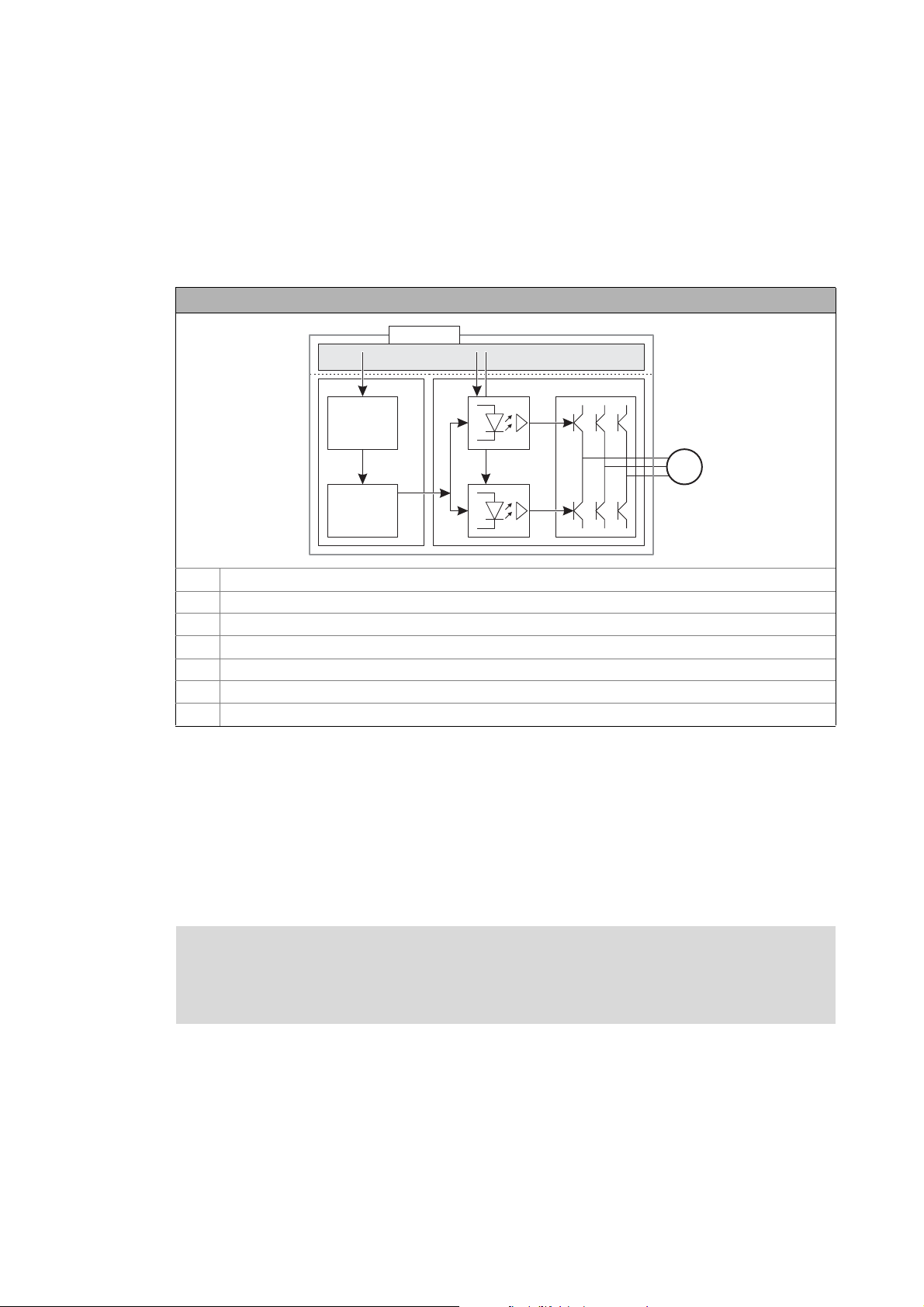
2.2 Function mode of safety engineering
Disconnecting paths
The transmission of the pulse width modulation is safely (dis-)connected by the drive-based safety.
Hence the drivers do not create a rotating field. The motor is safely switched to torqueless operation
(STO).
Disconnecting paths of the drive-based safety
SO Safety option
xx Control terminals of the safety option 10 and 30 (M12 circular connector)
C Control section
μC Microcontroller
PWM Pulse width modulation
PPower section
M Motor
Safety status
When the controller is switched off by the safety system, it is changed to the "Safe torque off active"
status
• "Drive is torque-free" is entered in the logbook.
• C00155 (Bit 10 = 1) displays "Safe torque off active".
Fail-safe status
Note!
If internal errors of the safety system are detected, the motor is safely switched to
torqueless operation (fail-safe state).
10
Lenze · 8400 protec · Drive-based safety · Software Manual · DMS 2.4 EN · 05/2013 · TD05
Page 11

2Introduction
2.3 Connection to the application
_ _ _ _ _ _ _ _ _ _ _ _ _ _ _ _ _ _ _ _ _ _ _ _ _ _ _ _ _ _ _ _ _ _ _ _ _ _ _ _ _ _ _ _ _ _ _ _ _ _ _ _ _ _ _ _ _ _ _ _ _ _ _ _
2.3 Connection to the application
When a safety function is requested, the safety technology activates the corresponding safe
monitoring function. The only standstill function executed directly is the "safe torque off" (STO)
function. All other safety functions require a controller action which is safely monitored.
Note!
The execution of the corresponding action (e.g. braking, braking to standstill, holding
the standstill position) requires an appropriate application interconnection which must
be provided by the operator!
"LS_SMInterface" system block
The LS_SMInterface system block in the function block editor of the »Engineer« serves to transmit
the control and status information from the safety system to the application. ( 12)
Basic procedure
1. Activation of the safety function (e.g. SS1 - safe stop 1).
• Monitoring starts.
2. Via a control word, the safety system transmits the information to the controller that the safety
function has been activated.
3. The application evaluates the control word and starts the required motion sequence (e.g.
braking).
Internal communication
The drive-based safety system and the standard device communicate via an internal interface.
Note!
If the communication to the controller is interrupted, e.g. by switching off the controller,
the safety system responds with the following actions:
• Error stop with STO is activated.
• Error message "Warning" is transmitted.
• The LED "S-Error" on the front of the controller is on.
The required error acknowledgement (AIE) is possible via the safety bus and with SO30
via the error acknowledgement input (plug X62).
Further information can be found in chapter "Diagnostics & error management
" ( 20).
Lenze · 8400 protec · Drive-based safety · Software Manual · DMS 2.4 EN · 05/2013 · TD05 11
Page 12
2Introduction
Z6WDWH
Z,26WDWH
Z&RQWURO
E3RZHU6WDJH(QDEOH
Z0RGXOH,'
/6B60,QWHUIDFH
6DIHW\
RSWLRQ
2.3 Connection to the application
_ _ _ _ _ _ _ _ _ _ _ _ _ _ _ _ _ _ _ _ _ _ _ _ _ _ _ _ _ _ _ _ _ _ _ _ _ _ _ _ _ _ _ _ _ _ _ _ _ _ _ _ _ _ _ _ _ _ _ _ _ _ _ _
2.3.1 "LS_SMInterface" system block
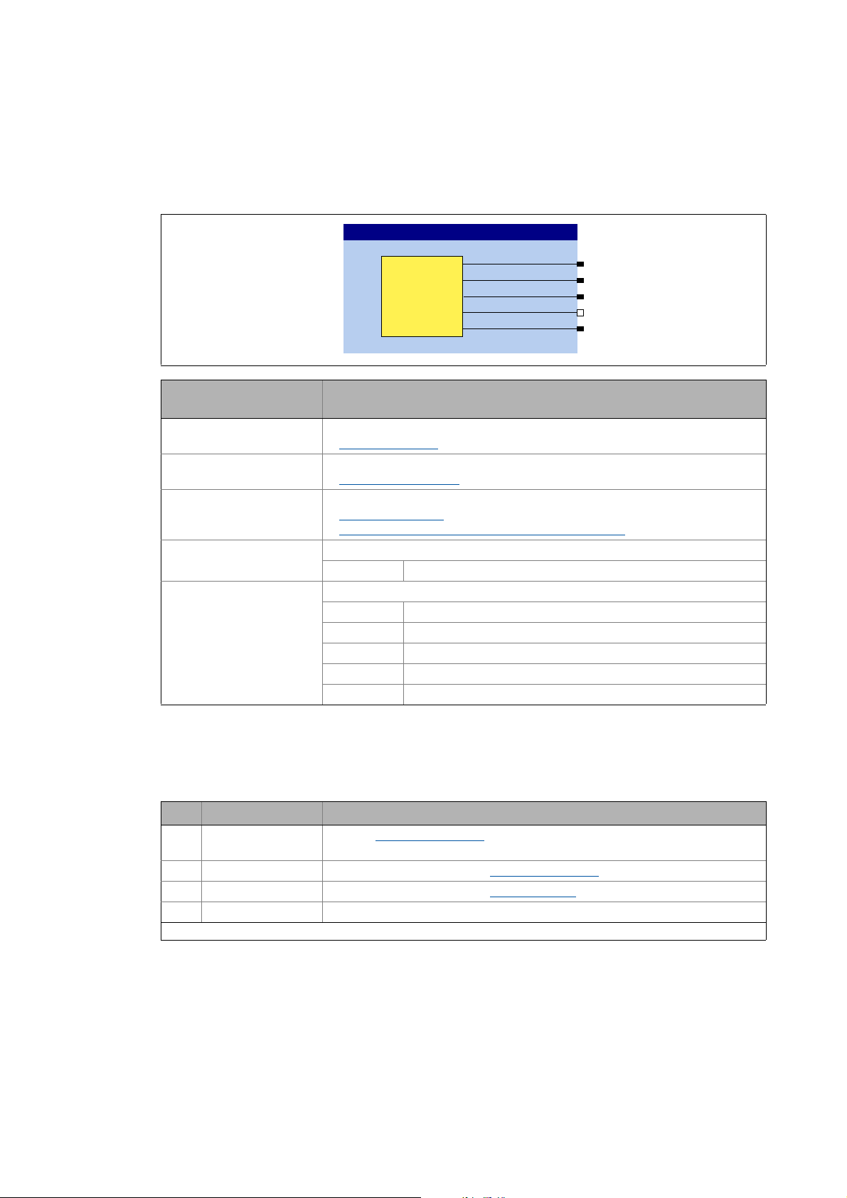
The system block LS_SMInterface is the interface to the integrated safety system in the function
block editor of the »Engineer«.
Output
wState
wIOState
wControl
bPowerStageEnable
wModuleID
2.3.1.1 Status information
The drive-based safety system transmits information about the status of the requested or active
safety functions with the bit coded status signal wState.
Data type
WORD
WORD
WORD
BOOL
WORD
Value/meaning
Bit coded status information of the drive-based safety
Status information
Bit coded I/O information of the drive-based safety
I/O-Status information
Bit coded control information of the drive-based safety
Control information
Transferring the control information to the application
Status signal "Inverter enable"
TRUE Inverter is enabled by the safety system.
ID of the safety system in the controller
0 No safety system available
1 Safety option 10 (SO10):
2 Reserved
3 Safety option 20 (SO20):
4 Safety option 30 (SO30):
( 12)
( 13)
( 13)
( 14)
12
Bit Name Meaning
0STO Function Safe torque off (STO)
3 EC_STO Error stop category 0: Function Safe torque off (STO)
4 EC_SS1 Error stop category 1: Function Safe stop 1 (SS1)
14 Error active Drive-based safety system in error status (trouble or warning).
Unlisted bits are reserved for future extensions!
[2-1] Bit coding of the status signal wState
is active.
• The drive is safely switched to torqueless operation.
is active.
is active.
Lenze · 8400 protec · Drive-based safety · Software Manual · DMS 2.4 EN · 05/2013 · TD05
Page 13
2Introduction
2.3 Connection to the application
_ _ _ _ _ _ _ _ _ _ _ _ _ _ _ _ _ _ _ _ _ _ _ _ _ _ _ _ _ _ _ _ _ _ _ _ _ _ _ _ _ _ _ _ _ _ _ _ _ _ _ _ _ _ _ _ _ _ _ _ _ _ _ _
2.3.1.2 I/O-Status information
The bit-coded wIOState status signal serves to transfer the status the safe inputs and the safe
output:
Bit Name Meaning
0 SD-In1 Sensor input 1 in ON state.
1 SD-In2 Sensor input 1 in ON state.
5 AIS Restart is acknowledged via terminal (negative edge: 10).
6 AIE Error is acknowledged via terminal (negative edge: 10).
8 PS_AIS Restart is acknowledged via safety bus (positive edge: 01).
9 PS_AIE Error is acknowledged via safety bus (positive edge: 01).
Unlisted bits are reserved for future extensions!
[2-2] Bit coding of the wIOState status signal
2.3.1.3 Control information
The bit coded wControl control signal serves to transfer information about requested or active
safety functions. The application in the controller must evaluate the control signal and carry out the
corresponding action.
• It is possible to request/activate several safety functions at the same time.
Bit Name Meaning
0SS1 active Safe stop 1 (SS1)
2ES active Enable switch (ES)
3OMS Operation mode selector (OMS)
4SSE active Emergency stop function (SSE)
• Depending on the parameterisation of the emergency stop function, bit 1 (SS1
active) or bit 0 of the status signal SMI_wState (STO active) is set after the
function has ended.
5 OMS active Special operation is active.
Unlisted bits are reserved for future extensions!
[2-3] Bit coding of the wControl control signal
is active.
function for motion functions in special operations is active.
function for special operations is requested.
is active.
Note!
The application in the controller must evaluate the control signal wControl and carry out
the corresponding action. The execution of the corresponding action (e.g. braking to
standstill) requires an appropriate application interconnection which must be provided
by the operator!
See the following subchapter "Transferring the control information to the application".
( 14)
Lenze · 8400 protec · Drive-based safety · Software Manual · DMS 2.4 EN · 05/2013 · TD05 13
Page 14
2Introduction
2.3 Connection to the application
_ _ _ _ _ _ _ _ _ _ _ _ _ _ _ _ _ _ _ _ _ _ _ _ _ _ _ _ _ _ _ _ _ _ _ _ _ _ _ _ _ _ _ _ _ _ _ _ _ _ _ _ _ _ _ _ _ _ _ _ _ _ _ _
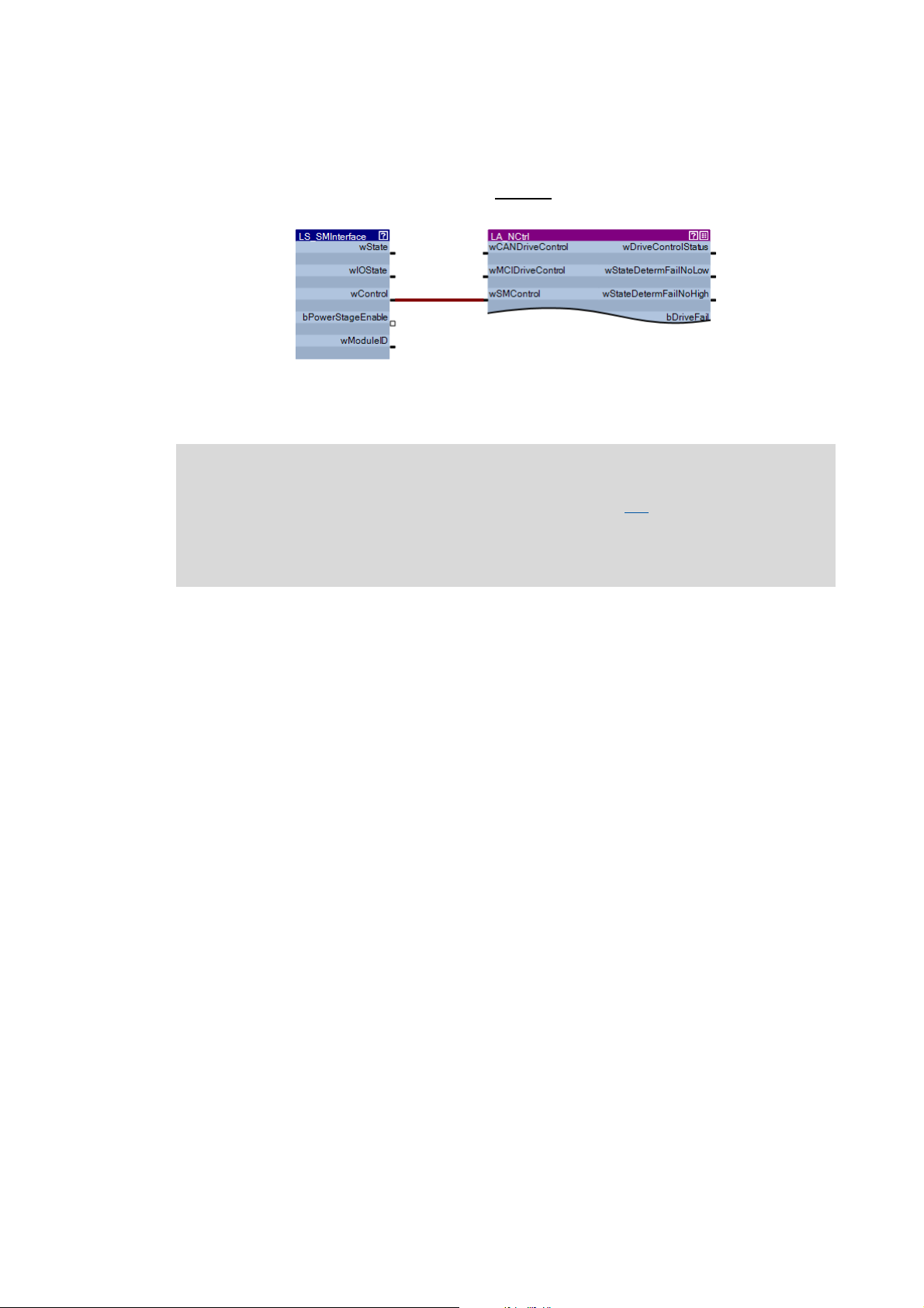
2.3.1.4 Transferring the control information to the application
In the simplest case, you only have to go to the I/O level in the FB editor and connect the wControl
output of the LS_SMInterface system block with the wSMControl input of the application block:
On the application level, the wSMControl input is connected with the motion control kernel. The
motion control kernel evaluates the transmitted control information and activates the required
motion sequence (e.g. braking).
Note!
At present, the motion control kernel only evaluates bit 0 (SS1). When this safety
function is requested, the drive will be decelerated to standstill along the stop ramp set
in C02610/3.
Additional functions are in preparation.
14
Lenze · 8400 protec · Drive-based safety · Software Manual · DMS 2.4 EN · 05/2013 · TD05
Page 15
2Introduction
2.3 Connection to the application
_ _ _ _ _ _ _ _ _ _ _ _ _ _ _ _ _ _ _ _ _ _ _ _ _ _ _ _ _ _ _ _ _ _ _ _ _ _ _ _ _ _ _ _ _ _ _ _ _ _ _ _ _ _ _ _ _ _ _ _ _ _ _ _
2.3.1.5 Interconnection examples
... for decoding the status and control information of the drive-based safety system into single
boolean signals.
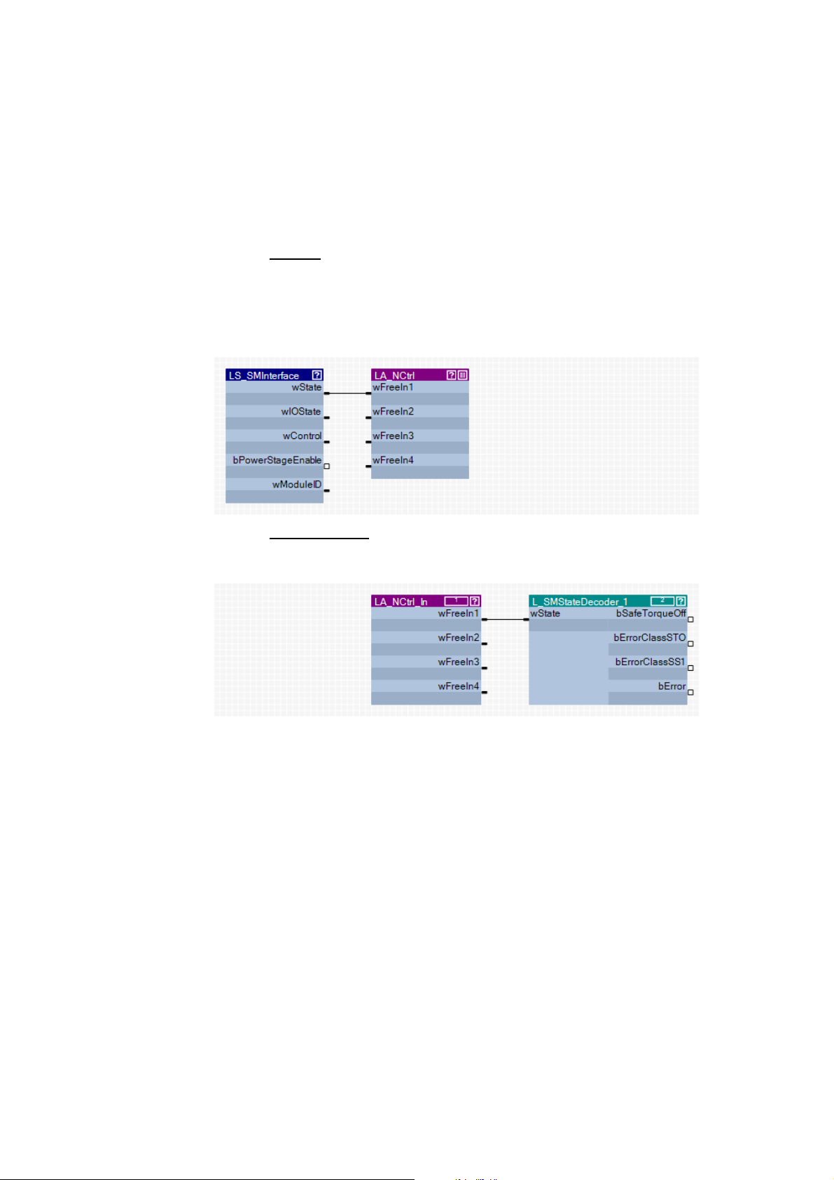
How to decode the status information into single boolean status signals:
1. Go to the I/O level
system block with one of the free inputs wFreeIn1 ... wFreeIn4 of the application block.
• In the following example, the wState output is connected with the free wFreeIn1 input
of the LA_NCtrl application block on the I/O level.
• For a better overview, all other connections of the LA_NCtrl application block are not
shown here.
in the FB editor and connect the wState output of the LS_SMInterface
2. Go to the application level
input of the L_SMStateDecoder_1 function block.
•The free inputs wFreeIn1 ... wFreeIn4 are outputs on the application level.
The L_SMStateDecoder_1 function block decodes the status signal assigned to the wState
input into single boolean status signals for further use in the FB interconnection.
and connect the selected free input wFreeIn with the wState
Lenze · 8400 protec · Drive-based safety · Software Manual · DMS 2.4 EN · 05/2013 · TD05 15
Page 16
2Introduction
2.3 Connection to the application
_ _ _ _ _ _ _ _ _ _ _ _ _ _ _ _ _ _ _ _ _ _ _ _ _ _ _ _ _ _ _ _ _ _ _ _ _ _ _ _ _ _ _ _ _ _ _ _ _ _ _ _ _ _ _ _ _ _ _ _ _ _ _ _
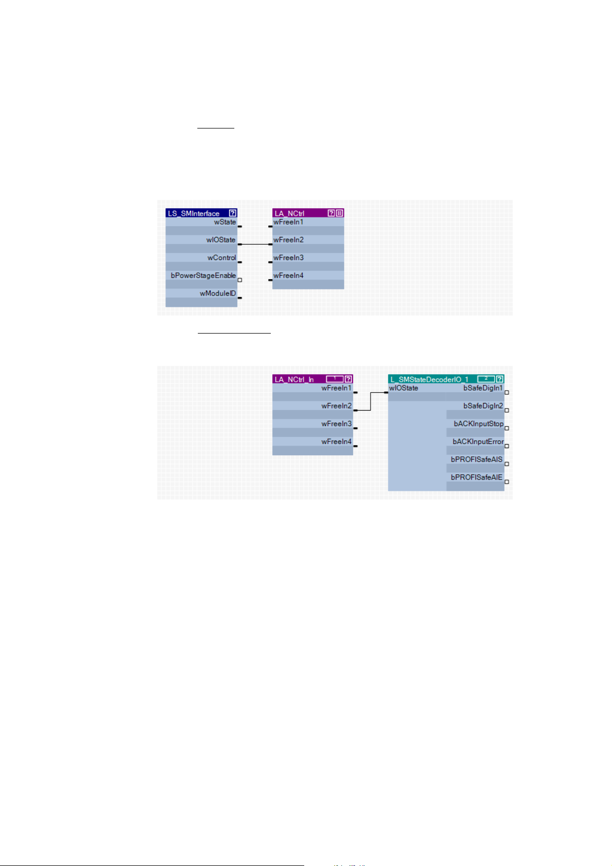
How to decode the I/O status information into single boolean status signals:
1. Go to the I/O level
system block with one of the free inputs wFreeIn1 ... wFreeIn4 of the application block.
• In the following example, the wIOState output is connected with the free wFreeIn2 input
of the LA_NCtrl application block on the I/O level.
• For a better overview, all other connections of the LA_NCtrl application block are not
shown here.
2. Go to the application level
input of the L_SMStateDecoderIO_1 function block.
•The free inputs wFreeIn1 ... wFreeIn4 are outputs on the application level.
in the FB editor and connect the wIOState output of the LS_SMInterface
and connect the selected free input wFreeIn with the wIOState
The L_SMStateDecoderIO_1 function block decodes the status signal assigned to the
wIOState input into single boolean status signals for further use in the FB interconnection.
16
Lenze · 8400 protec · Drive-based safety · Software Manual · DMS 2.4 EN · 05/2013 · TD05
Page 17
2Introduction
2.3 Connection to the application
_ _ _ _ _ _ _ _ _ _ _ _ _ _ _ _ _ _ _ _ _ _ _ _ _ _ _ _ _ _ _ _ _ _ _ _ _ _ _ _ _ _ _ _ _ _ _ _ _ _ _ _ _ _ _ _ _ _ _ _ _ _ _ _
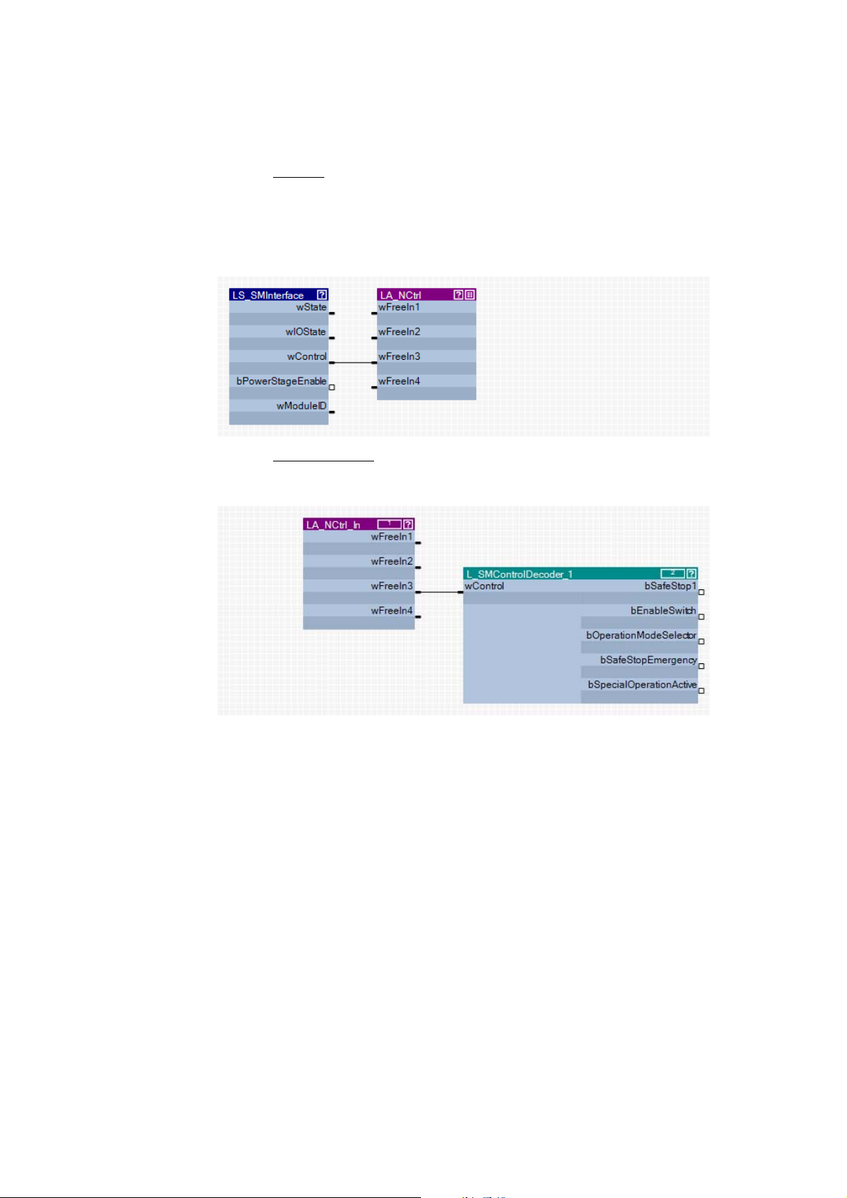
How to decode the control information into single boolean control signals:
1. Go to the I/O level
system block with one of the free inputs wFreeIn1 ... wFreeIn4 of the application block.
• In the following example, the wControl output is connected with the free wFreeIn3 input
of the LA_NCtrl application block on the I/O level.
• For a better overview, all other connections of the LA_NCtrl application block are not
shown here.
2. Go to the application level
on this level, with the wControl input of the L_SMControlDecoder_1 function block.
•The free inputs wFreeIn1 ... wFreeIn4 are outputs on the application level.
in the FB editor and connect the wControl output of the LS_SMInterface
and connect the selected free input wFreeIn, which is an output
The L_SMControlDecoder_1 function block decodes the control signal assigned to the
wControl input into single boolean control signals for further use in the FB interconnection.
Lenze · 8400 protec · Drive-based safety · Software Manual · DMS 2.4 EN · 05/2013 · TD05 17
Page 18
2Introduction
2.4 Parameter setting and configuration
_ _ _ _ _ _ _ _ _ _ _ _ _ _ _ _ _ _ _ _ _ _ _ _ _ _ _ _ _ _ _ _ _ _ _ _ _ _ _ _ _ _ _ _ _ _ _ _ _ _ _ _ _ _ _ _ _ _ _ _ _ _ _ _
2.4 Parameter setting and configuration
Note!
Safety-relevant parameters can only be transmitted to the drive-based safety system via
safe parameter setting with the »Engineer«.
The parameter set is stored in the memory module and in the drive-based safety system
with a unique module ID, which must correspond to the effective safety address in the
drive-based safety system.
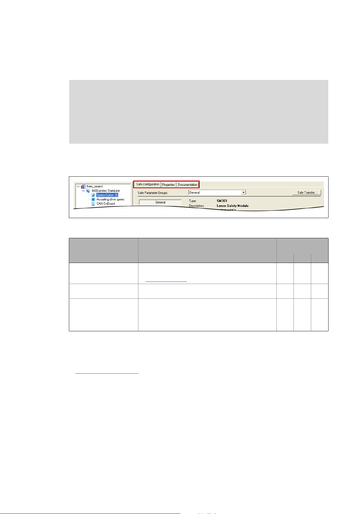
If you select the safety option in the project view of the »Engineer«, different tabs for the safety
system are available in the workspace. The following illustration shows the tabs for safety
option
30:
[2-1] Tabs of the integrated safety system (here as an example for safety option 30)
Tab Information available for
Safe configuration This tab serves to make the safe configuration of the drive-
Features This tab displays general information on the safety system,
Documentation This tab serves to add notes and electronic documents to the
Safe parameter transfer
By clicking Safe Transfer on the Safe configuration tab, the Safe Transfer dialog box opens which
provides the function for a safe parameter transfer.
Safe parameter transfer ( 44)
based safety.
Safe configuration
e.g. product name, version, etc.
drive-based safety system.
• Detailed information on adding documentations can be
found in the »Engineer« documentation in chapter
"Project structure".
( 22)
safety soption
10 20 30
18
Lenze · 8400 protec · Drive-based safety · Software Manual · DMS 2.4 EN · 05/2013 · TD05
Page 19

2Introduction
2.4 Parameter setting and configuration
_ _ _ _ _ _ _ _ _ _ _ _ _ _ _ _ _ _ _ _ _ _ _ _ _ _ _ _ _ _ _ _ _ _ _ _ _ _ _ _ _ _ _ _ _ _ _ _ _ _ _ _ _ _ _ _ _ _ _ _ _ _ _ _
Service status
If you request the "Send safe data to device" function in the Safe Transfer dialog box via the Send
button, the drive-based safety system changes to the "Service status" which is required for a safe
parameter setting.
Send safe data ( 45)
The service status means:
• The standard stop is active and the drive is safely switched to torqueless operation (STO).
• With safety option 30, the safe inputs are evaluated as OFF state.
• The communication via safety bus is - if possible - active, but passivated.
Note!
• The service status is also active if the parameter set in the memory module does not
correspond to the parameter set in the drive-based safety system during the
initialisation.
• The service status can be exited by reinitialising the drive-based safety system, i.e. the
communication via the safety bus is interrupted.
Supported interfaces for a safe parameter setting
A safe parameter setting with the »Engineer« is supported via the following interfaces:
• Diagnostic interface X70
• CANopen system bus interface
Lenze · 8400 protec · Drive-based safety · Software Manual · DMS 2.4 EN · 05/2013 · TD05 19
Page 20
2Introduction
',
',
','2
','2
',
',
5'<
(55
96
%UDNH
%865'<
%86(55
/LQN
/LQN
66WDWH
6(UURU
6$FNQZ
6(QDEOH
'59
6WDWXV &RP 6DIHW\ ,2 ,2
2.5 Diagnostics & error management
_ _ _ _ _ _ _ _ _ _ _ _ _ _ _ _ _ _ _ _ _ _ _ _ _ _ _ _ _ _ _ _ _ _ _ _ _ _ _ _ _ _ _ _ _ _ _ _ _ _ _ _ _ _ _ _ _ _ _ _ _ _ _ _
2.5 Diagnostics & error management
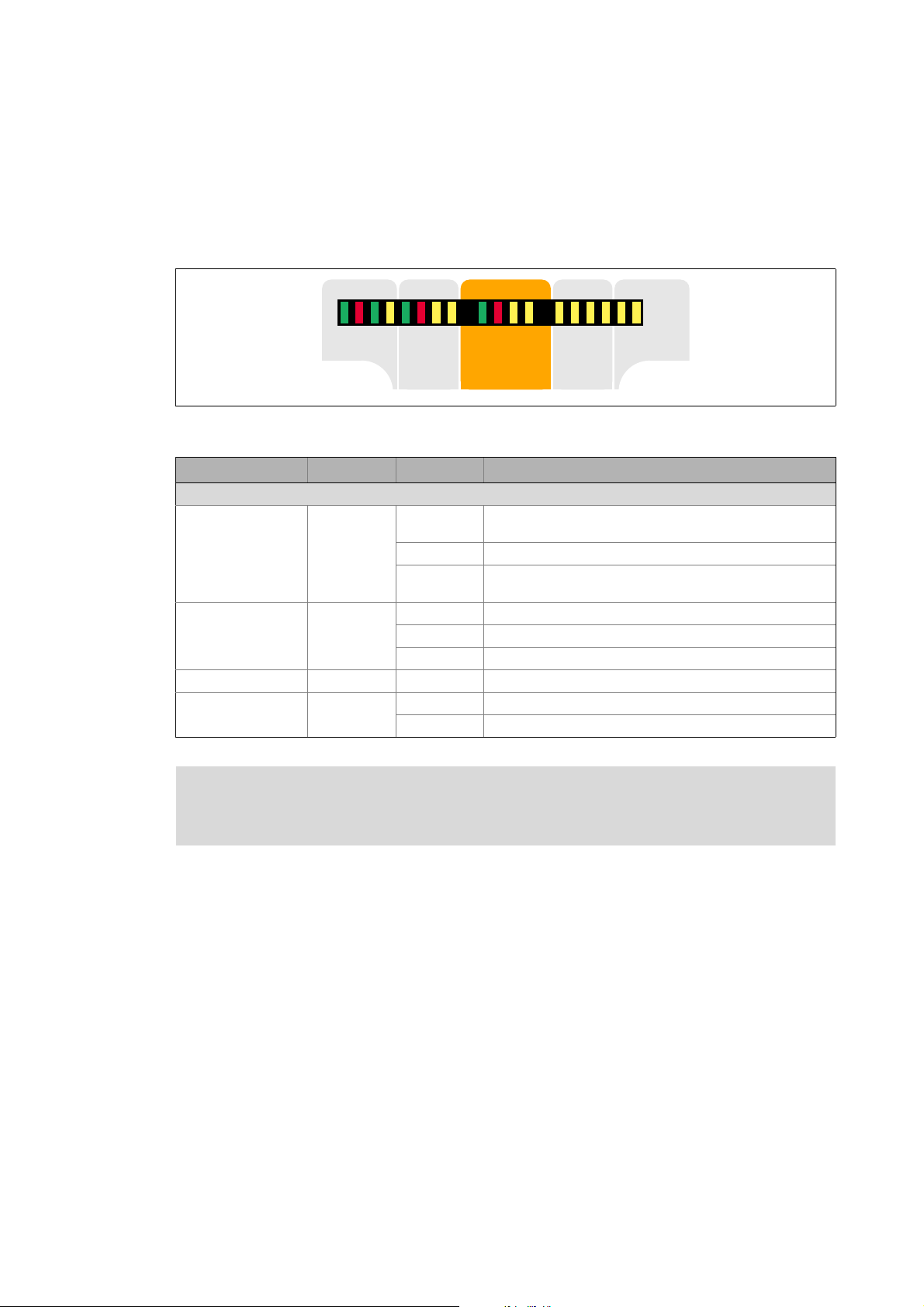
LED display
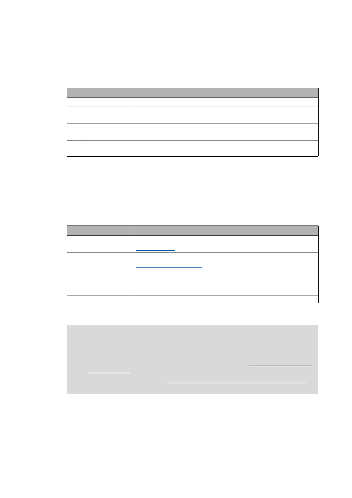
In the "Safety" field in the middle of the LED display on the front of the controller you will get
information on the status of the drive-based safety system:
[2-2] LED display on the front of the controller
Labelling Colour Status Description
LED status displays for the integrated safety system
S-State green off Communication between standard device and safety system
blinking Integrated safety system is in the service status
on Communication between standard device and safety system
S-Error red off Error-free operation
blinking Integrated safety system is not accepted by standard device
S-Acknw yellow on Parameter set acceptance must be acknowledged
S-Enable yellow blinking Safety function active (non-safe display)
on Warning/fault/error
on Controller enabled
is not possible
has been established
Note!
The status of safety option 10 is only indicated via the "S-Enable" LED display.
20
Lenze · 8400 protec · Drive-based safety · Software Manual · DMS 2.4 EN · 05/2013 · TD05
Page 21

2Introduction
2.5 Diagnostics & error management
_ _ _ _ _ _ _ _ _ _ _ _ _ _ _ _ _ _ _ _ _ _ _ _ _ _ _ _ _ _ _ _ _ _ _ _ _ _ _ _ _ _ _ _ _ _ _ _ _ _ _ _ _ _ _ _ _ _ _ _ _ _ _ _
Error states
Detected errors or maloperation of the drive are assigned to error states with definite responses.
The response can be co-ordinated with the complete drive via the error states.
Features Error status
System error Fault Warning
Event Fatal internal error Error Monitoring function
LED "S_Error" On On On
State of the drive-based
safety system
The control category
according to EN 954-1...
Response The motor is immediately
Acknowledgement after
event has been
eliminated
Lockout (CPU stopped) Error status Normal operation
... has been abandoned ... has not been abandoned
safely switched to torqueless
operation via
•STO
• Switching off and then on
again of the 24-V supply at
the safety module
The motor is immediately safely switched to torqueless
operation via
•STO
or shutdown via
• SS1 (parameterisable)
• Error acknowledgement (AIE) plug X62 (positive
signal pulse with a signal duration of 0.3 ... 10 s)
• Error acknowledgement (AIE) via safety bus (bit
"PS_AIE")
• Switching off and then on again of the 24-V supply
at the safety module
Note!
If the system error still occurs after switching the supply voltage, please contact the
Lenze service!
Error in PROFIsafe communication
When PROFIsafe is used as safety bus:
• If errors occur in the PROFIsafe communication, the data are passivated by the PROFIsafe driver.
• After the PROFIsafe communication is reinitialised, the drive reenabled if no standstill function
has been selected.
• Events which cause an error status are sent as a diagnostic telegram via the safety bus.
Logbook
The logbook function integrated in the controller records important events in the system in
chronological order, including error states of the drive-based safety system.
Tip!
When an online connection has been established, the logbook can be displayed in the
»Engineer« via the Logbook button on the Diagnostic tab for the controller.
Detailed information on the logbook can be found in the Online Help for the controller.
Lenze · 8400 protec · Drive-based safety · Software Manual · DMS 2.4 EN · 05/2013 · TD05 21
Page 22

3 Safe configuration
_ _ _ _ _ _ _ _ _ _ _ _ _ _ _ _ _ _ _ _ _ _ _ _ _ _ _ _ _ _ _ _ _ _ _ _ _ _ _ _ _ _ _ _ _ _ _ _ _ _ _ _ _ _ _ _ _ _ _ _ _ _ _ _
3 Safe configuration
The drive-based safety system can be safely configured in the »Engineer« on the Safe configuration
tab for the SM301 safety module
[3-1] Example: Safe configuration tab for safety option 30
The parameters of the drive-based safety system are divided into different groups according to their
functions.
• A group is selected via the Parameter groups list field.
• Some parameter groups are divided into functional subgroups for a better overview which can
be selected via the buttons on the left.
• General parameters
• Safe inputs
(Safe inputs SD-In1 and SD-In2 are only available in connection with the safety option 30.)
• Stop functions
• Operation mode selection
• Safety bus
• In the parameter list all parameters of the parameter group/subgroup selected are displayed.
•The Value field serves to change the corresponding parameter value.
Change parameter settings
•The context menu (right mouse button) provides functions for the import/export of the
parameter settings.
Import/export parameter settings
( 42)
( 33)
( 25)
( 27)
( 31)
( 23)
( 24)
Tip!
If you put the mouse pointer over a parameter, further information on the parameter will
be displayed in a pop-up window.
If you select the entry "All parameters" in the Parameter groups list field, all parameters of
the drive-based safety system are displayed on the tab.
The FilePrint command in the »Engineer« menu bar serves to print all parameter settings
of the drive-based safety system for the purpose of documentation.
22 Lenze · 8400 protec · Drive-based safety · Software Manual · DMS 2.4 EN · 05/2013 · TD05
Page 23

3 Safe configuration
3.1 Change parameter settings
_ _ _ _ _ _ _ _ _ _ _ _ _ _ _ _ _ _ _ _ _ _ _ _ _ _ _ _ _ _ _ _ _ _ _ _ _ _ _ _ _ _ _ _ _ _ _ _ _ _ _ _ _ _ _ _ _ _ _ _ _ _ _ _
3.1 Change parameter settings
Note!
Changed parameters of the drive-based safety system are not transmitted automatically
to the device, even if an online connection has been established!
The parameter set for the drive-based safety system is only safely transmitted when
clicking the Send button in the Safe transfer dialog box!
Send safe data
How to change a parameter setting:
1. Select the parameter to be changed from the list.
2. Enter the new value into the Value column or select it from the defined options.
• Invalid or impermissible values are displayed in "red" in the input field.
• A selection from the list field may cause a deactivation of parameters which are now
irrelevant due to the selection (marked by a grey background colour).
3. Press <Return key> or click into another box to accept the changed value.
• By pressing the <Esc> key you can cancel the entry.
( 45)
Tip!
The parameter settings of the drive-based safety system can also be displayed in the
»Engineer« parameter list (tab All parameters category Safety option) and on the keypad.
Changes, however, are only possible via the Safe configuration tab!
Lenze · 8400 protec · Drive-based safety · Software Manual · DMS 2.4 EN · 05/2013 · TD05 23
Page 24

3 Safe configuration
3.2 Import/export parameter settings
_ _ _ _ _ _ _ _ _ _ _ _ _ _ _ _ _ _ _ _ _ _ _ _ _ _ _ _ _ _ _ _ _ _ _ _ _ _ _ _ _ _ _ _ _ _ _ _ _ _ _ _ _ _ _ _ _ _ _ _ _ _ _ _
3.2 Import/export parameter settings
For transmitting/copying the parameter settings of the drive-based safety system to other
controllers of the 8400 protec series with an identical safety option, the import/export functions
can be used which are available in the parameter list via the Context menu (right mouse button).
Command in the context menu Information
Import... Import all parameter settings from the file.
Export... Export all parameter settings to the file.
Unlocking Unlock imported parameter settings.
• After the "Import" function has been executed, the imported parameter
settings are protected from change by the user. Only an explicit unlocking
enables a change again.
Import group... Import parameter settings of a group from a file.
• Only possible when selecting a parameter group.
Export group... Export parameter settings of a group to a file.
• Only possible when selecting a parameter group.
Unlock group Unlock imported parameter settings of a group.
• After the "Import group" function has been executed, the imported
parameter settings are protected from change by the user. Only an
explicit unlocking enables a change again.
24
Lenze · 8400 protec · Drive-based safety · Software Manual · DMS 2.4 EN · 05/2013 · TD05
Page 25

3 Safe configuration
3.3 Plausibility check
_ _ _ _ _ _ _ _ _ _ _ _ _ _ _ _ _ _ _ _ _ _ _ _ _ _ _ _ _ _ _ _ _ _ _ _ _ _ _ _ _ _ _ _ _ _ _ _ _ _ _ _ _ _ _ _ _ _ _ _ _ _ _ _
3.3 Plausibility check
Before transmitting the parameter set to the drive-based safety system, a plausibility check always
takes place.
Note!
Only a plausible parameter set can be transmitted to the drive-based safety system
using the "Send safe data" function!
With the Plausibility check... command in the Context menu (right mouse button) of the parameter
list you can start the plausibility check manually, to check the changes made in the parameter
settings with regard to plausibility.
• After the plausibility check a status message indicates whether the plausibility check was
successful.
• If the plausibility check failed, the status message contains the parameters with implausible
settings.
Tip!
C15016
3.4 General parameters
Short overview of "General" parameter group:
Parameter Information Lenze setting
-Module ID 1
C15111
Module ID
Unique identification (1 ... 65534) for the safe device.
Safety address
The safety address serves as a unique identification of the drive-based safety system in systems
with several drives.
Setting of the safety address
displays the parameter set version of the drive-based safety system.
Safety address 0
( 26)
Lenze · 8400 protec · Drive-based safety · Software Manual · DMS 2.4 EN · 05/2013 · TD05 25
Page 26

3 Safe configuration
3.4 General parameters
_ _ _ _ _ _ _ _ _ _ _ _ _ _ _ _ _ _ _ _ _ _ _ _ _ _ _ _ _ _ _ _ _ _ _ _ _ _ _ _ _ _ _ _ _ _ _ _ _ _ _ _ _ _ _ _ _ _ _ _ _ _ _ _
3.4.1 Setting of the safety address
The safety address can be set via the "Safety address" parameter (C15111).
Setting via parameter setting
• Via the parameter "safety address" (C15111
Effective safety address
The effective safety address is the result of the setting via parameter setting.
• The effective safety address must match the module ID assigned in the safe parameter set.
• If "PROFIsafe" has been selected as safety bus, the effective safety address is accepted
simultaneously as the PROFIsafe target address. This address must match the corresponding
configuration of the safety PLC.
) addresses in the range of 0 ... 65534 can be set.
Tip!
C15112
displays the effective safety address.
26
Lenze · 8400 protec · Drive-based safety · Software Manual · DMS 2.4 EN · 05/2013 · TD05
Page 27

3 Safe configuration
3.5 Safety functions
_ _ _ _ _ _ _ _ _ _ _ _ _ _ _ _ _ _ _ _ _ _ _ _ _ _ _ _ _ _ _ _ _ _ _ _ _ _ _ _ _ _ _ _ _ _ _ _ _ _ _ _ _ _ _ _ _ _ _ _ _ _ _ _
3.5 Safety functions
3.5.1 Stop functions
The stop functions are divided according to the tripping reason:
• Standard stop (simple stop)
• Tripping by a safe input with the parameterised functions STO
• Tripping by activating the bits STO or SS1 via the safety bus.
• In special operation (OMS
switch (ES
•Emergency stop
• Tripping by a safe input with the parameterised function SSE
• Tripping by activating the bit SSE via the safety bus.
• STO
function".
• In special operation (OMS
• Error stop
• Tripping as response to an error.
• In special operation (OMS
).
or SS1 can be set as the function to be executed via the parameter "SSE: Emergency stop
) the standard stop can be avoided by confirming it with the enable
) the emergency stop cannot be avoided.
) the error stop cannot be avoided.
, SS1.
.
Short overview of "Safety functions Safe stop" parameter group:
Parameter Information Lenze setting
C15205 SSE: Emergency stop function STO
C15300/1 Restart behaviour - STO, SS1 Acknowledged restart
C15305
3.5.1.1 Prioritisation
Stop functions with priority influence the process of already started subordinated functions.
1. Safe torque off (STO)
• The STO function has the highest priority and thus takes priority over all other functions.
Functions already started (e.g. SS1) are cancelled and the drive is switched off.
2. Safe stop 1 (SS1)
• Considering the stop time for SS1, the drive is switched to torque-free operation.
3. Monitoring functions
• The monitoring functions have the same priorities. They can be executed at the same time.
Value Unit
SS1: Stop time 0 ms
Lenze · 8400 protec · Drive-based safety · Software Manual · DMS 2.4 EN · 05/2013 · TD05 27
Page 28

3 Safe configuration
3.5 Safety functions
_ _ _ _ _ _ _ _ _ _ _ _ _ _ _ _ _ _ _ _ _ _ _ _ _ _ _ _ _ _ _ _ _ _ _ _ _ _ _ _ _ _ _ _ _ _ _ _ _ _ _ _ _ _ _ _ _ _ _ _ _ _ _ _
3.5.1.2 Restart behaviour
The restart behaviour of the drive after a stop function has been executed can be set via the
following parameters:
•"Restart behaviour - STO, SS1" (C15300/1
)
Danger!
If the request for the safety function is cancelled, the drive can restart automatically.
In case of an automatic restart, you have to provide external measures which ensure
that the drive only restarts after a confirmation (EN 60204).
Restart behaviour in case of setting "Acknowledged restart"
• After a standard stop the restart must be acknowledged (AIS) via terminal or safety bus.
• After an error stop, the error must be acknowledged first (AIE), before the restart is
acknowledged with AIS.
Acknowledgement via terminal via safety bus
AIS (Positive signal pulse with a signal duration
AIE (Positive signal pulse with a signal duration
Note!
The restart behaviour after an emergency stop corresponds to the restart behaviour
parameterised for the STO/SS1 stop function.
Restart behaviour in case of setting "Automatic restart"
The higher-level control must ensure that the drive only restarts after an acknowledgement. The
stop status of the drive is reported to the higher-level control via bit STO.
of 0.3 ... 10 s
of 0.3 ... 10 s)
PROFIsafe bit "PS_AIS"
Safety bus
PROFIsafe bit "PS_AIE"
Safety bus
( 33)
( 33)
28
Lenze · 8400 protec · Drive-based safety · Software Manual · DMS 2.4 EN · 05/2013 · TD05
Page 29

3 Safe configuration
n
t
0
STO
3.5 Safety functions
_ _ _ _ _ _ _ _ _ _ _ _ _ _ _ _ _ _ _ _ _ _ _ _ _ _ _ _ _ _ _ _ _ _ _ _ _ _ _ _ _ _ _ _ _ _ _ _ _ _ _ _ _ _ _ _ _ _ _ _ _ _ _ _
3.5.1.3 Emergency stop function (SSE)
Safe Stop Emergency / SSE
Description The emergency stop function starts STO or SS1, depending on the setting of the "emergency stop
Parameter C15205 SSE: Emergency stop function
Activation How to activate the function:
function" parameter.
• In special operation the emergency stop cannot be avoided.
• Connect the emergency stop buttons, which must not be overruled by a special operation, to
the emergency stop function. For this purpose, parameterise the safe input as "emergency
stop" (C15031
• A data telegram with a corresponding content is sent to the controller via the safety bus.
Safety bus
• "OFF state" at a safe input which has been assigned to the function by parameter setting.
Safe inputs
).
• Selection of the function to be performed (STO
( 33)
( 42)
or SS1).
3.5.1.4 Safe torque off (STO)
Safe torque off / STO (corresponds to a "Stop 0" according to EN 60204)
Description By using this function the power supply for the motor is safely interrupted immediately. The
Priority Priority function: none
Function
Parameter Function sequence and error response have no adjustable parameters.
Activation How to activate the function:
motor cannot generate a torque and thus no dangerous motions of the drive.
• Additional measures are required against movements caused by external forces, e.g.
mechanical brakes.
• The restart behaviour can be set. Restart behaviour
Subordinated function: SS1
• A data telegram with a corresponding content is sent to the controller via the safety bus.
Safety bus
• "OFF state" at a safe input which has been assigned to the function by parameter setting.
Safe inputs
• As response to the error stop request.
• As response to the emergency stop request.
( 33)
( 42)
( 28)
Lenze · 8400 protec · Drive-based safety · Software Manual · DMS 2.4 EN · 05/2013 · TD05 29
Page 30

3 Safe configuration
n
t
0
SS1
STO
STO
3.5 Safety functions
_ _ _ _ _ _ _ _ _ _ _ _ _ _ _ _ _ _ _ _ _ _ _ _ _ _ _ _ _ _ _ _ _ _ _ _ _ _ _ _ _ _ _ _ _ _ _ _ _ _ _ _ _ _ _ _ _ _ _ _ _ _ _ _
3.5.1.5 Safe stop 1 (SS1)
Safe stop 1 / SS1 (corresponds to a "Stop1" according to EN 60204)
Description The drive-based safety system monitors whether the drive has reached the set tolerance margin
Priority Priority function: STO
Function
(n=0) within the parameterised stopping time and, after the stopping time has elapsed,
switches the drive to torque-free operation via the safety function STO
• The drive must be braked to standstill through the application!
• The speed is calculated from the standard device.
• Without an encoder, the function evaluates the speed status n=0 of the controller. In this
case the stopping time monitored by the drive-based safety system must be 0.5 s longer than
the stopping time parameterised on the controller.
• Additional measures are required against movements caused by external forces, e.g.
mechanical brakes. The application time of a brake must be considered when determining
the stopping time.
• A restart is only possible after the stopping time has elapsed completely. Restart behaviour
( 28)
.
Parameter C15305 SS1, SS2: Stop time
Activation How to activate the function:
Normal
behaviour
Error behaviour If standstill could not be reached when the stopping time has elapsed, an error message is
C15310
• A data telegram with a corresponding content is sent to the controller via the safety bus.
Safety bus
• "OFF state" at a safe input which has been assigned to the function by parameter setting.
Safe inputs
• As response to the error stop request.
• As response to the emergency stop request.
When the stopping time has elapsed, a standard stop is started.
• The power supply for the motor is safely interrupted immediately (STO
generate a torque and thus no dangerous movements of the drive.
generated and an error stop is started.
• The power supply for the motor is safely interrupted immediately (STO
generate a torque and thus no dangerous movements of the drive.
SOS: Speed window (n=0)
( 33)
( 42)
). The motor cannot
). The motor cannot
30
Lenze · 8400 protec · Drive-based safety · Software Manual · DMS 2.4 EN · 05/2013 · TD05
Page 31

3 Safe configuration
Normal operation
Acknowledge (AIS)
for restart
Special operation
Stop function
Enable switch (ES)
Motion function
Activate OMS
Deactivate OMS
0
1
2
3.5 Safety functions
_ _ _ _ _ _ _ _ _ _ _ _ _ _ _ _ _ _ _ _ _ _ _ _ _ _ _ _ _ _ _ _ _ _ _ _ _ _ _ _ _ _ _ _ _ _ _ _ _ _ _ _ _ _ _ _ _ _ _ _ _ _ _ _
3.5.2 Operation mode selection
Short overview of "Safety functions Operation mode selection" parameter group:
Parameter Information Lenze setting
Value Unit
C15200 OMS: Stop function STO
C15201
3.5.2.1 Operation mode selector (OMS)
Operation Mode Selector / OMS
Description This function serves to switch between normal operation and "special operation" of the drive.
OMS: Motion function Free traversing
The special operation enables the overriding of a standard stop (STO and SS1 ) by release
through an enable switch. Enable switch (ES)
( 32)
Conditions • A safe input must be parameterised and interconnected as an operation mode selector. You
Function
Parameter C15200 OMS: Stop function
Requesting the
special operation
Deactivating the
special operation
Error behaviour • The emergency stop function can be triggered in both operating modes.
can only connect and parameterise one operation mode selector. The OMS bit of the safety
bus must be deactivated. (C15113
• The special operation can also be selected via the safety bus with the OMS bit unless a safety
input is set as an operation mode selector.
• The plausibility check rejects ambiguous settings until you have parameterised them
correctly.
Basic status of normal operation
If special operation is requested, the stop function parameterised for special operation
or SS1) is activated.
(STO
A release through the enable switch enables the motion function ( free traversing)
parameterised for the special operation.
C15201
How to request the special operation:
• " ON state " at a safe in put to which the "op eration mod e select or" function ha s be en assigned
by parameter setting. Safe inputs
• Only if no safe input is used, the function can be activated via the safety bus by sending a data
telegram with a corresponding content to the controller.
A change-over from special operation to normal operation is only possible when the drive is at
standstill (stop function STO
• For a restart, the restart must be acknowledged (AIS) via terminal or safety bus.
• The automatic restart is not permitted. If the "Automatic restart" is parameterised, this must
be prevented by special measures, e.g. programming in the master control.
OMS: Motion function
• The "Free traversing" setting must be suitable for the application!
or SS1 active).
).
( 42)
Lenze · 8400 protec · Drive-based safety · Software Manual · DMS 2.4 EN · 05/2013 · TD05 31
Page 32

3 Safe configuration
3.5 Safety functions
_ _ _ _ _ _ _ _ _ _ _ _ _ _ _ _ _ _ _ _ _ _ _ _ _ _ _ _ _ _ _ _ _ _ _ _ _ _ _ _ _ _ _ _ _ _ _ _ _ _ _ _ _ _ _ _ _ _ _ _ _ _ _ _
3.5.2.2 Enable switch (ES)
Enable Switch / ES
Description Enable Switch / ES
This function enables overriding of the standard stop functions STO
operation.
A release via the enable switch activates the parameterised motion function during special
Conditions • A safe input must be parameterised and interconnected as an enable switch. You can only
Activation How to activate the function:
operation and the drive can be traversed.
The stopping times assigned to the stop functions are directly deactivated/stopped.
connect and parameterise one enable switch. The ES bit of the safety bus must be
deactivated (C15113
• The confirmation can also be selected via the safety bus using the ES bit unless a safe input
is set as an enable switch.
• The special operation must be activated. Operation mode selector (OMS)
• The plausibility check rejects ambiguous settings until you have parameterised them
correctly.
• "ON state" at a safe input to which the "enable switch" function has been assigned by
parameter setting. Safe inputs
• Only if no safe input is used, the function can be activated via the safety bus by sending a data
telegram with a corresponding content to the controller.
).
( 42)
and SS1 during special
( 31)
32
Lenze · 8400 protec · Drive-based safety · Software Manual · DMS 2.4 EN · 05/2013 · TD05
Page 33

3 Safe configuration
3.6 Safety bus
_ _ _ _ _ _ _ _ _ _ _ _ _ _ _ _ _ _ _ _ _ _ _ _ _ _ _ _ _ _ _ _ _ _ _ _ _ _ _ _ _ _ _ _ _ _ _ _ _ _ _ _ _ _ _ _ _ _ _ _ _ _ _ _
3.6 Safety bus
The drive-based safety system provides parameterisable interfaces for standardised safety bus
systems. By selecting the bus system, the corresponding parameters are made available.
Short overview of "Safety bus" parameter group:
Parameter Information Lenze setting
C15100
C15113
Unlisted bits are reserved for future extensions!
S bus: Configuration No safety bus
S bus: Filter control data (bit-coded):
Bit 0 STO
Bit 1 SS1
Bit 9 ES Passing through
Bit 11 OMS
Bit 16 PS_AIS
Bit 17 PS_AIE Passing through
Bit 23 SSE
Passing through
Passing through
Passing through
Passing through
Passing through
S bus: Configuration
Selection of the safety bus system used. Communication modes that are currently being supported:
• Operation without safety bus
• Operation with PROFIsafe protocol
S bus: Filter control data
Unused functions in the control data of the safety bus must be set to "Inhibit" via this parameter.
Then, these functions cannot be activated anymore via the safety bus independently of the
transmitted control data.
Lenze · 8400 protec · Drive-based safety · Software Manual · DMS 2.4 EN · 05/2013 · TD05 33
Page 34

3 Safe configuration
3.6 Safety bus
_ _ _ _ _ _ _ _ _ _ _ _ _ _ _ _ _ _ _ _ _ _ _ _ _ _ _ _ _ _ _ _ _ _ _ _ _ _ _ _ _ _ _ _ _ _ _ _ _ _ _ _ _ _ _ _ _ _ _ _ _ _ _ _
3.6.1 PROFIsafe connection
Conditions
The safety options 20 and 30 support the transmission of safe information via the PROFIsafe
protocol according to the specification "PROFIsafe -Profile for Safety Technology", version 2.0, of the
PROFIBUS Nutzerorganisation (PNO). The controller transmits the PROFIsafe information to the
drive-based safety system for safe evaluation.
PROFIsafe connection Setting "S bus: Configuration" (C15100)
PROFINET PROFIsafe/PROFINET
Note!
The operation with PROFIsafe via PROFINET is only permissible in accordance with the
specification "PROFIsafe-Profile for Safety Technology", version 2.0.
Addressing
In order that a data telegram reaches the correct device, a unique PROFIsafe target address is
required. If "PROFIsafe" has been selected as safety bus, the safety address is accepted
simultaneously as the PROFIsafe target address. This address must match the corresponding
configuration of the safety PLC.
Setting of the safety address
PROFIsafe frame
( 26)
Note!
The PROFIsafe data is sent in the second slot of a PROFINET data telegram. This must be
observed for the hardware configuration of the safety PLC!
PROFINET data telegram
Header PROFIsafe data Data Trailer
Slot 2 Slot 1
34
Lenze · 8400 protec · Drive-based safety · Software Manual · DMS 2.4 EN · 05/2013 · TD05
Page 35

3 Safe configuration
3.6 Safety bus
_ _ _ _ _ _ _ _ _ _ _ _ _ _ _ _ _ _ _ _ _ _ _ _ _ _ _ _ _ _ _ _ _ _ _ _ _ _ _ _ _ _ _ _ _ _ _ _ _ _ _ _ _ _ _ _ _ _ _ _ _ _ _ _
PROFIsafe data
In the PROFIsafe data, one bit each is used to control a certain safety function.
• The structure of the PROFIsafe message is described in the PROFIsafe profile.
• The length of the PROFIsafe message is 8 bytes (fix).
PROFIsafe message - V1 mode
Bit offset
Byte offset 7 6 5 4 3 2 1 0
0
1
2
3
4 Control byte or status byte
5Consecutive number
6CRC2
7
(Signature originating from PROFIsafe process data and PROFIsafe parameters)
(PROFIsafe output data/PROFIsafe input data)
PROFIsafe process data
PROFIsafe message - V2 mode
Bit offset
Byte offset 7 6 5 4 3 2 1 0
0
1
2
3
4 Control byte or status byte
5CRC2
6
7
(Signature originating from PROFIsafe process data, PROFIsafe parameters
(PROFIsafe output data/PROFIsafe input data)
PROFIsafe process data
and the consecutive number)
• In the following subchapters, the meaning of the PROFIsafe process data is separately described
for PROFIsafe output data and PROFIsafe input data.
Tip!
For detailed information about the PROFIsafe message, please see the PROFINET
communication manual.
Lenze · 8400 protec · Drive-based safety · Software Manual · DMS 2.4 EN · 05/2013 · TD05 35
Page 36

3 Safe configuration
3.6 Safety bus
_ _ _ _ _ _ _ _ _ _ _ _ _ _ _ _ _ _ _ _ _ _ _ _ _ _ _ _ _ _ _ _ _ _ _ _ _ _ _ _ _ _ _ _ _ _ _ _ _ _ _ _ _ _ _ _ _ _ _ _ _ _ _ _
3.6.1.1 PROFIsafe output data
The PROFIsafe output data (control data) is transmitted from the control to the drive-based safety
system.
Bit Name Value Meaning
0 STO 0 The STO function is activated.
1 SS1 0 The SS1 function is activated.
9ES 1 Confirmation is active:
During special operation motion functions are possible.
11 OMS 0 Normal operation
1 Special operation
16 PS_AIS 01Activate restart acknowledgement.
The bit must be set for at least one PROFIsafe cycle.
17 PS_AIE 01 Activation of error acknowledgement.
The bit must be set for at least one PROFIsafe cycle.
23 SSE 0 The SSE function is activated.
Unlisted bits are reserved for future extensions and must be transmitted with "0"!
Control byte
For the PROFIsafe V1 mode only the indicated bits of the PROFIsafe control byte are supported:
Assignment Bit
Byte 7 6 5 4 3 2 1 0
4 - - - activate_FV - - - -
[3-1] Structure of the PROFIsafe control byte in V1 mode
Bit coding of control byte
Bit Name Value Meaning
4 activate_FV 1 The PROFIsafe output data is passivated.
- 0 Reserved for future extensions.
[3-2] Detailed specification of the control byte in V1 mode
For the PROFIsafe V2 mode only the indicated bits of the PROFIsafe control byte are supported:
Assignment Bit
Byte 7 6 5 4 3 2 1 0
4 - - Toggle_h activate_FV - R_cons_nr - -
[3-3] Structure of the PROFIsafe control byte in V2 mode
Bit coding of control byte
Bit Name Value Meaning
2 R_cons_nr 1 Reset of the consecutive number.
4 activate_FV 1 The PROFIsafe output data is passivated.
5 Toggle_h 1/0 Change increases the consecutive number.
- 0 Reserved for future extensions.
[3-4] Detailed specification of the control byte in V2 mode
36
Lenze · 8400 protec · Drive-based safety · Software Manual · DMS 2.4 EN · 05/2013 · TD05
Page 37

3 Safe configuration
11
00
0
11
1
a
a
i
i
120
3.6 Safety bus
_ _ _ _ _ _ _ _ _ _ _ _ _ _ _ _ _ _ _ _ _ _ _ _ _ _ _ _ _ _ _ _ _ _ _ _ _ _ _ _ _ _ _ _ _ _ _ _ _ _ _ _ _ _ _ _ _ _ _ _ _ _ _ _
Control data filter
Unused functions in the control data of the safety bus must be set to "Inhibit" via the parameter
"S bus: Control data filter" (C15113
safety bus independently of the transmitted control data.
[3-2] Function example - filter
From version 1.2 of the drive-based safety system, the filtered control data is displayed in the
parameter "S bus: Control data display" (C15115
). Then, these functions cannot be activated anymore via the
Control data, incoming
(0 = active, 1 = inactive)
Control data filter
(Selection in the »Engineer«: a = "pass through", i = "inhibit")
Effective control data
(0 = active, 1 = inactive)
):
Parameter | Name:
C15115 | S bus: display control data
Display of the safety bus control data after being filtered via C15113
Value is bit-coded: Information
(From version 1.2 of the drive-based safety system)
Bit 0 STO Safe torque off
Bit 1 SS1 Safe stop 1
Bit 9 ES Safe enable switch
Bit 11 OMS Safe operation mode selector
Bit 16 PS_AIS Restart acknowledgement via safety bus
Bit 17 PS_AIE Error acknowledgement via safety bus
Bit 23 SSE Emergency stop function
Read access Write access CINH PLC-STOP No transfer
Data type: BITFIELD_32
Index: 9460
= 24F4
d
h
Lenze · 8400 protec · Drive-based safety · Software Manual · DMS 2.4 EN · 05/2013 · TD05 37
Page 38

3 Safe configuration
3.6 Safety bus
_ _ _ _ _ _ _ _ _ _ _ _ _ _ _ _ _ _ _ _ _ _ _ _ _ _ _ _ _ _ _ _ _ _ _ _ _ _ _ _ _ _ _ _ _ _ _ _ _ _ _ _ _ _ _ _ _ _ _ _ _ _ _ _
3.6.1.2 PROFIsafe input data
The PROFIsafe input data (status information) is transmitted from the drive-based safety system to
the control system.
Bit Name Value Meaning
0 STO active 1 The STO function is active and the drive is safely switched to
1 SS1 active 1 The SS1 function is active.
9 ES active 1 ES function is active during special operation: Motion function
0 ES function is not active during special operation: Stop function
11 OMS 0 Normal operation is requested.
23 SSE active 1 The SSE function is active.
24 SD-In1 1 Sensor at I1A and I1B: Channels A and B are in ON state.
25 SD-In2 1 Sensor at I2A and I2B: Channels A and B are in ON state.
29 OMS active 1 The OMS function is active: Special operation.
31 Error active 1 Error status is active (fault or warning).
Unlisted bits are reserved for future extensions and must be transmitted with "0"!
0 The OMS function is not active: Normal operation.
torque-free operation.
• This bit is also set by SS1 after the stopping time has elapsed.
• At the end of the function the bit 0 (STO active) is set.
• When the emergency stop function STO is parameterised, bit 0
(STO active) is set as well.
• When the emergency stop function SS1 is parameterised, first
bit 1 (SS1 active) is set and at the end of the function bit 0 (STO
active) is set.
• In contrast to bit 11 (OMS), this bit remains set until the special
operation is cancelled and the change-over to normal operation
has taken place via the stop function.
[3-5] Detailed specification of the PROFIsafe input data
38
Lenze · 8400 protec · Drive-based safety · Software Manual · DMS 2.4 EN · 05/2013 · TD05
Page 39

3 Safe configuration
3.6 Safety bus
_ _ _ _ _ _ _ _ _ _ _ _ _ _ _ _ _ _ _ _ _ _ _ _ _ _ _ _ _ _ _ _ _ _ _ _ _ _ _ _ _ _ _ _ _ _ _ _ _ _ _ _ _ _ _ _ _ _ _ _ _ _ _ _
Status byte
For the PROFIsafe V1 mode, only the given bits of the PROFIsafe status byte are supported:
Assignment Bit
Byte 7 6 5 4 3 2 1 0
4 - - - FV_activated COM-Failure WD-Timeout COM-Failure CRC - -
[3-6] Structure of the PROFIsafe status byte in V1 mode
Bit coding of status byte
Bit Name Meaning
2 COM-Failure CRC Status is active after communication error.
3 COM-Failure WD-Timeout Status is active after time-out.
4 FV_activated The PROFIsafe input data are passivated.
- Reserved for future extensions.
[3-7] Detailed specification of the status byte in V1 mode
For the PROFIsafe V2 mode, only the given bits of the PROFIsafe status byte are supported:
Assignment Bit
Byte 7 6 5 4 3 2 1 0
4 - cons_nr_R Toggle_d FV_activated WD-Timeout CE_CRC - -
[3-8] Structure of the PROFIsafe status byte in V2 mode
Bit coding of status byte
Bit Name Meaning
2 CE-CRC Status is active after communication error.
3 WD-Timeout Status is active after time-out.
4 FV_activated The PROFIsafe input data are passivated.
5 Toggle_d Change shows an increase of the consecutive number.
6 cons_nr_R Consecutive number has been reset.
- Reserved for future extensions.
[3-9] Detailed specification of the control byte in V2 mode
Lenze · 8400 protec · Drive-based safety · Software Manual · DMS 2.4 EN · 05/2013 · TD05 39
Page 40

3 Safe configuration
3.6 Safety bus
_ _ _ _ _ _ _ _ _ _ _ _ _ _ _ _ _ _ _ _ _ _ _ _ _ _ _ _ _ _ _ _ _ _ _ _ _ _ _ _ _ _ _ _ _ _ _ _ _ _ _ _ _ _ _ _ _ _ _ _ _ _ _ _
PROFIsafe parameter
These PROFIsafe parameters and contents are supported:
PROFIsafe parameter
Name Description Valid contents
F_Source_Add PROFIsafe source address of the safety PLC 0x01 ... 0xFFFE
F_Dest_Add PROFIsafe target address of the safety system
DIP switch:
F_WD_Time PROFIsafe monitoring time of the safety system 110 ... 65535 ms
F_Check_SeqNr Check of the sequence no. in CRC
V1 mode:
V2 mode:0not relevant
F_Check_iPar Check of the iParameters CRC3 in CRC 0
F_SIL Supported SIL (Safety Integrity Level)
F_CRC_Length Length of CRC
V1-mode/2-byte-CRC:
V2-mode/3-byte-CRC:10
F_Block_ID Identification of the parameter type 0
F_Par_Version Version of the safety layer
V1 mode:
V2 mode:01
F_Par_CRC cyclic CRC is calculated
[3-10] Supported PROFIsafe parameters
Code:
SIL1:
SIL2:
SIL3:
0x01 ... 0x03FF
0x01 ... 0xFFFE
0
1
2
Diagnostic messages
Faulty configurations of the PROFIsafe parameters are reported to the safety PLC with a diagnostic
telegram (communication manual PROFINET).
Diagnostic information
Error number Description
64 The set PROFIsafe target address does not comply with the F_Dest_Add parameter.
65 The F_Dest_Add parameter has the invalid value 0x0000 or 0xFFFF
66 The F_Source_Add parameter has the invalid value 0x0000 or 0xFFFF.
67 The F_WD_Time parameter has the invalid value 0 ms.
68 The F_SIL parameter does not have the valid value 0 ... 2.
69 The F_CRC_Length parameter does not have the valid value 1.
70 The version of the PROFIsafe parameter set is wrong.
71 CRC1 error
GSDML file
All information on the configuration of the PROFINET system is contained in the GSDML file. Thus,
the integration is easy and user-friendly.
40
Lenze · 8400 protec · Drive-based safety · Software Manual · DMS 2.4 EN · 05/2013 · TD05
Page 41

4 Safety option 20
_ _ _ _ _ _ _ _ _ _ _ _ _ _ _ _ _ _ _ _ _ _ _ _ _ _ _ _ _ _ _ _ _ _ _ _ _ _ _ _ _ _ _ _ _ _ _ _ _ _ _ _ _ _ _ _ _ _ _ _ _ _ _ _
4 Safety option 20
The safety option 20 is exclusively controlled via PROFIsafe/PROFINET.
Information on the PROFIsafe connection can be found in the chapter "Safety bus". ( 33)
Lenze · 8400 protec · Drive-based safety · Software Manual · DMS 2.4 EN · 05/2013 · TD05 41
Page 42

5 Safety option 30
5.1 Safe inputs
_ _ _ _ _ _ _ _ _ _ _ _ _ _ _ _ _ _ _ _ _ _ _ _ _ _ _ _ _ _ _ _ _ _ _ _ _ _ _ _ _ _ _ _ _ _ _ _ _ _ _ _ _ _ _ _ _ _ _ _ _ _ _ _
5 Safety option 30
The safety option 30 provides interfaces for connecting active or passive sensors.
In the following chapter, the safe configuration of the safe inputs is explained.
5.1 Safe inputs
General information
The following applies to the connection of safety sensors:
• Sensor type and function can be parameterised.
• A local evaluation is carried out if a corresponding parameter setting has been made.
• If a safety bus is activated, the sensor signals are sent as status information to the master
control.
• Deactivated sensor inputs must not be connected. The status of a non-connected input is in the
OFF state.
• If a signal is detected at a deactivated sensor input during initialisation, the drive remains
inhibited (STO
).
• Faulty inputs are evaluated as OFF state.
Note!
Make sure that an internal contact function test is carried out at the safe inputs:
• Safe input in the ON state
• A LOW level at one channel
monitoring starts simultaneously.
• A LOW level must be detected at both channels
otherwise a discrepancy error will be reported.
• To be able to confirm the discrepancy error, a LOW level must be detected before at
both channels
• Safe input in the OFF state
• A HIGH level at one channel
• A HIGH level must be detected at both channels
otherwise a discrepancy error will be reported.
• To be able to confirm the discrepancy error, a HIGH level must be detected before
at both channels
.
.
puts the input in the OFF state. The discrepancy
within the discrepancy time,
starts the discrepancy monitoring.
within the discrepancy time,
Tip!
Detailed information on the contact function test, the connection of passive/active sensors
and example circuits can be found in the manual for the drive-based safety system.
42
Lenze · 8400 protec · Drive-based safety · Software Manual · DMS 2.4 EN · 05/2013 · TD05
Page 43

5 Safety option 30
5.1 Safe inputs
_ _ _ _ _ _ _ _ _ _ _ _ _ _ _ _ _ _ _ _ _ _ _ _ _ _ _ _ _ _ _ _ _ _ _ _ _ _ _ _ _ _ _ _ _ _ _ _ _ _ _ _ _ _ _ _ _ _ _ _ _ _ _ _
Short overview of "Safe inputs" parameter group:
Parameter Information Lenze setting
Value Unit
C15030/1...2 SD-In1...2 sensor type Input is deactivated
C15031/1...2
C15032/1...2
C15033/1...2 SD-In1...2 discrepancy time 10 ms
C15034/1...2
Sensor type/sensor function
Sensor type and function can be parameterised.
SD-In1...2 sensor function Free assignment
SD-In1...2 free assignment STO
SD-In1...2 input delay 0 ms
Note!
If an error (e.g. a discrepancy error) occurs at a safe input to which the "operation mode
selector" sensor function is assigned, then normal operation (corresponding to the OFF
state) is selected.
• The LED "S_Error" is blinking, no STO
• Special operation can only be selected again if the error has been eliminated and
acknowledged.
is tripped.
Tip!
Detailed information on sensor inputs, active and passive sensors can be found in the
manual for the drive-based safety system.
Free assignment
If "Free assignment" has been selected as sensor function, the safety function selected via this
parameter is assigned to the safe input. The following safety functions can be selected:
• Safe torque off (STO) ( 29)
• Safe stop 1 (SS1)
( 30)
Note!
If "No function" has been selected, no safety function is assigned to the safe input.
Function test and monitoring of the discrepancy time remain active and the status of
the input is transmitted to the control via the safety bus (if parameterised).
Discrepancy time
Maximum time for which both channels of a safe input may have non-equivalent states without
the safety engineering detecting an error.
Input delay
Time between the recognition of the signal change and the effective evaluation of an input signal.
As a result, multiple and short signal changes due to contact bounce of the components are not
taken into account.
Lenze · 8400 protec · Drive-based safety · Software Manual · DMS 2.4 EN · 05/2013 · TD05 43
Page 44

6 Safe parameter transfer
_ _ _ _ _ _ _ _ _ _ _ _ _ _ _ _ _ _ _ _ _ _ _ _ _ _ _ _ _ _ _ _ _ _ _ _ _ _ _ _ _ _ _ _ _ _ _ _ _ _ _ _ _ _ _ _ _ _ _ _ _ _ _ _
6 Safe parameter transfer
The functions for a safe parameter transfer are
available in the Safe transfer dialog box.
The Safe transfer dialog box is opened via the Safe
transfer button on the Safe configuration tab.
By clicking the More >> button in the Safe transfer
dialog box, the functions for password
management and general reset are displayed in
addition.
A renewed click on the button now labelled with
<< Reduce hides these functions again.
Note!
To execute the functions for a safe parameter transfer, you have to enter a device
password!
When the memory module is used for the first time together with the drive-based safety
system, the required password file for the safe parameter transfer is not yet available in
the memory module and the error message "Reading of the password file failed" is
displayed. In this case a general reset of the device is required!
With a general reset, the safe parameter set is deleted in the memory module and in the
drive-based safety system and the required password file is created in the memory
module. After this, the drive-based safety system must be re-parameterised. General
reset of device ( 48)
44 Lenze · 8400 protec · Drive-based safety · Software Manual · DMS 2.4 EN · 05/2013 · TD05
Page 45

6 Safe parameter transfer
6.1 Send safe data
_ _ _ _ _ _ _ _ _ _ _ _ _ _ _ _ _ _ _ _ _ _ _ _ _ _ _ _ _ _ _ _ _ _ _ _ _ _ _ _ _ _ _ _ _ _ _ _ _ _ _ _ _ _ _ _ _ _ _ _ _ _ _ _
6.1 Send safe data
After the drive-based safety system has been completely parameterised via the Safe configuration
tab, the parameter set can be safely transmitted to the device using this function.
Note!
This function serves to overwrite the current parameter settings of the safety system
with the settings in the »Engineer«!
Before the parameter set is transferred to the drive-based safety system, a plausibility
check is always carried out. Only a plausible parameter set can be transferred to the
safety system of the controller!
Before the safe parameter set is transferred, the module ID is checked. If the module ID
defined in the parameter set does not
based system, a confirmation prompt appears in order to prevent an unintended change
of the module ID through parameter setting.
• If - after having checked the module IDs - you answer the confirmation prompt with
Yes, the module ID defined in the parameter set is stored in the non-volatile memory
of the controller.
• C15017
transfer.
• The module ID stored in the controller also remains available after a general reset.
displays the module ID stored in the controller at the last parameter set
correspond to the module ID saved in the drive-
How to transmit the parameter set to the device:
1. Unless there is an online connection, establish an online connection to the device.
2. Go to the Safe transfer dialog box and click Send.
• A confirmation prompt appears asking whether the parameter is really to be
transmitted to the device.
3. Answer the confirmation prompt with Yes to continue the action.
If you are not yet registered as a user, first the Password entry dialog box is displayed.
4. Enter the device password and confirm with OK.
• Unless an individual password has been defined, enter the standard password "Lenze
SM301".
• After the password has been entered, you are registered as a user for a time period of 30
minutes. Within this period, the password does not need to be entered again for calling
a password-protected function if the online connection to the device remains
established without any interruptions.
After the registration, the parameter set is transmitted to the device, and a status message
displays whether the action was successful.
5. Confirm the status message with OK.
Lenze · 8400 protec · Drive-based safety · Software Manual · DMS 2.4 EN · 05/2013 · TD05 45
Page 46

6 Safe parameter transfer
6.2 Read safe data from device
_ _ _ _ _ _ _ _ _ _ _ _ _ _ _ _ _ _ _ _ _ _ _ _ _ _ _ _ _ _ _ _ _ _ _ _ _ _ _ _ _ _ _ _ _ _ _ _ _ _ _ _ _ _ _ _ _ _ _ _ _ _ _ _
Note!
After the parameter set has been transmitted, make a check of the item designation and
a check/acceptance of the safety functions!
Detailed information on the check/acceptance can be found in the manual for drive
based safety of the 8400 protec series.
6.2 Read safe data from device
Note!
This function serves to overwrite the parameter settings in the »Engineer« with the
current settings of the drive-based safety system!
Only a valid parameter set can be read back from the drive-based safety system.
How to read the parameter set from the device:
1. Unless there is an online connection, establish an online connection to the device.
2. Go to the Safe transfer dialog box and click Upload.
• A confirmation prompt appears asking whether the parameter is really to be uploaded
from the device.
3. Answer the confirmation prompt with Yes to continue the action.
If you are not yet registered as a user, first the Password entry dialog box is displayed.
4. Enter the device password and confirm with OK.
• Unless an individual password has been defined, enter the standard password "Lenze
SM301".
• After the password has been entered, you are registered as a user for a time period of 30
minutes. Within this period, the password does not need to be entered again for calling
a password-protected function if the online connection to the device remains
established without any interruptions.
After the registration, the parameter set is uploaded from the device, and a status message
displays whether the action was successful.
5. Confirm the status message with OK.
46
Lenze · 8400 protec · Drive-based safety · Software Manual · DMS 2.4 EN · 05/2013 · TD05
Page 47

6 Safe parameter transfer
6.3 Write parameter set into file
_ _ _ _ _ _ _ _ _ _ _ _ _ _ _ _ _ _ _ _ _ _ _ _ _ _ _ _ _ _ _ _ _ _ _ _ _ _ _ _ _ _ _ _ _ _ _ _ _ _ _ _ _ _ _ _ _ _ _ _ _ _ _ _
6.3 Write parameter set into file
How to write the parameter set into a file:
1. Go to the Safe transfer dialog box and click Write file.
•The Safe parameter set dialog box is displayed.
2. Select the directory from the Save in list field, in which the file is to be saved.
3. Enter a file name into the File name input field.
4. Click Save.
• The current parameter settings are saved in the selected parameter set file (*.bin) and
the Save parameter set dialog box is closed.
• After this, a status message displays whether the action could be carried out
successfully.
5. Confirm the status message with OK.
6.4 Read parameter set out of file
Note!
This function serves to overwrite the parameter settings in the »Engineer« with the
settings of the selected parameter set file (*.bin)!
How to read the parameter set out of the file:
1. Go to the Safe transfer dialog box and click Read file.
• A confirmation prompt appears asking whether the data is really to be uploaded and the
parameter settings in the »Engineer« are to be overwritten.
2. Answer the confirmation prompt with Yes to continue the action.
•The Read parameter set dialog box is displayed.
3. Select the directory which contains the file to be read from the Search in list field.
4. Enter the name of the file to be read into the File name input field.
5. Click Open.
• The current parameter settings are overwritten with the settings of the selected
parameter set file (*.bin) and the Open parameter set dialog box is closed.
• After this, a status message displays whether the action could be carried out
successfully.
6. Confirm the status message with OK.
Lenze · 8400 protec · Drive-based safety · Software Manual · DMS 2.4 EN · 05/2013 · TD05 47
Page 48

6 Safe parameter transfer
6.5 General reset of device
_ _ _ _ _ _ _ _ _ _ _ _ _ _ _ _ _ _ _ _ _ _ _ _ _ _ _ _ _ _ _ _ _ _ _ _ _ _ _ _ _ _ _ _ _ _ _ _ _ _ _ _ _ _ _ _ _ _ _ _ _ _ _ _
6.5 General reset of device
A general reset is, among other things, required for initialising the memory module if the controller
(with the memory module) is used together with the drive-based safety system for the first time.
Note!
This function serves to reset the safety system to the delivery status.
• The safe parameter set in the memory module and in the drive-based safety system is
deleted.
• The password file required for the safe parameter transfer is re-created in the memory
module. This causes the individual device password defined before to be reset to the
standard password.
• Afterwards the drive-based safety system must be re-parameterised.
How to execute a general reset of the device:
1. Unless there is an online connection, establish an online connection to the device.
2. Go to the advanced Safe transfer dialog box and click As-delivered.
•The Standard password entry dialog box is displayed.
3. Enter the standard password and confirm with OK.
• The standard password is "Lenze SM301".
The general reset is executed and then a status message displays whether the action could
be carried out successfully.
4. Confirm the status message with OK.
48
Lenze · 8400 protec · Drive-based safety · Software Manual · DMS 2.4 EN · 05/2013 · TD05
Page 49

6 Safe parameter transfer
6.6 Password management
_ _ _ _ _ _ _ _ _ _ _ _ _ _ _ _ _ _ _ _ _ _ _ _ _ _ _ _ _ _ _ _ _ _ _ _ _ _ _ _ _ _ _ _ _ _ _ _ _ _ _ _ _ _ _ _ _ _ _ _ _ _ _ _
6.6 Password management
For a safe parameter transfer, the device password must be entered.
• For initial commissioning, the standard password "Lenze SM301" has to be used as device
password.
•The Change Password function serves to define an individual device password.
Note!
After the password has been entered, you are registered as a user for a time period of 30
minutes.
• Within this period, the password does not need to be entered again for calling a
password-protected function if the online connection to the device remains
established without any interruptions.
• The status of registration is displayed in the bottom right corner of the Safe transfer
dialog box.
•Click the Logout User button to log out before the 30 minutes have elapsed.
Change Password
This function serves to define an individual device password.
How to change the device password:
1. Unless there is an online connection, establish an online connection to the device.
2. Go to the advanced Safe transfer dialog box and enter the new password into the New
Password input field.
• The password must have at least 6 characters.
3. For verifying the new password re-enter it into the Verify Password input field.
• Only if this input matches the input in the New Password input field, the password can
be changed.
4. Click the Change Password button.
If you are not yet registered as a user, first the Password entry dialog box is displayed.
5. Enter the device password and confirm with OK.
• Unless an individual password has been defined, enter the standard password "Lenze
SM301".
After log-on the password is changed and then a status message displays whether the
action could be carried out successfully.
6. Confirm the status message with OK.
Lenze · 8400 protec · Drive-based safety · Software Manual · DMS 2.4 EN · 05/2013 · TD05 49
Page 50

7 Parameter reference
7.1 Parameter list
_ _ _ _ _ _ _ _ _ _ _ _ _ _ _ _ _ _ _ _ _ _ _ _ _ _ _ _ _ _ _ _ _ _ _ _ _ _ _ _ _ _ _ _ _ _ _ _ _ _ _ _ _ _ _ _ _ _ _ _ _ _ _ _
7 Parameter reference
Note!
This chapter supplements the parameter list and the table of attributes provided in the
online documentation for the controller by parameters of drive-based safety system.
Tip!
General information on parameters can be found in the online documentation for the
controller.
7.1 Parameter list
This chapter lists all parameters of the safety option 30 in numerically ascending order.
Note!
Parameter settings are only possible via the Safe configuration tab!
Safe configuration
Only read access is possible to the parameters of the drive-based safety system via the
»Engineer« parameter list (tab All parameters category Safety Option 30) and the
keypad!
( 22)
50
Lenze · 8400 protec · Drive-based safety · Software Manual · DMS 2.4 EN · 05/2013 · TD05
Page 51

7 Parameter reference
7.1 Parameter list | C15000
_ _ _ _ _ _ _ _ _ _ _ _ _ _ _ _ _ _ _ _ _ _ _ _ _ _ _ _ _ _ _ _ _ _ _ _ _ _ _ _ _ _ _ _ _ _ _ _ _ _ _ _ _ _ _ _ _ _ _ _ _ _ _ _
C15000
Parameter | Name:
C15000 | Status of safety functions
Bit-coded status word of the safety functions
Display range (min. hex value | max. hex value)
Value is bit-coded: Information
Bit 0 STO active Safe torque off (STO)
Bit 1 SS1 active Safe stop 1 (SS1)
Bit 2 Reserved
Bit 3 Reserved
Bit 4 Reserved
Bit 5 Reserved
Bit 6 Reserved
Bit 7 Reserved
Bit 8 Reserved
Bit 9 ES active Enable switch (ES)
Bit 10 Reserved
Bit 11 OMS Operation mode selector (OMS)
Bit 12 Reserved
Bit 13 Reserved
Bit 14 Reserved
Bit 15 Reserved
Bit 16 Reserved
Bit 17 Reserved
Bit 18 Reserved
Bit 19 Reserved
Bit 20 Reserved
Bit 21 Reserved
Bit 22 Reserved
Bit 23 SSE active Emergency stop function
Bit 24 SD-In1 active
Bit 25 SD-In2 active
Bit 26 Reserved
Bit 27 Reserved
Bit 28 Reserved
Bit 29 OMS active Safe operation mode selector
Bit 30 Reserved
Bit 31 Error active
Read access Write access CINH PLC-STOP No transfer
Data type: BITFIELD_32
Index: 9575
= 2567
d
h
C15002
Parameter | Name:
C15002 | Command
Data type: UNSIGNED_8
Index: 9573
= 2565
d
This code is for device-internal use only and must not be written to by the user!
Lenze · 8400 protec · Drive-based safety · Software Manual · DMS 2.4 EN · 05/2013 · TD05 51
h
Page 52

7 Parameter reference
7.1 Parameter list | C15003
_ _ _ _ _ _ _ _ _ _ _ _ _ _ _ _ _ _ _ _ _ _ _ _ _ _ _ _ _ _ _ _ _ _ _ _ _ _ _ _ _ _ _ _ _ _ _ _ _ _ _ _ _ _ _ _ _ _ _ _ _ _ _ _
C15003
C15010
Parameter | Name:
C15003 | Command status
Status of the current command
• The command is repeated in the high byte.
• In the low byte the status is displayed:
0x00: No command
0x01: Command executed
0x02: Password invalid
0x03: Command in process
0x04: Command not known
0x05: Command error
Display range (min. value | unit | max. value)
0 2309
Read access Write access CINH PLC STOP No transfer Scaling factor: 1
Parameter | Name:
C15010 | Parameter set status
Selection list (read only)
0 No parameter set
1 Valid parameter set
2 Read error - memory module
3 Unequal parameter set
4 CRC error
5 Version error
6 Format error
7 Plausibility error
8 Assignment error
9 Local read error
10 Communication error standard
device
Read access Write access CINH PLC STOP No transfer Scaling factor: 1
Data type: UNSIGNED_16
Index: 9572
Data type: UNSIGNED_8
Index: 9565
= 2564
d
= 255D
d
h
h
C15011
C15012
52
Parameter | Name:
C15011 | Parameter CRC
Parameter checksum (CRC = Cyclic Redundancy Code)
Display range (min. value | unit | max. value)
0 4294967295
Subcodes Information
C15011/1 CRC safety system
C15011/2 CRC memory module
Read access Write access CINH PLC STOP No transfer Scaling factor: 1
Parameter | Name:
C15012 | Password
This code is for device-internal use only and must not be written to by the user!
Lenze · 8400 protec · Drive-based safety · Software Manual · DMS 2.4 EN · 05/2013 · TD05
Data type: UNSIGNED_32
Index: 9564
Data type: UNSIGNED_32
Index: 9563
= 255C
d
= 255B
d
h
h
Page 53

7 Parameter reference
7.1 Parameter list | C15013
_ _ _ _ _ _ _ _ _ _ _ _ _ _ _ _ _ _ _ _ _ _ _ _ _ _ _ _ _ _ _ _ _ _ _ _ _ _ _ _ _ _ _ _ _ _ _ _ _ _ _ _ _ _ _ _ _ _ _ _ _ _ _ _
C15013
C15014
C15015
Parameter | Name:
C15013 | Parameter set creation time
Data type: UNSIGNED_64
Index: 9562
= 255A
d
Time of parameter set creation
Display range (min. value | unit | max. value)
0 18446744073709552000
Read access Write access CINH PLC STOP No transfer Scaling factor: 1
Parameter | Name:
C15014 | Time of RTC parameter setting
Data type: VISIBLE_STRING
Index: 9561
= 2559
d
Time of acceptance of the parameter set from the memory module as value of the real-time (RTC).
Read access Write access CINH PLC-STOP No transfer
Parameter | Name:
C15015 | Time of sec. parameter setting
Data type: UNSIGNED_32
Index: 9560
= 2558
d
Time of acceptance of the parameter set from the memory module as value of the power-on time meter from the
controller
Display range (min. value | unit | max. value)
0 s 4294967295
Read access Write access CINH PLC STOP No transfer Scaling factor: 1
h
h
h
C15016
C15017
Parameter | Name:
C15016 | Parameter set version
Display of the parameter set version available in the drive-based safety system.
Selection list (read only)
0 No current parameter set
1 Parameter set V1.0
2 Parameter set V1.1
3 Parameter set V1.2
Read access Write access CINH PLC STOP No transfer Scaling factor: 1
Parameter | Name:
C15017 | Stored module ID
Display range (min. value | unit | max. value)
0 65535
Read access Write access CINH PLC STOP No transfer Scaling factor: 1
Data type: UNSIGNED_8
Index: 9559
Data type: UNSIGNED_16
Index: 9558
= 2557
d
= 2556
d
h
h
Lenze · 8400 protec · Drive-based safety · Software Manual · DMS 2.4 EN · 05/2013 · TD05 53
Page 54

7 Parameter reference
7.1 Parameter list | C15030
_ _ _ _ _ _ _ _ _ _ _ _ _ _ _ _ _ _ _ _ _ _ _ _ _ _ _ _ _ _ _ _ _ _ _ _ _ _ _ _ _ _ _ _ _ _ _ _ _ _ _ _ _ _ _ _ _ _ _ _ _ _ _ _
C15030
C15031
Parameter | Name:
C15030 | SD-In Sensor type
Configuration of sensor types which are connected to the safe inputs.
Selection list
0 Input is deactivated
1 Passive sensor
2 Active sensor
Subcodes Information
C15030/1 SD-In1 sensor type
C15030/2 SD-In2 sensor type
Read access Write access CINH PLC STOP No transfer Scaling factor: 1
Parameter | Name:
C15031 | SD-In Sensor function
Function configuration of the safe inputs.
Selection list Information
0 Free assignment Safety function set in C15032.
1 Emergency stop
2 Operation mode selector
3 Enable switch
Subcodes Information
C15031/1 SD-In1 sensor function
C15031/2 SD-In2 sensor function
Read access Write access CINH PLC STOP No transfer Scaling factor: 1
Data type: UNSIGNED_8
Index: 9545
Data type: UNSIGNED_8
Index: 9544
= 2549
d
= 2548
d
h
h
C15032
Parameter | Name:
C15032 | SD-In Free assignment
Assignment of a safety function to a safe input.
• Only possible if the sensor function "Free assignment" is set for the safe input in C15031.
Selection list Information
0 STO Safe torque off (STO)
1 SS1 Safe stop 1 (SS1)
9 No function
Subcodes Information
C15032/1 SD-In1 free assignment
C15032/2 SD-In2 free assignment
Read access Write access CINH PLC STOP No transfer Scaling factor: 1
Data type: UNSIGNED_8
Index: 9543
= 2547
d
h
54
Lenze · 8400 protec · Drive-based safety · Software Manual · DMS 2.4 EN · 05/2013 · TD05
Page 55

7 Parameter reference
7.1 Parameter list | C15033
_ _ _ _ _ _ _ _ _ _ _ _ _ _ _ _ _ _ _ _ _ _ _ _ _ _ _ _ _ _ _ _ _ _ _ _ _ _ _ _ _ _ _ _ _ _ _ _ _ _ _ _ _ _ _ _ _ _ _ _ _ _ _ _
C15033
C15034
C15035
Parameter | Name:
C15033 | SD-In Discrepancy time
Data type: UNSIGNED_16
Index: 9542
d
Maximum time for which both channels of a safe input may have non-equivalent states without the safety
engineering detecting an error.
Display range (min. value | unit | max. value)
0 ms 30000
Subcodes Information
C15033/1 SD-In1 discrepancy time
C15033/2 SD-In2 discrepancy time
Read access Write access CINH PLC STOP No transfer Scaling factor: 1
Parameter | Name:
C15034 | SD-In Input delay
Data type: UNSIGNED_8
Index: 9541
d
Time between the recognition of the signal change and the effective evaluation of an input signal. As a result,
multiple and short signal changes due to contact bounce of the components are not taken into account.
Display range (min. value | unit | max. value)
0 ms 100
Subcodes Information
C15034/1 SD-In1 input delay
C15034/2 SD-In2 input delay
Read access Write access CINH PLC STOP No transfer Scaling factor: 1
= 2546
= 2545
h
h
C15036
Parameter | Name:
C15035 | C15035
This code is for device-internal use only and must not be written to by the user!
Parameter | Name:
C15036 | C15036
This code is for device-internal use only and must not be written to by the user!
Data type: UNSIGNED_8
Index: 9540
Data type: UNSIGNED_16
Index: 9539
= 2544
d
= 2543
d
h
h
Lenze · 8400 protec · Drive-based safety · Software Manual · DMS 2.4 EN · 05/2013 · TD05 55
Page 56

7 Parameter reference
7.1 Parameter list | C15040
_ _ _ _ _ _ _ _ _ _ _ _ _ _ _ _ _ _ _ _ _ _ _ _ _ _ _ _ _ _ _ _ _ _ _ _ _ _ _ _ _ _ _ _ _ _ _ _ _ _ _ _ _ _ _ _ _ _ _ _ _ _ _ _
C15040
Parameter | Name:
C15040 | Input image
Data type: BITFIELD_32
Index: 9535
= 253F
d
h
Input image of the external inputs of the drive-based safety system, displayed according to channels.
Display range (min. hex value | max. hex value)
Value is bit-coded: Information
Bit 0 SD-In1 channel A Safe inputs
Bit 1 SD-In1 channel B Safe inputs
Bit 2 SD-In2 channel A Safe inputs
Bit 3 SD-In2 channel B Safe inputs
Bit 4 Reserved
Bit 5 Reserved
Bit 6 Reserved
Bit 7 Reserved
Bit 8 Reserved
Bit 9 Reserved
Bit 10 Reserved
Bit 11 Reserved
Bit 12 Reserved
Bit 13 Reserved
Bit 14 Reserved
Bit 15 Reserved
Bit 16 AIE AIE input (error acknowledgement)
Bit 17 AIS AIS input (restart acknowledgement)
Bit 18 Module switch
Bit 19 Reserved
Bit 20 Reserved
Bit 21 Reserved
Bit 22 Reserved
Bit 23 Reserved
Bit 24 Reserved
Bit 25 Reserved
Bit 26 Reserved
Bit 27 Reserved
Bit 28 Reserved
Bit 29 Reserved
Bit 30 Reserved
Bit 31 Reserved
Read access Write access CINH PLC-STOP No transfer
C15051
56
Parameter | Name:
C15051 | C15051
This code is for device-internal use only and must not be written to by the user!
Lenze · 8400 protec · Drive-based safety · Software Manual · DMS 2.4 EN · 05/2013 · TD05
Data type: BITFIELD_32
Index: 9524
= 2534
d
h
Page 57

7 Parameter reference
7.1 Parameter list | C15052
_ _ _ _ _ _ _ _ _ _ _ _ _ _ _ _ _ _ _ _ _ _ _ _ _ _ _ _ _ _ _ _ _ _ _ _ _ _ _ _ _ _ _ _ _ _ _ _ _ _ _ _ _ _ _ _ _ _ _ _ _ _ _ _
C15052
C15055
C15060
C15100
Parameter | Name:
C15052 | C15052
This code is for device-internal use only and must not be written to by the user!
Parameter | Name:
C15055 | C15055
This code is for device-internal use only and must not be written to by the user!
Parameter | Name:
C15060 | C15060
This code is for device-internal use only and must not be written to by the user!
Parameter | Name:
C15100 | S bus: Configuration
Configuration of the safety bus.
Selection list (read only)
0 No safety bus
1 PROFIsafe/PROFIBUS
2 PROFIsafe/PROFINET
Read access Write access CINH PLC STOP No transfer Scaling factor: 1
Data type: BITFIELD_32
Index: 9523
Data type: UNSIGNED_8
Index: 9520
Data type: BITFIELD_16
Index: 9515
Data type: UNSIGNED_8
Index: 9475
= 2533
d
= 2530
d
= 252B
d
= 2503
d
h
h
h
h
C15101
C15111
C15112
Parameter | Name:
C15101 | C15101
This code is for device-internal use only and must not be written to by the user!
Parameter | Name:
C15111 | Safety address
Display range (min. value | unit | max. value)
0 65534
Read access Write access CINH PLC STOP No transfer Scaling factor: 1
Parameter | Name:
C15112 | Effective safety address
Address used by the safety system
Display range (min. value | unit | max. value)
1 65534
Read access Write access CINH PLC STOP No transfer Scaling factor: 1
Data type: UNSIGNED_16
Index: 9474
Data type: UNSIGNED_16
Index: 9464
Data type: UNSIGNED_16
Index: 9463
= 2502
d
= 24F8
d
= 24F7
d
h
h
h
Lenze · 8400 protec · Drive-based safety · Software Manual · DMS 2.4 EN · 05/2013 · TD05 57
Page 58

7 Parameter reference
7.1 Parameter list | C15113
_ _ _ _ _ _ _ _ _ _ _ _ _ _ _ _ _ _ _ _ _ _ _ _ _ _ _ _ _ _ _ _ _ _ _ _ _ _ _ _ _ _ _ _ _ _ _ _ _ _ _ _ _ _ _ _ _ _ _ _ _ _ _ _
C15113
Parameter | Name:
C15113 | S bus: Filter control data
Bit-coded selection of the active bits in the safety bus control data
Display range (min. hex value | max. hex value)
Value is bit-coded: Information
Bit 0 STO Safe torque off
Bit 1 SS1 Safe stop 1
Bit 2 Reserved
Bit 3 Reserved
Bit 4 Reserved
Bit 5 Reserved
Bit 6 Reserved
Bit 7 Reserved
Bit 8 Reserved
Bit 9 ES Safe enable switch
Bit 10 Reserved
Bit 11 OMS Safe operation mode selector
Bit 12 Reserved
Bit 13 Reserved
Bit 14 Reserved
Read access Write access CINH PLC-STOP No transfer
Bit 15 Reserved
Bit 16 PS_AIS Restart acknowledgement via safety bus
Bit 17 PS_AIE Error acknowledgement via safety bus
Bit 18 Reserved
Bit 19 Reserved
Bit 20 Reserved
Bit 21 Reserved
Bit 22 Reserved
Bit 23 SSE Emergency stop function
Bit 24 Reserved
Bit 25 Reserved
Bit 26 Reserved
Bit 27 Reserved
Bit 28 Reserved
Bit 29 Reserved
Bit 30 Reserved
Bit 31 Reserved
Data type: BITFIELD_32
Index: 9462
= 24F6
d
h
58
Lenze · 8400 protec · Drive-based safety · Software Manual · DMS 2.4 EN · 05/2013 · TD05
Page 59

7 Parameter reference
7.1 Parameter list | C15115
_ _ _ _ _ _ _ _ _ _ _ _ _ _ _ _ _ _ _ _ _ _ _ _ _ _ _ _ _ _ _ _ _ _ _ _ _ _ _ _ _ _ _ _ _ _ _ _ _ _ _ _ _ _ _ _ _ _ _ _ _ _ _ _
C15115
Parameter | Name:
C15115 | S bus: Display control data
Display of the safety bus control data after being filtered via C15113
Display range (min. hex value | max. hex value)
Value is bit-coded: Information
Bit 0 STO Safe torque off
Bit 1 SS1 Safe stop 1
Bit 2 Reserved
Bit 3 Reserved
Bit 4 Reserved
Bit 5 Reserved
Bit 6 Reserved
Bit 7 Reserved
Bit 8 Reserved
Bit 9 ES Safe enable switch
Bit 10 Reserved
Bit 11 OMS Safe operation mode selector
Bit 12 Reserved
Bit 13 Reserved
Bit 14 Reserved
Bit 15 Reserved
Bit 16 PS_AIS Restart acknowledgement via safety bus
Bit 17 PS_AIE Error acknowledgement via safety bus
Bit 18 Reserved
Bit 19 Reserved
Bit 20 Reserved
Bit 21 Reserved
Bit 22 Reserved
Bit 23 SSE Emergency stop function
Bit 24 Reserved
Bit 25 Reserved
Bit 26 Reserved
Bit 27 Reserved
Bit 28 Reserved
Bit 29 Reserved
Bit 30 Reserved
Bit 31 Reserved
Read access Write access CINH PLC-STOP No transfer
Data type: BITFIELD_32
Index: 9460
= 24F4
d
h
Lenze · 8400 protec · Drive-based safety · Software Manual · DMS 2.4 EN · 05/2013 · TD05 59
Page 60

7 Parameter reference
7.1 Parameter list | C15200
_ _ _ _ _ _ _ _ _ _ _ _ _ _ _ _ _ _ _ _ _ _ _ _ _ _ _ _ _ _ _ _ _ _ _ _ _ _ _ _ _ _ _ _ _ _ _ _ _ _ _ _ _ _ _ _ _ _ _ _ _ _ _ _
C15200
C15201
C15205
C15300
Parameter | Name:
C15200 | OMS: Stop function
Selection of the stop function during special operation
Selection list (read only) Information
0 STO Safe torque off
1 SS1 Safe stop 1
Read access Write access CINH PLC STOP No transfer Scaling factor: 1
Parameter | Name:
C15201 | C15201
This code is for device-internal use only and must not be written to by the user!
Parameter | Name:
C15205 | SSE: Emergency stop function
Selection of the stop function for emergency stop.
Selection list (read only) Information
0 STO Safe torque off
1 SS1 Safe stop 1
Read access Write access CINH PLC STOP No transfer Scaling factor: 1
Data type: UNSIGNED_8
Index: 9375
Data type: UNSIGNED_8
Index: 9374
Data type: UNSIGNED_8
Index: 9370
= 249F
d
= 249E
d
= 249A
d
h
h
h
C15305
C15310
Parameter | Name:
C15300 | Restart behaviour
Behaviour for the restart after the functions have been deactivated.
Selection list
0 Acknowledged restart
1 Automatic restart
Subcodes Information
C15300/1 Restart - STO, SS1
Read access Write access CINH PLC STOP No transfer Scaling factor: 1
Parameter | Name:
C15305 | SS1: Stop time
Display range (min. value | unit | max. value)
0 ms 30000
Read access Write access CINH PLC STOP No transfer Scaling factor: 1
Parameter | Name:
C15310 | C15310
This code is for device-internal use only and must not be written to by the user!
Data type: UNSIGNED_8
Index: 9275
Data type: UNSIGNED_16
Index: 9270
Data type: UNSIGNED_16
Index: 9265
= 243B
d
= 2436
d
= 2431
d
h
h
h
60
Lenze · 8400 protec · Drive-based safety · Software Manual · DMS 2.4 EN · 05/2013 · TD05
Page 61

7 Parameter reference
7.1 Parameter list | C15320
_ _ _ _ _ _ _ _ _ _ _ _ _ _ _ _ _ _ _ _ _ _ _ _ _ _ _ _ _ _ _ _ _ _ _ _ _ _ _ _ _ _ _ _ _ _ _ _ _ _ _ _ _ _ _ _ _ _ _ _ _ _ _ _
C15320
C15321
C15330
C15331
C15332
Parameter | Name:
C15320 | C15320
This code is for device-internal use only and must not be written to by the user!
Parameter | Name:
C15321 | C15321
This code is for device-internal use only and must not be written to by the user!
Parameter | Name:
C15330 | C15330
This code is for device-internal use only and must not be written to by the user!
Parameter | Name:
C15331 | C15331
This code is for device-internal use only and must not be written to by the user!
Data type: UNSIGNED_16
Index: 9255
Data type: UNSIGNED_8
Index: 9254
Data type: UNSIGNED_16
Index: 9245
Data type: UNSIGNED_16
Index: 9244
= 2427
d
= 2426
d
= 241D
d
= 241C
d
h
h
h
h
C15350
C15400
C15401
C15402
Parameter | Name:
C15332 | C15332
This code is for device-internal use only and must not be written to by the user!
Parameter | Name:
C15350 | C15350
This code is for device-internal use only and must not be written to by the user!
Parameter | Name:
C15400 | C15400
This code is for device-internal use only and must not be written to by the user!
Parameter | Name:
C15401 | C15401
This code is for device-internal use only and must not be written to by the user!
Data type: UNSIGNED_8
Index: 9243
Data type: UNSIGNED_16
Index: 9225
Data type: UNSIGNED_8
Index: 9175
Data type: UNSIGNED_8
Index: 9174
= 241B
d
= 2409
d
= 23D7
d
= 23D6
d
h
h
h
h
Parameter | Name:
C15402 | C15402
Data type: INTEGER_16
Index: 9173
= 23D5
d
This code is for device-internal use only and must not be written to by the user!
Lenze · 8400 protec · Drive-based safety · Software Manual · DMS 2.4 EN · 05/2013 · TD05 61
h
Page 62

7 Parameter reference
7.1 Parameter list | C15404
_ _ _ _ _ _ _ _ _ _ _ _ _ _ _ _ _ _ _ _ _ _ _ _ _ _ _ _ _ _ _ _ _ _ _ _ _ _ _ _ _ _ _ _ _ _ _ _ _ _ _ _ _ _ _ _ _ _ _ _ _ _ _ _
C15404
C15410
C15420
C15800
Parameter | Name:
C15404 | C15404
This code is for device-internal use only and must not be written to by the user!
Parameter | Name:
C15410 | C15410
This code is for device-internal use only and must not be written to by the user!
Parameter | Name:
C15420 | C15420
This code is for device-internal use only and must not be written to by the user!
Parameter | Name:
C15800 | Current error type
Type of the currently pending error
Selection list (read only)
0 No error
1 Warning
2 Fault
Read access Write access CINH PLC STOP No transfer Scaling factor: 1
Data type: UNSIGNED_8
Index: 9171
Data type: UNSIGNED_8
Index: 9165
Data type: UNSIGNED_16
Index: 9155
Data type: UNSIGNED_8
Index: 8775
= 23D3
d
= 23CD
d
= 23C3
d
= 2247
d
h
h
h
h
C15801
Parameter | Name:
C15801 | Service code
Display range (min. value | unit | max. value)
0 65535
Subcodes Information
C15801/1 Service code
C15801/2 Service code
C15801/3 Service code
C15801/4 Service code
C15801/5 Service code
C15801/6 Service code
C15801/7 Service code
C15801/8 Service code
Read access Write access CINH PLC STOP No transfer Scaling factor: 1
Data type: UNSIGNED_16
Index: 8774
= 2246
d
h
62
Lenze · 8400 protec · Drive-based safety · Software Manual · DMS 2.4 EN · 05/2013 · TD05
Page 63

7 Parameter reference
7.1 Parameter list | C15805
_ _ _ _ _ _ _ _ _ _ _ _ _ _ _ _ _ _ _ _ _ _ _ _ _ _ _ _ _ _ _ _ _ _ _ _ _ _ _ _ _ _ _ _ _ _ _ _ _ _ _ _ _ _ _ _ _ _ _ _ _ _ _ _
C15805
C15810
Parameter | Name:
C15805 | Service code
Display range (min. value | unit | max. value)
0 4294967295
Subcodes Information
C15805/1 Service code
C15805/2 Service code
C15805/3 Service code
Read access Write access CINH PLC STOP No transfer Scaling factor: 1
Parameter | Name:
C15810 | Service code
Display range (min. hex value | max. hex value)
Value is bit-coded: Information
Bit 0 STO Safe torque off
Bit 1 SS1 Safe stop 1
Bit 2 Reserved
Bit 3 Reserved
Bit 4 Reserved
Bit 5 Reserved
Bit 6 Reserved
Bit 7 Reserved
Bit 8 Reserved
Bit 9 ES Safe enable switch
Bit 10 Reserved
Bit 11 OMS Safe operation mode selector
Bit 12 Reserved
Bit 13 Reserved
Bit 14 Reserved
Bit 15 Reserved
Bit 16 PS_AIS Restart acknowledgement via safety bus
Bit 17 PS_AIE Error acknowledgement via safety bus
Bit 18 Reserved
Bit 19 Reserved
Bit 20 Reserved
Bit 21 Reserved
Bit 22 Reserved
Bit 23 SSE Emergency stop function
Bit 24 Reserved
Bit 25 Reserved
Bit 26 Reserved
Bit 27 Reserved
Data type: UNSIGNED_32
Index: 8770
Data type: BITFIELD_32
Index: 8765
= 2242
d
= 223D
d
h
h
Lenze · 8400 protec · Drive-based safety · Software Manual · DMS 2.4 EN · 05/2013 · TD05 63
Page 64

7 Parameter reference
7.1 Parameter list | C15900
_ _ _ _ _ _ _ _ _ _ _ _ _ _ _ _ _ _ _ _ _ _ _ _ _ _ _ _ _ _ _ _ _ _ _ _ _ _ _ _ _ _ _ _ _ _ _ _ _ _ _ _ _ _ _ _ _ _ _ _ _ _ _ _
C15900
Parameter | Name:
C15810 | Service code
Bit 28 Reserved
Bit 29 Reserved
Bit 30 Reserved
Bit 31 Reserved
Subcodes Information
C15810/1 Service code
C15810/2 Service code
C15810/3 Service code
C15810/4 Service code
C15810/5 Service code
C15810/6 Service code
C15810/7 Service code
C15810/8 Service code
C15810/9 Service code
C15810/10 Service code
C15810/11 Service code
Read access Write access CINH PLC-STOP No transfer
Data type: BITFIELD_32
Index: 8765
= 223D
d
h
C15901
C15902
Parameter | Name:
C15900 | Firmware product type
Read access Write access CINH PLC-STOP No transfer
Parameter | Name:
C15901 | Firmware compilation date
Display of the compilation date
Read access Write access CINH PLC-STOP No transfer
Parameter | Name:
C15902 | Firmware version
Software of the firmware
Read access Write access CINH PLC-STOP No transfer
Data type: VISIBLE_STRING
Index: 8675
Data type: VISIBLE_STRING
Index: 8674
Data type: VISIBLE_STRING
Index: 8673
= 21E3
d
= 21E2
d
= 21E1
d
h
h
h
64
Lenze · 8400 protec · Drive-based safety · Software Manual · DMS 2.4 EN · 05/2013 · TD05
Page 65

7 Parameter reference
7.2 Table of attributes
_ _ _ _ _ _ _ _ _ _ _ _ _ _ _ _ _ _ _ _ _ _ _ _ _ _ _ _ _ _ _ _ _ _ _ _ _ _ _ _ _ _ _ _ _ _ _ _ _ _ _ _ _ _ _ _ _ _ _ _ _ _ _ _
7.2 Table of attributes
The table of attributes contains information which is required for communicating with the
controller via parameters.
Note!
Safety-relevant parameters with write access can only be transmitted to the drive-based
safety system by safe parameter setting with the »Engineer«.
Safe parameter transfer
How to read the table of attributes:
Column Meaning Entry
Code Parameter name Cxxxxx
Name Parameter short text (display text) Text
Index dec Index under which the parameter is addressed
hex 5FFF
Data DS Data structure E Single variable
DA Number of array elements (subcodes) Number
DT Data type BITFIELD_8 1 byte bit-coded
Factor Factor for data transmission via a bus system,
Access R Read access Reading allowed
W Write access Writing permitted (by safe parameter setting with the »Engineer«)
CINH Controller inhibit required Writing is only possible when the controller is inhibited
The subindex of array variables corresponds to the
Lenze subcode number.
depending on the number of decimal positions
( 44)
24575 - Lenze code number Is only required for access via a bus
- Lenze code number
h
A Array variable
BITFIELD_16 2 byte bit coded
BITFIELD_32 4 bytes bit-coded
INTEGER_8 1 byte with sign
INTEGER_16 2 bytes with sign
INTEGER_32 4 bytes with sign
UNSIGNED_8 1 byte withou t sign
UNSIGNED_16 2 bytes without sign
UNSIGNED_32 4 bytes without sign
VISIBLE_STRING ASCII string
Factor 1 ≡ no decimal positions
system.
(only one parameter element)
(several parameter elements)
10 ≡ 1 decimal position
100 ≡ 2 decimal positions
1000 ≡ 3 decimal positions
Code Name Index Data Access
dec hex DS DA Data type Factor R W CINH
C15000
C15003
C15010
C15011
C15013
C15014
C15015
C15016
C15017
C15030
C15031
Lenze · 8400 protec · Drive-based safety · Software Manual · DMS 2.4 EN · 05/2013 · TD05 65
Status of safety functions 9575 2567 E 1 BITFIELD_32
Command status 9572 2564 E 1 UNSIGNED_16 1
Parameter set status 9565 255D E 1 UNSIGNED_8 1
Parameter CRC 9564 255C A 2 UNSIGNED_32 1
Parameter set creation time 9562 255A E 1 UNSIGNED_64 1
Time of RTC parameter setting 9561 2559 E 1 VISIBLE_STRING
Time of sec. parameter setting 9560 2558 E 1 UNSIGNED_32 1
Parameter set version 9559 2557 E 1 UNSIGNED_8 1
Stored module ID 9558 2556 E 1 UNSIGNED_16 1
SD-In Sensor type 9545 2549 A 2 UNSIGNED_8 1
SD-In Sensor function 9544 2548 A 2 UNSIGNED_8 1
Page 66

7 Parameter reference
7.2 Table of attributes
_ _ _ _ _ _ _ _ _ _ _ _ _ _ _ _ _ _ _ _ _ _ _ _ _ _ _ _ _ _ _ _ _ _ _ _ _ _ _ _ _ _ _ _ _ _ _ _ _ _ _ _ _ _ _ _ _ _ _ _ _ _ _ _
Code Name Index Data Access
dec hex DS DA Data type Factor R W CINH
C15032 SD-In Free assignment 9543 2547 A 2 UNSIGNED_8 1
C15033
C15034
C15040
C15100
C15111
C15112
C15113
C15115
C15200
C15205
C15300
C15305
C15800
C15801
C15805
C15810
C15900
C15901
C15902
SD-In Discrepancy time 9542 2546 A 2 UNSIGNED_16 1
SD-In Input delay 9541 2545 A 2 UNSIGNED_8 1
Input image 9535 253F E 1 BITFIELD_32
S bus: Configuration 9475 2503 E 1 UNSIGNED_8 1
Safety address 9464 24F8 E 1 UNSIGNED_16 1
Effective safety address 9463 24F7 E 1 UNSIGNED_16 1
S bus: Filter control data 9462 24F6 E 1 BITFIELD_32
S bus: display control data 9460 24F4 E 1 BITFIELD_32
OMS: Stop function 9375 249F E 1 UNSIGNED_8 1
SSE: Emergency stop function 9370 249A E 1 UNSIGNED_8 1
Restart behaviour 9275 243B A 1 UNSIGNED_8 1
SS1: Stop time 9270 2436 E 1 UNSIGNED_16 1
Current error type 8775 2247 E 1 UNSIGNED_8 1
Service code 8774 2246 A 8 UNSIGNED_16 1
Service code 8770 2242 A 3 UNSIGNED_32 1
Service code 8765 223D A 11 BITFIELD_32
Firmware product type 8675 21E3 E 1 VISIBLE_STRING
Firmware compilation date 8674 21E2 E 1 VISIBLE_STRING
Firmware version 8673 21E1 E 1 VISIBLE_STRING
66
Lenze · 8400 protec · Drive-based safety · Software Manual · DMS 2.4 EN · 05/2013 · TD05
Page 67

Index
Index
_ _ _ _ _ _ _ _ _ _ _ _ _ _ _ _ _ _ _ _ _ _ _ _ _ _ _ _ _ _ _ _ _ _ _ _ _ _ _ _ _ _ _ _ _ _ _ _ _ _ _ _ _ _ _ _ _ _ _ _ _ _ _ _
A
AIE 28
AIS 28
Application notes 8
C
C15000 51
C15002 51
C15003 52
C15010 52
C15011 52
C15012 52
C15013 53
C15014 53
C15015 53
C15016 53
C15017 53
C15030 54
C15031 54
C15032 54
C15033 55
C15034 55
C15035 55
C15036 55
C15040 56
C15051 56
C15052 57
C15055 57
C15060 57
C15100 57
C15101 57
C15111 57
C15112 57
C15113 58
C15115 59
C15200 60
C15201 60
C15205 60
C15300 60
C15305 60
C15310 60
C15320 61
C15321 61
C15330 61
C15331 61
C15332 61
C15350 61
C15400 61
C15401 61
C15402 61
C15404 62
C15410 62
C15420 62
C15800 62
C15801 62
C15805 63
C15810 63
C15900 64
C15901 64
C15902 64
Change Password 49
Command status (C15003) 52
Conventions used 5
Current error type (C15800) 62
D
Device password 49
Discrepancy time 43
E
Effective safety address (C15112) 57
E-mail to Lenze 69
Emergency stop function 29
Error in PROFIsafe communication 21
ES 32
Export 24
Export group 24
F
Fault 21
Feedback to Lenze 69
Firmware compilation date (C15901) 64
Firmware product type (C15900) 64
Firmware version (C15902) 64
Free assignment 43
G
General reset 48
General reset of device 48
I
Import 24
Import group 24
Input delay 43
Input image (C15040) 56
L
Layout of the safety instructions 8
8
Logout User 49
LS_SMInterface 12
N
New Password 49
Lenze · 8400 protec · Drive-based safety · Software Manual · DMS 2.4 EN · 05/2013 · TD05 67
Page 68

Index
_ _ _ _ _ _ _ _ _ _ _ _ _ _ _ _ _ _ _ _ _ _ _ _ _ _ _ _ _ _ _ _ _ _ _ _ _ _ _ _ _ _ _ _ _ _ _ _ _ _ _ _ _ _ _ _ _ _ _ _ _ _ _ _
O
OMS 31
Stop function (C15200) 60
P
Parameter CRC (C15011) 52
Parameter list 50
Parameter set creation time (C15013) 53
Parameter set status (C15010) 52
Parameter set version (C15016) 53
Password file 44
Password management 49
Plausibility check 25, 45
PROFIsafe 34
R
Read parameter set from device 46
Read parameter set out of file 47
Read safe data from device 46
Restart behaviour (C15300) 60
S
S bus
Configuration (C15100)
Display control data (C15115) 59
Filter control data (C15113) 58
Safe torque off (STO) 29
Safety address (C15111) 57
Safety instructions 8
Safety system (status LEDs) 20
SD-In Discrepancy time (C15033) 55
SD-In Free assignment (C15032) 54
SD-In Input delay (C15034) 55
SD-In Sensor function (C15031) 54
SD-In Sensor type (C15030) 54
Send safe data 45
Sensor function 43
Sensor type 43
Service code (C15801) 62
Service code (C15805) 63
Service code (C15810) 63
SMS 34
SS1 30
Stop time (C15305) 60
SSE 29
Emergency stop function (C15205) 60
Standard password 49
Status displays for the safety system 20
Status of safety functions (C15000) 51
STO 29
Stored module ID (C15017) 53
System error 21
57
T
Target group 4
Time of RTC parameter setting (C15014) 53
Time of sec. parameter setting (C15015) 53
U
Unlock group 24
Unlocking 24
V
Validity 4
Verify Password 49
W
Write parameter set into file 47
68 Lenze · 8400 protec · Drive-based safety · Software Manual · DMS 2.4 EN · 05/2013 · TD05
Page 69

Your opinion is important to us
)(('%$&.
These instructions were created to the best of our knowledge and
belief to give you the best possible support for handling our product.
If you have suggestions for improvement, please e-mail us to:
feedback-docu@Lenze.de
Thank you for your support.
Your Lenze documentation team
69
Page 70

8400 protec · Drive-based safety · Software Manual · EDS84DWTSO · 13321015 · DMS 2.4 EN · 05/2013 · TD05
Lenze Drives GmbH
Breslauer Straße 3
D-32699 Extertal
Germany
+49 (0)51 54 / 82-0
+49 (0)51 54 / 82-28 00
Lenze@Lenze.de
www.Lenze.com
Service
Lenze Service GmbH
Breslauer Straße 3
D-32699 Extertal
Germany
00 80 00 / 24 4 68 77 (24 h helpline)
+49 (0)51 54 / 82-11 12
Service@Lenze.de
L
 Loading...