

Page 1

Accessories
EtherNet/IP™
Inverter Drives 8400 protec
_ _ _ _ _ _ _ _ _ _ _ _ _ _ _ _ _ _
E84DxxxxxxxxG
Communication Manual EN
Ä.O[2ä
13465817
L
Page 2

Contents
_ _ _ _ _ _ _ _ _ _ _ _ _ _ _ _ _ _ _ _ _ _ _ _ _ _ _ _ _ _ _ _ _ _ _ _ _ _ _ _ _ _ _ _ _ _ _ _ _ _ _ _ _ _ _ _ _ _ _ _ _ _ _ _
1 About this documentation _ _ _ _ _ _ _ _ _ _ _ _ _ _ _ _ _ _ _ _ _ _ _ _ _ _ _ _ _ _ _ _ _ _ _ _ _ _ _ 4
1.1 Document history _ _ _ _ _ _ _ _ _ _ _ _ _ _ _ _ _ _ _ _ _ _ _ _ _ _ _ _ _ _ _ _ _ _ _ _ _ _ _ _ _ _ _ _ 6
1.2 Conventions used _ _ _ _ _ _ _ _ _ _ _ _ _ _ _ _ _ _ _ _ _ _ _ _ _ _ _ _ _ _ _ _ _ _ _ _ _ _ _ _ _ _ _ _ 7
1.3 Terminology used _ _ _ _ _ _ _ _ _ _ _ _ _ _ _ _ _ _ _ _ _ _ _ _ _ _ _ _ _ _ _ _ _ _ _ _ _ _ _ _ _ _ _ _ 8
1.4 Definition of the notes used _ _ _ _ _ _ _ _ _ _ _ _ _ _ _ _ _ _ _ _ _ _ _ _ _ _ _ _ _ _ _ _ _ _ _ _ _ _ 9
2Safety instructions _ _ _ _ _ _ _ _ _ _ _ _ _ _ _ _ _ _ _ _ _ _ _ _ _ _ _ _ _ _ _ _ _ _ _ _ _ _ _ _ _ _ _ _ 10
2.1 General safety and application notes _ _ _ _ _ _ _ _ _ _ _ _ _ _ _ _ _ _ _ _ _ _ _ _ _ _ _ _ _ _ _ _ _ 10
2.2 Device and application-specific safety instructions _ _ _ _ _ _ _ _ _ _ _ _ _ _ _ _ _ _ _ _ _ _ _ _ _ _ 11
3 General information _ _ _ _ _ _ _ _ _ _ _ _ _ _ _ _ _ _ _ _ _ _ _ _ _ _ _ _ _ _ _ _ _ _ _ _ _ _ _ _ _ _ _ 12
4 Technical data _ _ _ _ _ _ _ _ _ _ _ _ _ _ _ _ _ _ _ _ _ _ _ _ _ _ _ _ _ _ _ _ _ _ _ _ _ _ _ _ _ _ _ _ _ _ 13
4.1 General data and operating conditions of the EtherNet/IP _ _ _ _ _ _ _ _ _ _ _ _ _ _ _ _ _ _ _ _ _ _ 13
4.2 Protocol data _ _ _ _ _ _ _ _ _ _ _ _ _ _ _ _ _ _ _ _ _ _ _ _ _ _ _ _ _ _ _ _ _ _ _ _ _ _ _ _ _ _ _ _ _ _ _ 14
4.3 Communication time _ _ _ _ _ _ _ _ _ _ _ _ _ _ _ _ _ _ _ _ _ _ _ _ _ _ _ _ _ _ _ _ _ _ _ _ _ _ _ _ _ _ 14
4.4 Internal switch latency _ _ _ _ _ _ _ _ _ _ _ _ _ _ _ _ _ _ _ _ _ _ _ _ _ _ _ _ _ _ _ _ _ _ _ _ _ _ _ _ _ 15
5Installation _ _ _ _ _ _ _ _ _ _ _ _ _ _ _ _ _ _ _ _ _ _ _ _ _ _ _ _ _ _ _ _ _ _ _ _ _ _ _ _ _ _ _ _ _ _ _ _ 16
5.1 Network topology _ _ _ _ _ _ _ _ _ _ _ _ _ _ _ _ _ _ _ _ _ _ _ _ _ _ _ _ _ _ _ _ _ _ _ _ _ _ _ _ _ _ _ _ 16
5.2 EtherNet/IP connection _ _ _ _ _ _ _ _ _ _ _ _ _ _ _ _ _ _ _ _ _ _ _ _ _ _ _ _ _ _ _ _ _ _ _ _ _ _ _ _ _ 18
5.2.1 EtherNet/IP connection via the RJ45 socket _ _ _ _ _ _ _ _ _ _ _ _ _ _ _ _ _ _ _ _ _ _ _ _ _ 19
5.2.2 EtherNet/IP connection via the M12 socket _ _ _ _ _ _ _ _ _ _ _ _ _ _ _ _ _ _ _ _ _ _ _ _ _ 22
6 Commissioning _ _ _ _ _ _ _ _ _ _ _ _ _ _ _ _ _ _ _ _ _ _ _ _ _ _ _ _ _ _ _ _ _ _ _ _ _ _ _ _ _ _ _ _ _ 23
6.1 Before initial switch-on _ _ _ _ _ _ _ _ _ _ _ _ _ _ _ _ _ _ _ _ _ _ _ _ _ _ _ _ _ _ _ _ _ _ _ _ _ _ _ _ _ 23
6.2 Configuring the host system (scanner) _ _ _ _ _ _ _ _ _ _ _ _ _ _ _ _ _ _ _ _ _ _ _ _ _ _ _ _ _ _ _ _ _ 24
6.2.1 EDS files _ _ _ _ _ _ _ _ _ _ _ _ _ _ _ _ _ _ _ _ _ _ _ _ _ _ _ _ _ _ _ _ _ _ _ _ _ _ _ _ _ _ _ _ _ 25
6.2.2 Example: IP configuration of the Allen-Bradley 1769-L32E CompactLogix controller _ _ _ 26
6.3 Setting the IP configuration of the Inverter Drive 8400 protec _ _ _ _ _ _ _ _ _ _ _ _ _ _ _ _ _ _ _ _ 28
6.3.1 Setting via the EtherNet/IP configurator of the »Engineer« _ _ _ _ _ _ _ _ _ _ _ _ _ _ _ _ _ 29
6.3.2 Setting via codes in the »Engineer« _ _ _ _ _ _ _ _ _ _ _ _ _ _ _ _ _ _ _ _ _ _ _ _ _ _ _ _ _ _ 31
6.3.3 Setting via a BOOTP/DHCP server _ _ _ _ _ _ _ _ _ _ _ _ _ _ _ _ _ _ _ _ _ _ _ _ _ _ _ _ _ _ _ 33
6.3.4 Setting via the TCP/IP Interface Object (0xF5) _ _ _ _ _ _ _ _ _ _ _ _ _ _ _ _ _ _ _ _ _ _ _ _ 33
6.3.5 Setting the multicast configuration _ _ _ _ _ _ _ _ _ _ _ _ _ _ _ _ _ _ _ _ _ _ _ _ _ _ _ _ _ 34
6.4 Establishing an online connection via EtherNet/IP with the Lenze »Engineer« _ _ _ _ _ _ _ _ _ _ _ 35
6.5 Initial switch-on _ _ _ _ _ _ _ _ _ _ _ _ _ _ _ _ _ _ _ _ _ _ _ _ _ _ _ _ _ _ _ _ _ _ _ _ _ _ _ _ _ _ _ _ _ 37
7 Data transfer _ _ _ _ _ _ _ _ _ _ _ _ _ _ _ _ _ _ _ _ _ _ _ _ _ _ _ _ _ _ _ _ _ _ _ _ _ _ _ _ _ _ _ _ _ _ _ 38
7.1 Communication channels _ _ _ _ _ _ _ _ _ _ _ _ _ _ _ _ _ _ _ _ _ _ _ _ _ _ _ _ _ _ _ _ _ _ _ _ _ _ _ _ 39
7.2 Telegram types _ _ _ _ _ _ _ _ _ _ _ _ _ _ _ _ _ _ _ _ _ _ _ _ _ _ _ _ _ _ _ _ _ _ _ _ _ _ _ _ _ _ _ _ _ 40
7.3 EtherNet/IP state diagram _ _ _ _ _ _ _ _ _ _ _ _ _ _ _ _ _ _ _ _ _ _ _ _ _ _ _ _ _ _ _ _ _ _ _ _ _ _ _ 41
8 I/O data transfer (implicit messages) _ _ _ _ _ _ _ _ _ _ _ _ _ _ _ _ _ _ _ _ _ _ _ _ _ _ _ _ _ _ _ _ _ 42
8.1 I/O data mapping _ _ _ _ _ _ _ _ _ _ _ _ _ _ _ _ _ _ _ _ _ _ _ _ _ _ _ _ _ _ _ _ _ _ _ _ _ _ _ _ _ _ _ _ 43
8.2 Technology applications (TA) / drive profiles _ _ _ _ _ _ _ _ _ _ _ _ _ _ _ _ _ _ _ _ _ _ _ _ _ _ _ _ _ 44
8.2.1 Lenze technology applications / user-definable parameter sets _ _ _ _ _ _ _ _ _ _ _ _ _ _ 44
8.2.2 "AC Drive Profile" application _ _ _ _ _ _ _ _ _ _ _ _ _ _ _ _ _ _ _ _ _ _ _ _ _ _ _ _ _ _ _ _ _ 45
8.3 I/O assemblies _ _ _ _ _ _ _ _ _ _ _ _ _ _ _ _ _ _ _ _ _ _ _ _ _ _ _ _ _ _ _ _ _ _ _ _ _ _ _ _ _ _ _ _ _ _ 46
8.4 I/O configuration in the »Engineer« _ _ _ _ _ _ _ _ _ _ _ _ _ _ _ _ _ _ _ _ _ _ _ _ _ _ _ _ _ _ _ _ _ _ 48
8.5 I/O configuration with »RSLogix 5000« version 19 or lower _ _ _ _ _ _ _ _ _ _ _ _ _ _ _ _ _ _ _ _ _ 53
8.6 I/O configuration with »RSLogix 5000« version 20 or higher _ _ _ _ _ _ _ _ _ _ _ _ _ _ _ _ _ _ _ _ _ 58
8.7 Saving the I/O configuration in »RSLogix 5000« _ _ _ _ _ _ _ _ _ _ _ _ _ _ _ _ _ _ _ _ _ _ _ _ _ _ _ _ 68
2 Lenze · Decentralised frequency inverter 8400 protec (EtherNet/IP™ option) · Communication Manual · DMS 3.0 EN · 07/2014 · TD17
Page 3

Contents
_ _ _ _ _ _ _ _ _ _ _ _ _ _ _ _ _ _ _ _ _ _ _ _ _ _ _ _ _ _ _ _ _ _ _ _ _ _ _ _ _ _ _ _ _ _ _ _ _ _ _ _ _ _ _ _ _ _ _ _ _ _ _ _
9 Parameter data transfer (explicit messages) _ _ _ _ _ _ _ _ _ _ _ _ _ _ _ _ _ _ _ _ _ _ _ _ _ _ _ _ _ _ 69
9.1 Write parameters _ _ _ _ _ _ _ _ _ _ _ _ _ _ _ _ _ _ _ _ _ _ _ _ _ _ _ _ _ _ _ _ _ _ _ _ _ _ _ _ _ _ _ _ 70
9.2 Read parameters _ _ _ _ _ _ _ _ _ _ _ _ _ _ _ _ _ _ _ _ _ _ _ _ _ _ _ _ _ _ _ _ _ _ _ _ _ _ _ _ _ _ _ _ _ 71
10 Monitoring _ _ _ _ _ _ _ _ _ _ _ _ _ _ _ _ _ _ _ _ _ _ _ _ _ _ _ _ _ _ _ _ _ _ _ _ _ _ _ _ _ _ _ _ _ _ _ _ 73
11 Diagnostics _ _ _ _ _ _ _ _ _ _ _ _ _ _ _ _ _ _ _ _ _ _ _ _ _ _ _ _ _ _ _ _ _ _ _ _ _ _ _ _ _ _ _ _ _ _ _ _ 74
11.1 LED status displays _ _ _ _ _ _ _ _ _ _ _ _ _ _ _ _ _ _ _ _ _ _ _ _ _ _ _ _ _ _ _ _ _ _ _ _ _ _ _ _ _ _ _ 74
11.2 Diagnosing with the »Engineer« _ _ _ _ _ _ _ _ _ _ _ _ _ _ _ _ _ _ _ _ _ _ _ _ _ _ _ _ _ _ _ _ _ _ _ _ 77
12 Error messages _ _ _ _ _ _ _ _ _ _ _ _ _ _ _ _ _ _ _ _ _ _ _ _ _ _ _ _ _ _ _ _ _ _ _ _ _ _ _ _ _ _ _ _ _ _ 78
12.1 Short overview of the EtherNet/IP error messages _ _ _ _ _ _ _ _ _ _ _ _ _ _ _ _ _ _ _ _ _ _ _ _ _ _ 78
12.2 Possible causes and remedies _ _ _ _ _ _ _ _ _ _ _ _ _ _ _ _ _ _ _ _ _ _ _ _ _ _ _ _ _ _ _ _ _ _ _ _ _ _ 79
12.3 CIP™ error messages _ _ _ _ _ _ _ _ _ _ _ _ _ _ _ _ _ _ _ _ _ _ _ _ _ _ _ _ _ _ _ _ _ _ _ _ _ _ _ _ _ _ _ 83
12.4 Mapping of Lenze device errors to DRIVECOM errors _ _ _ _ _ _ _ _ _ _ _ _ _ _ _ _ _ _ _ _ _ _ _ _ _ 84
13 Parameter reference _ _ _ _ _ _ _ _ _ _ _ _ _ _ _ _ _ _ _ _ _ _ _ _ _ _ _ _ _ _ _ _ _ _ _ _ _ _ _ _ _ _ _ 88
13.1 Parameters relevant for communication _ _ _ _ _ _ _ _ _ _ _ _ _ _ _ _ _ _ _ _ _ _ _ _ _ _ _ _ _ _ _ _ 88
13.2 Table of attributes _ _ _ _ _ _ _ _ _ _ _ _ _ _ _ _ _ _ _ _ _ _ _ _ _ _ _ _ _ _ _ _ _ _ _ _ _ _ _ _ _ _ _ _ 104
14 Implemented CIP™ objects _ _ _ _ _ _ _ _ _ _ _ _ _ _ _ _ _ _ _ _ _ _ _ _ _ _ _ _ _ _ _ _ _ _ _ _ _ _ _ 106
14.1 General CIP objects _ _ _ _ _ _ _ _ _ _ _ _ _ _ _ _ _ _ _ _ _ _ _ _ _ _ _ _ _ _ _ _ _ _ _ _ _ _ _ _ _ _ _ 108
14.1.1 Identity Object (1 / 0x01) _ _ _ _ _ _ _ _ _ _ _ _ _ _ _ _ _ _ _ _ _ _ _ _ _ _ _ _ _ _ _ _ _ _ _ 108
14.1.2 Message Router Object (2 / 0x02) _ _ _ _ _ _ _ _ _ _ _ _ _ _ _ _ _ _ _ _ _ _ _ _ _ _ _ _ _ _ _ 110
14.1.3 Assembly Object (4 / 0x04) _ _ _ _ _ _ _ _ _ _ _ _ _ _ _ _ _ _ _ _ _ _ _ _ _ _ _ _ _ _ _ _ _ _ 111
14.1.4 Connection Manager Object (6 / 0x06) _ _ _ _ _ _ _ _ _ _ _ _ _ _ _ _ _ _ _ _ _ _ _ _ _ _ _ _ 118
14.2 EtherNet/IP objects _ _ _ _ _ _ _ _ _ _ _ _ _ _ _ _ _ _ _ _ _ _ _ _ _ _ _ _ _ _ _ _ _ _ _ _ _ _ _ _ _ _ _ 120
14.2.1 Device Level Ring (DLR) Object (71 / 0x47) _ _ _ _ _ _ _ _ _ _ _ _ _ _ _ _ _ _ _ _ _ _ _ _ _ _ 120
14.2.2 Quality of Service (QoS) Object (72 / 0x48) _ _ _ _ _ _ _ _ _ _ _ _ _ _ _ _ _ _ _ _ _ _ _ _ _ _ 122
14.2.3 TCP/IP Interface Object (245 / 0xF5) _ _ _ _ _ _ _ _ _ _ _ _ _ _ _ _ _ _ _ _ _ _ _ _ _ _ _ _ _ 124
14.2.4 Ethernet Link Object (246 / 0xF6) _ _ _ _ _ _ _ _ _ _ _ _ _ _ _ _ _ _ _ _ _ _ _ _ _ _ _ _ _ _ _ 128
14.3 "AC Drive Profile" objects _ _ _ _ _ _ _ _ _ _ _ _ _ _ _ _ _ _ _ _ _ _ _ _ _ _ _ _ _ _ _ _ _ _ _ _ _ _ _ _ 131
14.3.1 Motor Data Object (40 / 0x28) _ _ _ _ _ _ _ _ _ _ _ _ _ _ _ _ _ _ _ _ _ _ _ _ _ _ _ _ _ _ _ _ 132
14.3.2 Control Supervisor Object (41 / 0x29) _ _ _ _ _ _ _ _ _ _ _ _ _ _ _ _ _ _ _ _ _ _ _ _ _ _ _ _ 133
14.3.3 AC Drive Object (42 / 0x2A) _ _ _ _ _ _ _ _ _ _ _ _ _ _ _ _ _ _ _ _ _ _ _ _ _ _ _ _ _ _ _ _ _ _ 135
14.3.4 Write "DriveMode" attribute _ _ _ _ _ _ _ _ _ _ _ _ _ _ _ _ _ _ _ _ _ _ _ _ _ _ _ _ _ _ _ _ _ 137
14.4 Lenze objects _ _ _ _ _ _ _ _ _ _ _ _ _ _ _ _ _ _ _ _ _ _ _ _ _ _ _ _ _ _ _ _ _ _ _ _ _ _ _ _ _ _ _ _ _ _ _ 138
14.4.1 Lenze Class (101 / 0x65) _ _ _ _ _ _ _ _ _ _ _ _ _ _ _ _ _ _ _ _ _ _ _ _ _ _ _ _ _ _ _ _ _ _ _ _ 138
14.4.2 Lenze Class (103 / 0x67) _ _ _ _ _ _ _ _ _ _ _ _ _ _ _ _ _ _ _ _ _ _ _ _ _ _ _ _ _ _ _ _ _ _ _ _ 140
14.4.3 Lenze Class (104 / 0x68) _ _ _ _ _ _ _ _ _ _ _ _ _ _ _ _ _ _ _ _ _ _ _ _ _ _ _ _ _ _ _ _ _ _ _ _ 141
14.4.4 Lenze Class (110 / 0x6E) _ _ _ _ _ _ _ _ _ _ _ _ _ _ _ _ _ _ _ _ _ _ _ _ _ _ _ _ _ _ _ _ _ _ _ _ 142
Index _ _ _ _ _ _ _ _ _ _ _ _ _ _ _ _ _ _ _ _ _ _ _ _ _ _ _ _ _ _ _ _ _ _ _ _ _ _ _ _ _ _ _ _ _ _ _ _ _ _ _ 143
Your opinion is important to us _ _ _ _ _ _ _ _ _ _ _ _ _ _ _ _ _ _ _ _ _ _ _ _ _ _ _ _ _ _ _ _ _ _ _ _ _ 147
Lenze · Decentralised frequency inverter 8400 protec (EtherNet/IP™ option) · Communication Manual · DMS 3.0 EN · 07/2014 · TD17 3
Page 4

1 About this documentation
_ _ _ _ _ _ _ _ _ _ _ _ _ _ _ _ _ _ _ _ _ _ _ _ _ _ _ _ _ _ _ _ _ _ _ _ _ _ _ _ _ _ _ _ _ _ _ _ _ _ _ _ _ _ _ _ _ _ _ _ _ _ _ _
1 About this documentation
Contents
This documentation exclusively contains descriptions of the EtherNet/IP ™ bus system for Inverter
Drives 8400 protec.
Note!
This documentation supplements the mounting instructions provided with the inverter
and the hardware manual for Inverter Drives 8400 protec.
The mounting instructions contain safety instructions which must be observed!
The features and functions of EtherNet/IP for Inverter Drives 8400 protec are described in detail.
Examples illustrate typical applications.
The theoretical concepts are only explained to the level of detail required to understand the
function of EtherNet/IP communication with Inverter Drives 8400 protec.
This documentation does not describe the software of another manufacturer. No guarantee can be
given for corresponding information in this documentation. Information on the use of the software
can be found in the documents for the control system (PLC, scanner).
All brand names mentioned in this documentation are trademarks of their corresponding owners.
Tip!
Detailed information on EtherNet/IP can be found on the website of the user organisation
ODVA (Open DeviceNet Vendor Association):
www.odva.org
4 Lenze · Decentralised frequency inverter 8400 protec (EtherNet/IP™ option) · Communication Manual · DMS 3.0 EN · 07/2014 · TD17
Page 5

1 About this documentation
_ _ _ _ _ _ _ _ _ _ _ _ _ _ _ _ _ _ _ _ _ _ _ _ _ _ _ _ _ _ _ _ _ _ _ _ _ _ _ _ _ _ _ _ _ _ _ _ _ _ _ _ _ _ _ _ _ _ _ _ _ _ _ _
Target group
This documentation addresses to persons who configure, install, commission, and maintain the
networking and remote maintenance of a machine.
Tip!
Current documentation and software updates with regard to Lenze products can be found
in the download area at:
www.Lenze.com
Information regarding the validity
The information given in this documentation is valid for the following devices:
Product series Type designation From hardware
Inverter Drives 8400 protec
(EtherNet/IP option)
Screenshots/application examples
All screenshots in this documentation are application examples. Depending on the firmware
version of the inverter and software version of the installed engineering tools
»RSLogix 5000«)
representation.
, the screenshots in this documentation may differ from the screen
E84DxxxxxxxxG VB 01.00
version
From software
version
(»Engineer«,
Lenze · Decentralised frequency inverter 8400 protec (EtherNet/IP™ option) · Communication Manual · DMS 3.0 EN · 07/2014 · TD17 5
Page 6

1 About this documentation
1.1 Document history
_ _ _ _ _ _ _ _ _ _ _ _ _ _ _ _ _ _ _ _ _ _ _ _ _ _ _ _ _ _ _ _ _ _ _ _ _ _ _ _ _ _ _ _ _ _ _ _ _ _ _ _ _ _ _ _ _ _ _ _ _ _ _ _
1.1 Document history
Version Description
1.0 08/2012 TD17 First edition
2.0 02/2013 TD17 • "CAN Emergency Error Codes" have been added in chapter Mapping of
3.0 06/2014 TD17 Revised chapters:
Lenze device errors to DRIVECOM errors ( 84).
•New layout
I/O data transfer (implicit messages)
Parameter data transfer (explicit messages)
LED status displays
Implemented CIP™ objects
( 74)
( 106)
( 42)
( 69)
6
Lenze · Decentralised frequency inverter 8400 protec (EtherNet/IP™ option) · Communication Manual · DMS 3.0 EN · 07/2014 · TD17
Page 7
1 About this documentation
1.2 Conventions used
_ _ _ _ _ _ _ _ _ _ _ _ _ _ _ _ _ _ _ _ _ _ _ _ _ _ _ _ _ _ _ _ _ _ _ _ _ _ _ _ _ _ _ _ _ _ _ _ _ _ _ _ _ _ _ _ _ _ _ _ _ _ _ _
1.2 Conventions used
This documentation uses the following conventions to distinguish between different types of
information:
Type of information Writing Examples/notes
Spelling of numbers
Decimal separator Point The decimal point is always used.
For example: 1234.56
Hexadecimal 0x[0 ... 9, A ... F] Example: 0x60F4
Binary
• Nibble
Text
Version information Blue text colour All information that applies to from a certain software
Program name » « The Lenze PC software »Engineer«...
Window italics The Message window... / The dialog box Options...
Variable name By setting bEnable to TRUE...
Control element bold The OK button... / the Copy command... / the Characteristics
Sequence of menu
commands
Hyperlink Underlined
Icons
Page reference ( 8) Optically highlighted reference to another page. In this
Step-by-step instructions
In inverted commas
Point
Example: ’100’
Example: ’0110.0100’
version of the inverter onwards are marked accordingly in
this documentation.
Example: This function extension is available from software
version V3.0 onwards!
tab... / the Name input field...
If several commands are required to execute one function,
the single commands are separated by an arrow: Select the
Open command to...
File
Optically highlighted reference to another topic. In this
online documentation activated via mouse-click.
online documentation activated via mouse-click.
Step-by-step instructions are indicated by a pictograph.
Lenze · Decentralised frequency inverter 8400 protec (EtherNet/IP™ option) · Communication Manual · DMS 3.0 EN · 07/2014 · TD17 7
Page 8

1 About this documentation
1.3 Terminology used
_ _ _ _ _ _ _ _ _ _ _ _ _ _ _ _ _ _ _ _ _ _ _ _ _ _ _ _ _ _ _ _ _ _ _ _ _ _ _ _ _ _ _ _ _ _ _ _ _ _ _ _ _ _ _ _ _ _ _ _ _ _ _ _
1.3 Terminology used
Term Meaning
ACD Address Conflict Detection
Adapter EtherNet/IP slave
Inverter Lenze frequency inverters of the "Inverter Drives 8400 protec" product range
Standard device
ARP Address Resolution Protocol
Use BOOTP Bootstrap Protocol
EtherNet/IP™ (EtherNet Industrial Protocol) is a fieldbus system based on
Ethernet which uses the Common Industrial Protocol™ (CIP™) for data exchange.
EtherNet/IP™ and Common Industrial Protocol™ (CIP™) are trademarks and
patented technologies, licensed by the user organisation ODVA (Open
DeviceNet Vendor Association), USA.
Use DHCP Dynamic Host Configuration Protocol
DSCP Differentiated Services Codepoints
EDS Electronic Data Sheet
Explicit messages Explicit Messages are used to transfer parameter data.
HW Hardware
IGMP Internet Group Management Protocol
Implicit messages Implicit Messages are used to transfer I/O data.
"Class 1" connection I/O connection
"Class 3" connection Explicit connection
Level 2 EtherNet/IP performance level 2:
I/O Message Server including Explicit Message Server
Lenze setting Default settings of the device, preconfigured ex works.
Basic setting
PLC Programmable Logic Controller
QoS Quality of Service
RPI Requested Package Interval:
Interval requested between 2 telegrams for cyclic data transmission
»RSLogix 5000« Programming and development software from Rockwell for control systems
(scanner) in EtherNet/IP networks (e.g. Allen-Bradley Logix controllers).
Scanner EtherNet/IP master or client
Control system
Host
SW Software
TTL Time To Live:
Validity time of data packets in the EtherNet/IP network
UCMM Unconnected Message Manager
8
Lenze · Decentralised frequency inverter 8400 protec (EtherNet/IP™ option) · Communication Manual · DMS 3.0 EN · 07/2014 · TD17
Page 9

1 About this documentation
1.4 Definition of the notes used
_ _ _ _ _ _ _ _ _ _ _ _ _ _ _ _ _ _ _ _ _ _ _ _ _ _ _ _ _ _ _ _ _ _ _ _ _ _ _ _ _ _ _ _ _ _ _ _ _ _ _ _ _ _ _ _ _ _ _ _ _ _ _ _
1.4 Definition of the notes used
The following signal words and symbols are used in this documentation to indicate dangers and
important information:
Safety instructions
Layout of the safety instructions:
Danger!
(characterises the type and severity of danger)
Note
(describes the danger and gives information about how to prevent dangerous
situations)
Pictograph Signal word Meaning
Danger! Danger of personal injury through dangerous electrical voltage
Danger! Danger of personal injury through a general source of danger
Stop! Danger of property damage
Application notes
Pictograph Signal word Meaning
Note! Important note to ensure trouble-free operation
Reference to an imminent danger that may result in death or serious personal
injury if the corresponding measures are not taken.
Reference to an imminent danger that may result in death or serious personal
injury if the corresponding measures are not taken.
Reference to a possible danger that may result in property damage if the
corresponding measures are not taken.
Tip! Useful tip for easy handling
Reference to another document
Lenze · Decentralised frequency inverter 8400 protec (EtherNet/IP™ option) · Communication Manual · DMS 3.0 EN · 07/2014 · TD17 9
Page 10

2 Safety instructions
2.1 General safety and application notes
_ _ _ _ _ _ _ _ _ _ _ _ _ _ _ _ _ _ _ _ _ _ _ _ _ _ _ _ _ _ _ _ _ _ _ _ _ _ _ _ _ _ _ _ _ _ _ _ _ _ _ _ _ _ _ _ _ _ _ _ _ _ _ _
2 Safety instructions
Note!
It is absolutely vital that the stated safety measures are implemented in order to prevent
serious injury to persons and damage to material assets.
Always keep this documentation to hand in the vicinity of the product during operation.
2.1 General safety and application notes
Danger!
If the following basic safety measures are disregarded, severe injuries to persons and
damage to material assets may result.
Lenze drive and automation components ...
• must only be used as directed.
• must never be commissioned if they display signs of damage.
• must never be technically modified.
• must never be commissioned if they are not fully mounted.
• must never be operated without required covers.
• during and after operation can have live, moving and rotating parts, depending on their degree
of protection. Surfaces can be hot.
The following applies to Lenze drive components ...
• only use the accessories approved.
• Only use original manufacturer spare parts.
Observe all specifications contained in the enclosed documentation and related documentation.
• This is the precondition for safe and trouble-free operation and for obtaining the product
features specified.
Properties of the EtherNet/IP with Inverter Drives 8400 protec
• The specifications, processes, and circuitry described in this document are for guidance only and
must be adapted to your own specific application. Lenze does not take responsibility for the
suitability of the process and circuit proposals.
All works on and with Lenze drive and automation components must only be carried out by qualified
personnel. In accordance with IEC 60364 and CENELEC HD 384 these are persons who ...
• are familiar with installing, mounting, commissioning, and operating the product.
• who have the corresponding qualifications for their work.
( 12)
10
• who know and can apply all regulations for the prevention of accidents, directives, and laws
applicable at the place of use.
Lenze · Decentralised frequency inverter 8400 protec (EtherNet/IP™ option) · Communication Manual · DMS 3.0 EN · 07/2014 · TD17
Page 11

2 Safety instructions
2.2 Device and application-specific safety instructions
_ _ _ _ _ _ _ _ _ _ _ _ _ _ _ _ _ _ _ _ _ _ _ _ _ _ _ _ _ _ _ _ _ _ _ _ _ _ _ _ _ _ _ _ _ _ _ _ _ _ _ _ _ _ _ _ _ _ _ _ _ _ _ _
2.2 Device and application-specific safety instructions
Only use cables that meet the listed specifications.
Ethernet cable specification
( 20)
Documentation for Inverter Drives 8400 protec, control system, plant/machine
All the other measures prescribed in this documentation must also be implemented.
Observe the safety instructions and application notes contained in this manual.
Lenze · Decentralised frequency inverter 8400 protec (EtherNet/IP™ option) · Communication Manual · DMS 3.0 EN · 07/2014 · TD17 11
Page 12

3 General information
_ _ _ _ _ _ _ _ _ _ _ _ _ _ _ _ _ _ _ _ _ _ _ _ _ _ _ _ _ _ _ _ _ _ _ _ _ _ _ _ _ _ _ _ _ _ _ _ _ _ _ _ _ _ _ _ _ _ _ _ _ _ _ _
3 General information
EtherNet/IP uses CIP (Common Industrial Protocol) for the data exchange between devices via an
Ethernet network – just like the closely related bus systems DeviceNet and ControlNet™.
Lenze implements the CIP following the ODVA standard (Open DeviceNet Vendor Association,
www.odva.org) and supports the two main types of EtherNet/IP communication:
• Explicit messaging (for parameter data)
• Implicit I/O messaging (for process data)
Tip!
Detailed information on EtherNet/IP can be found on the website of the EtherNet/IP user
organisation ODVA (Open DeviceNet Vendor Association):
www.odva.org
Properties of the EtherNet/IP with Inverter Drives 8400 protec
• The Inverter Drive 8400 protec is always an adapter device:
EtherNet/IP adapter with "Level 2" functionality
• The integrated safety system can be used for the protection of persons on machines.
EtherNet/IP only provides safety option 10 (safe torque off, STO).
• 2-port interface with integrated switch functionality
• Access to all Lenze parameters (configurable via TCP/IP using the Lenze »Engineer«)
• Up to 3 TCP/IP socket connections for communication with the Lenze »Engineer«
• Support of "IP Config Pending" (activation of changed IP configuration by "power off/on" or
"type 0 reset")
• Support of the redundancy protocol DLR (Device Level Ring) as "beacon-based ring node"
• Up to 16 I/O data words (32 bytes) are possible.
• Further CIP features:
• Max. 8 CIP connections
• 1 "exclusive owner" connection
• I/O connection type: cyclic
•Minimum I/O cycle time: 4 ms
• Support of multicast messages, UCMM, ACD, BOOTP/DHCP, VLAN tagging/DSCP
Hardware manual for Inverter Drives 8400 protec
Here you will find detailed information on the integrated safety system (safety option).
Reference manual / »Engineer« online help for Inverter Drives 8400 protec
Here you will find detailed information on how to configure the safety system (safety
option).
12 Lenze · Decentralised frequency inverter 8400 protec (EtherNet/IP™ option) · Communication Manual · DMS 3.0 EN · 07/2014 · TD17
Page 13

4Technical data
4.1 General data and operating conditions of the EtherNet/IP
_ _ _ _ _ _ _ _ _ _ _ _ _ _ _ _ _ _ _ _ _ _ _ _ _ _ _ _ _ _ _ _ _ _ _ _ _ _ _ _ _ _ _ _ _ _ _ _ _ _ _ _ _ _ _ _ _ _ _ _ _ _ _ _
4 Technical data
Mounting instructions/hardware manual for Inverter Drives 8400 protec
Here you can find information on general technical data, operating conditions, and rated
data of the device.
4.1 General data and operating conditions of the EtherNet/IP
Range Values
Communication profile EtherNet/IP
Communication medium S/FTP (Screened Foiled Twisted Pair, ISO/IEC 11801 or EN 50173), CAT 5e
Interface for communication RJ45 Standard Ethernet (in accordance with IEEE 802.3), 100Base-TX (Fast
Ethernet) or M124-socket (4-pole, D-coded)
Network topology Tree, star, and line
Type of node Adapter (slave)
Number of nodes Max. 254 in the subnetwork
Max. cable length 100 m
Vendor ID 587 (0x24B), Lenze (’Lenze AC Tech’ in older Rockwell data)
Device type 2 (0x02), AC Drive
Product code 8410 (0x20DA)
Baud rate • 10 Mbps
• 100 Mbps
Transmission mode Half duplex / full duplex
Switching method Store-and-forward / cut-through
Switch latency Approx. 125 μs at max. telegram length
Lenze · Decentralised frequency inverter 8400 protec (EtherNet/IP™ option) · Communication Manual · DMS 3.0 EN · 07/2014 · TD17 13
Page 14

4Technical data
4.2 Protocol data
_ _ _ _ _ _ _ _ _ _ _ _ _ _ _ _ _ _ _ _ _ _ _ _ _ _ _ _ _ _ _ _ _ _ _ _ _ _ _ _ _ _ _ _ _ _ _ _ _ _ _ _ _ _ _ _ _ _ _ _ _ _ _ _
4.2 Protocol data
Range Values
I/O data words 1 ... 16 words (max. 32 bytes, 16 bits/word)
Supported CIP services • Get_Attributes_All
• Get_Attribute_Single
• Set_Attribute_Single
• Reset (types ’0’ and ’1’ only)
•Forward_Open
•Forward_Close
• Get_Member
4.3 Communication time
The communication time is the time between the start of a request and the arrival of the
corresponding response.
The communication times in an EtherNet/IP network depend on the ...
• processing time in the inverter;
• telegram runtime (baud rate / telegram length);
• nesting depth of the network.
processing time within the inverter
Data Processing time
Process data (I/O data) 10 ms
+ 0 ... 1 ms
+ 1 ... x ms
Parameter data Approx. 30 ms + a tolerance of 20 ms (typically)
For some codes, the processing time may be longer (see reference manual/
»Engineer« online help for the Inverter Drive 8400 protec).
Lenze standard update cycle (can be changed in the Rockwell
engineering tool)
Processing time in the module
Runtime of the application task of the technology
application used (tolerance)
There are no interdependencies between parameter data and I/O data.
14
Lenze · Decentralised frequency inverter 8400 protec (EtherNet/IP™ option) · Communication Manual · DMS 3.0 EN · 07/2014 · TD17
Page 15

4Technical data
4.4 Internal switch latency
_ _ _ _ _ _ _ _ _ _ _ _ _ _ _ _ _ _ _ _ _ _ _ _ _ _ _ _ _ _ _ _ _ _ _ _ _ _ _ _ _ _ _ _ _ _ _ _ _ _ _ _ _ _ _ _ _ _ _ _ _ _ _ _
4.4 Internal switch latency
The integrated 2-port switch causes runtime delays. For "store-and-forward" and 100 Mbps, these
runtime delays can be calculated as follows.
Runtime delay for an output data packet of the scanners incl.
sequence counter:
Runtime delay = ((66 permanent bytes + I/O data in bytes) x 8 x 10 nsec) + 4 μsec
Runtime delay for an output data packet of an adapter without
Runtime delay = ((62 permanent bytes + I/O data in bytes) x 8 x 10 nsec) + 4 μsec
Example
Delay of an output data packet of the scanners with 8 output data words (16 bytes):
• ((66 permanent bytes + 16 bytes) x 8 x 10 nsec) + 4 μsec
• (82 bytes x 8 x 10 nsec) + 4 μsec
• 6.56 μsec + 4 μsec = 10.56 μsec
32-bit "run/idle header" with 16-bit
32/bit "run/idle header":
Note!
The use of external switches can also lead to runtime delays. Depending on the system
constellation, it may be useful to create a star topology or a line/mix topology.
Network topology
( 16)
Lenze · Decentralised frequency inverter 8400 protec (EtherNet/IP™ option) · Communication Manual · DMS 3.0 EN · 07/2014 · TD17 15
Page 16
5 Installation
AA
S
A
A
SW
AAA
5.1 Network topology
_ _ _ _ _ _ _ _ _ _ _ _ _ _ _ _ _ _ _ _ _ _ _ _ _ _ _ _ _ _ _ _ _ _ _ _ _ _ _ _ _ _ _ _ _ _ _ _ _ _ _ _ _ _ _ _ _ _ _ _ _ _ _ _
5 Installation
Mounting instructions for the Inverter Drive 8400 protec
Here you will find detailed information on the mechanical and electrical installation of
the device.
Hardware manual for Inverter Drives 8400 protec
Here you can find detailed information on ...
• the digital and analog inputs/outputs;
•the relay output;
• the integrated safety system (safety option);
• the wiring of the terminals.
Observe the notes and wiring instructions contained in this documentation!
5.1 Network topology
It is typical of EtherNet/IP to have a rather free topology the limiting factor of which is large
message latencies due to e.g. switches connected in series.
Internal switch latency
The combination of a line and a stub is useful for system wiring.
EtherNet/IP supports the following topologies:
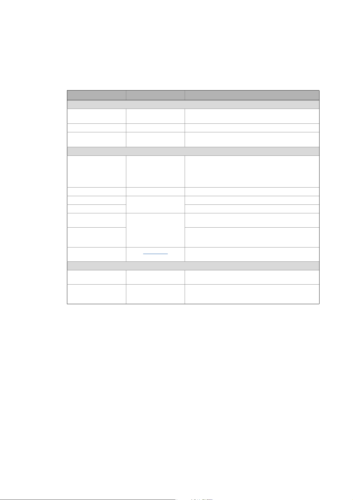
•Line
[5-1] Line topology (S = scanner, A = adapter)
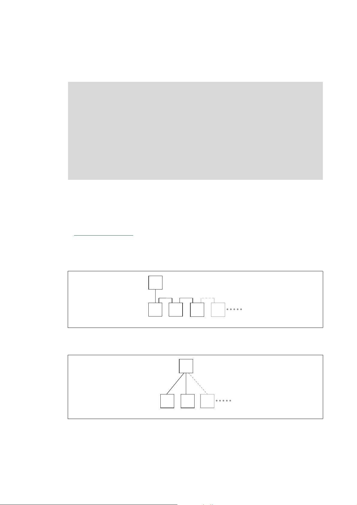
•Switch / star
( 15)
E94AYCEO008
[5-2] Switch / star topology (SW = switch, A = adapter)
16
Lenze · Decentralised frequency inverter 8400 protec (EtherNet/IP™ option) · Communication Manual · DMS 3.0 EN · 07/2014 · TD17
E94AYCEO005
Page 17
5 Installation
S
SWSWSW
SW
SWSW
5.1 Network topology
_ _ _ _ _ _ _ _ _ _ _ _ _ _ _ _ _ _ _ _ _ _ _ _ _ _ _ _ _ _ _ _ _ _ _ _ _ _ _ _ _ _ _ _ _ _ _ _ _ _ _ _ _ _ _ _ _ _ _ _ _ _ _ _
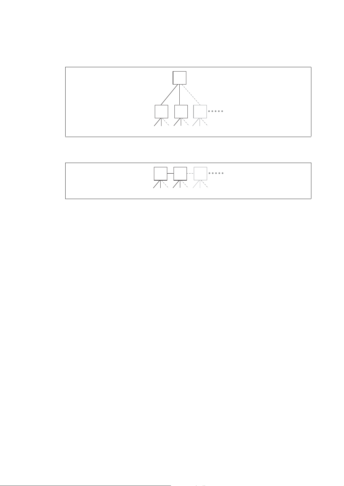
•Tree via switches
E94AYCEO006
[5-3] Tree topology (S = scanner, SW = switch)
•Switch / switch
[5-4] Switch / switch topology (SW = switch)
E94AYCEO007
Lenze · Decentralised frequency inverter 8400 protec (EtherNet/IP™ option) · Communication Manual · DMS 3.0 EN · 07/2014 · TD17 17
Page 18
5 Installation
5.2 EtherNet/IP connection
_ _ _ _ _ _ _ _ _ _ _ _ _ _ _ _ _ _ _ _ _ _ _ _ _ _ _ _ _ _ _ _ _ _ _ _ _ _ _ _ _ _ _ _ _ _ _ _ _ _ _ _ _ _ _ _ _ _ _ _ _ _ _ _
5.2 EtherNet/IP connection
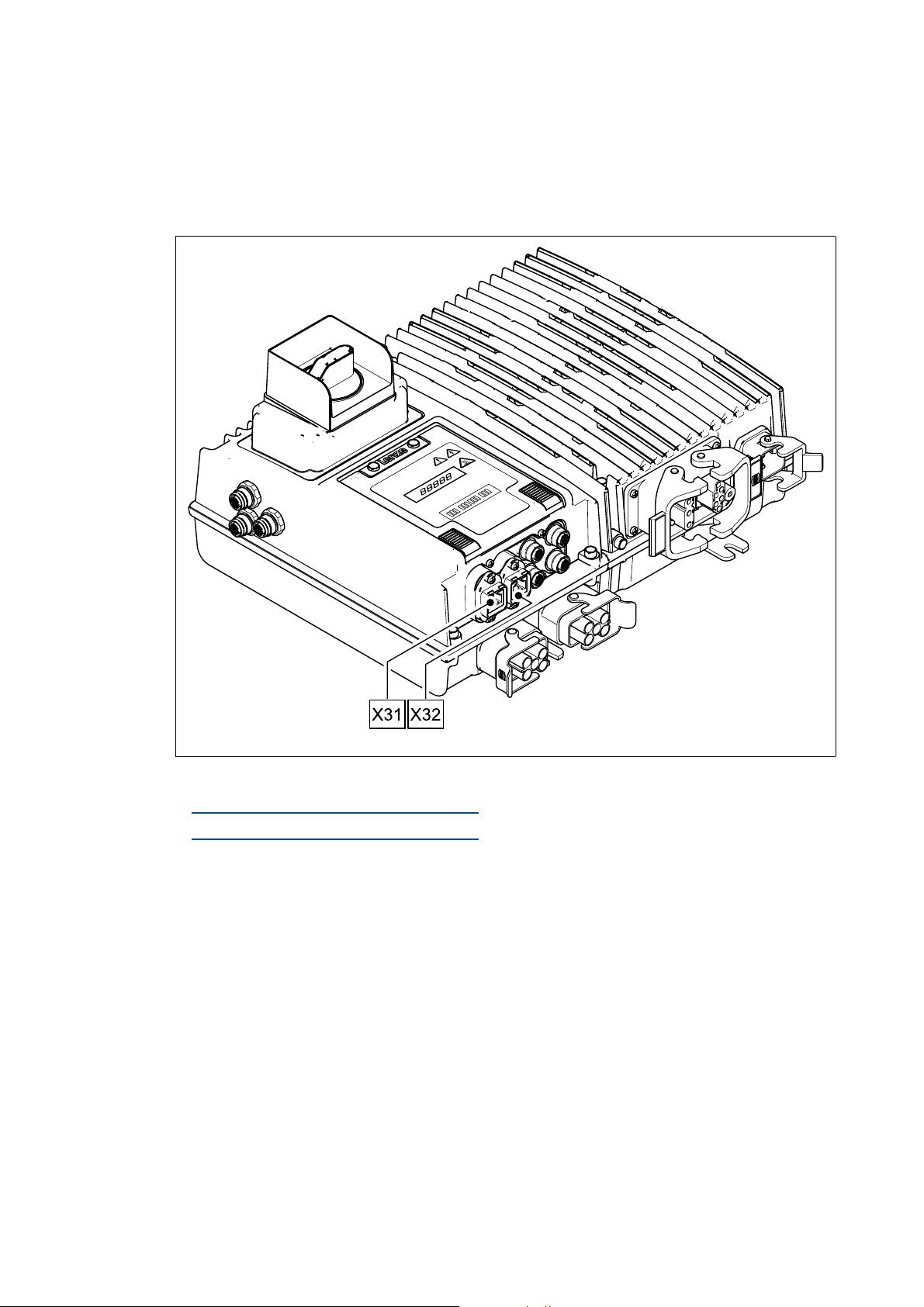
The connection to the EtherNet/IP network is made via the terminals X31 and X32 – depending on
the version via an RJ45 socket or M12 socket (4-pole, D-coded).
E84DWGA010_Kom
[5-5] EtherNet/IP terminals
EtherNet/IP connection via the RJ45 socket ( 19)
EtherNet/IP connection via the M12 socket
( 22)
18
Lenze · Decentralised frequency inverter 8400 protec (EtherNet/IP™ option) · Communication Manual · DMS 3.0 EN · 07/2014 · TD17
Page 19
5 Installation
5.2 EtherNet/IP connection
_ _ _ _ _ _ _ _ _ _ _ _ _ _ _ _ _ _ _ _ _ _ _ _ _ _ _ _ _ _ _ _ _ _ _ _ _ _ _ _ _ _ _ _ _ _ _ _ _ _ _ _ _ _ _ _ _ _ _ _ _ _ _ _
5.2.1 EtherNet/IP connection via the RJ45 socket
A standard Ethernet patch cable is suitable for connecting the Inverter Drive 8400 protec to the
EtherNet/IP fieldbus.
Ethernet cable specification
The installation and removal of the Ethernet cables is optimised for the use of connectors in
accordance with the "Automation Initiative of German Domestic Automobile Manufacturers"
(AIDA).
( 20)
Note!
To prevent the RJ45 socket from being damaged, insert or remove the Ethernet cable
connector straight (at a right angle) into or from the socket.
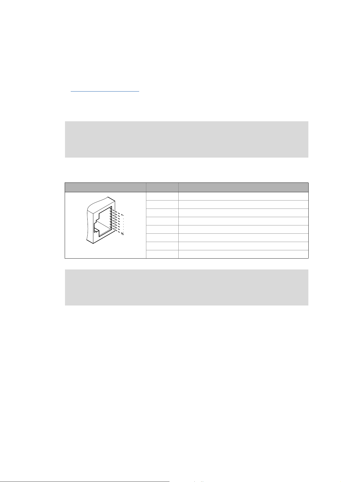
5.2.1.1 Pin assignment
RJ45 socket Pin Signal
1Tx +
2Tx -
3Rx +
4-
5-
6Rx -
E94AYCXX004C
7-
8-
Note!
Dependent on the configuration of the Ethernet port of the device to be connected, we
recommend the use of a cross-over cable.
Tip!
The EtherNet/IP interfaces feature an auto MDIX function. This function adjusts the
polarity of the RJ45 interfaces so that a connection is established irrespective of the polarity
of the opposite EtherNet/IP interface, and irrespective of the cable type used (standard
patch cable or crossover cable).
Lenze · Decentralised frequency inverter 8400 protec (EtherNet/IP™ option) · Communication Manual · DMS 3.0 EN · 07/2014 · TD17 19
Page 20
5 Installation
5.2 EtherNet/IP connection
_ _ _ _ _ _ _ _ _ _ _ _ _ _ _ _ _ _ _ _ _ _ _ _ _ _ _ _ _ _ _ _ _ _ _ _ _ _ _ _ _ _ _ _ _ _ _ _ _ _ _ _ _ _ _ _ _ _ _ _ _ _ _ _
5.2.1.2 Ethernet cable specification
Note!
Only use cables that meet the listed specifications.
Ethernet cable specification
Ethernet standard Standard Ethernet (in accordance with IEEE 802.3), 100Base-TX (Fast
Cable type S/FTP (Screened Foiled Twisted Pair, ISO/IEC 11801 or EN 50173), CAT 5e
Damping 23.2 dB (at 100 MHz and per 100 m)
Crosstalk damping 24 dB (at 100 MHz and per 100 m)
Return loss 10 dB (per 100 m)
Surge impedance 100
Ethernet)
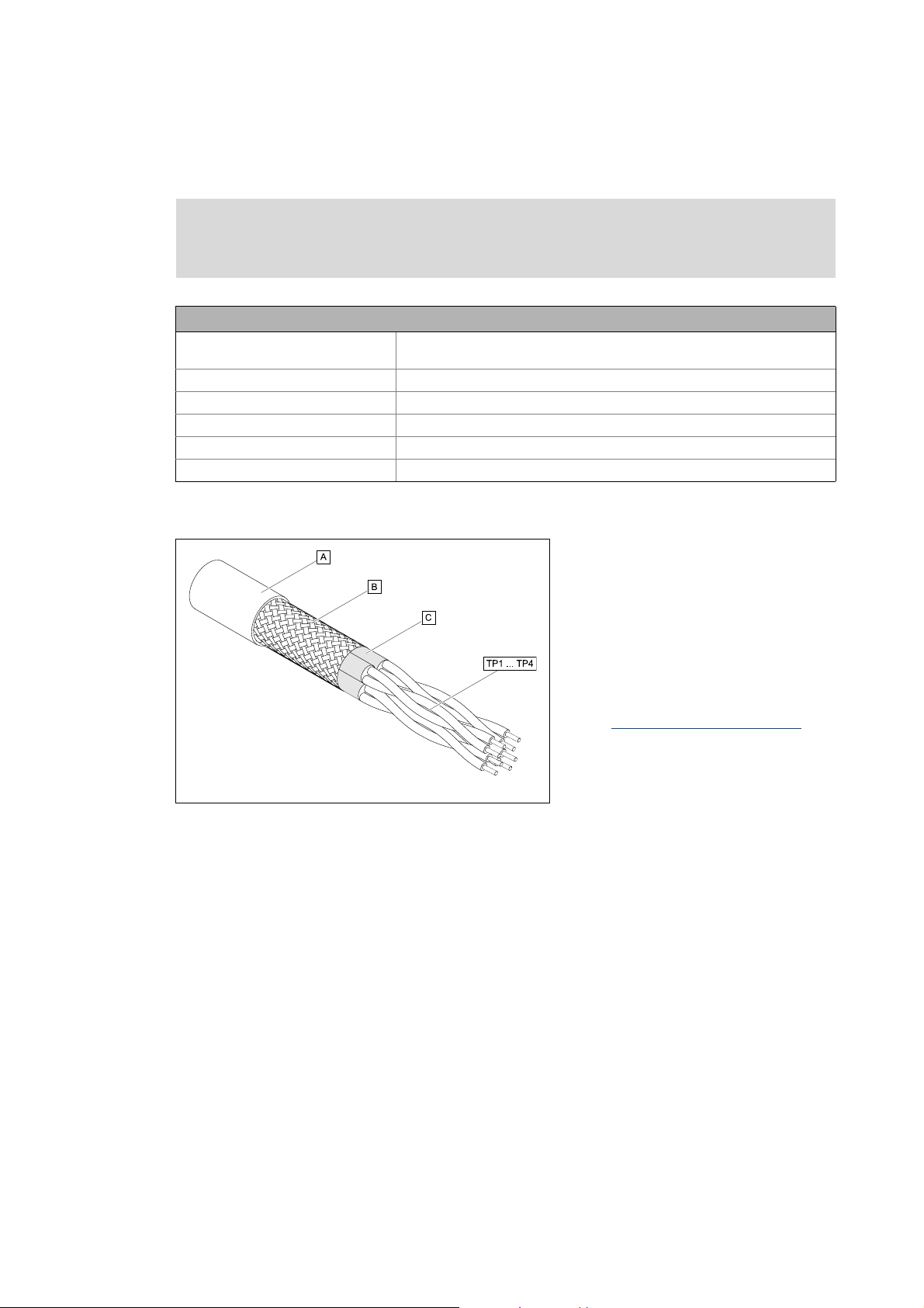
Structure of the Ethernet cable
A Cable insulation
B Braid
E94YCEP016
[5-6] Structure of the Ethernet cable (S/FTP, CAT 5e)
C Foil shield
TP1
Twisted core pairs 1 ... 4
...
Colour code of the Ethernet cable
TP4
( 21)
20
Lenze · Decentralised frequency inverter 8400 protec (EtherNet/IP™ option) · Communication Manual · DMS 3.0 EN · 07/2014 · TD17
Page 21
5 Installation
5.2 EtherNet/IP connection
_ _ _ _ _ _ _ _ _ _ _ _ _ _ _ _ _ _ _ _ _ _ _ _ _ _ _ _ _ _ _ _ _ _ _ _ _ _ _ _ _ _ _ _ _ _ _ _ _ _ _ _ _ _ _ _ _ _ _ _ _ _ _ _
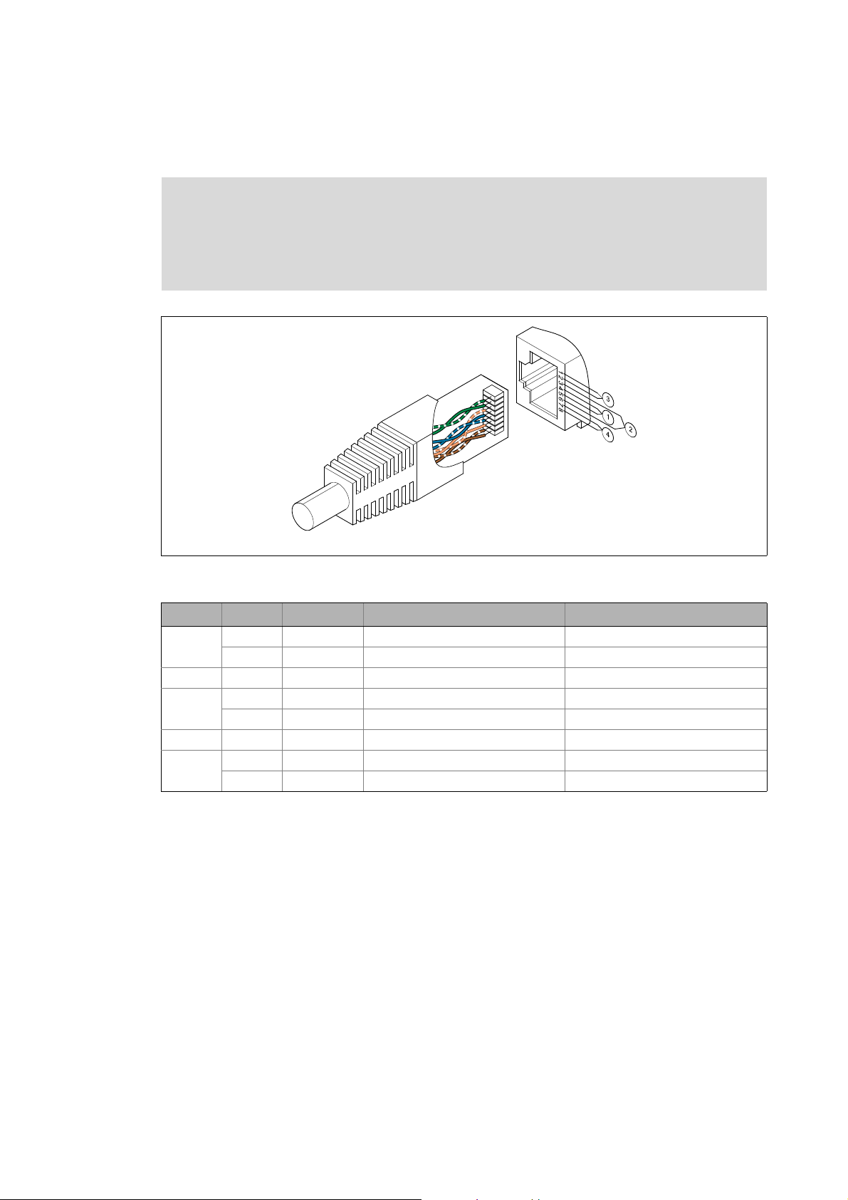
Colour code of the Ethernet cable
Note!
The wiring and colour code are standardised in EIA/TIA 568A/568B.
In accordance with the industrial standard, the use of 4-pin Ethernet cables is
permissible. The cable type only connects the assigned pins 1, 2, 3 and 6 to one another.
[5-7] Ethernet connector in accordance with EIA/TIA 568A/568B
Pair Pin Signal EIA/TIA 568A EIA/TIA 568B
3 1 Tx + White / Green White / Orange
2 Tx - Green Orange
2 3 Rx + White / Orange White / Green
1 4 Blue Blue
5 White / Blue Blue / White
2 6 Rx - Orange Green
4 7 White / Brown White / Brown
8Brown Brown
E94YCEI004A
Lenze · Decentralised frequency inverter 8400 protec (EtherNet/IP™ option) · Communication Manual · DMS 3.0 EN · 07/2014 · TD17 21
Page 22

5 Installation
1
2
3
4
5.2 EtherNet/IP connection
_ _ _ _ _ _ _ _ _ _ _ _ _ _ _ _ _ _ _ _ _ _ _ _ _ _ _ _ _ _ _ _ _ _ _ _ _ _ _ _ _ _ _ _ _ _ _ _ _ _ _ _ _ _ _ _ _ _ _ _ _ _ _ _
5.2.2 EtherNet/IP connection via the M12 socket
Pin assignment
X31 / X32
(M12 socket, 4-pin, D-coded)
Pin Signal
1Tx +
2Rx +
3Tx -
4Rx -
22
Lenze · Decentralised frequency inverter 8400 protec (EtherNet/IP™ option) · Communication Manual · DMS 3.0 EN · 07/2014 · TD17
Page 23

6 Commissioning
6.1 Before initial switch-on
_ _ _ _ _ _ _ _ _ _ _ _ _ _ _ _ _ _ _ _ _ _ _ _ _ _ _ _ _ _ _ _ _ _ _ _ _ _ _ _ _ _ _ _ _ _ _ _ _ _ _ _ _ _ _ _ _ _ _ _ _ _ _ _
6 Commissioning
During commissioning, plant-specific data such as motor parameters, operating parameters,
responses, and parameters for fieldbus communication are defined for the inverter. Lenze devices
use codes for this purpose.
The codes of the inverter and for communication are saved to the memory module in a non-volatile
data set.
In addition, there are codes for diagnosing and monitoring the stations.
Parameter reference
6.1 Before initial switch-on
( 88)
Stop!
Before you switch on the Inverter Drive 8400 protec for the first time, check the entire
wiring for completeness, short circuit, and earth fault.
Lenze · Decentralised frequency inverter 8400 protec (EtherNet/IP™ option) · Communication Manual · DMS 3.0 EN · 07/2014 · TD17 23
Page 24

6 Commissioning
6.2 Configuring the host system (scanner)
_ _ _ _ _ _ _ _ _ _ _ _ _ _ _ _ _ _ _ _ _ _ _ _ _ _ _ _ _ _ _ _ _ _ _ _ _ _ _ _ _ _ _ _ _ _ _ _ _ _ _ _ _ _ _ _ _ _ _ _ _ _ _ _
6.2 Configuring the host system (scanner)
First you have to configure the host (scanner) for communication with the Inverter Drive 8400
protec.
The configuration of EtherNet/IP networks always requires an EtherNet/IP configuration software
(e.g. »RSLogix 5000« from Rockwell) for the host system (scanner).
The configuration software is necessary for the programming of controller programs, EtherNet/IP
configuration, real-time execution and diagnostics.
The basic parameters of the communication module are stored in the internal configuration
memory and can be used by the scanner when the nodes are being detected.
For node detection (fieldbus scan), the corresponding device descriptions of the Lenze device family
are used.
Tip!
Here you will find information on configuring with the »RSLogix 5000« programming
software from Rockwell:
I/O configuration with »RSLogix 5000« version 19 or lower
( 53)
I/O configuration with »RSLogix 5000« version 20 or higher
( 58)
24
Lenze · Decentralised frequency inverter 8400 protec (EtherNet/IP™ option) · Communication Manual · DMS 3.0 EN · 07/2014 · TD17
Page 25
6 Commissioning
6.2 Configuring the host system (scanner)
_ _ _ _ _ _ _ _ _ _ _ _ _ _ _ _ _ _ _ _ _ _ _ _ _ _ _ _ _ _ _ _ _ _ _ _ _ _ _ _ _ _ _ _ _ _ _ _ _ _ _ _ _ _ _ _ _ _ _ _ _ _ _ _
6.2.1 EDS files
Depending on the EtherNet/IP scanner configuration software, the EDS files (Electronic Data Sheet)
may be used for the configuration of the network profile, the communication with the participating
devices and the automatic generation of tags. For this purpose, the EDS files must be imported into
the controller project of the scanner configuration software.
The EDS file required for the configuration can be found in the download area at:
www.Lenze.com
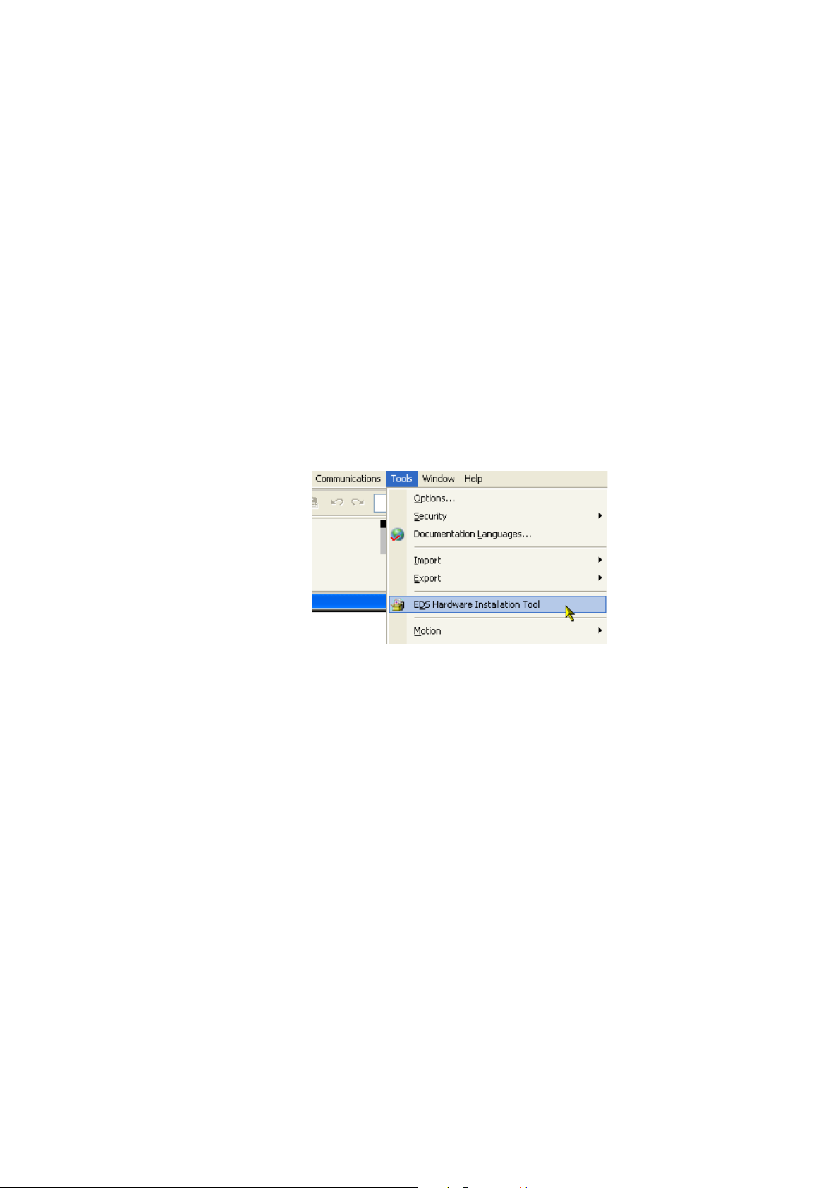
Tip!
From version 20 onwards, Rockwell's »RSLogix 5000« programming software features an
"EDS Hardware Installation Tool" that can be used to ...
• install/import EDS files;
• create EDS files;
• carry out EDS uploads;
• delete EDS files from your controller project.
In »RSLogix 5000«, the dialog for the "EDS Hardware Installation Tool" is self-explanatory
and not described further in this documentation.
Lenze · Decentralised frequency inverter 8400 protec (EtherNet/IP™ option) · Communication Manual · DMS 3.0 EN · 07/2014 · TD17 25
Page 26
6 Commissioning
6.2 Configuring the host system (scanner)
_ _ _ _ _ _ _ _ _ _ _ _ _ _ _ _ _ _ _ _ _ _ _ _ _ _ _ _ _ _ _ _ _ _ _ _ _ _ _ _ _ _ _ _ _ _ _ _ _ _ _ _ _ _ _ _ _ _ _ _ _ _ _ _
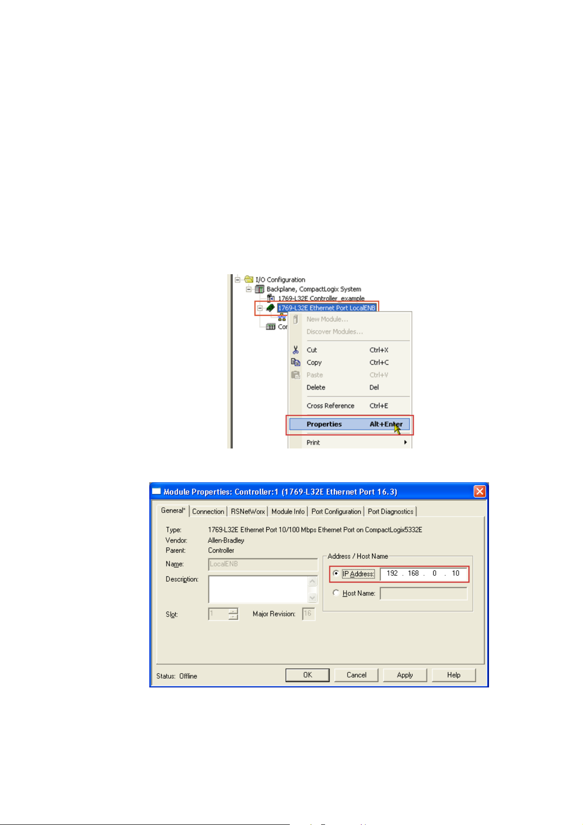
6.2.2 Example: IP configuration of the Allen-Bradley 1769-L32E CompactLogix controller
In this example, the Allen-Bradley CompactLogix control unit 1769-L32E with integrated EtherNet/
IP interface is used for communication with the Inverter Drives 8400 protec.
The »RSLogix 5000« programming software from Rockwell is used for the configuration.
To establish communication via an EtherNet/IP network, add the controller and its scanner to the I/
O configuration.
How to set the IP configuration of the 1769-L32E CompactLogix controller using the
»RSLogix 5000« programming software:
1. Click on the I/O Configuration folder in the configuration tree.
2. Right click on "1769-L32E Ethernet Port LocalENB" and select "Properties" from the context
menu.
3. Go to the General tab of the "Module Properties: ..." dialog window and enter the IP address
of the scanner.
4. Then click OK.
26
Lenze · Decentralised frequency inverter 8400 protec (EtherNet/IP™ option) · Communication Manual · DMS 3.0 EN · 07/2014 · TD17
Page 27
6 Commissioning
6.2 Configuring the host system (scanner)
_ _ _ _ _ _ _ _ _ _ _ _ _ _ _ _ _ _ _ _ _ _ _ _ _ _ _ _ _ _ _ _ _ _ _ _ _ _ _ _ _ _ _ _ _ _ _ _ _ _ _ _ _ _ _ _ _ _ _ _ _ _ _ _
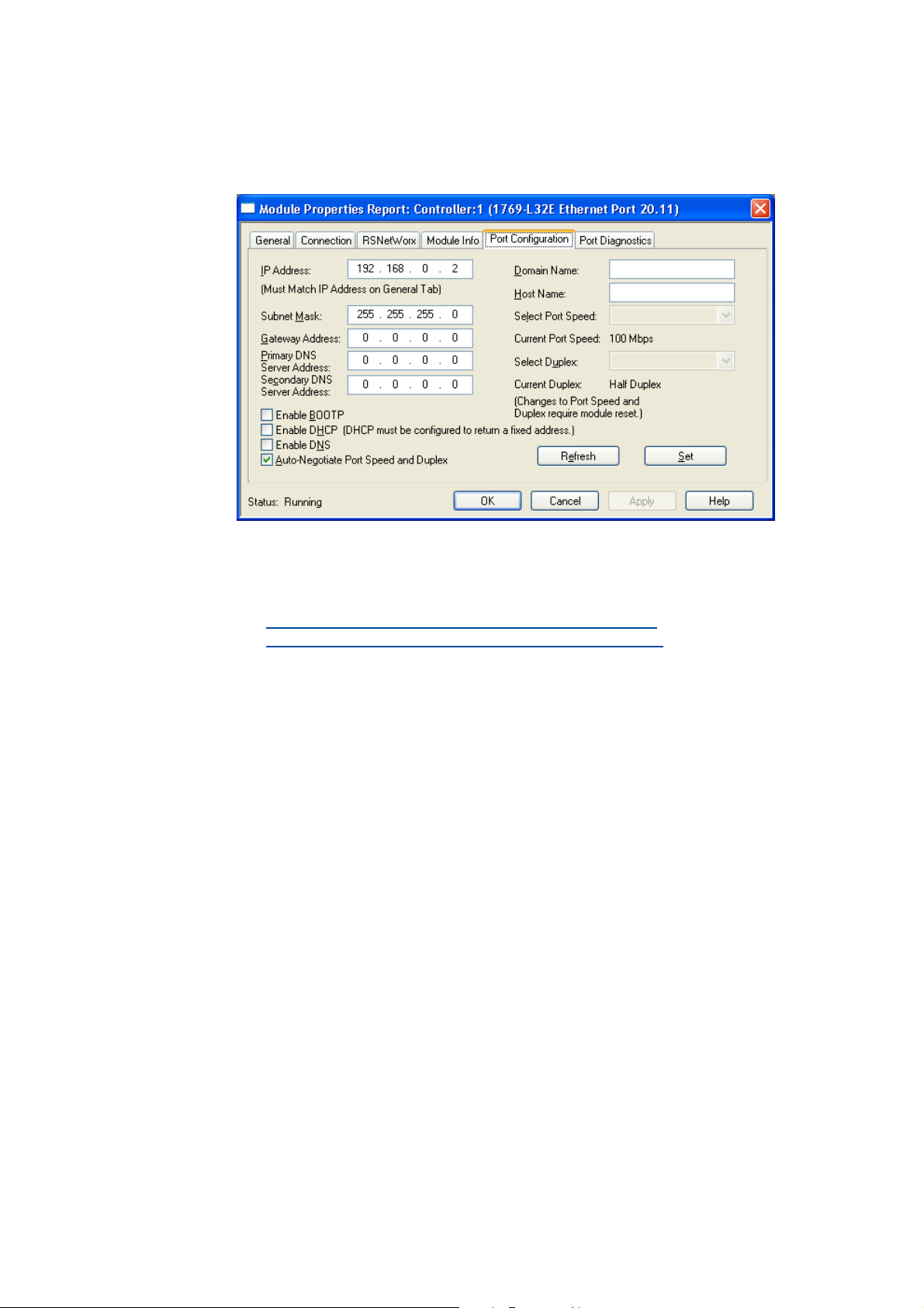
5. Go to the Port Configuration tab and enter the IP configuration, BOOTP setting, Ethernet
baud rate and duplex mode.
6. Then click OK.
• Now, the scanner is configured for the EtherNet/IP network.
• Here you will find information on project planning with the »RSLogix 5000«
programming software from Rockwell:
I/O configuration with »RSLogix 5000« version 19 or lower
I/O configuration with »RSLogix 5000« version 20 or higher
( 53)
( 58)
Lenze · Decentralised frequency inverter 8400 protec (EtherNet/IP™ option) · Communication Manual · DMS 3.0 EN · 07/2014 · TD17 27
Page 28

6 Commissioning
6.3 Setting the IP configuration of the Inverter Drive 8400 protec
_ _ _ _ _ _ _ _ _ _ _ _ _ _ _ _ _ _ _ _ _ _ _ _ _ _ _ _ _ _ _ _ _ _ _ _ _ _ _ _ _ _ _ _ _ _ _ _ _ _ _ _ _ _ _ _ _ _ _ _ _ _ _ _
6.3 Setting the IP configuration of the Inverter Drive 8400 protec
IP configuration is necessary in order to assign an address to the Inverter Drive 8400 protec so that
communication between the PC/»Engineer« or the scanner and the inverter is possible via
EtherNet/IP. For this purpose, an IP address, subnet mask and gateway address have to be assigned.
You can assign these IP parameters for the Inverter Drive 8400 protec in the following ways:
• Setting via the EtherNet/IP configurator of the »Engineer«
• Setting via codes in the »Engineer«
• Setting via a BOOTP/DHCP server
• Setting via the TCP/IP Interface Object (0xF5)
( 31)
( 33)
( 33)
( 29)
Note!
• The assignment of invalid combinations of IP address, subnet mask, and gateway
address can have the consequence that no connection to the EtherNet/IP network can
be established.
•Codes C13010
C13016
• In the case of impermissible settings, the error message EtherNet/IP: Invalid IP
Parameter [0x01bc6533] ( 80) is output.
(IP address), C13011 (subnet mask), C13012 (gateway address), and
(multicast IP address) show the IP parameters currently used.
28
Lenze · Decentralised frequency inverter 8400 protec (EtherNet/IP™ option) · Communication Manual · DMS 3.0 EN · 07/2014 · TD17
Page 29
6 Commissioning
6.3 Setting the IP configuration of the Inverter Drive 8400 protec
_ _ _ _ _ _ _ _ _ _ _ _ _ _ _ _ _ _ _ _ _ _ _ _ _ _ _ _ _ _ _ _ _ _ _ _ _ _ _ _ _ _ _ _ _ _ _ _ _ _ _ _ _ _ _ _ _ _ _ _ _ _ _ _
6.3.1 Setting via the EtherNet/IP configurator of the »Engineer«
Note!
• Changes in the IP parameters will become effective immediately.
• An already existing IP connection to the Inverter Drive 8400 protec is interrupted.
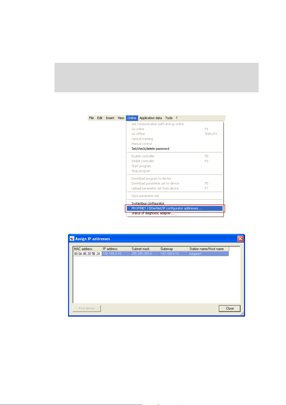
How to set the IP parameters via the EtherNet/IP configurator:
1. Execute the menu command Online PROFINET /EtherNet/IP configurator addresses ....
The "Assign IP addresses" dialog window is opened and all Lenze EtherNet/IP nodes
connected are listed.
Lenze · Decentralised frequency inverter 8400 protec (EtherNet/IP™ option) · Communication Manual · DMS 3.0 EN · 07/2014 · TD17 29
Page 30
6 Commissioning
6.3 Setting the IP configuration of the Inverter Drive 8400 protec
_ _ _ _ _ _ _ _ _ _ _ _ _ _ _ _ _ _ _ _ _ _ _ _ _ _ _ _ _ _ _ _ _ _ _ _ _ _ _ _ _ _ _ _ _ _ _ _ _ _ _ _ _ _ _ _ _ _ _ _ _ _ _ _
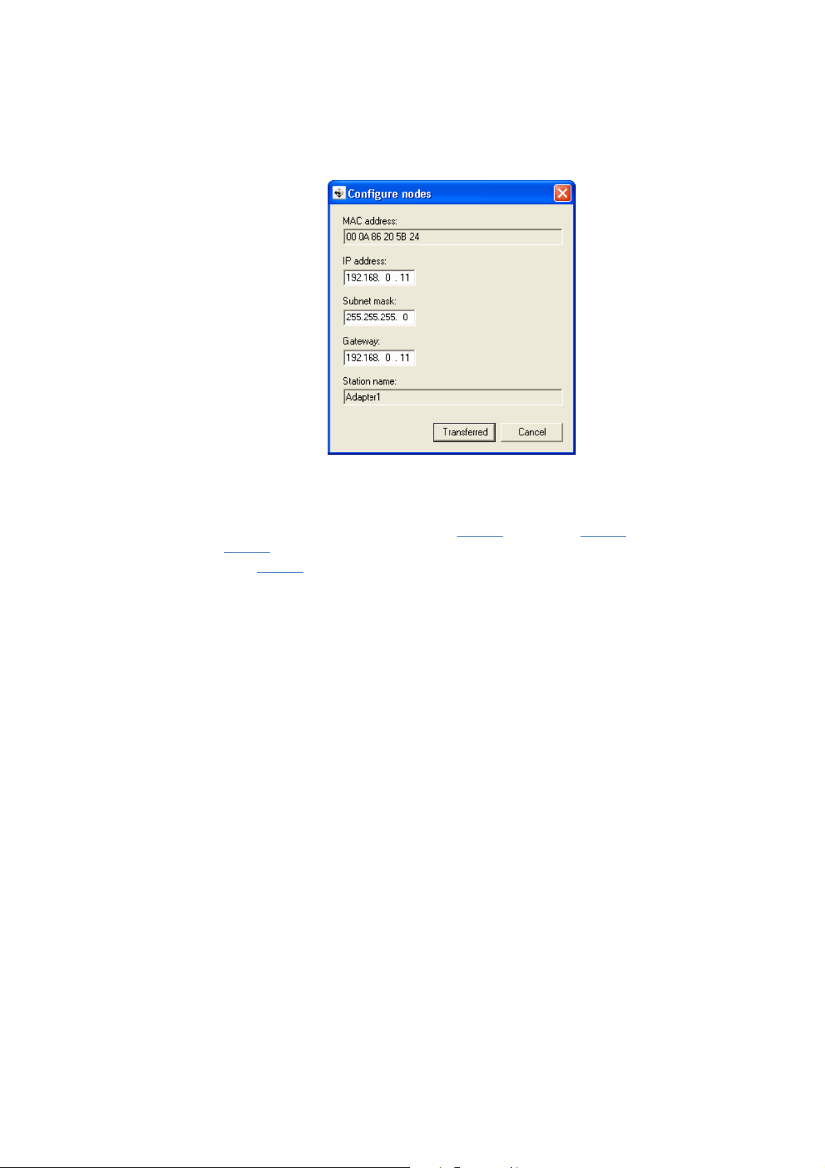
2. A double-click on a EtherNet/IP node opens the "Configure nodes" dialog window.
Here you can set the IP parameters.
3. Click on Transferred.
• The IP configuration is transferred to the corresponding EtherNet/IP node.
• The Inverter Drive 8400 protec carries out a stack reset.
•The IP parameters are written to codes C13000
C13002
•Code C13005
transferred address can be used.
(gateway address).
(IP configuration reference) is set to ’0: Saved address’ to ensure that the
(IP address), C13001 (subnet mask), and
Tip!
Check whether the configuration has been transferred successfully.
For this purpose, open the Assign IP addresses dialog window (see step 1) and click on the
Find device button.
30
Lenze · Decentralised frequency inverter 8400 protec (EtherNet/IP™ option) · Communication Manual · DMS 3.0 EN · 07/2014 · TD17
Page 31

6 Commissioning
6.3 Setting the IP configuration of the Inverter Drive 8400 protec
_ _ _ _ _ _ _ _ _ _ _ _ _ _ _ _ _ _ _ _ _ _ _ _ _ _ _ _ _ _ _ _ _ _ _ _ _ _ _ _ _ _ _ _ _ _ _ _ _ _ _ _ _ _ _ _ _ _ _ _ _ _ _ _
6.3.2 Setting via codes in the »Engineer«
You can also set the IP parameters manually in the »Engineer« under the Settings tab. The values
will be transferred to the corresponding codes.
Settings Description
IP Config Control Selection (C13005
• 0: The IP configuration currently stored in the Inverter Drive 8400 protec
is used.
• 1: The IP configuration is assigned by a BOOTP server using the BOOTP.
• 2: The IP configuration is assigned by a DHCP server using the DHCP.
IP Address Setting of the IP address (C13000
Subnet Mask Setting of the subnet mask (C13001
Gateway Address Setting of the gateway address (C13002
Multicast IP Start Address Setting of the Multicast IP start address (C13006
Setting the multicast configuration
Multicast Config TTL Value Setting of the multicast TTL value (C13019
) of how the IP configuration is to be made:
)
How to activate changed settings in the »Engineer«:
1. Execute device command C00002 = "11: Save all parameter sets".
The current IP configuration is stored in the memory module of the inverter.
2. Carry out a "type 0 reset" to the Identity Object (1 / 0x01)
switch the voltage supply of the Inverter Drive 8400 protec off and then on again.
)
)
)
( 34)
)
( 108) of the bus node or 8400
Lenze · Decentralised frequency inverter 8400 protec (EtherNet/IP™ option) · Communication Manual · DMS 3.0 EN · 07/2014 · TD17 31
Page 32

6 Commissioning
6.3 Setting the IP configuration of the Inverter Drive 8400 protec
_ _ _ _ _ _ _ _ _ _ _ _ _ _ _ _ _ _ _ _ _ _ _ _ _ _ _ _ _ _ _ _ _ _ _ _ _ _ _ _ _ _ _ _ _ _ _ _ _ _ _ _ _ _ _ _ _ _ _ _ _ _ _ _
IP address
The IP address is set/changed in C13000
The IP address currently used is displayed in C13010/1...4
Example: Display of the IP address 192.168.124.16
Code C13010/1
Value 192 168 124 16
.
.
C13010/2 C13010/3 C13010/4
Subnet mask
The subnet mask indicates which part of the IP address is evaluated as net ID or host ID.
Valid subnet masks are defined in accordance with RFC 1878
The subnet mask is set/changed in C13001
The subnet mask currently used is displayed in C13011/1...4
Example: Display of the subnet mask 255.255.255.0
Code C13011/1
Value 255 255 255 0
.
.
C13011/2 C13011/3 C13011/4
Gateway address
The gateway address is valid if the network address of the IP address and the gateway address are
identical.
If the gateway address and the IP address are identical or if the address is ’0.0.0.0’, gateway
functionality is not used.
The gateway address is set/changed in C13002
.
The gateway address currently used is displayed in C13012/1...4
.
Example: Display of the gateway address 192.168.124.16
Code C13012/1
Value 192 168 124 16
C13012/2 C13012/3 C13012/4
32
Lenze · Decentralised frequency inverter 8400 protec (EtherNet/IP™ option) · Communication Manual · DMS 3.0 EN · 07/2014 · TD17
Page 33

6 Commissioning
6.3 Setting the IP configuration of the Inverter Drive 8400 protec
_ _ _ _ _ _ _ _ _ _ _ _ _ _ _ _ _ _ _ _ _ _ _ _ _ _ _ _ _ _ _ _ _ _ _ _ _ _ _ _ _ _ _ _ _ _ _ _ _ _ _ _ _ _ _ _ _ _ _ _ _ _ _ _
6.3.3 Setting via a BOOTP/DHCP server
DHCP is the acronym for "Dynamic Host Configuration Protocol". This protocol is defined in
RFC 2131 and is a compatible advancement of the "Bootstrap Protocol" (BOOTP) according to
RFC 951.
Both protocols enable network nodes to query information about the network configuration (e.g.
the IP address) from a server via a TCP/IP network. The BOOTP/DHCP server assigns the IP address
to the client dynamically from a defined address range. This means that the client receives an
unambiguous IP address.
Code C13005
• Value '0': The IP configuration currently stored in the Inverter Drive 8400 protec is used.
• Value ’1’: BOOTP is used. (Lenze standard setting)
• Value ’2’: DHCP is used.
The setting can also be selected by write access to attribute 3 (configuration control) of instance 1
of the TCP/IP Interface Object (245 / 0xF5)
is used to select how the IP configuration is to be made:
TCP/IP Interface Object (245 / 0xF5).
6.3.4 Setting via the TCP/IP Interface Object (0xF5)
With a scanner, the IP configuration can be set via attribute 5 (interface configuration) of instance 1
of the TCP/IP Interface Object (245 / 0xF5)
After the IP configuration, carry out a node reset ("power off/on" or "Type 0 reset" for the Identity
Object (1 / 0x01) ( 108)).
In the »Engineer«, codes C13010
and C13016
(multicast IP address) show the IP parameters currently used.
(IP address), C13011 (subnet mask), C13012 (gateway address),
TCP/IP Interface Object (245 / 0xF5).
Lenze · Decentralised frequency inverter 8400 protec (EtherNet/IP™ option) · Communication Manual · DMS 3.0 EN · 07/2014 · TD17 33
Page 34

6 Commissioning
6.3 Setting the IP configuration of the Inverter Drive 8400 protec
_ _ _ _ _ _ _ _ _ _ _ _ _ _ _ _ _ _ _ _ _ _ _ _ _ _ _ _ _ _ _ _ _ _ _ _ _ _ _ _ _ _ _ _ _ _ _ _ _ _ _ _ _ _ _ _ _ _ _ _ _ _ _ _
6.3.5 Setting the multicast configuration
Several scanners ("Listen only" or "Input only" connections) can access multicast telegrams which
are sent by the inverter. Settings for multicast configuration have to be carried out as well in the
EtherNet/IP configuration software (e.g. »RSLogix 5000« from Rockwell).
By default, the Inverter Drive 8400 protec automatically generates the Multicast IP start address for
I/O data transfer. The standard TTL value for Multicast transfer is ’1’; the Multicast I/O data
packages are therefore distributed solely via the local network.
Note!
You can also explicitly set the multicast IP start address and the multicast TTL value. We
recommend, however, not to change the default settings in order to ensure a secure
multicast transmission.
The following multicast codes are configurable:
Code Description
C13018
C13019
C13020
Multicast IP Start Address
Multicast IP start addresses serve to send a message to the members of a certain group (i.e. possibly
to several nodes).
The multicast IP start address is set/changed in C13006
The currently used multicast IP address of the inverter is displayed in C13016/1...4
Example: Display of the multicast IP address 239.64.2.224
Code C13016/1
Value 239 64 2 224
Selection for multicast IP addressing via instance attribute 9 (Mcast Config) in the TCP/IP
Interface Object (245 / 0xF5) ( 124)
• Value ’0’: The default algorithm is used.
• Value ’1’: The address from code C13006
Setting of the multicast TTL value for the validity time of data packets in the EtherNet/IP
network
(Instance attribute 8 (TTL Value) in the TCP/IP Interface Object (245 / 0xF5)
Used to set how many multicast IP addresses will be assigned.
(Instance attribute 9 (Num Mcast) in the TCP/IP Interface Object (245 / 0xF5)
C13016/2 C13016/3 C13016/4
is used as multicast IP start address.
( 124))
( 124))
.
.
34
Lenze · Decentralised frequency inverter 8400 protec (EtherNet/IP™ option) · Communication Manual · DMS 3.0 EN · 07/2014 · TD17
Page 35

6 Commissioning
6.4 Establishing an online connection via EtherNet/IP with the Lenze »Engineer«
_ _ _ _ _ _ _ _ _ _ _ _ _ _ _ _ _ _ _ _ _ _ _ _ _ _ _ _ _ _ _ _ _ _ _ _ _ _ _ _ _ _ _ _ _ _ _ _ _ _ _ _ _ _ _ _ _ _ _ _ _ _ _ _
6.4 Establishing an online connection via EtherNet/IP with the Lenze »Engineer«
Note!
• In order to ensure perfect operation of cyclic EtherNet/IP communication, online
access with the »Engineer« should be executed via an IEEE 802.1Q-capable switch.
• The IEEE 8400 802.1Q-capable switch integrated in the Inverter Drive 8400 protec can
manage cyclical EtherNet/IP-communication primarily for normal TCP/IP
communication. In the case of EtherNet/IP, this is done by means of the VLAN
identification in the Ethernet frame (can be set in C13021
• If the redundancy protocol DLR (Device Level Ring) is used, the switch also must be
DLR-compliant.
).
[6-1] Example set-up with an Allen Bradley CompactLogix Controller 1769-L32E (scanner)
For an online connection between the »Engineer« and the inverter, the inverter must have an IP
address (see Setting the IP configuration of the Inverter Drive 8400 protec
( 28)).
Lenze · Decentralised frequency inverter 8400 protec (EtherNet/IP™ option) · Communication Manual · DMS 3.0 EN · 07/2014 · TD17 35
Page 36

6 Commissioning
6.4 Establishing an online connection via EtherNet/IP with the Lenze »Engineer«
_ _ _ _ _ _ _ _ _ _ _ _ _ _ _ _ _ _ _ _ _ _ _ _ _ _ _ _ _ _ _ _ _ _ _ _ _ _ _ _ _ _ _ _ _ _ _ _ _ _ _ _ _ _ _ _ _ _ _ _ _ _ _ _
In the »Engineer«, you can use the Online Set communication path and go online menu
command to select the EtherNet/IP communication path. The previously configured EtherNet/IP
nodes are shown in the "Communication path" dialog window:
If the device access path is not configured correctly, here the IP address of the inverter selected
in the display field can be entered manually.
Via the Search/Enter button, you can establish a connection to devices which have not
appeared in the display field. Corresponding settings for this can be made in the "Enter IP Address"
dialog window that will appear:
Here you can enter an IP address manually or execute the following actions using the buttons:
• Execute the console command Ping.
• Assign the IP address via the Configurator.
Setting via the EtherNet/IP configurator of the »Engineer«
( 29)
36
• Select the device access path to the desired inverter by clicking Find.
After having established the online connection, you can continue work with the »Engineer« as
usual.
Lenze · Decentralised frequency inverter 8400 protec (EtherNet/IP™ option) · Communication Manual · DMS 3.0 EN · 07/2014 · TD17
Page 37

6 Commissioning
6.5 Initial switch-on
_ _ _ _ _ _ _ _ _ _ _ _ _ _ _ _ _ _ _ _ _ _ _ _ _ _ _ _ _ _ _ _ _ _ _ _ _ _ _ _ _ _ _ _ _ _ _ _ _ _ _ _ _ _ _ _ _ _ _ _ _ _ _ _
6.5 Initial switch-on
Mounting instructions for the Inverter Drive 8400 protec
Observe the safety instructions and residual hazards stated.
Note!
Activating changed settings
To activate changed settings ...
• execute device command "11: Save all parameter sets" via inverter code C00002
and ...
• carry out a "type 0 reset" to the Identity Object (1 / 0x01)
switch the voltage supply of the communication module off and then on again.
Protection against uncontrolled restart
After a fault (e.g. short-time mains failure), the restart of a drive is not always wanted
and - in some cases - even not allowed.
( 108) of the bus node or
In the Lenze setting of the Inverter Drives 8400 protec, the restart protection is activated.
The restart behaviour of the inverter can be set via C00142 ("Autostart Option"):
C00142 = 9 (Lenze setting)
• The inverter remains inhibited (even if the fault is no longer active).
• Bit 0 (inhibit at "power-on") and bit 3 (inhibit in the case of undervoltage) are set.
• The drive starts in a controlled mode by an explicit controller enable: LOW-HIGH edge
on a digital input configured correspondingly (terminals X41, X42, X43).
C00142 = 8 (enabled)
• In order to enable the device directly when switching it on, set bit 0 to zero.
• An uncontrolled restart of the drive is possible.
Lenze · Decentralised frequency inverter 8400 protec (EtherNet/IP™ option) · Communication Manual · DMS 3.0 EN · 07/2014 · TD17 37
Page 38

7 Data transfer
_ _ _ _ _ _ _ _ _ _ _ _ _ _ _ _ _ _ _ _ _ _ _ _ _ _ _ _ _ _ _ _ _ _ _ _ _ _ _ _ _ _ _ _ _ _ _ _ _ _ _ _ _ _ _ _ _ _ _ _ _ _ _ _
7 Data transfer
EtherNet/IP uses CIP™ (Common Industrial Protocol) for the data exchange between devices via an
Ethernet network – just like the closely related bus systems DeviceNet and ControlNet.
Lenze implements the CIP following the ODVA standard (Open DeviceNet Vendor Association,
www.odva.org
• Explicit messaging (for parameter data)
• Implicit messaging (for I/O data)
) and supports the two main types of EtherNet/IP communication:
38 Lenze · Decentralised frequency inverter 8400 protec (EtherNet/IP™ option) · Communication Manual · DMS 3.0 EN · 07/2014 · TD17
Page 39

7 Data transfer
7.1 Communication channels
_ _ _ _ _ _ _ _ _ _ _ _ _ _ _ _ _ _ _ _ _ _ _ _ _ _ _ _ _ _ _ _ _ _ _ _ _ _ _ _ _ _ _ _ _ _ _ _ _ _ _ _ _ _ _ _ _ _ _ _ _ _ _ _
7.1 Communication channels
Note!
The terms "input" and "output" refer to the point of view of the scanner:
• Input data is produced by the adapter and consumed by the scanner.
• Output data is produced by the scanner and consumed by the adapter.
EtherNet/IP transmits parameter data and I/O data between the host system (scanner) and the
inverters (adapters) connected to the fieldbus. The data are transmitted via corresponding
communication channels depending on their time-critical behaviour.
The I/O data channel transmits I/O data by means of "implicit messages".
• The inverter is controlled by means of the I/O data.
• The transmission of I/O data is time-critical.
• I/O data are transmitted cyclically between the host system (scanner) and the inverters
(adapters) (permanent exchange of current input and output data).
• The host system (scanner) has direct access to the I/O data (the data are, for example, stored
directly in the I/O area).
• In the case of Inverter Drives 8400 protec, maximally 16 data words (max. 32 bytes) can be
exchanged for each direction.
• I/O data are not stored in the inverter.
• I/O data are e.g. setpoints, actual values, control and status words
The parameter data channel transmits parameter data by means of "explicit messages".
• The transmission of parameter data is usually not time-critical.
• Examples of parameter data are operating parameters, motor data, and diagnostic information.
• The parameter data channel provides access to all Lenze codes.
• Parameter changes must be saved by means of code C00002 of the Inverter Drive 8400 protec.
Lenze · Decentralised frequency inverter 8400 protec (EtherNet/IP™ option) · Communication Manual · DMS 3.0 EN · 07/2014 · TD17 39
Page 40

7 Data transfer
7.2 Telegram types
_ _ _ _ _ _ _ _ _ _ _ _ _ _ _ _ _ _ _ _ _ _ _ _ _ _ _ _ _ _ _ _ _ _ _ _ _ _ _ _ _ _ _ _ _ _ _ _ _ _ _ _ _ _ _ _ _ _ _ _ _ _ _ _
7.2 Telegram types
The "implicit message" and "explicit message" telegram types are transmitted between the host
system (scanner) and the inverter (adapter).
Implicit messages (I/O data transfer)
"Implicit messages" are transmitted or received according to the producer/consumer principle.
There is one transmitter and no receiver or an optional number of receivers.
The "cyclic I/O data" transmission mode is supported. The scanner and the adapter use "cyclic I/O
data" to generate their data independently of each other, which are then transmitted depending on
a timer. The user must set the value of the timer in the scanner.
Explicit messages (parameter data transfer)
"Explicit messages" serve to configure and parameterise the individual EtherNet/IP nodes.
Two nodes have a client/server relationship:
The client transmits a job (request). The server receives this job and tries to accomplish it. The server
then transmits the requested data (positive response) or an error message (negative response).
40
Lenze · Decentralised frequency inverter 8400 protec (EtherNet/IP™ option) · Communication Manual · DMS 3.0 EN · 07/2014 · TD17
Page 41

7 Data transfer
7.3 EtherNet/IP state diagram
_ _ _ _ _ _ _ _ _ _ _ _ _ _ _ _ _ _ _ _ _ _ _ _ _ _ _ _ _ _ _ _ _ _ _ _ _ _ _ _ _ _ _ _ _ _ _ _ _ _ _ _ _ _ _ _ _ _ _ _ _ _ _ _
7.3 EtherNet/IP state diagram
[7-1] EtherNet/IP state diagram
The current EtherNet/IP device state is ...
• output via code C13861
• output in the Identity Object (1 / 0x01)
• displayed via the LEDs BUS-RDY and BUS-ERR (see LED status displays
;
( 108) via instance attributes 5 and 8;
( 74)).
Lenze · Decentralised frequency inverter 8400 protec (EtherNet/IP™ option) · Communication Manual · DMS 3.0 EN · 07/2014 · TD17 41
Page 42

8 I/O data transfer (implicit messages)
_ _ _ _ _ _ _ _ _ _ _ _ _ _ _ _ _ _ _ _ _ _ _ _ _ _ _ _ _ _ _ _ _ _ _ _ _ _ _ _ _ _ _ _ _ _ _ _ _ _ _ _ _ _ _ _ _ _ _ _ _ _ _ _
8 I/O data transfer (implicit messages)
To exchange I/O data (implicit messages) between the host system (scanner) and the inverter
(adapter), you have to ...
• Assign the I/O data to the internal ports (MCI) in the inverter (adapter):
I/O configuration in the »Engineer«
I/O data mapping
• Configure the I/O data transfer in the host (scanner):
I/O configuration with »RSLogix 5000« version 19 or lower
I/O configuration with »RSLogix 5000« version 20 or higher
( 43)
( 48)
( 53)
( 58)
42 Lenze · Decentralised frequency inverter 8400 protec (EtherNet/IP™ option) · Communication Manual · DMS 3.0 EN · 07/2014 · TD17
Page 43

8 I/O data transfer (implicit messages)
8.1 I/O data mapping
_ _ _ _ _ _ _ _ _ _ _ _ _ _ _ _ _ _ _ _ _ _ _ _ _ _ _ _ _ _ _ _ _ _ _ _ _ _ _ _ _ _ _ _ _ _ _ _ _ _ _ _ _ _ _ _ _ _ _ _ _ _ _ _
8.1 I/O data mapping
I/O data transfer takes place via the MCI interface.
• Access to the I/O data takes place via port blocks LP_MciIn and LP_MciOut.
•The LP_MciIn port block maps the received data objects.
•The LP_MciOut port block maps the data objects to be sent.
• Up to 16 data words (32 bytes) per direction can be exchanged.
• The ports/function blocks of the I/O data objects are interconnected with the Lenze »Engineer«.
[8-1] Outer and inner data transfer between bus system, inverter, and application
Reference manual / online help for Inverter Drives 8400 protec
Here you will find detailed information on the port/function block interconnection in
the »Engineer« and on the port blocks.
Lenze · Decentralised frequency inverter 8400 protec (EtherNet/IP™ option) · Communication Manual · DMS 3.0 EN · 07/2014 · TD17 43
Page 44

8 I/O data transfer (implicit messages)
8.2 Technology applications (TA) / drive profiles
_ _ _ _ _ _ _ _ _ _ _ _ _ _ _ _ _ _ _ _ _ _ _ _ _ _ _ _ _ _ _ _ _ _ _ _ _ _ _ _ _ _ _ _ _ _ _ _ _ _ _ _ _ _ _ _ _ _ _ _ _ _ _ _
8.2 Technology applications (TA) / drive profiles
The Inverter Drives 8400 protec is provided with various drive profiles. They define a standardised
or individual control and status word assignment and the standardisation of setpoints and actual
value scalings.
The following drive profiles are supported by the inverter:
• Lenze technology applications / user-definable parameter sets
• "AC Drive Profile" application
8.2.1 Lenze technology applications / user-definable parameter sets
The technology applications integrated in the inverter provide the main signal flow for realising a
general or specific drive solution.
For using the Lenze technology application selection in the »Engineer« via standard device code
C00005, the following assembly object instances have to be used in the host (scanner):
Instance ID Assembly object instance
[dec] [hex]
110 0x6E Custom Output
(from the adapter to the scanner)
111 0x6F Custom Input
(from the adapter to the scanner)
See also Assembly Object (4 / 0x04)
The custom assemblies also allow for a user-definable parameter setting, depending on the
application. Hence, 16 data words (32 bytes) can be freely assigned with variables of the MCI port
blocks in the »Engineer«.
The user-definable parameter setting can be used in addition to the previously set technology
application.
Lenze technology application / configuring user-definable parameter sets
( 111).
( 48)
Tip!
Here you will find information on configuring with the »RSLogix 5000« programming
software from Rockwell:
I/O configuration with »RSLogix 5000« version 19 or lower
I/O configuration with »RSLogix 5000« version 20 or higher
( 53)
( 58)
44
Lenze · Decentralised frequency inverter 8400 protec (EtherNet/IP™ option) · Communication Manual · DMS 3.0 EN · 07/2014 · TD17
Page 45

8 I/O data transfer (implicit messages)
8.2 Technology applications (TA) / drive profiles
_ _ _ _ _ _ _ _ _ _ _ _ _ _ _ _ _ _ _ _ _ _ _ _ _ _ _ _ _ _ _ _ _ _ _ _ _ _ _ _ _ _ _ _ _ _ _ _ _ _ _ _ _ _ _ _ _ _ _ _ _ _ _ _
8.2.2 "AC Drive Profile" application
The "AC Drive Profile" contains ...
• the data basis for motor parameters,
• management functions of the motor control devices,
• Device-specific functions of the inverter, e.g. speed ramps, torque control etc.
For using the "AC Drive Profile", the following assembly object instances in the host (scanner) have
to be used:
Instance ID Assembly object instance
[dec] [hex]
20 0x14 Basic Speed Control Output Outputs: From the scanner to
21 0x15 Extended Speed Control Output
22 0x16 Speed and Torque Control Output
23 0x17 Extended Speed and Torque Control Output
70 0x46 Basic Speed Control Input Inputs: From the adapter to
71 0x47 Extended Speed Control Input
72 0x48 Speed and Torque Control Input
73 0x49 Extended Speed and Torque Control Input
the adapter
the scanner
See also:
• Assembly Object (4 / 0x04)
• "AC Drive Profile" objects ( 131)
( 111)
Reference manual / »Engineer« online help for Inverter Drives 8400 protec
Here you can find detailed information on how to use the "AC Drive Profile".
Tip!
Here you will find information on configuring with the »RSLogix 5000« programming
software from Rockwell:
I/O configuration with »RSLogix 5000« version 19 or lower
I/O configuration with »RSLogix 5000« version 20 or higher
( 53)
( 58)
Lenze · Decentralised frequency inverter 8400 protec (EtherNet/IP™ option) · Communication Manual · DMS 3.0 EN · 07/2014 · TD17 45
Page 46

8 I/O data transfer (implicit messages)
8.3 I/O assemblies
_ _ _ _ _ _ _ _ _ _ _ _ _ _ _ _ _ _ _ _ _ _ _ _ _ _ _ _ _ _ _ _ _ _ _ _ _ _ _ _ _ _ _ _ _ _ _ _ _ _ _ _ _ _ _ _ _ _ _ _ _ _ _ _
8.3 I/O assemblies
Note!
The terms "input" and "output" refer to the point of view of the scanner:
• Assembly input objects (input) are sent from the adapter to the scanner.
• Assembly output objects (output) are sent from the scanner to the adapter.
The length of the I/O data must correspond with the respective resulting length of the
mapped ports (I/O data mapping
The communication module supports the Assembly Object (4 / 0x04) ( 111) and the "AC Drive
Profile" objects ( 131).
For data exchange, the inverter supports the following assembly object instances:
Application Instance ID Assembly object instance
[dec] [hex]
Lenze technology applications /
User-definable parameter sets
"AC Drive Profile" application 20 0x14 Basic Speed Control Output
110 0x6E Custom Output
111 0x6F Custom Input
21 0x15 Extended Speed Control Output
22 0x16 Speed and Torque Control Output
23 0x17 Extended Speed and Torque Control Output
70 0x46 Basic Speed Control Input
71 0x47 Extended Speed Control Input
72 0x48 Speed and Torque Control Input
73 0x49 Extended Speed and Torque Control Input
( 43)).
Assembly output objects (outputs) are usually used for controlling the enable/disable state of the
inverter and for supplying the speed or torque references.
Assembly input objects (inputs) are usually used to monitor the drive status and the runtime values
such as actual speed, current, actual position and position error.
Depending on the data length defined by the scanner, the memory map of the I/O data can have
different sizes.
46
Lenze · Decentralised frequency inverter 8400 protec (EtherNet/IP™ option) · Communication Manual · DMS 3.0 EN · 07/2014 · TD17
Page 47

8 I/O data transfer (implicit messages)
8.3 I/O assemblies
_ _ _ _ _ _ _ _ _ _ _ _ _ _ _ _ _ _ _ _ _ _ _ _ _ _ _ _ _ _ _ _ _ _ _ _ _ _ _ _ _ _ _ _ _ _ _ _ _ _ _ _ _ _ _ _ _ _ _ _ _ _ _ _
Assembly output objects (scanner adapter)
Assembly output objects are assumed to have a 4-byte header (32-bit "run/idle header"). When
mapping the assemblies, this header will automatically be added to the data stream by most AllenBradley PLC/SLC equipment.
If your PLC does not support this header (like the Rockwell PLCs do), add a preceding 32-bit header
to the output image.
You can then define the bit 0 of this header in the process image of your PLC:
•0: Idle mode
• 1: Run mode
For the operation with Rockwell PLCs, adaptations are not required.
Assembly input objects (adapter scanner)
The assembly input objects are mapped in the adapter memory starting with byte 0.
The input objects are transmitted in a "modeless" manner, i.e. a 4-byte header (32-bit "Run/Idle
header") is not included in the transfer.
So the start address in the assembly memory map is the actual start of the first assembly data
element.
Please observe the actual assembly lengths when mapping the input objects to the controller
memory.
The contents of the input data depends on the I/O data arrangement in the inverter (I/O data
mapping ( 43)).
Lenze · Decentralised frequency inverter 8400 protec (EtherNet/IP™ option) · Communication Manual · DMS 3.0 EN · 07/2014 · TD17 47
Page 48

8 I/O data transfer (implicit messages)
8.4 I/O configuration in the »Engineer«
_ _ _ _ _ _ _ _ _ _ _ _ _ _ _ _ _ _ _ _ _ _ _ _ _ _ _ _ _ _ _ _ _ _ _ _ _ _ _ _ _ _ _ _ _ _ _ _ _ _ _ _ _ _ _ _ _ _ _ _ _ _ _ _
8.4 I/O configuration in the »Engineer«
Lenze technology application / configuring user-definable parameter sets
How to configure the Lenze technology applications / user-definable parameter sets in the
»Engineer«:
1. Select or change the application (C00005) in the Application parameter tab.
In the example, the "speed actuating drive" application (C00005 = 1000) is configured.
• Click the application button:
• Select the application in the "Insert application" dialog box.
2. Make the default setting of the I/O configuration.
Select "MCI" control mode (C00007 = 40).
switch-off positioning
speed actuating drive
table positioning
48
Lenze · Decentralised frequency inverter 8400 protec (EtherNet/IP™ option) · Communication Manual · DMS 3.0 EN · 07/2014 · TD17
Page 49

8 I/O data transfer (implicit messages)
8.4 I/O configuration in the »Engineer«
_ _ _ _ _ _ _ _ _ _ _ _ _ _ _ _ _ _ _ _ _ _ _ _ _ _ _ _ _ _ _ _ _ _ _ _ _ _ _ _ _ _ _ _ _ _ _ _ _ _ _ _ _ _ _ _ _ _ _ _ _ _ _ _
3. On the Ports tab, the port blocks
shown.
MCI_IN and MCI_OUT for the I/O data objects are
• By clicking the required port, the preconfigured signal combination can be obtained
from the
• If you want to complement or change the signal combination, click the
Variable … button.
Application variables.
Change
Lenze · Decentralised frequency inverter 8400 protec (EtherNet/IP™ option) · Communication Manual · DMS 3.0 EN · 07/2014 · TD17 49
Page 50

8 I/O data transfer (implicit messages)
8.4 I/O configuration in the »Engineer«
_ _ _ _ _ _ _ _ _ _ _ _ _ _ _ _ _ _ _ _ _ _ _ _ _ _ _ _ _ _ _ _ _ _ _ _ _ _ _ _ _ _ _ _ _ _ _ _ _ _ _ _ _ _ _ _ _ _ _ _ _ _ _ _
4. In the "Edit port" dialog window, you can assign signals to the I/O data words via the
button.
Select the signals and confirm the selection with OK.
50
Lenze · Decentralised frequency inverter 8400 protec (EtherNet/IP™ option) · Communication Manual · DMS 3.0 EN · 07/2014 · TD17
Page 51

8 I/O data transfer (implicit messages)
8.4 I/O configuration in the »Engineer«
_ _ _ _ _ _ _ _ _ _ _ _ _ _ _ _ _ _ _ _ _ _ _ _ _ _ _ _ _ _ _ _ _ _ _ _ _ _ _ _ _ _ _ _ _ _ _ _ _ _ _ _ _ _ _ _ _ _ _ _ _ _ _ _
For some data words, you can also assign signals to the individual bits via the and
buttons.
W Select the signals and then confirm the selection with OK.
5. Use the standard device code C00002 to execute the command "11: Save all parameter
sets".
The changed settings are activated and saved with mains failure protection.
Lenze · Decentralised frequency inverter 8400 protec (EtherNet/IP™ option) · Communication Manual · DMS 3.0 EN · 07/2014 · TD17 51
Page 52

8 I/O data transfer (implicit messages)
8.4 I/O configuration in the »Engineer«
_ _ _ _ _ _ _ _ _ _ _ _ _ _ _ _ _ _ _ _ _ _ _ _ _ _ _ _ _ _ _ _ _ _ _ _ _ _ _ _ _ _ _ _ _ _ _ _ _ _ _ _ _ _ _ _ _ _ _ _ _ _ _ _
Preconfigured signal combination in the "FB Editor"
The preconfigured signal combination is activated by setting code C00007 = "40: MCI" in the
standard device.
The function block editor (FB Editor) can be used to display the port blocks LP_MciIn and LP_MciOut
with the preconfigured signal combinations:
Here, signal combinations can be added or changed.
Reference manual / online help for Inverter Drives 8400 protec
Here you will find detailed information on the port/function block interconnection in
the »Engineer« and on the port blocks.
52
Lenze · Decentralised frequency inverter 8400 protec (EtherNet/IP™ option) · Communication Manual · DMS 3.0 EN · 07/2014 · TD17
Page 53

8 I/O data transfer (implicit messages)
8.5 I/O configuration with »RSLogix 5000« version 19 or lower
_ _ _ _ _ _ _ _ _ _ _ _ _ _ _ _ _ _ _ _ _ _ _ _ _ _ _ _ _ _ _ _ _ _ _ _ _ _ _ _ _ _ _ _ _ _ _ _ _ _ _ _ _ _ _ _ _ _ _ _ _ _ _ _
8.5 I/O configuration with »RSLogix 5000« version 19 or lower
The following example describes the I/O configuration of the Allen-Bradley 1769-L32E
CompactLogix controller using the Rockwell »RSLogix 5000« programming software up to version
19.
Up to and including software version 19 the I/O configuration is carried out without
EDS files ( 25).
How to carry out the I/O configuration, taking the CompactLogix controller 1769-L32E
with »RSLogix 5000« as an example:
1. Click the I/O Configuration folder in the configuration tree.
For the 1769-L32E CompactLogix controller, the I/O configuration already includes a local
Ethernet port.
If a SoftLogic or ControlLogix controller is used, an Ethernet port scanner needs to be added
to the configuration.
Lenze · Decentralised frequency inverter 8400 protec (EtherNet/IP™ option) · Communication Manual · DMS 3.0 EN · 07/2014 · TD17 53
Page 54

8 I/O data transfer (implicit messages)
8.5 I/O configuration with »RSLogix 5000« version 19 or lower
_ _ _ _ _ _ _ _ _ _ _ _ _ _ _ _ _ _ _ _ _ _ _ _ _ _ _ _ _ _ _ _ _ _ _ _ _ _ _ _ _ _ _ _ _ _ _ _ _ _ _ _ _ _ _ _ _ _ _ _ _ _ _ _
2. Right click on "Ethernet" and execute the "New Module ..." command from the context
menu.
3. Open "Communications" and select "ETHERNET-MODULE | Generic Ethernet Module".
4. Confirm the selection with OK.
54
Lenze · Decentralised frequency inverter 8400 protec (EtherNet/IP™ option) · Communication Manual · DMS 3.0 EN · 07/2014 · TD17
Page 55

8 I/O data transfer (implicit messages)
8.5 I/O configuration with »RSLogix 5000« version 19 or lower
_ _ _ _ _ _ _ _ _ _ _ _ _ _ _ _ _ _ _ _ _ _ _ _ _ _ _ _ _ _ _ _ _ _ _ _ _ _ _ _ _ _ _ _ _ _ _ _ _ _ _ _ _ _ _ _ _ _ _ _ _ _ _ _
5. Go to the "New Module" dialog window and define the properties of the newly added
device .
The terms "input" and "output" refer to the point of view of the scanner:
• Assembly input objects (input) are sent from the adapter to the scanner.
• Assembly output objects (output) are sent from the scanner to the adapter.
Settings for Lenze technology applications or user-definable parameter sets:
If a Lenze technology application or an individual parameter set is used in the inverter, the
assembly object instances "Input = 111" and "Output = 110" can be used to
exchange up to 16 user-definable words (INT) via ports MCI_IN and MCI_OUT.
Go to "Configuration" and enter the Assembly instance "130" and the Size "0".
Lenze · Decentralised frequency inverter 8400 protec (EtherNet/IP™ option) · Communication Manual · DMS 3.0 EN · 07/2014 · TD17 55
Page 56

8 I/O data transfer (implicit messages)
8.5 I/O configuration with »RSLogix 5000« version 19 or lower
_ _ _ _ _ _ _ _ _ _ _ _ _ _ _ _ _ _ _ _ _ _ _ _ _ _ _ _ _ _ _ _ _ _ _ _ _ _ _ _ _ _ _ _ _ _ _ _ _ _ _ _ _ _ _ _ _ _ _ _ _ _ _ _
Settings for an "AC Drive Profile" application:
The assembly object instances "Input = 73" and "Output = 23" shown here
exemplify the use of the AC Drive Profile "Extended Speed and Torque".
Settings Description
Name Device name or type of inverter, usually with reference to the process (in the
Comm Format Data format for the assembly object instances ("connection parameters" area)
IP Address IP address of the inverter
Input Assembly object instance for input objects
Output Assembly object instance for output objects
Configuration Select the Assembly instance "130" and the Size "0" for the configuration. These
example "My_E84AYCEO")
• T he IP address must be in the same subnetwork like the controller. (Depending on
the subnet mask; in general, the first 3 octets of the IP address must be identical.)
• DNS is not supported; the host name merely describes the device.
• Max. 16 input data words (32 bytes, 16 bits/word)
• The number of input data must correspond to the length of the mapped ports in
the transmit PDO (PDO_TX0), otherwise the adapter will reject the connection
with the error message "Invalid Target to Originator Size" (0x0128).
I/O data mapping
• Max. 16 output data words (32 bytes, 16 bits/word)
• The number of output data must correspond to the length of the mapped ports
in the receive PDO (PDO_RX0), otherwise the adapter will reject the connection
with the error message "Invalid Originator to Target Size" (0x0127).
I/O data mapping
values are required!
( 43)
( 43)
56
6. Complete the settings with OK.
Lenze · Decentralised frequency inverter 8400 protec (EtherNet/IP™ option) · Communication Manual · DMS 3.0 EN · 07/2014 · TD17
Page 57

8 I/O data transfer (implicit messages)
8.5 I/O configuration with »RSLogix 5000« version 19 or lower
_ _ _ _ _ _ _ _ _ _ _ _ _ _ _ _ _ _ _ _ _ _ _ _ _ _ _ _ _ _ _ _ _ _ _ _ _ _ _ _ _ _ _ _ _ _ _ _ _ _ _ _ _ _ _ _ _ _ _ _ _ _ _ _
7. Under I/O Configuration in the configuration tree, right click "1769-L32E Ethernet Port
LocalENB" and select "Properties".
8. Go to the Connection tab and set further properties.
Required setting
Setting Description
Requested Packet
Interval (RPI)
Set RPI 4.0 ms. (Standard setting: 10 ms)
The RPI [ms] specifies the intervals for the I/O data exchange between the inverter
(adapter) and the controller (scanner).
Optional settings
Settings Description
Inhibit module This option serves to interrupt or inhibit the communication to the adapter.
Major Fault On
Controller If Connection
Fails While In Run Mode
Use Unicast Connection
over EtherNet/IP
This option serves to put the drive into the error status if the EtherNet/IP connection
to the inverter fails while the controller is running.
Option deactivated (standard setting):
• The input data is sent from the adapter to the scanner by means of multicast
telegrams.
• Other scanners can access this data in addition to the currently configured
scanner ("Listen only" or "Input only" connections).
Option activated:
The input data is sent from the adapter to the scanner by means of unicast
telegrams.
9. Complete the settings with OK.
• The I/O configuration is now complete.
• The corresponding tags will then be created in the "Controller Tags" of the controller
project.
10. The last step is Saving the I/O configuration in »RSLogix 5000«
( 68).
Lenze · Decentralised frequency inverter 8400 protec (EtherNet/IP™ option) · Communication Manual · DMS 3.0 EN · 07/2014 · TD17 57
Page 58

8 I/O data transfer (implicit messages)
8.6 I/O configuration with »RSLogix 5000« version 20 or higher
_ _ _ _ _ _ _ _ _ _ _ _ _ _ _ _ _ _ _ _ _ _ _ _ _ _ _ _ _ _ _ _ _ _ _ _ _ _ _ _ _ _ _ _ _ _ _ _ _ _ _ _ _ _ _ _ _ _ _ _ _ _ _ _
8.6 I/O configuration with »RSLogix 5000« version 20 or higher
The following example describes the I/O configuration of the Allen-Bradley 1769-L32E
CompactLogix controller using the Rockwell »RSLogix 5000« programming software from version
20.
From software version 20 onwards, EDS files
( 25) are used for the I/O configuration.
How to carry out the I/O configuration, taking the CompactLogix controller 1769-L32E
with »RSLogix 5000« as an example:
1. Use the "EDS Hardware Installation Tool" item to import the EDS files
EtherNet/IP nodes.
In »RSLogix 5000«, the dialog for the "EDS Hardware Installation Tool" is self-explanatory
and not described further in this documentation.
2. Click the I/O Configuration folder in the configuration tree.
( 25) of the
58
For the 1769-L32E CompactLogix controller, the I/O configuration already includes a local
Ethernet port.
If a SoftLogic or ControlLogix controller is used, an Ethernet port scanner needs to be added
to the configuration.
Lenze · Decentralised frequency inverter 8400 protec (EtherNet/IP™ option) · Communication Manual · DMS 3.0 EN · 07/2014 · TD17
Page 59

8 I/O data transfer (implicit messages)
8.6 I/O configuration with »RSLogix 5000« version 20 or higher
_ _ _ _ _ _ _ _ _ _ _ _ _ _ _ _ _ _ _ _ _ _ _ _ _ _ _ _ _ _ _ _ _ _ _ _ _ _ _ _ _ _ _ _ _ _ _ _ _ _ _ _ _ _ _ _ _ _ _ _ _ _ _ _
3. Right click on "Ethernet" and execute the "New Module ..." command from the context
menu.
4. In the "Select Module Type" dialog box, open the Catalog tab and select "E84DGYCG
protec".
5. Confirm the selection with Create.
Lenze · Decentralised frequency inverter 8400 protec (EtherNet/IP™ option) · Communication Manual · DMS 3.0 EN · 07/2014 · TD17 59
Page 60

8 I/O data transfer (implicit messages)
8.6 I/O configuration with »RSLogix 5000« version 20 or higher
_ _ _ _ _ _ _ _ _ _ _ _ _ _ _ _ _ _ _ _ _ _ _ _ _ _ _ _ _ _ _ _ _ _ _ _ _ _ _ _ _ _ _ _ _ _ _ _ _ _ _ _ _ _ _ _ _ _ _ _ _ _ _ _
6. In the "New Module" dialog window, select the General tab and allocate a name and
an unique IP address.
Example settings:
DNS is not supported; the host name merely describes the device.
7. Click the Change ... button.
60
Lenze · Decentralised frequency inverter 8400 protec (EtherNet/IP™ option) · Communication Manual · DMS 3.0 EN · 07/2014 · TD17
Page 61

8 I/O data transfer (implicit messages)
8.6 I/O configuration with »RSLogix 5000« version 20 or higher
_ _ _ _ _ _ _ _ _ _ _ _ _ _ _ _ _ _ _ _ _ _ _ _ _ _ _ _ _ _ _ _ _ _ _ _ _ _ _ _ _ _ _ _ _ _ _ _ _ _ _ _ _ _ _ _ _ _ _ _ _ _ _ _
8. Go to the "Module Definition" dialog window and make the connection settings.
The terms "input" and "output" refer to the point of view of the scanner:
• Assembly input objects (input) are sent from the adapter to the scanner.
• Assembly output objects (output) are sent from the scanner to the adapter.
Settings for Lenze technology applications or user-definable parameter sets:
• Select "Exclusive Owner - Custom" connection.
If you use the Lenze technology applications or user-definable parameter sets in the
inverter, the "Exclusive Owner - Custom" assembly object instance always has to be
selected.
•SetData type = INT.
The INT data type is exchanged via the ports MCI_IN and MCI_OUT of the Inverter Drives
8400 protec. In case of the SINT data type, an additional PLC logic is required for
conversion.
•SetTag Suffix = 1.
A tag suffix formulates a module-describing tag name.
Lenze · Decentralised frequency inverter 8400 protec (EtherNet/IP™ option) · Communication Manual · DMS 3.0 EN · 07/2014 · TD17 61
Page 62

8 I/O data transfer (implicit messages)
8.6 I/O configuration with »RSLogix 5000« version 20 or higher
_ _ _ _ _ _ _ _ _ _ _ _ _ _ _ _ _ _ _ _ _ _ _ _ _ _ _ _ _ _ _ _ _ _ _ _ _ _ _ _ _ _ _ _ _ _ _ _ _ _ _ _ _ _ _ _ _ _ _ _ _ _ _ _
Settings for an "AC Drive Profile" application:
• Select "AC Drive" connection.
In the example, the AC Drive Profile "Exclusive Owner - AC Drive Ext. Speed & Torque" is
used.
•SetData type = INT.
The INT data type is exchanged via the ports MCI_IN and MCI_OUT of the Inverter Drives
8400 protec. In case of the SINT data type, an additional PLC logic is required for
conversion.
•SetTag Suffix = 1.
A tag suffix formulates a module-describing tag name.
9. Complete the settings with OK.
62
Lenze · Decentralised frequency inverter 8400 protec (EtherNet/IP™ option) · Communication Manual · DMS 3.0 EN · 07/2014 · TD17
Page 63

8 I/O data transfer (implicit messages)
8.6 I/O configuration with »RSLogix 5000« version 20 or higher
_ _ _ _ _ _ _ _ _ _ _ _ _ _ _ _ _ _ _ _ _ _ _ _ _ _ _ _ _ _ _ _ _ _ _ _ _ _ _ _ _ _ _ _ _ _ _ _ _ _ _ _ _ _ _ _ _ _ _ _ _ _ _ _
10. Open the "New Module" dialog window, select the Connection tab and set further
properties.
"Name" displays the name of the connection set under 8..
The example shows an "Exclusive Owner - Custom" connection. According to this, the name of an
"AC Drive Profile" connection may be displayed here too.
Required settings
Settings Description
Requested Packet
Interval (RPI)
Input type Select the "Multicast" input type.
Set RPI 4.0 ms. (Standard: 10 ms)
The RPI [ms] specifies the intervals for the I/O data exchange between the inverter
(adapter) and the controller (scanner).
• The input data is sent from the adapter to the scanner by means of multicast
telegrams.
• Other scanners can access this data in addition to the currently configured
scanner ("Listen only" or "Input only" connections).
Optional settings
Settings Description
Inhibit module This option serves to interrupt or inhibit the communication to the adapter.
Major Fault On
Controller If Connection
Fails While In Run Mode
This option serves to put the drive into the error status if the EtherNet/IP connection
to the inverter fails while the controller is running.
Lenze · Decentralised frequency inverter 8400 protec (EtherNet/IP™ option) · Communication Manual · DMS 3.0 EN · 07/2014 · TD17 63
Page 64

8 I/O data transfer (implicit messages)
8.6 I/O configuration with »RSLogix 5000« version 20 or higher
_ _ _ _ _ _ _ _ _ _ _ _ _ _ _ _ _ _ _ _ _ _ _ _ _ _ _ _ _ _ _ _ _ _ _ _ _ _ _ _ _ _ _ _ _ _ _ _ _ _ _ _ _ _ _ _ _ _ _ _ _ _ _ _
11. Complete the settings with OK.
• The inverter is inserted in the configuration tree under the "I/O Configuration".
• The corresponding tags are created in the "Controller Tags".
• The example shows the ...
input assembly tags as "MY_EIP8400_FROM_EDS:I1";
output assembly tags as "MY_EIP8400_FROM_EDS:O1";
If you click the "+" in front of the assembly tag name, all data contained in the assembly
tags are shown below it. You can create "alias tags" to reference to single bits of the
assembly tag.
64
Lenze · Decentralised frequency inverter 8400 protec (EtherNet/IP™ option) · Communication Manual · DMS 3.0 EN · 07/2014 · TD17
Page 65

8 I/O data transfer (implicit messages)
8.6 I/O configuration with »RSLogix 5000« version 20 or higher
_ _ _ _ _ _ _ _ _ _ _ _ _ _ _ _ _ _ _ _ _ _ _ _ _ _ _ _ _ _ _ _ _ _ _ _ _ _ _ _ _ _ _ _ _ _ _ _ _ _ _ _ _ _ _ _ _ _ _ _ _ _ _ _
12. Create an "alias tag".
Example with the assembly object instance 23 (0x17):
For a forward motion of a conveyor, bit ’0’ (Run Fwd) is to be referenced by byte ’0’.
Instance Byte Bit 7 Bit 6 Bit 5 Bit 4 Bit 3 Bit 2 Bit 1 Bit 0
23
(0x17)
0
1
2
3
4
5
Net
Ref
NetCtrl Fault
Reset
Speed Reference (Low Byte)
Speed Reference (High Byte)
Torque Reference (Low Byte)
Torque Reference (High Byte)
Run
Rev
Run
Fwd
Note!
• NetCtrl (Bit 5) and NetRef (Bit 6) have to be set in order that the inverter can receive
start/stop commands and speed/torque command via the network.
• In order to be able to use the torque control of the assembly object distance 23 (0x17),
the "DriveMode" attribute has to be written by means of explicit message
transmission.
Write "DriveMode" attribute
( 137)
Right-click an assembly tag and select the command "New Tag..." in the context menu.
Lenze · Decentralised frequency inverter 8400 protec (EtherNet/IP™ option) · Communication Manual · DMS 3.0 EN · 07/2014 · TD17 65
Page 66

8 I/O data transfer (implicit messages)
8.6 I/O configuration with »RSLogix 5000« version 20 or higher
_ _ _ _ _ _ _ _ _ _ _ _ _ _ _ _ _ _ _ _ _ _ _ _ _ _ _ _ _ _ _ _ _ _ _ _ _ _ _ _ _ _ _ _ _ _ _ _ _ _ _ _ _ _ _ _ _ _ _ _ _ _ _ _
13. Go to the "New Tag" dialog window and ...
•assign a Name for the tag (in the example: "Conveyor_1_RUN_FWD");
•set Type = "Alias";
• select the Alias address which is to be referenced for the alias tag.
(in the example: "MY_EIP8400_FROM_EDS:O1.Data(0).0" (bit ’0’ of byte ’0’)
66
Lenze · Decentralised frequency inverter 8400 protec (EtherNet/IP™ option) · Communication Manual · DMS 3.0 EN · 07/2014 · TD17
Page 67

8 I/O data transfer (implicit messages)
8.6 I/O configuration with »RSLogix 5000« version 20 or higher
_ _ _ _ _ _ _ _ _ _ _ _ _ _ _ _ _ _ _ _ _ _ _ _ _ _ _ _ _ _ _ _ _ _ _ _ _ _ _ _ _ _ _ _ _ _ _ _ _ _ _ _ _ _ _ _ _ _ _ _ _ _ _ _
14. Confirm the settings with the Create button.
The alias tag "Conveyor_1_RUN_FWD" is created below the "Controller Tags":
Name Value Force Mask Style Data Type
. . . . . . . . . . . . . . .
[–] MY_EIP8400_FROM_EDS:O1 {. . .} {. . .} _024B:E84AYCE...
[+] MY_EIP8400_FROM_EDS:O1.Data[1] 0 Decimal SINT
[+] MY_EIP8400_FROM_EDS:O1.Data[2] 0 Decimal SINT
[+] MY_EIP8400_FROM_EDS:O1.Data[3] 0 Decimal SINT
[+] MY_EIP8400_FROM_EDS:O1.Data[4] 0 Decimal SINT
[+] MY_EIP8400_FROM_EDS:O1.Data[5] 0 Decimal SINT
Conveyor_1_RUN_FWD 0 Decimal BOOL
15. The last step is Saving the I/O configuration in »RSLogix 5000«
( 68).
Lenze · Decentralised frequency inverter 8400 protec (EtherNet/IP™ option) · Communication Manual · DMS 3.0 EN · 07/2014 · TD17 67
Page 68

8 I/O data transfer (implicit messages)
8.7 Saving the I/O configuration in »RSLogix 5000«
_ _ _ _ _ _ _ _ _ _ _ _ _ _ _ _ _ _ _ _ _ _ _ _ _ _ _ _ _ _ _ _ _ _ _ _ _ _ _ _ _ _ _ _ _ _ _ _ _ _ _ _ _ _ _ _ _ _ _ _ _ _ _ _
8.7 Saving the I/O configuration in »RSLogix 5000«
After adding the scanner and the adapter to the I/O configuration, the configuration must be
downloaded to the controller. The configuration file should also be saved on your computer.
How to save the I/O configuration:
1. Select the menu command Communications Download.
• The "Download" dialog box will open.
• If a message box reports that »RSLogix 5000« is unable to go online, select the menu
command Communications Communications Who Active and try to find your
controller in the "Who Active" dialog box. If the controller is not shown there, the
EtherNet/IP driver needs to be added to »RSLinx« or configured in »RSLinx«. For more
information, please refer to the »RSLinx« online help.
2. Click the Download button.
• The I/O configuration is downloaded to the controller.
• When the download has been successfully completed, »RSLogix 5000« changes to online
mode and the I/O OK box in the upper left of the screen is green.
3. Select the menu command File Save.
• If this is the first time the I/O configuration is saved, the "Save As" dialog box will open.
• Select a folder and enter a file name to save the configuration to a file on your computer.
• Finally, click the Save button.
68
Lenze · Decentralised frequency inverter 8400 protec (EtherNet/IP™ option) · Communication Manual · DMS 3.0 EN · 07/2014 · TD17
Page 69

9 Parameter data transfer (explicit messages)
_ _ _ _ _ _ _ _ _ _ _ _ _ _ _ _ _ _ _ _ _ _ _ _ _ _ _ _ _ _ _ _ _ _ _ _ _ _ _ _ _ _ _ _ _ _ _ _ _ _ _ _ _ _ _ _ _ _ _ _ _ _ _ _
9 Parameter data transfer (explicit messages)
An "explicit message" is a logical instruction in the PLC program used for messaging. It can be used
to read or write to either a parameter setting or the data of an assembly.
For all Allen-Bradley devices of the CompactLogix, ControlLogix and SoftLogix series, the MSG
instruction provides the application possibilities described in this chapter. For other PLC types,
please consult the programming documentation for the corresponding PLC.
Note!
When you use several MSG BLOCKs per adapter, you can work resource-friendly by
sequential triggering and hold available enough communication reserves in the
EtherNet/IP module for further possible clients.
Lenze · Decentralised frequency inverter 8400 protec (EtherNet/IP™ option) · Communication Manual · DMS 3.0 EN · 07/2014 · TD17 69
Page 70

9 Parameter data transfer (explicit messages)
9.1 Write parameters
_ _ _ _ _ _ _ _ _ _ _ _ _ _ _ _ _ _ _ _ _ _ _ _ _ _ _ _ _ _ _ _ _ _ _ _ _ _ _ _ _ _ _ _ _ _ _ _ _ _ _ _ _ _ _ _ _ _ _ _ _ _ _ _
9.1 Write parameters
In order to write data into code C00011 of the Inverter Drive 8400 protec by means of explicit
message transfer, for example, the following settings are necessary:
Settings Value / description
Message Type "CIP Generic"
Service Type "Set Attribute Single" (service code "0x10")
Class "0x6E" (access to Lenze code)
Instance "11" = Lenze code C00011 of Inverter Drive 8400 protec
Attribute "1" = Subcode of the Lenze code
• If the corresponding Lenze code does not have a subcode, the value ’1’
must be entered here.
• A display code cannot be configured by the "SET" service.
Source Element Variable in the PLC program used as data source for writing.
Source Length For writing to code C00011, set the source length to "2 bytes".
70
Lenze · Decentralised frequency inverter 8400 protec (EtherNet/IP™ option) · Communication Manual · DMS 3.0 EN · 07/2014 · TD17
Page 71

9 Parameter data transfer (explicit messages)
9.2 Read parameters
_ _ _ _ _ _ _ _ _ _ _ _ _ _ _ _ _ _ _ _ _ _ _ _ _ _ _ _ _ _ _ _ _ _ _ _ _ _ _ _ _ _ _ _ _ _ _ _ _ _ _ _ _ _ _ _ _ _ _ _ _ _ _ _
9.2 Read parameters
In order to read out Lenze code C00011 of the Inverter Drive 8400 protec by means of explicit
message transfer, for example, the following settings are necessary:
Settings Value / description
Message Type "CIP Generic"
Service Type "Get Attribute Single" (service code "0x0E")
Class "0x6E" (access to Lenze code)
Instance "11" = Lenze code C00011 of Inverter Drive 8400 protec
Attribute "1" = Subcode of the Lenze code
If the corresponding Lenze code does not have a subcode, the value ’1’ must
be entered here.
Destination Variable in the PLC program the drive data will be copied to.
When reading code C00011, make sure that the tag used as destination is a
single word in UINT16 format.
Lenze · Decentralised frequency inverter 8400 protec (EtherNet/IP™ option) · Communication Manual · DMS 3.0 EN · 07/2014 · TD17 71
Page 72

9 Parameter data transfer (explicit messages)
9.2 Read parameters
_ _ _ _ _ _ _ _ _ _ _ _ _ _ _ _ _ _ _ _ _ _ _ _ _ _ _ _ _ _ _ _ _ _ _ _ _ _ _ _ _ _ _ _ _ _ _ _ _ _ _ _ _ _ _ _ _ _ _ _ _ _ _ _
For every "explicit message", the path for sending the message via the Ethernet port of the drive to
the IP address of the inverter needs to be set under the Communication tab.
If you need assistance with the setting of this path, please consult the PLC manufacturer.
72
Lenze · Decentralised frequency inverter 8400 protec (EtherNet/IP™ option) · Communication Manual · DMS 3.0 EN · 07/2014 · TD17
Page 73

10 Monitoring
_ _ _ _ _ _ _ _ _ _ _ _ _ _ _ _ _ _ _ _ _ _ _ _ _ _ _ _ _ _ _ _ _ _ _ _ _ _ _ _ _ _ _ _ _ _ _ _ _ _ _ _ _ _ _ _ _ _ _ _ _ _ _ _
10 Monitoring
Fault with regard to EtherNet/IP communication
You can set the reactions of the Inverter Drive 8400 protec to a fault in EtherNet/IP communication
in »Engineer« by opening the Monitoring tab and making the appropriate settings.
Settings Description
Idle Mode The 32-bit real time header sent by the scanner is evaluated.
Run/idle flag (bit 0) = 1:
• The scanner indicates the validity of the I/O data.
Run/idle flag (bit 0) = 0:
• The I/O data are invalid and the response parameterised here (C13880/1
is executed on the inverter.
• The I/O data are processed as set in (C13885
Overall Ethernet
Communication Timeout
Fault Mode The adapter (Inverter Drive 8400 protec) monitors the I/O connection to the
Overall Ethernet Timeout Time Here, the overall message timeout time (C13881) is set.
Explicit Msg Timeout If no "explicit message" has been received within the timeout time for
Clear I/O Data (C13885
If there is no reception of explicit or implicit messages after expiry of the
time set in (C13881
after this time, the reaction parameterised here takes place in the inverter
(C13880/4
Access to the web server is not monitored.
scanner.
If no "implicit message" has been received within the timeout time for
implicit messages parameterised by the scanner, the response
parameterised here (C13880/2
If no message has been received within this time, the response
parameterised in (C13880/4
The following messages are monitored:
• Implicit messages
• Explicit messages
• »Engineer« access via EtherNet/IP
explicit messages parameterised by the scanner, the response
parameterised here (C13880/3
maintain internal communication if ...
• the CIP network status (C13862
• an idle event has occurred.
).
), serves to set the I/O data to be processed by the adapter to
"Connected" or
) or if access via »Engineer« no longer takes place
) is executed on the inverter.
) is executed.
) is executed on the inverter.
) of the controlling I/O connection is not
).
)
Lenze · Decentralised frequency inverter 8400 protec (EtherNet/IP™ option) · Communication Manual · DMS 3.0 EN · 07/2014 · TD17 73
Page 74

11 Diagnostics
11.1 LED status displays
_ _ _ _ _ _ _ _ _ _ _ _ _ _ _ _ _ _ _ _ _ _ _ _ _ _ _ _ _ _ _ _ _ _ _ _ _ _ _ _ _ _ _ _ _ _ _ _ _ _ _ _ _ _ _ _ _ _ _ _ _ _ _ _
11 Diagnostics
The LEDs on the front of the inverter are provided for the purpose of fault diagnostics. In addition,
»Engineer« enables comprehensive diagnosis of the entire EtherNet/IP network.
Safety engineering manual for Inverter Drives 8400 protec
Here you can find detailed information on the LED status displays for devices with an
integrated safety system.
11.1 LED status displays
E84DPSO06
[11-1] LED display on the front of the Inverter Drive 8400 protec
74
Lenze · Decentralised frequency inverter 8400 protec (EtherNet/IP™ option) · Communication Manual · DMS 3.0 EN · 07/2014 · TD17
Page 75

11 Diagnostics
250 ms
250 ms
250 ms
250 ms
250 ms
250 ms
11.1 LED status displays
_ _ _ _ _ _ _ _ _ _ _ _ _ _ _ _ _ _ _ _ _ _ _ _ _ _ _ _ _ _ _ _ _ _ _ _ _ _ _ _ _ _ _ _ _ _ _ _ _ _ _ _ _ _ _ _ _ _ _ _ _ _ _ _
LED Colour / Status Description
MS Green Red
Off Off CIP module status: "Nonexistent"
The communication module is not supplied with voltage.
Off On
CIP module status: "Major Unrecoverable Fault"
The device displays an unrecoverable fault.
The status is set if the pending status-determining device error has the
reaction 'system fault'.
Off Blinking
CIP module status: "Major Recoverable Fault"
The device displays a recoverable fault.
The status is set if the pending status-determining device error has the
reaction 'error', 'fault', 'quick stop by trouble', 'warning locked' or
'warning'..
On Off
Blinking Off
Blinking Blinking
CIP module status: "Operational"
The device is working correctly.
CIP module status: "Standby"
The device has not been completely configured yet or the configuration
is incorrect (e.g. invalid IP address).
CIP module status: "Device Self Testing"
The device is in the state of self testing.
Lenze · Decentralised frequency inverter 8400 protec (EtherNet/IP™ option) · Communication Manual · DMS 3.0 EN · 07/2014 · TD17 75
Page 76

11 Diagnostics
250 ms
250 ms
250 ms
250 ms
250 ms
250 ms
50 ms
11.1 LED status displays
_ _ _ _ _ _ _ _ _ _ _ _ _ _ _ _ _ _ _ _ _ _ _ _ _ _ _ _ _ _ _ _ _ _ _ _ _ _ _ _ _ _ _ _ _ _ _ _ _ _ _ _ _ _ _ _ _ _ _ _ _ _ _ _
LED Colour / Status Description
NS Green Red
Off Off CIP network status: "No IP Address"
The device is not supplied with voltage or does not yet have an IP
address.
Off On
CIP network status: "Duplicate IP"
The device has no access to the fieldbus (IP address conflict).
Off Blinking
CIP network status: "Connection Timeout"
A time-out is executed.
On Off
CIP network status: "Connected"
The device is working correctly and has established a connection to the
scanner.
Blinking Off
CIP network status: "No Connections"
The device ...
•is working correctly;
• has been assigned an IP address;
• has not been integrated into the network by the scanner yet.
Err Red
Lnk/Act1
Lnk/Act2
Blinking Blinking
CIP network status: "Self-Test"
The device is in the state of self testing.
On
A communication error has occurred.
Yellow
On or
flickers
Data are exchanged via Ethernet.
76
Lenze · Decentralised frequency inverter 8400 protec (EtherNet/IP™ option) · Communication Manual · DMS 3.0 EN · 07/2014 · TD17
Page 77

11 Diagnostics
11.2 Diagnosing with the »Engineer«
_ _ _ _ _ _ _ _ _ _ _ _ _ _ _ _ _ _ _ _ _ _ _ _ _ _ _ _ _ _ _ _ _ _ _ _ _ _ _ _ _ _ _ _ _ _ _ _ _ _ _ _ _ _ _ _ _ _ _ _ _ _ _ _
11.2 Diagnosing with the »Engineer«
In the »Engineer« under the Diagnostics tab, you will find EtherNet/IP diagnostics information.
Display Code
MAC-ID C13003
Active IP Address C13010
Active Subnetwork Mask C13011
Active Gateway Address C13012
Active Multicast IP Start Address C13016
Process data C13850, C13851, C13852, C13853
CIP Module Status C13861
CIP Network Status C13862
Ethernet Port X31 Link State C13863/1
Ethernet Port X32 Link State C13863/2
Lenze · Decentralised frequency inverter 8400 protec (EtherNet/IP™ option) · Communication Manual · DMS 3.0 EN · 07/2014 · TD17 77
Page 78

12 Error messages
12.1 Short overview of the EtherNet/IP error messages
_ _ _ _ _ _ _ _ _ _ _ _ _ _ _ _ _ _ _ _ _ _ _ _ _ _ _ _ _ _ _ _ _ _ _ _ _ _ _ _ _ _ _ _ _ _ _ _ _ _ _ _ _ _ _ _ _ _ _ _ _ _ _ _
12 Error messages
This chapter supplements the error list in the reference manual and the »Engineer« online help for
the Inverter Drive 8400 protec by the EtherNet/IP error messages.
Reference manual / »Engineer« online help for Inverter Drives 8400 protec
Here you will find general information on diagnostics & fault analysis and on error
messages.
12.1 Short overview of the EtherNet/IP error messages
The following table lists all EtherNet/IP error messages in the numerical order of the error numbers.
Furthermore, the preset error response and - if available - the parameter for setting the error
response are specified.
Tip!
If you click on the cross-reference in the first column, you will get a detailed description
(causes and remedies) of the corresponding error message.
Error no.
[hex]
0x01bc3100
0x01bc5531
0x01bc5532
0x01bc5533
0x01bc6010
0x01bc6011
0x01bc6100
0x01bc6101
0x01bc641f
0x01bc6420
0x01bc6430
0x01bc6533
0x01bc8111
0x01bc8112 444 33042 EtherNet/IP: Explicit Message Timeout 0: No Response C13880/3
0x01bc8114 444 33044 EtherNet/IP: Overall Ethernet Timeout 0: No Response C13880/4
0x01bc8121 444 33057 EtherNet/IP: Ethernet cable pulled out 1: No Response -
0x01bc8132
0x01bc8273 444 33395 EtherNet/IP: Duplicate IP Address 1: No Response -
Subject area
no.
[dec]
444 12544 EtherNet/IP: Exist. connect. to 8400 lost 0: No Response -
444 21809 EtherNet/IP: Memory: No Access 1: No Response -
444 21810 EtherNet/IP: Memory: Read Error 1: No Response -
444 21811 EtherNet/IP: Memory: Write Error 1: No Response -
444 24592 EtherNet/IP: Restart by Watchdogreset 1: No Response -
444 24593 EtherNet/IP: Internal Error 1: No Response -
444 24832 EtherNet/IP: Internal Error 1: No Response -
444 24833 EtherNet/IP: Internal Error 1: No Response -
444 25631 EtherNet/IP: Invalid Parameter Set 1: No Response -
444 25632 EtherNet/IP: Error: Lenze Setting Loaded 1: No Response -
444 25648 EtherNet/IP: Invalid Configuration 1: No Response -
444 25907 EtherNet/IP: Invalid IP Parameter 1: No Response -
444 33041 EtherNet/IP: Fault Mode 1: No Response C13880/2
444 33074 EtherNet/IP: Idle Mode 0: No Response C13880/1
Error no.
[dec]
Error text Error type
(Error response)
Adjustable
in
78
Lenze · Decentralised frequency inverter 8400 protec (EtherNet/IP™ option) · Communication Manual · DMS 3.0 EN · 07/2014 · TD17
Page 79

12 Error messages
12.2 Possible causes and remedies
_ _ _ _ _ _ _ _ _ _ _ _ _ _ _ _ _ _ _ _ _ _ _ _ _ _ _ _ _ _ _ _ _ _ _ _ _ _ _ _ _ _ _ _ _ _ _ _ _ _ _ _ _ _ _ _ _ _ _ _ _ _ _ _
12.2 Possible causes and remedies
This chapter lists all EtherNet/IP error messages in the numerical order of the error numbers.
Possible causes and remedies as well as responses to the error messages are described in detail.
EtherNet/IP: Exist. connect. to 8400 lost [0x01bc3100]
Response (Lenze setting printed in bold) Setting: not possible
None System fault Fault Trouble Quick stop by trouble Warning locked Warning Information
Cause Remedy
• Network cable (plug) is defective.
• Network cable at EtherNet/IP terminal X31 or X32 is
disconnected.
• Voltage supply is interrupted.
EtherNet/IP: Memory: No Access [0x01bc5531]
• Check cables and terminals.
• Plug in network cable at EtherNet/IP terminal X31 or
X32.
Response (Lenze setting printed in bold) Setting: not possible
None System fault Fault Trouble Quick st op by trouble Warning locked Warning Information
Cause Remedy
Access to memory was not possible. Send the device and a description of the fault to Lenze.
EtherNet/IP: Memory: Read Error [0x01bc5532]
Response (Lenze setting printed in bold) Setting: not possible
None System fault Fault Trouble Quick st op by trouble Warning locked Warning Information
Cause Remedy
Parameter could not be read. Send the device and a description of the fault to Lenze.
EtherNet/IP: Memory: Write Error [0x01bc5533]
Response (Lenze setting printed in bold) Setting: not possible
None System fault Fault Trouble Quick st op by trouble Warning locked Warning Information
Cause Remedy
Parameter could not be written. Send the device and a description of the fault to Lenze.
EtherNet/IP: Restart by Watchdogreset [0x01bc6010]
Response (Lenze setting printed in bold) Setting: not possible
None System fault Fault Trouble Quick st op by trouble Warning locked Warning Information
Cause Remedy
Device is defective. Send the device and a description of the fault to Lenze.
EtherNet/IP: Internal Error [0x01bc6011]
Response (Lenze setting printed in bold) Setting: not possible
None System fault Fault Trouble Quick st op by trouble Warning locked Warning Information
Cause Remedy
Device is defective. Send the device and a description of the fault to Lenze.
Lenze · Decentralised frequency inverter 8400 protec (EtherNet/IP™ option) · Communication Manual · DMS 3.0 EN · 07/2014 · TD17 79
Page 80

12 Error messages
12.2 Possible causes and remedies
_ _ _ _ _ _ _ _ _ _ _ _ _ _ _ _ _ _ _ _ _ _ _ _ _ _ _ _ _ _ _ _ _ _ _ _ _ _ _ _ _ _ _ _ _ _ _ _ _ _ _ _ _ _ _ _ _ _ _ _ _ _ _ _
EtherNet/IP: Internal Error [0x01bc6100]
Response (Lenze setting printed in bold) Setting: not possible
None System fault Fault Trouble Quick st op by trouble Warning locked Warning Information
Cause Remedy
Device is defective. Send the device and a description of the fault to Lenze.
EtherNet/IP: Internal Error [0x01bc6101]
Response (Lenze setting printed in bold) Setting: not possible
None System fault Fault Trouble Quick st op by trouble Warning locked Warning Information
Cause Remedy
Device is defective. Send the device and a description of the fault to Lenze.
EtherNet/IP: Invalid Parameter Set [0x01bc641f]
Response (Lenze setting printed in bold) Setting: not possible
None System fault Fault Trouble Quick st op by trouble Warning locked Warning Information
Cause Remedy
No active parameter set could be loaded. Download application again (including module).
EtherNet/IP: Error: Lenze Setting Loaded [0x01bc6420]
Response (Lenze setting printed in bold) Setting: not possible
EtherNet/IP: Invalid Configuration [0x01bc6430]
EtherNet/IP: Invalid IP Parameter [0x01bc6533]
None System fault Fault Trouble Quick st op by trouble Warning locked Warning Information
Cause Remedy
Access to parameter set in memory module via inverter
was not successful.
Response (Lenze setting printed in bold) Setting: not possible
None System fault Fault Trouble Quick st op by trouble Warning locked Warning Information
Cause Remedy
Module configuration is faulty. Check and correct module configuration.
Response (Lenze setting printed in bold) Setting: not possible
None System fault Fault Trouble Quick st op by trouble Warning locked Warning Information
Download application again (including module).
80
Cause Remedy
One or more IP parameters are faulty. Check and correct IP configuration.
Setting the IP configuration of the Inverter Drive 8400
protec ( 28)
Lenze · Decentralised frequency inverter 8400 protec (EtherNet/IP™ option) · Communication Manual · DMS 3.0 EN · 07/2014 · TD17
Page 81

12 Error messages
12.2 Possible causes and remedies
_ _ _ _ _ _ _ _ _ _ _ _ _ _ _ _ _ _ _ _ _ _ _ _ _ _ _ _ _ _ _ _ _ _ _ _ _ _ _ _ _ _ _ _ _ _ _ _ _ _ _ _ _ _ _ _ _ _ _ _ _ _ _ _
EtherNet/IP: Fault Mode [0x01bc8111]
Response (Lenze setting printed in bold) Setting: C13880/2
None System fault Fault Trouble Quick stop by trouble Warning locked Warning Information
Cause Remedy
• Connection to scanner has been interrupted.
• Controlling I/O connection failed by timeout.
• Within the timeout time for implicit messages
parameterised by the scanner, no "implicit messages"
have been received.
EtherNet/IP: Explicit Message Timeout [0x01bc8112]
Response (Lenze setting printed in bold) Setting: C13880/3
None System fault Fault Trouble Quick stop by trouble Warning locked Warning Information
Cause Remedy
• Connection to scanner has been interrupted.
• Failure of an explicit connection
• Within the timeout time for explicit messages
parameterised by the scanner, no "explicit messages"
have been received.
• Check cables and terminals.
• Plug in the network cable into the Ethernet port.
• Check Requested Package Interval (RPI) of I/O
connection.
• Increase timeout time for implicit messages.
• Check cables and terminals.
• Plug in the network cable into the Ethernet port.
• Check Requested Package Interval (RPI) of the explicit
connection.
• Increase timeout time for explicit messages.
EtherNet/IP: Overall Ethernet Timeout [0x01bc8114]
Response (Lenze setting printed in bold) Setting: C13880/4
None System fault Fault Trouble Quick stop by trouble Warning locked Warning Information
Cause Remedy
• Failure of »Engineer« communication via Ethernet
• When the time set in C13881
access via the »Engineer«.
EtherNet/IP: Ethernet cable pulled out [0x01bc8121]
Response (Lenze setting printed in bold) Setting: not possible
None system fault Fault Trouble Quick stop by trouble Warning locked Warning Information
Cause Remedy
• Network cable has been detached from the Ethernet
terminal.
• Network cable (plug) is defective.
EtherNet/IP: Idle Mode [0x01bc8132]
Response (Lenze setting printed in bold) Setting: C13880/1
None system fault Fault Trouble Quick stop by trouble Warning locked Warning Information
has expired, there is no
• Check cables and terminals.
• Plug in the network cable into the Ethernet port.
• Increase the overall Ethernet timeout time in C13881
Fault with regard to EtherNet/IP communication
( 73)
• Plug the network cable into the Ethernet terminal.
• Check the network cable (plug) and replace it if
necessary.
.
Cause Remedy
• Scanner has received an idle event.
• The scanner is in the "PROG" mode.
• In the "Scanner Command Register", the run/
idle flag (bit 0) is 0.
Lenze · Decentralised frequency inverter 8400 protec (EtherNet/IP™ option) · Communication Manual · DMS 3.0 EN · 07/2014 · TD17 81
Set the scanner to the run mode.
Run/idle flag (bit 0) = 1
Page 82

12 Error messages
12.2 Possible causes and remedies
_ _ _ _ _ _ _ _ _ _ _ _ _ _ _ _ _ _ _ _ _ _ _ _ _ _ _ _ _ _ _ _ _ _ _ _ _ _ _ _ _ _ _ _ _ _ _ _ _ _ _ _ _ _ _ _ _ _ _ _ _ _ _ _
EtherNet/IP: Duplicate IP Address [0x01bc8273]
Response (Lenze setting printed in bold) Setting: not possible
None system fault Fault Trouble Quick stop by trouble Warning locked Warning Information
Cause Remedy
An IP address has been allocated twice within the
network. The addresses of the network nodes must differ
from each other.
Correct the IP address (C13000
Setting the IP configuration of the Inverter Drive 8400
protec ( 28)
).
82
Lenze · Decentralised frequency inverter 8400 protec (EtherNet/IP™ option) · Communication Manual · DMS 3.0 EN · 07/2014 · TD17
Page 83

12 Error messages
12.3 CIP™ error messages
_ _ _ _ _ _ _ _ _ _ _ _ _ _ _ _ _ _ _ _ _ _ _ _ _ _ _ _ _ _ _ _ _ _ _ _ _ _ _ _ _ _ _ _ _ _ _ _ _ _ _ _ _ _ _ _ _ _ _ _ _ _ _ _
12.3 CIP™ error messages
Error code
[hex]
0x000 SUCCESS No error
0x001 . . . Instance error messages
0x002 RESOURCE_UNAVAILABLE Resource required to perform the service not available.
0x003 INVALID_PARAM_VALUE Invalid parameter value
0x008 SERVICE_NOT_SUPP Service is not supported.
0x009 INVALID_ATTRIB_VALUE Invalid attribute.
0x00B ALREADY_IN_STATE The object is already in the required state.
0x00C OBJ_STATE_CONFLICT The object cannot perform the service.
0x00E ATTR_NOT_SETTABLE The attribute is write-protected.
0x00F PRIVILEGE_VIOLATION Access denied.
0x010 DEVICE_STATE_CONFLICT The current state of the device prohibits performing the
0x011 REPLY_DATA_TOO_LARGE The response data are longer than the response buffer
0x013 NOT_ENOUGH_DATA The data length is too short.
0x014 ATTRIBUTE_NOT_SUPP The attribute is not supported.
0x015 TOO_MUCH_DATA The data length is too long.
0x016 OBJECT_DOES_NOT_EXIST The object is not supported by the adapter.
0x017 FRAGMENTATION The fragmentation for the requested service is currently not
0x020 INVALID_PARAMETER Invalid parameter
Error designation Description
( 119) of the Connection Manager
Object (6 / 0x06) ( 118)
requested service.
activated.
Lenze · Decentralised frequency inverter 8400 protec (EtherNet/IP™ option) · Communication Manual · DMS 3.0 EN · 07/2014 · TD17 83
Page 84

12 Error messages
12.4 Mapping of Lenze device errors to DRIVECOM errors
_ _ _ _ _ _ _ _ _ _ _ _ _ _ _ _ _ _ _ _ _ _ _ _ _ _ _ _ _ _ _ _ _ _ _ _ _ _ _ _ _ _ _ _ _ _ _ _ _ _ _ _ _ _ _ _ _ _ _ _ _ _ _ _
12.4 Mapping of Lenze device errors to DRIVECOM errors
Via the instance attribute "FaultCode" of the Control Supervisor Object (41 / 0x29) ( 133) Lenze
device errors are output with the DRIVECOM error numbers.
The following tables show the assignment of the Lenze device errors to the "CAN Emergency Error
Codes" and DRIVECOM errors.
Reference manual / »Engineer« online help for Inverter Drives 8400 protec
Here you will find detailed information about the Lenze error messages listed in the
following table.
Lenze error CAN DRIVECOM error
Error number
[32 bits]
xx.0111.00002 Su02: One mains phase is missing 0x3000 0x3000 Voltage
xx.0111.00003 Su03: Too frequent mains switching 0x3000 0x3000 Voltage
xx.0111.00004 Su04: CU insufficiently supplied 0x3000 0x3000 Voltage
xx.0111.00005 Su05: IO Supply overload 0x3000 0x3000 Voltage
xx.0119.00000 OH4: Heat sink temp. > Switch-off temp. -5°C 0x4000 0x4000 Temperature
xx.0119.00001 OH1: Heatsink overtemperature 0x4000 0x4000 Temperature
xx.0119.00015 OH3: Motor temperature (X21) triggered 0x4000 0x4000 Temperature
xx.0119.00016 OH5: Brake res. temperature (X20) triggered 0x4000 0x4000 Temperature
xx.0119.00050 OC5: Ixt overload 0x2000 0x2000 Current
xx.0119.00052 OC9: Ixt overload - shutdown limit 0x2000 0x2000 Current
xx.0123.00001 OT1: Maximal torque reached 0x8300 0x8302 Torque limiting
xx.0123.00007 OC7: Motor overcurrent 0x2000 0x2000 Current
xx.0123.00014 OU: DC bus overvoltage 0x3100 0x3110 Mains overvoltage
xx.0123.00015 LU: DC bus undervoltage 0x3100 0x3120 Mains undervoltage
xx.0123.00016 OC1: Power section - short circuit 0x2000 0x2130 Short Circuit
xx.0123.00017 OC2: Power section - earth fault 0x2000 0x2120 Short to Earth
xx.0123.00030 OC10: Maximum current reached 0x2000 0x2000 Current
xx.0123.00031 OC17: Clamp sets pulse inhibit 0xF000 0xF000 Additional functions
xx.0123.00032 OS1: Maximum speed limit reached 0x8400 0x8402 Velocity Limiting
xx.0123.00033 OS2: Max. motor speed 0x8400 0x8400 Speed Controller
xx.0123.00057 ID1: Motor data identification error 0xF000 0xF000 Additional functions
xx.0123.00058 ID3: CINH motor data identification 0xF000 0xF000 Additional functions
xx.0123.00059 ID4: Error resistor identification 0xF000 0xF000 Additional functions
xx.0123.00060 ID7: Motor control does not match motor data 0xF000 0xF000 Additional functions
xx.0123.00065 OC12: I2xt overload - brake resistor 0xF000 0x7110 Brake Chopper
xx.0123.00071 OC11: Current clamp for too long (>1 sec) 0xF000 0xF000 Additional functions
xx.0123.00090 OC13: Maximum current for Fch exceeded 0xF000 0x2000 Current
xx.0123.00093 OT2: Speed controller output is limited 0xF000 0x7310 Speed
xx.0123.00094 FCH1: Switching frequency reduction 0x2000 0xF000 Additional functions
xx.0123.00095 FCH2: Maximum speed for Fchop 0xF000 0xF000 Additional functions
xx.0123.00096 OC14: Limitation direct-axis current controller 0xF000 0xF000 Additional functions
xx.0123.00097 OC15: Limitation cross current controller 0xF000 0xF000 Additional functions
xx.0123.00098 OC16: Limitation torque controller 0xF000 0xF000 Additional functions
xx.0123.00099 FC1: Limitation field controller 0xF000 0xF000 Additional functions
xx.0123.00105 OC6: I2xt overload - motor 0x2000 0x7120 Motor
xx.0123.00145 LP1: Motor phase failure 0x3000 0x3130 Phase Failure
xx.0123.00200 SD10: Speed limit - feedback system 12 0x7300 0x7300 Sensor
Error message Emergency
Error Code
Error number
[hex]
Error message
84
Lenze · Decentralised frequency inverter 8400 protec (EtherNet/IP™ option) · Communication Manual · DMS 3.0 EN · 07/2014 · TD17
Page 85

12 Error messages
12.4 Mapping of Lenze device errors to DRIVECOM errors
_ _ _ _ _ _ _ _ _ _ _ _ _ _ _ _ _ _ _ _ _ _ _ _ _ _ _ _ _ _ _ _ _ _ _ _ _ _ _ _ _ _ _ _ _ _ _ _ _ _ _ _ _ _ _ _ _ _ _ _ _ _ _ _
Lenze error CAN DRIVECOM error
Error number
[32 bits]
xx.0123.00201 SD11: Speed limit - feedback system 67 0x7300 0x7300 Sensor
xx.0123.00205 SD3: Open circuit - feedback system 0x7300 0x7301 Tacho defective
xx.0125.00001 An01: AIN1_I < 4 mA 0xF000 0xF000 Additional functions
xx.0125.00002 An02: AIN2_I < 4 mA 0xF000 0xF000 Additional functions
xx.0125.00011 Io11: DigOut level 0xF000 0xF000 Additional functions
xx.0127.00002 CE04: MCI communication error 0x7000 0x7500 Communication
xx.0127.00003 Smr1: Module internal watchdog or trap 0x6100 0x6010 Software reset (watchdog)
xx.0127.00004 Smr2: Module Offline - no status or PDOs 0x7000 0x7500 Communication
xx.0127.00005 Smr3: Module timeout - one or more of PDOs
xx.0127.00006 Smr4: SDO access failure 0x6100 0x6100 Internal software
xx.0127.00015 CE0F: MCI control word 0xF000 0xF000 Additional functions
xx.0131.00000 CE4: CAN Bus Off 0x8000 0x8000 Monitoring
xx.0131.00006 CA06: CAN CRC error 0x8000 0x8000 Monitoring
xx.0131.00007 CA07: CAN Bus Warn 0x8000 0x8000 Monitoring
xx.0131.00008 CA08: CAN Bus Stopped 0x8000 0x8000 Monitoring
xx.0131.00011 CA0b: CAN Bus Live Time 0x8130 0x8000 Monitoring
xx.0131.00015 CA0F: CAN control word 0xF000 0x8000 Monitoring
xx.0135.00001 CE1: CAN RPDO1 0x8100 0x8100 Communication
xx.0135.00002 CE2: CAN RPDO2 0x8100 0x8100 Communication
xx.0135.00003 CE3: CAN RPDO3 0x8100 0x8100 Communication
xx.0135.00004 CP04: CAN RPDO4 0x8100 0x8100 Communication
xx.0140.00013 MCI1: Module missing/incompatible 0x7000 0x7000 Additional Modules
xx.0144.00001 PS01: No memory module 0x6300 0x6300 Date Set
xx.0144.00002 PS02: Par. set invalid 0x6300 0x6300 Date Set
xx.0144.00003 PS03: Par. set device invalid 0x6300 0x6300 Date Set
xx.0144.00004 PS04: Par. set device incompatible 0x6300 0x6300 Date Set
xx.0144.00007 PS07: Par. mem. module invalid 0x6300 0x6300 Date Set
xx.0144.00008 PS08: Par. device invalid 0x6300 0x6300 Date Set
xx.0144.00009 PS09: Par. format invalid 0x6300 0x6300 Date Set
xx.0144.00010 PS10: Memory module link invalid 0x5000 0x5000 Device Hardware
xx.0144.00031 PS31: Ident. error 0x6300 0x6300 Date Set
xx.0145.00001 dF01: Internal error 01 0x6100 0x6100 Internal software
xx.0145.00002 dF02: Internal error 02 0x6100 0x6100 Internal software
xx.0145.00003 dF03: Internal error 03 0x6100 0x6100 Internal software
xx.0145.00004 dF04: Internal error 04 0x6100 0x6100 Internal software
xx.0145.00005 dF05: Internal error 05 0x6100 0x6100 Internal software
xx.0145.00006 dF06: Internal error 06 0x6100 0x6100 Internal software
xx.0145.00007 dF07: Internal error 07 0x6100 0x6100 Internal software
xx.0145.00008 dF08: Internal error 08 0x6100 0x6100 Internal software
xx.0145.00009 dF09: Internal error 09 0x6100 0x6100 Internal software
xx.0145.00010 dF10: Internal error 10 0x6100 0x6100 Internal software
xx.0145.00014 dF14: SW-HW invalid 0x5530 0x6000 Device software
xx.0145.00024 dF18: BU RCOM error 0x6100 0x6100 Internal software
xx.0145.00025 dF25: CU RCOM error 0x6100 0x6100 Internal software
xx.0145.00033 dF21: BU watchdog 0x6100 0x6010 Software reset (watchdog)
xx.0145.00034 dF22: CU Watchdog 0x6100 0x6010 Software reset (watchdog)
xx.0145.00035 dF10: AutoTrip reset 0xF000 0xF000 Additional functions
xx.0145.00050 dF50: Retain error 0x6100 0x6100 Internal software
xx.0145.00051 dF51: CuCcr error 0x6100 0x6100 Internal software
Error message Emergency
timeout
Error Code
0x7000 0x7500 Communication
Error number
[hex]
Error message
Lenze · Decentralised frequency inverter 8400 protec (EtherNet/IP™ option) · Communication Manual · DMS 3.0 EN · 07/2014 · TD17 85
Page 86

12 Error messages
12.4 Mapping of Lenze device errors to DRIVECOM errors
_ _ _ _ _ _ _ _ _ _ _ _ _ _ _ _ _ _ _ _ _ _ _ _ _ _ _ _ _ _ _ _ _ _ _ _ _ _ _ _ _ _ _ _ _ _ _ _ _ _ _ _ _ _ _ _ _ _ _ _ _ _ _ _
Lenze error CAN DRIVECOM error
Error number
[32 bits]
xx.0145.00052 dF52: BuCcr error 0x6100 0x6100 Internal software
xx.0145.00198 IoC: Comm module changed 0x5000 0x5000 Device Hardware
xx.0184.00001 Ck01: Pos. HW limit switch 0x8600 0x8600 Positioning controller
xx.0184.00002 Ck02: Neg. HW limit switch 0x8600 0x8600 Positioning controller
xx.0184.00005 Ck15: Error message sig. brake 0x8600 0x8600 Positioning controller
xx.0184.00007 Ck03: Pos. SW limit position 0x8600 0x8600 Positioning controller
xx.0184.00008 Ck04: Neg. SW limit position 0x8600 0x8600 Positioning controller
xx.0184.00015 Ck14: Target position outside SW limit
xx.0184.00064 Ck16: Time overrun manual operation 0x8600 0x8600 Positioning controller
xx.0184.00153 Ck05: Error following error 1 0x8611 0x8611 Following error
xx.0184.00154 Ck06: Error following error 2 0x8611 0x8611 Following error
xx.0184.00155 Ck07: Traversing range limit exceeded 0x8612 0x8612 Reference limit
xx.0184.00156 Ck08: Reference position unknown 0x8612 0x8612 Reference limit
xx.0184.08005 Ck09: Positioning mode invalid 0x8600 0x8600 Positioning controller
xx.0184.08007 Ck10: Profile data implausible 0x8600 0x8600 Positioning controller
xx.0184.08009 Ck11: Operating mode inva lid 0x8600 0x8600 Positioning controller
xx.0184.08014 Ck12: Profile number invalid 0x8600 0x8600 Positioning controller
xx.0184.08015 Ck13: Error FB MCKCtrlInterface 0x8600 0x8600 Positioning controller
xx.0400.00009 dH09: EEPROM power unit 0x5530 0x7600 Data memory
xx.0400.00016 dH10: Fan failure 0x5000 0x5000 Device Hardware
xx.0400.00104 dH68: Adjustment data error CU 0x5530 0x6000 Device software
xx.0400.00105 dH69: Adjustment data error BU 0x5530 0x6000 Device software
xx.0980.00001 US01: User error 1 0x6200 0x6200 User software
xx.0981.00002 US02: User error 2 0x6200 0x6200 User software
xx.0982.00003 US03: User error 3 0x6200 0x6200 User software
xx.0983.00004 US04: User error 4 0x6200 0x6200 User software
xx.0984.00001 US05: User error 5 0x6200 0x6200 User software
xx.0985.00002 US06: User error 6 0x6200 0x6200 User software
xx.0986.00003 US07: User error 7 0x6200 0x6200 User software
xx.0987.00004 US08: User error 8 0x6200 0x6200 User software
Error message Emergency
position
Error Code
0x8600 0x8600 Positioning controller
Error number
[hex]
Error message
86
Lenze · Decentralised frequency inverter 8400 protec (EtherNet/IP™ option) · Communication Manual · DMS 3.0 EN · 07/2014 · TD17
Page 87

12 Error messages
12.4 Mapping of Lenze device errors to DRIVECOM errors
_ _ _ _ _ _ _ _ _ _ _ _ _ _ _ _ _ _ _ _ _ _ _ _ _ _ _ _ _ _ _ _ _ _ _ _ _ _ _ _ _ _ _ _ _ _ _ _ _ _ _ _ _ _ _ _ _ _ _ _ _ _ _ _
EtherNet/IP error messages
Lenze error DRIVECOM error
Error number
[32 bits]
xx.0444.12544
xx.0444.21809
xx.0444.21810
xx.0444.21811
xx.0444.24592
xx.0444.24593
xx.0444.24832
xx.0444.24833
xx.0444.25631
xx.0444.25632
xx.0444.25648
xx.0444.25907
xx.0444.33041
xx.0444.33042
xx.0444.33044
xx.0444.33057
xx.0444.33074
xx.0444.33395
Error message Error number
EtherNet/IP: Exist. connect. to 8400 lost 0x7510 Serial Interface No 1
EtherNet/IP: Memory: No Access 0x7600 Data memory
EtherNet/IP: Memory: Read Error 0x7600 Data memory
EtherNet/IP: Memory: Write Error 0x7600 Data memory
EtherNet/IP: Restart by Watchdogreset 0x6010 Software reset (watchdog)
EtherNet/IP: Internal Error 0x6100 Internal software
EtherNet/IP: Internal Error 0x6100 Internal software
EtherNet/IP: Internal Error 0x6100 Internal software
EtherNet/IP: Invalid Parameter Set 0x7421 Invalid Parameters
EtherNet/IP: Error: Lenze Setting Loaded 0x7421 Invalid Parameters
EtherNet/IP: Invalid Configuration 0x7421 Invalid Parameters
EtherNet/IP: Invalid IP Parameter 0x7421 Invalid Parameters
EtherNet/IP: Fault Mode 0x7000 Additional Modules
EtherNet/IP: Explicit Message Timeout 0x7500 Communication
EtherNet/IP: Overall Ethernet Timeout 0x7500 Communication
EtherNet/IP: Ethernet cable pulled out 0x9000 External malfunction
EtherNet/IP: Idle Mode 0x7000 Additional Modules
EtherNet/IP: Duplicate IP Address 0x7421 Invalid Parameters
[hex]
Error message
Lenze · Decentralised frequency inverter 8400 protec (EtherNet/IP™ option) · Communication Manual · DMS 3.0 EN · 07/2014 · TD17 87
Page 88

13 Parameter reference
13.1 Parameters relevant for communication
_ _ _ _ _ _ _ _ _ _ _ _ _ _ _ _ _ _ _ _ _ _ _ _ _ _ _ _ _ _ _ _ _ _ _ _ _ _ _ _ _ _ _ _ _ _ _ _ _ _ _ _ _ _ _ _ _ _ _ _ _ _ _ _
13 Parameter reference
This chapter supplements the parameter list and the table of attributes in the reference manual and
the »Engineer« online help for the Inverter Drives 8400 protec by the EtherNet/IP parameters.
Reference manual / »Engineer« online help for Inverter Drives 8400 protec
Here you will find general information on parameters.
13.1 Parameters relevant for communication
This chapter lists the EtherNet/IP parameters in numerically ascending order.
C13000
C13001
Parameter | Name:
C13000 | IP Address
Setting of the IP address
Setting the IP configuration of the Inverter Drive 8400 protec
Setting range (min. value | unit | max. value)
0 255
Subcodes Lenze setting Info
C13000/1 192 IP address (most significant byte)
C13000/2 168 IP address
C13000/3 124 IP address
C13000/4 16 IP address (least significant byte)
Read access Write access CINH PLC STOP No transfer PDO_MAP_ RX PDO_MAP_TX COM MOT
Parameter | Name:
C13001 | Subnetwork Mask
Setting of the subnet mask
Setting the IP configuration of the Inverter Drive 8400 protec
Setting range (min. value | unit | max. value)
0 255
Subcodes Lenze setting Info
C13001/1 255 Subnet mask (most significant byte)
C13001/2 255 Subnet mask
C13001/3 255 Subnet mask
C13001/4 0 Subnet mask (least significant byte)
Read access Write access CINH PLC STOP No transfer PDO_MAP_ RX PDO_MAP_TX COM MOT
( 28)
( 28)
Data type: UNSIGNED_8
Index: 11575
Data type: UNSIGNED_8
Index: 11574
= 2D37
d
= 2D36
d
h
h
88
Lenze · Decentralised frequency inverter 8400 protec (EtherNet/IP™ option) · Communication Manual · DMS 3.0 EN · 07/2014 · TD17
Page 89

13 Parameter reference
13.1 Parameters relevant for communication
_ _ _ _ _ _ _ _ _ _ _ _ _ _ _ _ _ _ _ _ _ _ _ _ _ _ _ _ _ _ _ _ _ _ _ _ _ _ _ _ _ _ _ _ _ _ _ _ _ _ _ _ _ _ _ _ _ _ _ _ _ _ _ _
C13002
C13003
C13005
Parameter | Name:
Data type: UNSIGNED_8
C13002 | Gateway Address
Setting of the gateway address
Setting the IP configuration of the Inverter Drive 8400 protec
( 28)
Setting range (min. value | unit | max. value)
0 255
Subcodes Lenze setting Info
C13002/1 0 Gateway address (most significant byte)
C13002/2 0 Gateway address
C13002/3 0 Gateway address
C13002/4 0 Gateway address (least significant byte)
Read access Write access CINH PLC STOP No transfer PDO_MAP_ RX PDO_MAP_TX COM MOT
Parameter | Name:
Data type: OCTET_STRING
C13003 | MAC ID
Display of the MAC-ID
Read access Write access CINH PLC STOP No transfer PDO_MAP_RX PDO_MAP_TX COM MOT
Parameter | Name:
Data type: UNSIGNED_8
C13005 | IP Config Control
Selection how the IP configuration is to be effected.
(Instance attribute 3 (Configuration Control) in the TCP/IP Interface Object (245 / 0xF5)
Setting the IP configuration of the Inverter Drive 8400 protec
( 28)
( 124))
Selection list (Lenze setting printed in bold) Info
0 Use stored IP The IP configuration currently stored in the Inverter Drive
8400 protec is used.
1Use BOOTP The IP configuration is assigned by the scanner using
BOOTP.
2 Use DHCP The IP configuration is assigned by the scanner using
DHCP.
The assignment of a gateway address which is not in the
same subnetwork than the IP address, is rejected.
Read access Write access CINH PLC STOP No transfer PDO_MAP_ RX PDO_MAP_TX COM MOT
Index: 11573
Index: 11572
Index: 11570
= 2D35
d
= 2D34
d
= 2D32
d
h
h
h
Lenze · Decentralised frequency inverter 8400 protec (EtherNet/IP™ option) · Communication Manual · DMS 3.0 EN · 07/2014 · TD17 89
Page 90

13 Parameter reference
13.1 Parameters relevant for communication
_ _ _ _ _ _ _ _ _ _ _ _ _ _ _ _ _ _ _ _ _ _ _ _ _ _ _ _ _ _ _ _ _ _ _ _ _ _ _ _ _ _ _ _ _ _ _ _ _ _ _ _ _ _ _ _ _ _ _ _ _ _ _ _
C13006
C13010
Parameter | Name:
C13006 | Multicast IP Start Address
Data type: UNSIGNED_8
Index: 11569
Setting of the multicast IP address
Setting the IP configuration of the Inverter Drive 8400 protec
( 28)
Setting range (min. value | unit | max. value)
0 255
Subcodes Lenze setting Info
C13006/1 239 Multicast IP start address (most significant byte)
C13006/2 64 Multicast IP start address
C13006/3 2 Multicast IP start address
C13006/4 224 Multicast start address (least significant byte)
Read access Write access CINH PLC STOP No transfer PDO_MAP_ RX PDO_MAP_TX COM MOT
Parameter | Name:
C13010 | Active IP Address
Data type: UNSIGNED_8
Index: 11565
Display of the active IP address
(Instance attribute 5 (IP Address) in the TCP/IP Interface Object (245 / 0xF5)
( 124))
Display range (min. value | unit | max. value)
0 255
Subcodes Info
C13010/1 Active IP address (most significant byte)
C13010/2 Active IP Address
C13010/3 Active IP Address
C13010/4 Active IP address (least significant byte)
Read access Write access CINH PLC STOP No transfer PDO_MAP_RX PDO_MAP_TX COM MOT
= 2D31
d
= 2D2D
d
h
h
C13011
Parameter | Name:
C13011 | Active Subnetwork Mask
Data type: UNSIGNED_8
Index: 11564
Display of the active subnetwork mask
(Instance attribute 5 (IP Network Mask) in the TCP/IP Interface Object (245 / 0xF5)
( 124))
Display range (min. value | unit | max. value)
0 255
Subcodes Info
C13011/1 Active subnet mask (most significant byte)
C13011/2 Active Subnetwork Mask
C13011/3 Active Subnetwork Mask
C13011/4 Active subnet mask (least significant byte)
Read access Write access CINH PLC STOP No transfer PDO_MAP_RX PDO_MAP_TX COM MOT
= 2D2C
d
h
90
Lenze · Decentralised frequency inverter 8400 protec (EtherNet/IP™ option) · Communication Manual · DMS 3.0 EN · 07/2014 · TD17
Page 91

13 Parameter reference
13.1 Parameters relevant for communication
_ _ _ _ _ _ _ _ _ _ _ _ _ _ _ _ _ _ _ _ _ _ _ _ _ _ _ _ _ _ _ _ _ _ _ _ _ _ _ _ _ _ _ _ _ _ _ _ _ _ _ _ _ _ _ _ _ _ _ _ _ _ _ _
C13012
C13016
Parameter | Name:
C13012 | Active Gateway Address
Data type: UNSIGNED_8
Index: 11563
Display of the active gateway address
(Instance attribute 5 (Gateway Address) in the TCP/IP Interface Object (245 / 0xF5)
( 124))
Display range (min. value | unit | max. value)
0 255
Subcodes Info
C13012/1 Active gateway address (most significant byte)
C13012/2 Active gateway address
C13012/3 Active gateway address
C13012/4 Active gateway address (least significant byte)
Read access Write access CINH PLC STOP No transfer PDO_MAP_RX PDO_MAP_TX COM MOT
Parameter | Name:
C13016 | Active Multicast IP Address
Data type: UNSIGNED_8
Index: 11559
Display of the active multicast IP address
Display range (min. value | unit | max. value)
0 255
Subcodes Info
C13016/1 Multicast IP address (most significant byte)
C13016/2 Multicast IP address
C13016/3 Multicast IP address
C13016/4 Multicast IP address (least significant byte)
Read access Write access CINH PLC STOP No transfer PDO_MAP_RX PDO_MAP_TX COM MOT
= 2D2B
d
= 2D27
d
h
h
Lenze · Decentralised frequency inverter 8400 protec (EtherNet/IP™ option) · Communication Manual · DMS 3.0 EN · 07/2014 · TD17 91
Page 92

13 Parameter reference
13.1 Parameters relevant for communication
_ _ _ _ _ _ _ _ _ _ _ _ _ _ _ _ _ _ _ _ _ _ _ _ _ _ _ _ _ _ _ _ _ _ _ _ _ _ _ _ _ _ _ _ _ _ _ _ _ _ _ _ _ _ _ _ _ _ _ _ _ _ _ _
C13017
Parameter | Name:
C13017 | Ethernet Config Control
Data type: UNSIGNED_16
Index: 11558
= 2D26
d
h
Setting of the baud rate for the Ethernet connections
Connection via RJ45 socket: Dependent on the configuration of the Ethernet port of the device to be connected, we
recommend to use a cross-over cable.
EtherNet/IP connection via the RJ45 socket
( 19)
Selection list
0Auto-Negotiation
1 10 Mbps
2 100 Mbps
3 Reserved
4 Reserved
5 10 Mbps/Half Duplex
6 10 Mbps/Full Duplex
7 100 Mbps/Half Duplex
8 100 Mbps/Full Duplex
9 Reserved
10 Reserved
11 Reserved
12 Reserved
Subcodes Lenze setting Info
C13017/1 0: Auto-Negotiation Ethernet setting port X31
C13017/2 0: Auto-Negotiation Ethernet setting port X32
Read access Write access CINH PLC STOP No transfer PDO_MAP_ RX PDO_MAP_TX COM MOT
C13018
C13019
Parameter | Name:
C13018 | Multicast Config Alloc Control
Data type: UNSIGNED_8
Index: 11557
= 2D25
d
Selection for multicast IP addressing via instance attribute 9 (Mcast Config) in the TCP/IP Interface Object (245 /
0xF5) ( 124)
Selection list (Lenze setting printed in bold)
0 Default Allocation Algorithm
1 Multicast IP Start Address
Read access Write access CINH PLC STOP No transfer PDO_MAP_ RX PDO_MAP_TX COM MOT
Parameter | Name:
C13019 | Multicast Config TTL Value
Data type: UNSIGNED_8
Index: 11556
= 2D24
d
Setting of the multicast TTL value for the validity time of data packets in the EtherNet/IP network
(Instance attribute 8 (TTL Value) in the TCP/IP Interface Object (245 / 0xF5)
( 124))
Setting range (min. value | unit | max. value) Lenze setting
1 255 1
Read access Write access CINH PLC STOP No transfer PDO_MAP_ RX PDO_MAP_TX COM MOT
h
h
92
Lenze · Decentralised frequency inverter 8400 protec (EtherNet/IP™ option) · Communication Manual · DMS 3.0 EN · 07/2014 · TD17
Page 93

13 Parameter reference
13.1 Parameters relevant for communication
_ _ _ _ _ _ _ _ _ _ _ _ _ _ _ _ _ _ _ _ _ _ _ _ _ _ _ _ _ _ _ _ _ _ _ _ _ _ _ _ _ _ _ _ _ _ _ _ _ _ _ _ _ _ _ _ _ _ _ _ _ _ _ _
C13020
C13021
C13022
Parameter | Name:
C13020 | Multicast Config Num Mcast
Data type: UNSIGNED_8
Index: 11555
= 2D23
d
Used to set how many multicast IP addresses will be assigned.
(Instance attribute 9 (Num Mcast) in the TCP/IP Interface Object (245 / 0xF5)
( 124))
Setting range (min. value | unit | max. value) Lenze setting
181
Read access Write access CINH PLC STOP No transfer PDO_MAP_ RX PDO_MAP_TX COM MOT
Parameter | Name:
C13021 | Quality of Service (VLAN-Tagging)
Data type: UNSIGNED_8
Index: 11554
= 2D22
d
Used to set whether QoS tags will be used for the prioritisation of the data packets to be transferred.
(Instance attribute 1 (802.1Q Tag Enable) in the TCP/IP Interface Object (245 / 0xF5)
( 124))
Selection list (Lenze setting printed in bold)
0 802.1Q Tag Disable
1 802.1Q Tag Enable
Read access Write access CINH PLC STOP No transfer PDO_MAP_ RX PDO_MAP_TX COM MOT
Parameter | Name:
C13022 | Quality of Service (DSCP)
Data type: UNSIGNED_8
Index: 11553
= 2D21
d
Setting for the prioritisation of the data packets to be transferred using Differentiated Services Codepoints (DSCP)
Setting range (min. value | unit | max. value)
063
Subcodes Lenze setting Info
C13022/1 59 Reserved
C13022/2 47 Reserved
C13022/3 55 Reserved
C13022/4 47 QoS DSCP Scheduled
(Instance attribute 5 (DSCP Scheduled) in the Quality of
Service (QoS) Object (72 / 0x48) ( 122))
C13022/5 43 QoS DSCP High Prio
(Instance attribute 6 (DSCP High Prio) in the Quality of
Service (QoS) Object (72 / 0x48) ( 122))
C13022/6 31 Reserved
C13022/7 27 QoS DSCP Explicit Msg
(Instance attribute 8 (DSCP Explicit Msg.) in the Quality
of Service (QoS) Object (72 / 0x48) ( 122))
Read access Write access CINH PLC STOP No transfer PDO_MAP_ RX PDO_MAP_TX COM MOT
h
h
h
Lenze · Decentralised frequency inverter 8400 protec (EtherNet/IP™ option) · Communication Manual · DMS 3.0 EN · 07/2014 · TD17 93
Page 94

13 Parameter reference
13.1 Parameters relevant for communication
_ _ _ _ _ _ _ _ _ _ _ _ _ _ _ _ _ _ _ _ _ _ _ _ _ _ _ _ _ _ _ _ _ _ _ _ _ _ _ _ _ _ _ _ _ _ _ _ _ _ _ _ _ _ _ _ _ _ _ _ _ _ _ _
C13840
C13841
C13842
Parameter | Name:
C13840 | DLR Network Topology
Display of the used DLR network topology (Device Level Ring)
(Instance attribute 1 (Network Topology) in the Device Level Ring (DLR) Object (71 / 0x47)
( 120))
Selection list (read only)
0 Linear
1 Ring
Read access Write access CINH PLC STOP No transfer PDO_MAP_RX PDO_MAP_TX COM MOT
Parameter | Name:
C13841 | DLR Network Status
Display of the DLR network status (Device Level Ring)
(Instance attribute 2 (Network Status) in the Device Level Ring (DLR) Object (71 / 0x47)
( 120))
Selection list (read only)
0 Normal
1 Ring Fault
2 Unexpected Loop detected
Read access Write access CINH PLC STOP No transfer PDO_MAP_RX PDO_MAP_TX COM MOT
Data type: UNSIGNED_8
Index: 10735
Data type: UNSIGNED_8
Index: 10734
= 29EF
d
= 29EE
d
h
h
C13843
Parameter | Name:
C13842 | Supervisor IP Address
Data type: UNSIGNED_8
Index: 10733
Display of the supervisor IP address
(Instance attribute 10 (Supervisor IP Address) in the Device Level Ring (DLR) Object (71 / 0x47)
( 120))
Display range (min. value | unit | max. value)
0 255
Subcodes Info
C13842/1 Supervisor IP address (most significant byte)
C13842/2 Supervisor IP Address
C13842/3 Supervisor IP Address
C13842/4 Supervisor IP address (least significant byte)
Read access Write access CINH PLC STOP No transfer PDO_MAP_RX PDO_MAP_TX COM MOT
Parameter | Name:
C13843 | Supervisor MAC ID
Data type: OCTET_STRING
Index: 10732
Display of the supervisor MAC ID
(Instance attribute 10 (Supervisor MAC Address) in the Device Level Ring (DLR) Object (71 / 0x47)
Read access Write access CINH PLC STOP No transfer PDO_MAP_RX PDO_MAP_TX COM MOT
( 120))
= 29ED
d
= 29EC
d
h
h
94
Lenze · Decentralised frequency inverter 8400 protec (EtherNet/IP™ option) · Communication Manual · DMS 3.0 EN · 07/2014 · TD17
Page 95

13 Parameter reference
13.1 Parameters relevant for communication
_ _ _ _ _ _ _ _ _ _ _ _ _ _ _ _ _ _ _ _ _ _ _ _ _ _ _ _ _ _ _ _ _ _ _ _ _ _ _ _ _ _ _ _ _ _ _ _ _ _ _ _ _ _ _ _ _ _ _ _ _ _ _ _
C13844
C13845
C13846
Parameter | Name:
Data type: UNSIGNED_32
C13844 | Beacon Times
Display of the beacon times (μs)
Subcodes Info
C13844/1 Beacon interval
C13844/2 Beacon timeout
Read access Write access CINH PLC STOP No transfer PDO_MAP_RX PDO_MAP_TX COM MOT
Parameter | Name:
Data type: UNSIGNED_32
C13845 | Beacon Frames
Display of beacon frame information
Subcodes Info
C13845/1 Beacon frames - port X31
C13845/2 Beacon frame error - port X31
C13845/3 Beacon frames - port X32
C13845/4 Beacon frame error - port X32
Read access Write access CINH PLC STOP No transfer PDO_MAP_RX PDO_MAP_TX COM MOT
Parameter | Name:
C13846 | Address Conflict Detection
Activation of the address conflict detection (ACD)
(Instance attribute 10 (SelectAcd) in the TCP/IP Interface Object (245 / 0xF5)
( 124))
Changing this value requires a reset of the device ("power off/on" or "type 0 reset").
Selection list (Lenze setting printed in bold)
0 Deactivated
1Enable
Read access Write access CINH PLC STOP No transfer PDO_MAP_ RX PDO_MAP_TX COM MOT
Index: 10731
Index: 10730
Data type: UNSIGNED_8
Index: 10729
= 29EB
d
= 29EA
d
= 29E9
d
h
h
h
C13847
Parameter | Name:
C13847 | Active Conflict Detection State
Data type: UNSIGNED_8
Index: 10728
= 29E8
d
Display of the status of address conflict detection (ACD)
Selection list (read only)
0 Not conflicted
1 Conflicted
Read access Write access CINH PLC STOP No transfer PDO_MAP_RX PDO_MAP_TX COM MOT
Lenze · Decentralised frequency inverter 8400 protec (EtherNet/IP™ option) · Communication Manual · DMS 3.0 EN · 07/2014 · TD17 95
h
Page 96

13 Parameter reference
13.1 Parameters relevant for communication
_ _ _ _ _ _ _ _ _ _ _ _ _ _ _ _ _ _ _ _ _ _ _ _ _ _ _ _ _ _ _ _ _ _ _ _ _ _ _ _ _ _ _ _ _ _ _ _ _ _ _ _ _ _ _ _ _ _ _ _ _ _ _ _
C13848
C13849
Parameter | Name:
C13848 | Last Conflicted MAC ID
Data type: OCTET_STRING
Index: 10727
= 29E7
d
Display of the MAC address of the EtherNet/IP node with the last address conflict (ACD).
The data of the last conflict will only be saved in this code if ACD is active at the moment when the conflict occurs
(C13846
(Instance attribute 11 (RemoteMAC) in the TCP/IP Interface Object (245 / 0xF5)
Read access Write access CINH PLC STOP No transfer PDO_MAP_RX PDO_MAP_TX COM MOT
Parameter | Name:
C13849 | Last Conflicted IP Address
=1).
( 124))
Data type: UNSIGNED_8
Index: 10726
= 29E6
d
Display of the MAC address of the EtherNet/IP node with the last address conflict (ACD).
The data of the last conflict will only be saved in this code if ACD is active at the moment when the conflict occurs
(C13846
=1).
Display range (min. value | unit | max. value)
0 255
Subcodes Info
C13849/1 Last conflicted IP address (most significant byte)
C13849/2 Last conflicted IP address
C13849/3 Last conflicted IP address
C13849/4 Last conflicted IP address (least significant byte)
Read access Write access CINH PLC STOP No transfer PDO_MAP_RX PDO_MAP_TX COM MOT
h
h
C13850
Parameter | Name:
C13850 | All words to scanner
Data type: INTEGER_16
Index: 10725
= 29E5
d
Indication of the I/O data words that are transferred from the Inverter Drive 8400 protec (adapter) to the scanner.
In the subcodes, all I/O data words transferred to the scanner are displayed. However, only the configured I/O data
words are valid.
Display range (min. value | unit | max. value)
-32768 32767
Subcodes Info
C13850/1
...
C13850/16
Read access Write access CINH PLC STOP No transfer PDO_MAP_RX PDO_MAP_TX COM MOT
h
96
Lenze · Decentralised frequency inverter 8400 protec (EtherNet/IP™ option) · Communication Manual · DMS 3.0 EN · 07/2014 · TD17
Page 97

13 Parameter reference
13.1 Parameters relevant for communication
_ _ _ _ _ _ _ _ _ _ _ _ _ _ _ _ _ _ _ _ _ _ _ _ _ _ _ _ _ _ _ _ _ _ _ _ _ _ _ _ _ _ _ _ _ _ _ _ _ _ _ _ _ _ _ _ _ _ _ _ _ _ _ _
C13851
C13852
Parameter | Name:
C13851 | All words from scanner
Data type: INTEGER_16
Index: 10724
= 29E4
d
Indication of the I/O data words that are transferred from the scanner to the Inverter Drive 8400 protec (adapter).
In the subcodes, all I/O data words transferred from the scanner are displayed. However, only the configured I/O
data words are valid.
Display range (min. value | unit | max. value)
-32768 32767
Subcodes Info
C13851/1
...
C13851/16
Read access Write access CINH PLC STOP No transfer PDO_MAP_RX PDO_MAP_TX COM MOT
Parameter | Name:
C13852 | All words to the basic device
Data type: INTEGER_16
Index: 10723
= 29E3
d
Indication of the I/O data words that are transferred from the scanner to the Inverter Drive 8400 protec (adapter).
In the subcodes, all I/O data words transferred from the scanner are displayed. However, only the configured I/O
data words are valid.
Display range (min. value | unit | max. value)
-32768 32767
Subcodes Info
C13852/1
...
C13852/16
Read access Write access CINH PLC STOP No transfer PDO_MAP_RX PDO_MAP_TX COM MOT
h
h
C13853
Parameter | Name:
C13853 | All words to the basic device
Data type: INTEGER_16
Index: 10722
= 29E2
d
Indication of the I/O data words that are transferred from the Inverter Drive 8400 protec (adapter) to the scanner.
In the subcodes, all I/O data words transferred to the scanner are displayed. However, only the configured I/O data
words are valid.
Display range (min. value | unit | max. value)
-32768 32767
Subcodes Info
C13853/1
...
C13853/16
Read access Write access CINH PLC STOP No transfer PDO_MAP_RX PDO_MAP_TX COM MOT
h
Lenze · Decentralised frequency inverter 8400 protec (EtherNet/IP™ option) · Communication Manual · DMS 3.0 EN · 07/2014 · TD17 97
Page 98

13 Parameter reference
13.1 Parameters relevant for communication
_ _ _ _ _ _ _ _ _ _ _ _ _ _ _ _ _ _ _ _ _ _ _ _ _ _ _ _ _ _ _ _ _ _ _ _ _ _ _ _ _ _ _ _ _ _ _ _ _ _ _ _ _ _ _ _ _ _ _ _ _ _ _ _
C13858
C13861
Parameter | Name:
Data type: UNSIGNED_32
C13858 | Ethernet Port Statistics
Display of statistical values for the data transfer via the Ethernet connections
Subcodes Info
C13858/1 Ethernet port X31: RX
C13858/2 Ethernet port X31: RX CRC error
C13858/3 Ethernet port X31: RX discarded
C13858/4 Ethernet port X31: TX
C13858/5 Ethernet port X31: TX discarded
C13858/6 Ethernet port X32: RX
C13858/7 Ethernet port X32: RX CRC error
C13858/8 Ethernet port X32: RX discarded
C13858/9 Ethernet port X32: TX
C13858/10 Ethernet port X32: TX discarded
Read access Write access CINH PLC STOP No transfer PDO_MAP_RX PDO_MAP_TX COM MOT
Parameter | Name:
Data type: UNSIGNED_16
C13861 | CIP Module Status
Display of the current CIP module status
(Instance attribute 8 (State) in the Identity Object (1 / 0x01)
( 108))
• The status is also signalled by means of the NS LED.
LED status displays
( 74)
Selection list (read only)
0 Nonexistent
1 Device Self Testing
2 Standby
3 Operational
4 Major Recoverable Fault
5 Major Unrecoverable Fault
Read access Write access CINH PLC STOP No transfer PDO_MAP_RX PDO_MAP_TX COM MOT
Index: 10717
Index: 10714
= 29DD
d
= 29DA
d
h
h
C13862
98
Parameter | Name:
C13862 | CIP Network Status
Data type: UNSIGNED_16
Index: 10713
Display of the current CIP network status
• The status is also signalled by means of the NS LED.
LED status displays
( 74)
Selection list (read only)
0 No IP Address
1 Nonexistent
2 Established
3 Timed Out
4 Duplicate IP
5 Self-Test
Read access Write access CINH PLC STOP No transfer PDO_MAP_RX PDO_MAP_TX COM MOT
Lenze · Decentralised frequency inverter 8400 protec (EtherNet/IP™ option) · Communication Manual · DMS 3.0 EN · 07/2014 · TD17
= 29D9
d
h
Page 99

13 Parameter reference
13.1 Parameters relevant for communication
_ _ _ _ _ _ _ _ _ _ _ _ _ _ _ _ _ _ _ _ _ _ _ _ _ _ _ _ _ _ _ _ _ _ _ _ _ _ _ _ _ _ _ _ _ _ _ _ _ _ _ _ _ _ _ _ _ _ _ _ _ _ _ _
C13863
C13870
Parameter | Name:
Data type: UNSIGNED_16
C13863 | Ethernet Port
Display of the baud rate currently used on the Ethernet connections
Selection list (read only)
0 Nonexistent
1 10 Mbps/Half Duplex
2 10 Mbps/Full Duplex
3 100 Mbps/Half Duplex
4 100 Mbps/Full Duplex
5 Reserved
6 Reserved
Subcodes Info
C13863/1 Ethernet port X31 link state
C13863/2 Ethernet port X32 link state
Read access Write access CINH PLC STOP No transfer PDO_MAP_RX PDO_MAP_TX COM MOT
Parameter | Name:
Data type: UNSIGNED_16
C13870 | CIP Connections State
Display of the current CIP connection status
Selection list (read only)
0 Nonexistent
3 Established
4 Timed Out
Subcodes Info
C13870/1 Status of CIP connection 1
... ...
C13870/8 Status of CIP connection 8
Read access Write access CINH PLC STOP No transfer PDO_MAP_RX PDO_MAP_TX COM MOT
Index: 10712
Index: 10705
= 29D8
d
= 29D1
d
h
h
Lenze · Decentralised frequency inverter 8400 protec (EtherNet/IP™ option) · Communication Manual · DMS 3.0 EN · 07/2014 · TD17 99
Page 100

13 Parameter reference
13.1 Parameters relevant for communication
_ _ _ _ _ _ _ _ _ _ _ _ _ _ _ _ _ _ _ _ _ _ _ _ _ _ _ _ _ _ _ _ _ _ _ _ _ _ _ _ _ _ _ _ _ _ _ _ _ _ _ _ _ _ _ _ _ _ _ _ _ _ _ _
C13871
C13872
Parameter | Name:
Data type: UNSIGNED_16
C13871 | CIP Connections Type
Display of the current CIP connection types
• "Listen Only" connections are not displayed.
Selection list (read only)
0 Nonexistent
1 Exclusive Owner
2 Input Only
3 Listen Only
4 Explicit Connection
Subcodes Info
C13871/1 Type of CIP connection 1
... ...
C13871/8 Type of CIP connection 8
Read access Write access CINH PLC STOP No transfer PDO_MAP_RX PDO_MAP_TX COM MOT
Parameter | Name:
Data type: UNSIGNED_16
C13872 | CIP Connection Triggers
Display of the current CIP connection class
Selection list (read only)
0 Nonexistent
1 Class 1, Cyclic, Client
163 Class 3, App. Obj., Server
Subcodes Info
C13872/1 Trigger of CIP connection 1
... ...
C13872/8 Trigger of CIP connection 8
Read access Write access CINH PLC STOP No transfer PDO_MAP_RX PDO_MAP_TX COM MOT
Index: 10704
Index: 10703
= 29D0
d
= 29CF
d
h
h
C13873
100
Parameter | Name:
C13873 | CIP Connections RPI
Data type: UNSIGNED_32
Index: 10702
Indication of the current RPI times (Requested Package Interval) of the CIP connections
Display range (min. value | unit | max. value)
0 ms 4294967295
Subcodes Info
C13873/1 RPI of CIP connection 1
... ...
C13873/8 RPI of CIP connection 8
Read access Write access CINH PLC STOP No transfer PDO_MAP_RX PDO_MAP_TX COM MOT
Lenze · Decentralised frequency inverter 8400 protec (EtherNet/IP™ option) · Communication Manual · DMS 3.0 EN · 07/2014 · TD17
= 29CE
d
h
 Loading...