

Page 1
EDS84DMOTECAT
13422593
Ä.K:~ä
L-force Communication
Communication Manual
8400 motec
E84DGFCTxxx
EtherCAT® Communication Unit
L
Page 2

2 L EDS84DMOTECAT EN 2.1 - 11/2012
Page 3

Communication manual 8400 motec EtherCAT®
Contents
Contents
1 About this documentation . . . . . . . . . . . . . . . . . . . . . . . . . . . . . . . . . . . . . . . . . . . . . . . . . . . . . . . . . 5
1.1 Document history
1.2 Conventions used
1.3 Terminology used
1.4 Notes used
2 Safety instructions
2.1 General safety and application notes
2.2 Device and application-specific safety instructions
2.3 Residual hazards
3 Product description
3.1 Application
3.2 Features and variants
3.3 Connections and interfaces
4 Technical data
4.1 General data and operating conditions
4.2 Protocol data
. . . . . . . . . . . . . . . . . . . . . . . . . . . . . . . . . . . . . . . . . . . . . . . . . . . . . . . . . . . . . . . . . . . . . . 10
as directed . . . . . . . . . . . . . . . . . . . . . . . . . . . . . . . . . . . . . . . . . . . . . . . . . . . . . . . . . . 13
. . . . . . . . . . . . . . . . . . . . . . . . . . . . . . . . . . . . . . . . . . . . . . . . . . . . . . . . . . . . . . . . . . . . 17
. . . . . . . . . . . . . . . . . . . . . . . . . . . . . . . . . . . . . . . . . . . . . . . . . . . . . . . . . . . . . . . 7
. . . . . . . . . . . . . . . . . . . . . . . . . . . . . . . . . . . . . . . . . . . . . . . . . . . . . . . . . . . . . . . 8
. . . . . . . . . . . . . . . . . . . . . . . . . . . . . . . . . . . . . . . . . . . . . . . . . . . . . . . . . . . . . . . 9
. . . . . . . . . . . . . . . . . . . . . . . . . . . . . . . . . . . . . . . . . . . . . . . . . . . . . . . . . . . . . . . .11
. . . . . . . . . . . . . . . . . . . . . . . . . . . . . . . . . . . . . . . . . . . . . . . . . . . . . . . . . . . . . . . . 12
. . . . . . . . . . . . . . . . . . . . . . . . . . . . . . . . . . . . . . . . . . . . . . . . . . . . . . . . . . . . . . . 13
. . . . . . . . . . . . . . . . . . . . . . . . . . . . . . . . . . . . . . . . . . . . . . . . . . . . . . . . . . . 14
. . . . . . . . . . . . . . . . . . . . . . . . . . . . . . . . . . . . . . . . . . . . . . . . . . . . . . 15
. . . . . . . . . . . . . . . . . . . . . . . . . . . . . . . . . . . . . . . . . . . . . . . . . . . . . . . . . . . . . . . . . . . 18
. . . . . . . . . . . . . . . . . . . . . . . . . . . . . . . . . . . . . . . . . . . . . 11
. . . . . . . . . . . . . . . . . . . . . . . . . . . . . . . . 12
. . . . . . . . . . . . . . . . . . . . . . . . . . . . . . . . . . . . . . . . . . . 17
4.3 Communication time
5 Installation
5.1 Mechanical installation
5.2 Electrical installation
6 Commissioning
6.1 Before initial switch-on
6.2 Configuring the host (master)
6.3 Address allocation
6.4 Initial switch-on
. . . . . . . . . . . . . . . . . . . . . . . . . . . . . . . . . . . . . . . . . . . . . . . . . . . . . . . . . . . . . . . . . . . . . . . 19
5.2.1 Network topology
5.2.2 EtherCAT connection
5.2.3 External voltage supply
. . . . . . . . . . . . . . . . . . . . . . . . . . . . . . . . . . . . . . . . . . . . . . . . . . . . . . . . . . . . . . . . . . . 25
6.2.1 Installing device description files
6.2.2 Automatic device identification
6.2.3 Configuring process data
6.2.4 Determining the cycle time
. . . . . . . . . . . . . . . . . . . . . . . . . . . . . . . . . . . . . . . . . . . . . . . . . . . . . . . . . . . . 18
. . . . . . . . . . . . . . . . . . . . . . . . . . . . . . . . . . . . . . . . . . . . . . . . . . . . . . . . . . 20
. . . . . . . . . . . . . . . . . . . . . . . . . . . . . . . . . . . . . . . . . . . . . . . . . . . . . . . . . . . . 21
. . . . . . . . . . . . . . . . . . . . . . . . . . . . . . . . . . . . . . . . . . . . . . . . . . . . . . . 21
. . . . . . . . . . . . . . . . . . . . . . . . . . . . . . . . . . . . . . . . . . . . . . . . . . . . . 23
. . . . . . . . . . . . . . . . . . . . . . . . . . . . . . . . . . . . . . . . . . . . . . . . . . 24
. . . . . . . . . . . . . . . . . . . . . . . . . . . . . . . . . . . . . . . . . . . . . . . . . . . . . . . . . . 25
. . . . . . . . . . . . . . . . . . . . . . . . . . . . . . . . . . . . . . . . . . . . . . . . . . . . 26
. . . . . . . . . . . . . . . . . . . . . . . . . . . . . . . . . . . . . . . . . 26
. . . . . . . . . . . . . . . . . . . . . . . . . . . . . . . . . . . . . . . . . . 27
. . . . . . . . . . . . . . . . . . . . . . . . . . . . . . . . . . . . . . . . . . . . . . . . . 28
. . . . . . . . . . . . . . . . . . . . . . . . . . . . . . . . . . . . . . . . . . . . . . 29
. . . . . . . . . . . . . . . . . . . . . . . . . . . . . . . . . . . . . . . . . . . . . . . . . . . . . . . . . . . . . . . 30
. . . . . . . . . . . . . . . . . . . . . . . . . . . . . . . . . . . . . . . . . . . . . . . . . . . . . . . . . . . . . . . . . 31
EDS84DMOTECAT EN 2.1 - 11/2012 L 3
Page 4

Communication manual 8400 motec EtherCAT®
Contents
7 Data transfer . . . . . . . . . . . . . . . . . . . . . . . . . . . . . . . . . . . . . . . . . . . . . . . . . . . . . . . . . . . . . . . . . . . . . 32
7.1 EtherCAT frame structure
7.2 EtherCAT datagrams
7.3 EtherCAT state machine
8 Process data transfer
8.1 Accessing process data / PDO mapping
8.2 Configuring the port interconnection of the process data objects (PDO)
9 Parameter data transfer
9.1 Establishing a connection between master and slave
9.2 Reading and writing parameters
9.2.1 Reading parameters (SDO Upload)
9.2.2 Writing parameters (SDO Download)
9.3 Implemented CoE objects
9.4 EtherCAT objects of the Communication Unit
9.5 SDO abort codes (Abort codes)
10 Monitoring
. . . . . . . . . . . . . . . . . . . . . . . . . . . . . . . . . . . . . . . . . . . . . . . . . . . . . . . . . . . . . . . . . . . . . . . 56
. . . . . . . . . . . . . . . . . . . . . . . . . . . . . . . . . . . . . . . . . . . . . . . . . . . . . . . . . . . . . . 37
. . . . . . . . . . . . . . . . . . . . . . . . . . . . . . . . . . . . . . . . . . . . . . . . . . . . . . . . . . . 43
. . . . . . . . . . . . . . . . . . . . . . . . . . . . . . . . . . . . . . . . . . . . . . . . . . . . . . . . 33
. . . . . . . . . . . . . . . . . . . . . . . . . . . . . . . . . . . . . . . . . . . . . . . . . . . . . . . . . . . . 34
. . . . . . . . . . . . . . . . . . . . . . . . . . . . . . . . . . . . . . . . . . . . . . . . . . . . . . . . . 35
. . . . . . . . . . . . . . . . . . . . . . . . . . . . . . . . . . . . . . . . . . . 38
. . . . . . . . . . . . . . . . . . . . . . . . . . . . . . 43
. . . . . . . . . . . . . . . . . . . . . . . . . . . . . . . . . . . . . . . . . . . . . . . . . 44
. . . . . . . . . . . . . . . . . . . . . . . . . . . . . . . . . . . . . . . . 45
. . . . . . . . . . . . . . . . . . . . . . . . . . . . . . . . . . . . . 49
. . . . . . . . . . . . . . . . . . . . . . . . . . . . . . . . . . . . . . . . . . . . . . . . . . . . . . . . 53
. . . . . . . . . . . . . . . . . . . . . . . . . . . . . . . . . . . . . 54
. . . . . . . . . . . . . . . . . . . . . . . . . . . . . . . . . . . . . . . . . . . . . . . . . . . 55
. . . . . . . . . . . . 39
10.1 Interruption of EtherCAT communication
10.2 Fault of the internal communication
11 Diagnostics
11.1 LED status displays
11.2 Diagnostics with the »Engineer«
11.3 Emergency requests / Emergency messages
12 Error messages
12.1 Short overview of EtherCAT error messages
12.2 Possible causes and remedies
13 Parameter reference
13.1 Communication-relevant parameters of the operating system
13.2 Parameters relevant for EtherCAT communication
13.3 Table of attributes
14 Index
. . . . . . . . . . . . . . . . . . . . . . . . . . . . . . . . . . . . . . . . . . . . . . . . . . . . . . . . . . . . . . . . . . . . . . . 58
. . . . . . . . . . . . . . . . . . . . . . . . . . . . . . . . . . . . . . . . . . . . . . . . . . . . . . . . . . . . . . . . . . . . . . . . . . . . 73
. . . . . . . . . . . . . . . . . . . . . . . . . . . . . . . . . . . . . . . . . 56
. . . . . . . . . . . . . . . . . . . . . . . . . . . . . . . . . . . . . . . . . . . . . 57
. . . . . . . . . . . . . . . . . . . . . . . . . . . . . . . . . . . . . . . . . . . . . . . . . . . . . . . . . . . . . . 58
. . . . . . . . . . . . . . . . . . . . . . . . . . . . . . . . . . . . . . . . . . . . . . . . . 60
. . . . . . . . . . . . . . . . . . . . . . . . . . . . . . . . . . . . . . 61
. . . . . . . . . . . . . . . . . . . . . . . . . . . . . . . . . . . . . . . . . . . . . . . . . . . . . . . . . . . . . . . . . . . 62
. . . . . . . . . . . . . . . . . . . . . . . . . . . . . . . . . . . . . . . 62
. . . . . . . . . . . . . . . . . . . . . . . . . . . . . . . . . . . . . . . . . . . . . . . . . . . . 63
. . . . . . . . . . . . . . . . . . . . . . . . . . . . . . . . . . . . . . . . . . . . . . . . . . . . . . . . . . . . . . . 66
. . . . . . . . . . . . . . . . . . . . . 66
. . . . . . . . . . . . . . . . . . . . . . . . . . . . . . . . 67
. . . . . . . . . . . . . . . . . . . . . . . . . . . . . . . . . . . . . . . . . . . . . . . . . . . . . . . . . . . . . . 71
4 L EDS84DMOTECAT EN 2.1 - 11/2012
Page 5

Communication manual 8400 motec EtherCAT®
1 About this documentation
Contents
This documentation exclusively contains descriptions of the EtherCAT bus system for the
Inverter Drive 8400 motec.
Note!
This documentation supplements the mounting instructions and the "Inverter
Drives 8400 motec" hardware manual supplied with the controller.
The properties and functions of the EtherCAT for Inverter Drives 8400 motec are described
in detail.
Examples illustrate typical applications.
This documentation also contains ...
About this documentation
the most important technical data for EtherCAT communication;
Information on the installation and commissioning of the EtherCAT network;
Information on the EtherCAT data transfer;
information on monitoring functions and troubleshooting as well as fault elimination.
The theoretical concepts are only explained to the level of detail required to understand
the function of the EtherCAT communication with Inverter Drives 8400 motec.
Depending on the software version of the controller and of the installed »Engineer«
software, the screenshots in this documentation may vary from the »Engineer« depiction.
This documentation does not describe any software provided by other manufacturers. No
liability can be accepted for corresponding data provided in this documentation. For
information on how to use the software, please refer to the host (master) documents.
All product names mentioned in this documentation are trademarks of their
corresponding owners.
Tip!
Detailed information on EtherCAT can be found on the website of the EtherCAT
Technology Group:
www.EtherCAT.org
EDS84DMOTECAT EN 2.1 - 11/2012 L 5
Page 6
Communication manual 8400 motec EtherCAT®
About this documentation
Target group
This documentation is aimed at people involved in configuring, installing, commissioning,
and maintaining the networking and remote maintenance of a machine.
Tip!
Information and software updates for Lenze products can be found in the
download area at:
www.Lenze.com
Validity information
The information in this documentation applies to the following devices:
Product series Type designation Variant
Inverter Drives 8400 motec
EtherCAT Communication Unit
Features and variants
E84DGFCTxNx EtherCAT
E84DGFCTxJx EtherCAT + Safety
( 14)
6 L EDS84DMOTECAT EN 2.1 - 11/2012
Page 7

1.1 Document history
version Description
1.0 04/2011 TD17 First edition
2.0 11/2011 TD17 Information on the EtherCAT register "AL Status Code
2.1 11/2012 TD17 EtherCAT® is a registered trademark by Beckhoff Automation GmbH,
Your opinion is important to us!
These instructions were created to the best of our knowledge and belief to give you the
best possible support for handling our product.
Perhaps we have not succeeded in achieving this objective in every respect. If you have
suggestions for improvement, please e-mail us to:
feedback-docu@Lenze.de
Communication manual 8400 motec EtherCAT®
About this documentation
Document history
" ( 36) has been
added.
Germany.
Thank you for your support.
Your Lenze documentation team
EDS84DMOTECAT EN 2.1 - 11/2012 L 7
Page 8

Communication manual 8400 motec EtherCAT®
About this documentation
Conventions used
1.2 Conventions used
This documentation uses the following conventions to distinguish different types of
information:
Type of information Writing Examples/notes
Numbers
Decimal Standard notation Example: 1234
Hexadecimal 0x[0 ... 9, A ... F] Example: 0x60F4
Binary
• Nibble
Decimal separator Point The decimal point is generally used.
Text
Program name » « PC software
Window Italics The Message window... / The Options dialog box...
Control element Bold The OK button... / The Copy command... / The
Sequence of menu
commands
Hyperlink Underlined
In inverted commas
Point
Example: ’100’
Example: ’0110.0100’
Example: 1234.56
Example: Lenze »Engineer«
Properties tab... / The Name input field...
If the execution of a command requires several
commands in succession, the individual commands
are separated by an arrow: Select the File
command to...
Optically highlighted reference to another subject
which is activated with a mouse-click.
Open
Symbols
Page reference ( 8) Optically highlighted reference to another page
Step-by-step instructions
which is activated with a mouse-click.
Step-by-step instructions are indicated by a
pictograph.
8 L EDS84DMOTECAT EN 2.1 - 11/2012
Page 9

1.3 Terminology used
Term Meaning
Controller Lenze controller of the "Inverter Drives 8400 motec" product series
Standard device
Drive Unit
Communication Unit
Wiring Unit
»Engineer« PC software from Lenze which supports you in "engineering" (parameter setting,
»PLC Designer«
»TwinCAT« Beckhoff PC software for EtherCAT configuration
Code Parameter which serves to parameterise and monitor the controller. In normal
Subcode If a code contains several parameters they are stored in so-called "subcodes".
Lenze setting These are settings with which the device is preconfigured ex works.
Basic setting
HW Hardware
SW Software
ESI "EtherCAT Slave Information"
CoE CANopen over EtherCAT
I-1600.8 CoE index (hexadecimal representation)
TA Technology application
PDO Process data object
SDO Service data object
"Hot connect" This feature provides for removing and connecting slave nodes during operation.
Communication manual 8400 motec EtherCAT®
About this documentation
Terminology used
EtherCAT® is a real-time capable Ethernet system with top performance.
EtherCAT® is a registered trademark and patented technology, licensed by
Beckhoff Automation GmbH, Germany.
The controller 8400 motec consists of the following modules: "Drive Unit",
"Communication Unit" and "Wiring Unit".
• The Drive Unit is available in various power classes.
• The Communication Unit is available in the following versions:
–No fieldbus
–AS-i option
–CANopen option
–PROFIBUS option
–PROFINET option
–EtherCAT option
• The Wiring Unit provides flexible connection options for an easy integration
into the power supply of the machine.
diagnosing, and configuring) during the entire life cycle, i.e. from planning to
maintenance of the commissioned machine.
usage, the term is usually referred to as "Index".
In the documentation the forward slash "/" is used as a separator between the
designation of the code and the subcode (e.g. "C00118/3").
In normal usage, the term is also referred to as "Subindex".
(device description file in XML format)
• In the example: index 0x1600, subindex 8
EDS84DMOTECAT EN 2.1 - 11/2012 L 9
Page 10

Communication manual 8400 motec EtherCAT®
About this documentation
Notes used
1.4 Notes used
The following signal words and symbols are used in this documentation to indicate
dangers and important information:
Safety instructions
Structure of the safety instructions:
Pictograph and signal word!
(characterise the type and severity of danger)
Note
(describes the danger and gives information about how to prevent dangerous
situations)
Pictograph Signal word Meaning
Danger! Danger of personal injury through dangerous electrical voltage
Danger! Danger of personal injury through a general source of danger
Stop! Danger of damage to material assets
Application notes
Pictograph Signal word Meaning
Note! Important note to ensure trouble-free operation
Reference to an imminent danger that may result in death or serious
personal injury if the corresponding measures are not taken.
Reference to an imminent danger that may result in death or serious
personal injury if the corresponding measures are not taken.
Reference to a possible danger that may result in damage to material assets
if the corresponding measures are not taken.
Tip! Useful tip for simple handling
Reference to another documentation
10 L EDS84DMOTECAT EN 2.1 - 11/2012
Page 11

Communication manual 8400 motec EtherCAT®
2 Safety instructions
Note!
Always observe the specified safety measures to avoid severe injury to persons
and damage to property!
Always keep this documentation to hand in the vicinity of the product during
operation.
2.1 General safety and application notes
Danger!
Safety instructions
General safety and application notes
Disregarding the following basic safety measures may lead to severe personal
injury and damage to material assets.
Lenze drive and automation components ...
– may only be used as directed.
Application as directed
– must never be commissioned if they display any signs of damage.
– must never be technically modified.
– must never be commissioned if they are not fully mounted.
– must never be operated without the required covers.
– can - depending on their degree of protection - have live, movable or rotating parts
during operation and after operation. Surfaces can be hot.
For Lenze drive components ...
– use only the accessories approved.
– use only original spare parts from the manufacturer.
Observe all specifications given in the attached and associated documentation.
– This is the precondition for safe and trouble-free operation and for achieving the
specified product features.
Features and variants
– The procedural notes and circuit details described in this document are only
proposals. It is up to the user to check whether they can be adapted to the particular
applications. Lenze does not take any responsibility for the suitability of the
procedures and circuit proposals described.
( 13)
( 14)
EDS84DMOTECAT EN 2.1 - 11/2012 L 11
Page 12

Communication manual 8400 motec EtherCAT®
Safety instructions
Device and application-specific safety instructions
Only qualified personnel may work with and on Lenze drive and automation
components. In accordance with IEC 60364 and CENELEC HD 384, these are persons ...
– who are familiar with installing, mounting, commissioning, and operating the
product.
– who have the qualifications necessary for their occupation.
– who know all regulations for the prevention of accidents, directives and laws
applicable on site and are able to apply them.
2.2 Device and application-specific safety instructions
During operation, the Communication Unit must be connected to the Wiring Unit and
the Drive Unit.
In case of external voltage supply, always use a separate power supply unit, safely
separated in accordance with EN 61800-5-1 in every control cabinet ("SELV" / "PELV").
Documentation for "Inverter Drives 8400 motec", control system, system/
machine
All the other measures prescribed in this documentation must also be
implemented. Observe the safety instructions and application notes stated in
this manual.
2.3 Residual hazards
Device protection
The Communication Unit contains electronic components that can be damaged or
destroyed by electrostatic discharge.
Installation
( 19)
12 L EDS84DMOTECAT EN 2.1 - 11/2012
Page 13

3 Product description
3.1 Application as directed
The EtherCAT Communication Unit ...
is a unit that can only be used in conjunction with the following modules:
Product series Type designation
Inverter Drives 8400 motec
Drive Unit
Inverter Drives 8400 motec
Wiring Unit
is an item of equipment intended for use in industrial power systems.
may only be operated under the operating conditions specified in this documentation.
Communication manual 8400 motec EtherCAT®
Product description
Application as directed
E84DGDVxxxxxxxx
E84DGVNxx
may only be used in EtherCAT networks.
can also be used without being connected to the EtherCAT network.
Any other use shall be deemed inappropriate!
EDS84DMOTECAT EN 2.1 - 11/2012 L 13
Page 14

Communication manual 8400 motec EtherCAT®
Product description
Features and variants
3.2 Features and variants
The EtherCAT Communication Unit is available in the following versions:
Product series Type designation Features
Inverter Drives 8400 motec
EtherCAT Communication Unit
The EtherCAT Communication Unit is ...
– mounted to the Wiring Unit (E84DGVNxx);
– supplied internally via the Drive Unit (E84DGDVxxxxxxxx) or externally via a
separate voltage source.
E84DGFCTANP zzz
E84DGFCT9NP zz z
E84DGFCTAJP zzz z
E84DGFCT9JP zz zz
Enclosure
IP 65
EtherCAT
M12
I/O: Terminal
I/O: M12
Safety
The I/O connections can be brought into the device via M12 connectors or cable glands.
Devices without an integrated safety system (safety option) have no analog input and
no relay output.
The integrated safety system of the E84DGFCTxJx Communication Units can be used
on machines for the protection of persons.
SDO transfer with CoE (CANopen over EtherCAT)
A maximum of 10 process data words (max. 20 bytes) can be sent to the master.
A maximum of 8 process data words (max. 16 bytes) can be sent by the master.
Communication with the Lenze »Engineer« (access to all Lenze parameters) is executed
via the diagnostic interface of the Drive Unit.
Access to all Lenze parameters with CoE (CAN over EtherCAT)
Cycle times: 1 ms or an integer multiple of 1 ms
"Inverter Drives 8400 motec" hardware manual
Here you will find detailed information on the integrated safety system (safety
option).
Software manual / »Engineer« online help "Inverter Drives 8400 motec"
Here you will find detailed information on how to configure the safety system
(safety option).
14 L EDS84DMOTECAT EN 2.1 - 11/2012
Page 15
3.3 Connections and interfaces
Communication manual 8400 motec EtherCAT®
Product description
Connections and interfaces
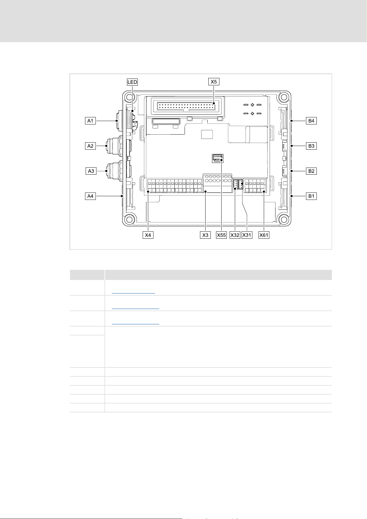
[3-1] EtherCAT Communication Unit
Pos. Description
A1 / LED Position of LEDs for EtherCAT status display
LED status displays
A2 IN: EtherCAT input (M12 socket, 5-pole, D-coded)
EtherCAT connection
A3 OUT: EtherCAT output (M12 socket, 5-pole, D-coded)
EtherCAT connection
A4 Positions for further freely designable inputs and outputs:
B1 ... B4
X3 / X4 / X61 Terminal strips for wiring the connections at A4 and B1 ... B4
X5 Plug connector for connection to the Drive Unit
X31 Plug connector for wiring the EtherCAT input (IN) at A2
X32 Plug connector for wiring the EtherCAT output (OUT) at A3
X55 Plug connector for wiring the LEDs at A1
• Digital inputs
•Digital output
• Analog input (only for E84DGFCTxJx)
• Relay output (only for E84DGFCTxJx)
• Connection of safety system "Safety Option" (only for E84DGFCTxJx)
E84DG029
( 58)
( 23)
( 23)
EDS84DMOTECAT EN 2.1 - 11/2012 L 15
Page 16

Communication manual 8400 motec EtherCAT®
Product description
Connections and interfaces
On delivery, the EtherCAT connections and the LEDs for the EtherCAT status displays
are already mounted and wired:
– EtherCAT input to plug connector X31
– EtherCAT output to plug connector X32
– LEDs to plug connector X55
It is also possible to connect the EtherCAT and other inputs and outputs (e.g. digital
inputs) via the positions A1 ... A4 and B1 ... B4.
For the connections, 5-pin M12 connectors or - alternatively - cable glands (cable cross-
section max. 1.0 mm
The M12 connectors, cable glands and prefabricated system cables can be obtained
from various manufacturers.
Wire the M12 connectors or cable glands used to the corresponding contacts of the
terminal strips/plug connectors X3, X4 and X61.
2
, AWG 18) can be used.
"Inverter Drives 8400 motec" hardware manual
Observe the notes and wiring instructions included.
16 L EDS84DMOTECAT EN 2.1 - 11/2012
Page 17

Communication manual 8400 motec EtherCAT®
4 Technical data
"Inverter Drives 8400 motec" hardware manual
Here you will find the ambient conditions and information on the
electromagnetic compatibility (EMC) that also apply to the Communication
Unit.
4.1 General data and operating conditions
Area Values
Order designation • E84DGFCTxNx (EtherCAT)
• E84DGFCTxJx (EtherCAT + Safety)
Communication profile EtherCAT
Supported device profile and mailbox
protocol
Communication medium S/FTP (Screened Foiled Twisted Pair, ISO/IEC 11801 or EN 50173), CAT 5e
Interface for communication • EtherCAT input (IN): M12 socket, 5-pole, D-coded
Network topology Line, switch
Type of node EtherCAT slave
Number of nodes Max. 65535 ( in the entire network )
Max. cable length between two
EtherCAT nodes
Vendor ID [hex] 0x3B
Product ID 841020
Revision ID Dependent on the software version of the Communication Unit
Baud rate 100 Mbps, full duplex
Cycle times 1 ms or an integer multiple of 1 ms
External voltage supply • U = 24 V DC (20 V - 0 % ... 29 V + 0 %)
Conformities, approvals • CE
CANopen over EtherCAT (CoE)
• EtherCAT output (OUT): M12 socket, 5-pole, D-coded
100 m (typically)
•I
= 400 mA
max
•UR / cUR
Technical data
General data and operating conditions
EDS84DMOTECAT EN 2.1 - 11/2012 L 17
Page 18

Communication manual 8400 motec EtherCAT®
Technical data
Protocol data
4.2 Protocol data
Area Values
Process data words 1 ... 10 process data words to master (max. 20 bytes, 16 bits / word)
1 ... 8 process data words from master (max. 16 bytes, 16 bits / word)
Parameter data (mailbox size for CoE
transfer)
4.3 Communication time
Parameter data (SDO)
The communication time for parameter data is the time between the transmission of an
SDO request and the arrival of a corresponding response.
The processing time in the controller is approx. 10 ms + a tolerance of +20 ms (typically)
Max. 128 bytes
Some codes may require a longer processing time (see software manual / »Engineer«
online help "Inverter Drive 8400 motec").
Process data (PDO)
The communication time for process data is the time between the reception of a PDO with
setpoints and the return of a PDO with current actual values.
The communication times for process data depend on the ...
processing time in the controller (interval time of the application task, process data
mode)
runtime on the bus (telegram length, number of nodes, PDO update time, instant of
transmission of the EtherCAT frame)
The processing time starts when the setpoints are taken over by the controller at a point in
time which is not synchronised with the EtherCAT master, and ends when the current
actual values are provided at the EtherCAT interface.
Hence, the following holds true for the processing time:
1.3 ms + 1.0 ms (tolerance) + interval time of the application task
18 L EDS84DMOTECAT EN 2.1 - 11/2012
Page 19

5 Installation
Stop!
Electrostatic discharge
Electronic components within the Communication Unit can be damaged or
destroyed by electrostatic discharge.
Possible consequences:
• The Communication Unit is defective.
• Fieldbus communication is troubled or not possible.
• I/O signals are faulty.
• The safety function is faulty.
Protective measures
• Discharge electrostatic charges before touching the Communication Unit.
Communication manual 8400 motec EtherCAT®
Installation
EDS84DMOTECAT EN 2.1 - 11/2012 L 19
Page 20
Communication manual 8400 motec EtherCAT®
Installation
Mechanical installation
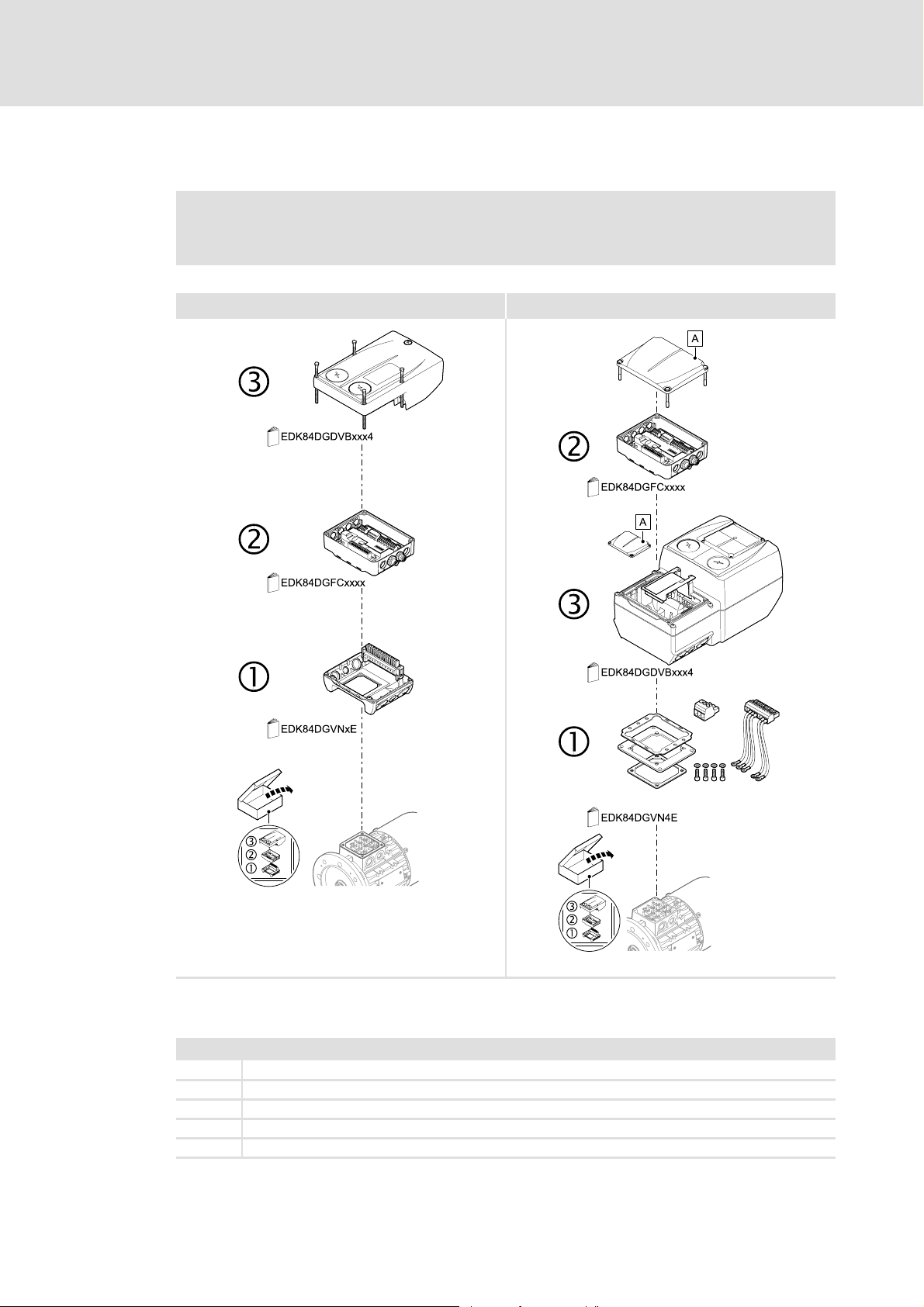
5.1 Mechanical installation
Mounting instructions for "Inverter Drives 8400 motec"
Here you will find detailed information on the installation.
0.37 ... 3.0 kW 4.0 ... 7.5 kW
E84DG023a
E84DG023b
[5-1] Mechanical installation of the 8400 motec components
Legend for Fig. [5-1]
1Drive Unit
2 Communication Unit
3 Wiring Unit
A Cover of the Drive Unit
EDK84DG... Mounting instructions for the Drive Unit, Communication Unit, Wiring Unit
20 L EDS84DMOTECAT EN 2.1 - 11/2012
Page 21

5.2 Electrical installation
"Inverter Drives 8400 motec" hardware manual
Here you will find detailed information about ...
• the digital and analog inputs/outputs;
• the relay output;
• the integrated safety system (safety option);
• the wiring of the connections.
Observe the notes and wiring instructions included.
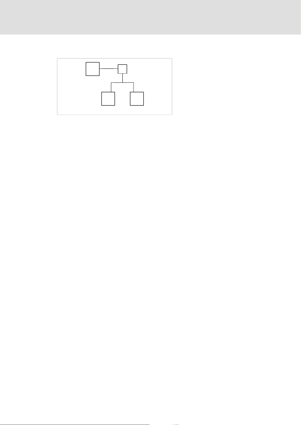
5.2.1 Network topology
An EtherCAT telegram is sent through a pair of wires from the master to the slaves. The
telegram is forwarded from slave to slave until it has passed through all the devices.
Finally, the last slave returns the telegram to the master through a second pair of wires. In
this way, EtherCAT always forms a logic ring topology, independent of the topology
selected.
Communication manual 8400 motec EtherCAT®
Installation
Electrical installation
Line topology
M
[5-2] Line topology
The devices are interconnected successively.
Correct assignment and wiring of the EtherCAT inputs (IN) and EtherCAT outputs (OUT)
is required for proper operation.
The direction of data transmission is from the master to the slaves.
Tip!
The termination of the last node is effected automatically by the slave.
IN
SD
INOUT
SD
INOUT
SD
M = master
SD = slave device
E94AYCET006
EDS84DMOTECAT EN 2.1 - 11/2012 L 21
Page 22
Communication manual 8400 motec EtherCAT®
Installation
Electrical installation
Switch topology
M
M
IN IN
S
M = master
S = switch
SD = slave device
SD
[5-3] Switch topology
The wiring can also be carried out in a star structure via an appropriate switch. For this,
observe the additional runtimes.
SD
E94AYCET007
22 L EDS84DMOTECAT EN 2.1 - 11/2012
Page 23
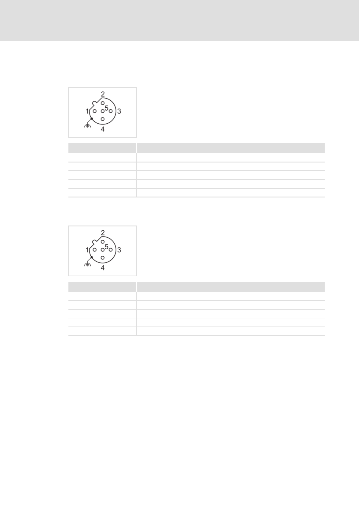
5.2.2 EtherCAT connection
EtherCAT input (IN)
Pin Signal Description
1 Tx + Data line (transmitted data, plus)
2 Rx + Data line (received data, plus)
3 Tx - Data line (transmitted data, minus)
4 Rx - Data line (received data, minus)
5 - Not assigned
Communication manual 8400 motec EtherCAT®
Installation
Electrical installation
M12 socket, 5-pole, D-coded
Wiring at terminal strip X31
EtherCAT output (OUT)
M12 socket, 5-pole, D-coded
Wiring at terminal strip X32
Pin Signal Description
1 Tx + Data line (transmitted data, plus)
2 Rx + Data line (received data, plus)
3 Tx - Data line (transmitted data, minus)
4 Rx - Data line (received data, minus)
5 - Not assigned
EDS84DMOTECAT EN 2.1 - 11/2012 L 23
Page 24

Communication manual 8400 motec EtherCAT®
Installation
Electrical installation
5.2.3 External voltage supply
The external voltage supply can be used to establish EtherCAT communication for
commissioning purposes and to query the data of the digital and analog inputs.
Moreover, the external voltage supply serves to keep up EtherCAT communication in
the event of a main supply failure.
The digital inputs RFR, DI1 ... DI5 and the analog inputs can be evaluated as before.
The external voltage supply is done via the terminals 24E and GND of the terminal strip
X3.
Permissible voltage (DC) / max. current:
– U = 24 V DC (20 V - 0 % ... 29 V + 0 %)
–I
Access to parameters of a device that is disconnected from the mains is not possible.
= 400 mA
max
"Inverter Drives 8400 motec" hardware manual
Here you can find detailed information on how to wire the Communication Unit.
24 L EDS84DMOTECAT EN 2.1 - 11/2012
Page 25

6 Commissioning
During commissioning, system-related data such as motor parameters, operating
parameters, responses, and parameters for fieldbus communication are defined for the
controller. For Lenze devices, this is done via the codes.
The codes of the controller and communication are saved non-volatilely as a data set in the
memory module.
In addition to codes for the configuration, there are codes for diagnosing and monitoring
the nodes.
Communication manual 8400 motec EtherCAT®
Commissioning
Before initial switch-on
Parameter reference
The data from the controller or memory module can only be read in conjunction with the
main voltage supply (400/500 V AC).
During commissioning with 24 V DC, only the information provided by the last two data
words in the digital and analog inputs is valid and readable (see Configuring process data
( 28)).
6.1 Before initial switch-on
Stop!
Before the controller is switched on for the first time, the entire wiring must be
checked for completeness, short circuit and earth fault.
( 66)
EDS84DMOTECAT EN 2.1 - 11/2012 L 25
Page 26

Communication manual 8400 motec EtherCAT®
Commissioning
Configuring the host (master)
6.2 Configuring the host (master)
To be able to communicate with the Communication Unit the host (master) must be
configured first.
In order to configure EtherCAT networks, you always need a configuration software for the
host (master), e.g.:
Lenze »PLC Designer«
Beckhoff »TwinCAT«
These are software systems for the programming of control programs, EtherCAT
configuration, real-time execution and diagnostics.
The basic parameters of the Communication Unit are saved to the internal
configuration memory and can be used by the master for the node identification.
For the node search (fieldbus scan), the corresponding device descriptions of the Lenze
device family are used.
6.2.1 Installing device description files
The current XML device description files required for the configuration of the EtherCAT
node can be found in the download area at:
www.Lenze.com
The Lenze_E84DGFCT_Vxzz_ddmmyy.xml device description file must be installed by
means of the EtherCAT configuration software.
Wildcards in the file name
x Main version of the XML device description file used
zz Additional version of the XML device description file used
dd Day
mm Month
yy Year
26 L EDS84DMOTECAT EN 2.1 - 11/2012
Page 27

Communication manual 8400 motec EtherCAT®
6.2.2 Automatic device identification
For troublefree integration of the EtherCAT slaves in a master configuration it is
necessary to select the correct Lenze device from the EtherCAT configuration software.
The configuration software unambiguously identifies an EtherCAT node by the product
code (identical to CoE object I-1018.2), the manufacturer code (0x3B), and the main
software version of the Communication Unit.
Implemented CoE objects
The product code is automatically set in the Identity object for the configuration
software to select the configuration specific to the EtherCAT node from the device
description file.
During initialisation, the product code is transferred to the master. Based on this
identification, the master can accept the corresponding settings from the device
description.
Product code of the Inverter Drives 8400 motec: 841020
Commissioning
Configuring the host (master)
( 53)
EDS84DMOTECAT EN 2.1 - 11/2012 L 27
Page 28

Communication manual 8400 motec EtherCAT®
Commissioning
Configuring the host (master)
6.2.3 Configuring process data
The process data configuration is determined during the initialisation phase of the
master (PDO mapping).
A maximum of 10 process data words (max. 20 bytes) can be sent to the master.
A maximum of 8 process data words (max. 16 bytes) can be sent by the master.
Independent of the configured length of the process data from the Inverter Drive 8400
motec to the master, the I/O data are always entered into the last two words:
Data word Bits Function Value / description
Word 1 0
...
9
10 Digital input 3 0 (FALSE) open
11 Digital input 4 0 (FALSE) open
12 Digital input 5 0 (FALSE) open
13 Reserved
14 I/O status 0 (FALSE) Data in word 1/2 are not valid.
15 Connection status of the
Analog input value
(0 ... 10 V)
controller
Word 2 0 RFR 0 (FALSE) open
1 Digital input 1 0 (FALSE) open
2 Digital input 2 0 (FALSE) open
3 Digital input 3 0 (FALSE) open
4 Digital input 4 0 (FALSE) open
5 Digital input 5 0 (FALSE) open
6
...
13
14 I/O status 0 (FALSE) Data in word 1/2 are not valid.
15 Connection status of the
Reserved
controller
10 V = 1000
1 (TRUE) closed
1 (TRUE) closed
1 (TRUE) closed
1 (TRUE) Data in word 1/2 are valid.
0 (FALSE) Controller is offline ("Stay alive" operation)
1 (TRUE) Controller is online
1 (TRUE) closed
1 (TRUE) closed
1 (TRUE) closed
1 (TRUE) closed
1 (TRUE) closed
1 (TRUE) closed
1 (TRUE) Data in word 1/2 are valid.
0 (FALSE) Controller is offline ("Stay alive" operation)
1 (TRUE) Controller is online
28 L EDS84DMOTECAT EN 2.1 - 11/2012
Page 29

The process data configuration is predefined in the device description file for each
application and can be adjusted by the user if required.
Configuring the port interconnection of the process data objects (PDO)
The last internal information of the configured data must be deleted to shorten the
configured length of the process data. Process data words to the master must keep
their last two I/O data words.
6.2.4 Determining the cycle time
The process data objects (PDO) are transmitted cyclically between the master and the
slaves.
The cycle time can be set via the EtherCAT configuration software.
Communication manual 8400 motec EtherCAT®
Commissioning
Configuring the host (master)
( 39)
EDS84DMOTECAT EN 2.1 - 11/2012 L 29
Page 30

Communication manual 8400 motec EtherCAT®
Commissioning
Address allocation
6.3 Address allocation
The EtherCAT nodes are normally addressed via a fixed 16-bit address defined by the
EtherCAT master. During start-up, the master assigns this address to each node, depending
on the physical order in the EtherCAT network. The address is not saved and is lost when
the device is switched off.
Via the Station alias address input field you can assign a fixed address to the EtherCAT
slave.
Note!
• The station alias address must only be set if the node is part of a "hot connect"
group.
• The station alias address must be unambiguous and may only be assigned
once within the EtherCAT network.
• Use the same station alias address in the EtherCAT master and in the slave.
Valid address range: 0 … 32767
– Address 0 means that no station alias address is assigned.
– Impermissible addresses are marked in red in the input field.
– The address is written to code C13899
In addition, specify the use of the fixed addressing on the master.
The address assigned by the master is displayed under code C13864
Via standard device code C00002, execute the "11: Save all parameter sets" device
command to activate the changed station alias address and to save it to the memory
module.
.
.
30 L EDS84DMOTECAT EN 2.1 - 11/2012
Page 31

6.4 Initial switch-on
Establishing communication
To establish communication, the controller must be supplied with mains voltage.
The external voltage supply serves to keep up EtherCAT communication in the event of
a main supply failure.
External voltage supply
During mains connection, all parameters (codes) are read.
If an error occurs, the error message "CE04: MCI communication error" (error no.
01.0127.00002) is output.
Addressing can be carried out automatically via the EtherCAT master or manually via
codes in the »Engineer«.
Address allocation
Communication manual 8400 motec EtherCAT®
Commissioning
Initial switch-on
( 24)
( 30)
EDS84DMOTECAT EN 2.1 - 11/2012 L 31
Page 32

Communication manual 8400 motec EtherCAT®
Data transfer
7 Data transfer
EtherCAT transmits data in so-called "EtherCAT frames". The EtherCAT nodes only extract
the data intended for them while the EtherCAT frame passes through the device. At the
same time output data are inserted into the frame while it passes through the device. Read
and write accesses are only executed on a small section of the entire EtherCAT frames – the
datagrams. Therefore it is not necessary to receive the complete frame before it can be
processed. The processing starts as soon as possible.
EtherCAT transmits process data, parameter data, configuration data, and diagnostic data
between the host (master) and the controllers (slaves) that are part of the fieldbus. The
data are transmitted via corresponding communication channels depending on their timecritical behaviour (see Process data transfer
( 37) / Parameter data transfer ( 43)).
32 L EDS84DMOTECAT EN 2.1 - 11/2012
Page 33

7.1 EtherCAT frame structure
EtherCAT frames have the following structure:
Ethernet header Ethernet data FCS
48 bits 48 bits 16 bits 11 bits 1 bit 4 bits 48 ... 1498 bytes 32 bits
Destination Source EtherType Frame header Datagrams
Ethernet header
The Ethernet header contains the following information:
Target address of the EtherCAT frame (destination)
Source address of the EtherCAT frame (source)
Type of the EtherCAT frame (EtherType = 0x88A4)
Ethernet data
Communication manual 8400 motec EtherCAT®
Data transfer
EtherCAT frame structure
Length Reserved Type
The Ethernet data contain the following information:
Length of the datagrams within the EtherCAT frame (Length)
One reserved bit (Reserved)
Type of the datagrams within the EtherCAT frame (Type)
EtherCAT datagrams (Datagrams)
FCS
Checksum of the EtherCAT frame
EDS84DMOTECAT EN 2.1 - 11/2012 L 33
Page 34

Communication manual 8400 motec EtherCAT®
Data transfer
EtherCAT datagrams
7.2 EtherCAT datagrams
EtherCAT datagrams have the following structure:
EtherCAT
Command header
10 bytes Max. 1486 bytes 2 bytes
EtherCAT command header
The EtherCAT command header contains the following information:
Command to be executed
Addressing information
Length of the data area (Data)
Interrupt field
Data
The data area contains the data of the command to be executed.
WKC
The working counter is evaluated by the master for monitoring the execution of the
command.
Data WKC
34 L EDS84DMOTECAT EN 2.1 - 11/2012
Page 35

7.3 EtherCAT state machine
Before communication is possible via EtherCAT, the fieldbus passes through the EtherCAT
state machine during start-up. The following illustration depicts the possible state
changes from the point of view of an EtherCAT slave:
Communication manual 8400 motec EtherCAT®
Data transfer
EtherCAT state machine
Init
Pre-Operational
Safe-Operational
Operational
[7-1] EtherCAT state machine
Status Description
Init • Initialisation phase
• No SDO/PDO communication with the slave
• Device detection possible by means of a fieldbus scan
Pre-operational • The fieldbus is active.
• SDO communication (mailbox communication) is possible.
• No PDO communication
Safe-operational • SDO communication (mailbox communication) is possible.
• PDO communication:
–The input data are transferred to the master and evaluated.
– The output data are in the "Safe" state. They are not transferred to the standard
device.
Operational • Normal operation
–SDO communication
–PDO communication
–Fieldbus synchronisation successful (if used)
The current state of the EtherCAT state machine is displayed under C13861 and indicated
via the "RUN" LED.
E94AYCET009
Possible errors during state transitions are displayed in C13879
message is entered into the "AL Status Code" EtherCAT register
Diagnostics with the »Engineer«
LED status displays
EDS84DMOTECAT EN 2.1 - 11/2012 L 35
( 58)
( 60)
. In addition, an error
( 36).
Page 36

Communication manual 8400 motec EtherCAT®
Data transfer
EtherCAT state machine
AL Status Code
Information on how to access the "AL Status Code" EtherCAT register (address
0x0134:0x0135) can be found in the documentation for the EtherCAT master.
These error messages can be entered into the "AL Status Code" register:
Code [hex] Description
0x0000 No error
0x0011 Invalid status change requested
0x0012 Unknown status requested
0x0013 "Bootstrap" status is not supported
0x0016 Invalid mailbox configuration "Pre-operational"
0x001A Synchronisation error
0x001B Sync manager watchdog
0x001D Invalid output data configuration
0x001E Invalid input data configuration
0x002B Invalid input and output data
0x0030 Invalid configuration of DC synchronisation
0x9001 Firmware watchdog error
0x9002 Mapping error
36 L EDS84DMOTECAT EN 2.1 - 11/2012
Page 37

8 Process data transfer
Process data are transmitted by means of so-called EtherCAT datagrams ( 34) via the
process data channel.
The Inverter Drive 8400 motec is controlled by means of the process data.
Transferring process data is time-critical.
Process data are cyclically transferred between the host (master) and the controllers
(slaves) (continuous exchange of current input and output data).
The master can directly access the process data. In the PLC for instance, the data are
directly stored in the I/O area.
A maximum of 10 process data words (max. 20 bytes) can be sent to the master.
A maximum of 8 process data words (max. 16 bytes) can be sent by the master.
Process data are not saved to the Inverter Drive 8400 motec.
Process data are for instance setpoints, actual values, control words, and status words.
Communication manual 8400 motec EtherCAT®
Process data transfer
EDS84DMOTECAT EN 2.1 - 11/2012 L 37
Page 38

Communication manual 8400 motec EtherCAT®
Process data transfer
Accessing process data / PDO mapping
8.1 Accessing process data / PDO mapping
Process data are transferred via the MCI/CAN interface.
Max. 8 words (16 bits/word) per direction can be exchanged.
The process data are accessed via the port blocks LP_Network_In and
LP_Network_Out. These port blocks are also called process data channels.
The LP_Network_In port block maps the received MCI-PDOs.
The LP_Network_Out port block maps the MCI-PDOs to be sent.
The port/function block interconnection of the process data objects (PDOs) is made via
the Lenze »Engineer«.
[8-1] Outer and inner data transfer between bus system, controller, and application
Software manual / »Engineer« online help "Inverter Drives 8400 motec"
Here you can find detailed information on the port/function block
interconnection in the »Engineer« and on port blocks.
38 L EDS84DMOTECAT EN 2.1 - 11/2012
Page 39

Communication manual 8400 motec EtherCAT®
Process data transfer
Configuring the port interconnection of the process data objects (PDO)
8.2 Configuring the port interconnection of the process data objects (PDO)
Note!
The following »Engineer« screenshots are only examples of the setting sequence
and the resulting displays.
Depending on the software version of the controller and of the installed
»Engineer« software, the screenshots may vary from your »Engineer« depiction.
The preconfigured port interconnection of the process data objects is activated by setting
code C00007 = 40: Network (MCI/CAN).
How to configure the port interconnection in the »Engineer«:
1. Go to the Process data objects tab and click Go to application.
2. The Ports tab displays the port blocks MCI_IN and MCI_OUT.
EDS84DMOTECAT EN 2.1 - 11/2012 L 39
Page 40

Communication manual 8400 motec EtherCAT®
Process data transfer
Configuring the port interconnection of the process data objects (PDO)
3. Click the port to be configured and press the Change Variable... button.
40 L EDS84DMOTECAT EN 2.1 - 11/2012
Page 41

Communication manual 8400 motec EtherCAT®
Process data transfer
Configuring the port interconnection of the process data objects (PDO)
4. The button serves to assign signals to the process data words in the Assignment
Signal --> Function Block dialog box.
Select signals and then click the OK button.
EDS84DMOTECAT EN 2.1 - 11/2012 L 41
Page 42

Communication manual 8400 motec EtherCAT®
Process data transfer
Configuring the port interconnection of the process data objects (PDO)
For some process data words, you can also assign signals to the individual bits via
the and buttons.
Select the signals and then confirm the selection with OK.
The current interconnection is only displayed if the following has been set for the
control mode in code C00007 = 40: Network (MCI/CAN).
5. Via standard device code C00002, execute the "11: Save all parameter sets" device
command to activate the changed port interconnection and to save it to the
memory module.
42 L EDS84DMOTECAT EN 2.1 - 11/2012
Page 43

Communication manual 8400 motec EtherCAT®
9 Parameter data transfer
Parameter data are transmitted via the fieldbus as so-called SDOs (Service Data Objects).
The SDO services provide for the write and read access to the object directory.
Parameter data transfer
Establishing a connection between master and slave
The SDO channel provides for the access to Implemented CoE objects
codes by means of the CoE protocol.
In general, the parameter data transfer is not time-critical.
Parameter data are, for instance, operating parameters, motor data, diagnostic
information.
9.1 Establishing a connection between master and slave
Basically a master can always request parameter jobs from a slave if the slave is at least in
the "Pre-operational" state.
SDO-channel
Master
[9-1] Data communication via the SDO channel
read
write
( 53) and Lenze
Slave
E94AYCET008
EDS84DMOTECAT EN 2.1 - 11/2012 L 43
Page 44

Communication manual 8400 motec EtherCAT®
Parameter data transfer
Reading and writing parameters
9.2 Reading and writing parameters
Parameters ...
are set e.g. for one-time system settings or if materials are changed within a machine.
are transmitted with a low priority.
In the case of Lenze controllers, the parameters to be changed are contained in codes.
Indexing of the Lenze codes
The codes of the Inverter Drive 8400 motec are addressed by the index when accessed via
the Communication Unit.
The index of Lenze code numbers within the manufacturer-specific area of the object
directory is between 8192 (0x2000) and 24575 (0x5FFF).
Conversion formula
Index [dec] Index [hex]
24575 - Lenze code 0x5FFF
- Lenze code
hex
Example of C00002 (device commands)
Index [dec] Index [hex]
24575 - 2 = 24573 0x5FFF - 2 = 0x5FFD
Structure of a mailbox datagram
Mailbox data are transmitted in a datagramm within an EtherCAT frame. The data area of
the mailbox datagram has the following structure:
Mailbox
Header
6 bytes 2 bytes 1 byte 2 bytes 1 byte 4 bytes 1...n bytes
CoE
Header
SDO control
byte
Index Subindex Data Data
44 L EDS84DMOTECAT EN 2.1 - 11/2012
Page 45

Communication manual 8400 motec EtherCAT®
9.2.1 Reading parameters (SDO Upload)
1. The master sends "Initiate Domain Upload Request".
2. The slave acknowledges the request with a positive response ("Initiate Domain Upload
Response").
In the event of an error the slave responds with "Abort Domain Transfer".
Note!
In the case of jobs for the controller, please make sure that you convert the code
into an index.
Parameter data transfer
Reading and writing parameters
Indexing of the Lenze codes
( 44)
SDO Upload Request
Detailed breakdown of the data for an "SDO Upload Request":
SDO frame area Data field Data type / length Value / description
Mailbox header Length WORD 2 bytes 0x0A: Length of the mailbox service data
Address WORD 2 bytes Station address of the source if an EtherCAT master is the
Channel WORD 6 bits (0 ... 5) 0x00: Reserved
Priority 2 bits (6, 7) 0x00: Lowest priority
Type 4 bits (8 ... 11) 0x03: CANopen over EtherCAT (CoE)
Reserved 4 bits (12 ... 15) 0x00
CANopen header Number WORD 9 bits (0 ... 8) 0x00
Reserved 3 bits (9 ... 11) 0x00
Service 4 bits (12 ... 15) 0x02: SDO Request
SDO Reserved BYTE 4 bits (0 ... 3) 0x00
Complete access 1 bit (4) 0x00: The entry addressed by index and subindex is read.
Command specifier 3 bits (5 ... 7) 0x02: Upload Request
Index WORD 2 bytes Index of the object
Subindex BYTE 1 byte Subindex of the object
Reserved DWORD 4 bytes 0x00
instructing party.
Station address of the target if an EtherCAT slave is the
instructing party.
...
0x03: Highest priority
0x01: The entire object is read. (Is not supported at
present.)
0x00 or 0x01 if "Complete access" = 0x01.
EDS84DMOTECAT EN 2.1 - 11/2012 L 45
Page 46

Communication manual 8400 motec EtherCAT®
Parameter data transfer
Reading and writing parameters
SDO Upload Expedited Response
An "SDO Upload Expedited Response" is carried out if the data length of the parameter
data to be read amounts to a maximum of 4 bytes.
Detailed breakdown of the data for an "SDO Upload Expedited Response":
SDO frame area Data field Data type / length Value / description
Mailbox header Length WORD 2 bytes 0x0A: Length of the mailbox service data
Address WORD 2 bytes Station address of the source if an EtherCAT master is the
Channel WORD 6 bits (0 ... 5) 0x00: Reserved
Priority 2 bits (6, 7) 0x00: Lowest priority
Type 4 bits (8 ... 11) 0x03: CANopen over EtherCAT (CoE)
Reserved 4 bits (12 ... 15) 0x00
CANopen header Number WORD 9 bits (0 ... 8) 0x00
Reserved 3 bits (9 ... 11) 0x00
Service 4 bits (12 ... 15) 0x03: SDO Response
SDO Size indicator BYTE 1 bit (0) 0x01: Data size in "Data set size"
Transfer type 1 bit (1) 0x01: Expedited transfer
Data set size 2 bits (2, 3) 0x00: 4 bytes data
Complete access 1 bit (4) 0x00: The entry addressed by index and subindex is read.
Command specifier 3 bits (5 ... 7) 0x02: Upload Response
Index WORD 2 bytes Index of the object
Subindex BYTE 1 byte Subindex of the object
Data DWORD 4 bytes Data of the object
instructing party.
Station address of the target if an EtherCAT slave is the
instructing party.
...
0x03: Highest priority
0x01: 3 bytes data
0x02: 2 bytes data
0x03: 1 byte data
0x01: The entire object is read. (Is not supported at
present.)
0x00 or 0x01 if "Complete access" = 0x01.
46 L EDS84DMOTECAT EN 2.1 - 11/2012
Page 47

Communication manual 8400 motec EtherCAT®
Parameter data transfer
Reading and writing parameters
SDO Upload Normal Response
An "SDO Upload Normal Response" is carried out if the data length of the parameter data
to be read amounts to ≥ 4bytes.
Detailed breakdown of the data for an "SDO Upload Normal Response":
SDO frame area Data field Data type / length Value / description
Mailbox header Length WORD 2 bytes n ≥ 0x0A: Length of the mailbox service data
Address WORD 2 bytes Station address of the source if an EtherCAT master is the
Channel WORD 6 bits (0 ... 5) 0x00: Reserved
Priority 2 bits (6, 7) 0x00: Lowest priority
Type 4 bits (8 ... 11) 0x03: CANopen over EtherCAT (CoE)
Reserved 4 bits (12 ... 15) 0x00
CANopen header Number WORD 9 bits (0 ... 8) 0x00
Reserved 3 bits (9 ... 11) 0x00
Service 4 bits (12 ... 15) 0x03: SDO Response
SDO Size indicator BYTE 1 bit (0) 0x01
Transfer type 1 bit (1) 0x00: Normal transfer
Data set size 2 bits (2, 3) 0x00
Complete access 1 bit (4) 0x00: The entry addressed by index and subindex is read.
Command specifier 3 bits (5 ... 7) 0x02: Upload Response
Index WORD 2 bytes Index of the object
Subindex BYTE 1 byte Subindex of the object
Complete size DWORD 4 bytes Total data length of the object
Data BYTE n - 10 bytes Data of the object
instructing party.
Station address of the target if an EtherCAT slave is the
instructing party.
...
0x03: Highest priority
0x01: The entire object is read. (Is not supported at
present.)
0x00 or 0x01 if "Complete access" = 0x01.
EDS84DMOTECAT EN 2.1 - 11/2012 L 47
Page 48

Communication manual 8400 motec EtherCAT®
Parameter data transfer
Reading and writing parameters
Example
The transmitted response structure during an Upload to index 0x5FD8 (standard value of
C00039/1, Fixed_Setpoint_1 = 0x0FA0) includes the following data:
SDO frame area Data field Data type / length Value / description
Mailbox header Length WORD 2 bytes 0x0A: Length of the mailbox service data
Address WORD 2 bytes 0x00
Channel WORD 6 bits (0 ... 5) 0x00: Reserved
Priority 2 bits (6, 7) 0x00: Lowest priority
Type 4 bits (8 ... 11) 0x03: CANopen over EtherCAT (CoE)
Reserved 4 bits (12 ... 15) 0x00
CANopen header Number WORD 9 bits (0 ... 8) 0x00
Reserved 3 bits (9 ... 11) 0x00
Service 4 bits (12 ... 15) 0x03: SDO Response
SDO Size indicator BYTE 1 bit (0) 0x01: Data length in "Data set size"
Transfer type 1 bit (1) 0x01: Expedited transfer
Data set size 2 bits (2, 3) 0x02: 2 bytes data
Complete access 1 bit (4) 0x00: The entry addressed by index and subindex is read.
Command specifier 3 bits (5 ... 7) 0x02: Upload Response
Index WORD 2 bytes 0xD8: Index low byte of the object
Subindex BYTE 1 byte 0x01
Data DWORD 2 bytes 0x0FA0
0x5F: Index high byte of the object
48 L EDS84DMOTECAT EN 2.1 - 11/2012
Page 49

Communication manual 8400 motec EtherCAT®
9.2.2 Writing parameters (SDO Download)
1. The master sends "Initiate Domain Download Request".
2. The slave acknowledges the request with a positive response ("Initiate Domain
Download Response").
In the event of an error the slave responds with "Abort Domain Transfer".
Note!
In the case of jobs for the controller, please make sure that you convert the code
into an index.
Parameter data transfer
Reading and writing parameters
Indexing of the Lenze codes
( 44)
SDO Download Expedited Request
An "SDO Download Expedited Request" is carried out if the data length of the parameter
data to be written amounts to a maximum of 4 bytes.
Detailed breakdown of the data for an "SDO Download Expedited Request":
SDO frame area Data field Data type / length Value / description
Mailbox header Length WORD 2 bytes 0x0A: Length of the mailbox service data
Address WORD 2 bytes Station address of the source if an EtherCAT master is the
Channel WORD 6 bits (0 ... 5) 0x00: Reserved
Priority 2 bits (6, 7) 0x00: Lowest priority
Type 4 bits (8 ... 11) 0x03: CANopen over EtherCAT (CoE)
Reserved 4 bits (12 ... 15) 0x00
CANopen header Number WORD 9 bits (0 ... 8) 0x00
Reserved 3 bits (9 ... 11) 0x00
Service 4 bits (12 ... 15) 0x02: SDO Request
SDO Size indicator BYTE 1 bit (0) 0x01: Data size in "Data set size"
Transfer type 1 bit (1) 0x01: Expedited transfer
Data set size 2 bits (2, 3) 0x00: 4 bytes data
Complete access 1 bit (4) 0x00: The entry addressed by index and subindex is
Command specifier 3 bits (5 ... 7) 0x01: Download Request
Index WORD 2 bytes Index of the object
Subindex BYTE 1 byte Subindex of the object
Data DWORD 4 bytes Data of the object
instructing party.
Station address of the target if an EtherCAT slave is the
instructing party.
...
0x03: Highest priority
0x01: 3 bytes data
0x02: 2 bytes data
0x03: 1 byte data
written.
0x01: The entire object is written. (Is not supported at
present.)
0x00 or 0x01 if "Complete access" = 0x01.
EDS84DMOTECAT EN 2.1 - 11/2012 L 49
Page 50

Communication manual 8400 motec EtherCAT®
Parameter data transfer
Reading and writing parameters
SDO Download Normal Request
An "SDO Download Normal Request" is carried out if the data length of the parameter data
to be written amounts to ≥ 4bytes.
Detailed breakdown of the data for an "SDO Download Normal Request":
SDO frame area Data field Data type / length Value / description
Mailbox header Length WORD 2 bytes n ≥ 0x0A: Length of the mailbox service data
Address WORD 2 bytes Station address of the source if an EtherCAT master is the
Channel WORD 6 bits (0 ... 5) 0x00: Reserved
Priority 2 bits (6, 7) 0x00: Lowest priority
Type 4 bits (8 ... 11) 0x03: CANopen over EtherCAT (CoE)
Reserved 4 bits (12 ... 15) 0x00
CANopen header Number WORD 9 bits (0 ... 8) 0x00
Reserved 3 bits (9 ... 11) 0x00
Service 4 bits (12 ... 15) 0x02: SDO Request
SDO Size indicator BYTE 1 bit (0) 0x01
Transfer type 1 bit (1) 0x00: Normal transfer
Data set size 2 bits (2, 3) 0x00
Complete access 1 bit (4) 0x00: The entry addressed by index and subindex is
Command specifier 3 bits (5 ... 7) 0x01: Download Request
Index WORD 2 bytes Index of the object
Subindex BYTE 1 byte Subindex of the object
Complete size DWORD 4 bytes Total data length of the object
Data BYTE n - 10 bytes Data of the object
instructing party.
Station address of the target if an EtherCAT slave is the
instructing party.
...
0x03: Highest priority
written.
0x01: The entire object is written. (Is not supported at
present.)
0x00 or 0x01 if "Complete access" = 0x01.
50 L EDS84DMOTECAT EN 2.1 - 11/2012
Page 51

Communication manual 8400 motec EtherCAT®
Parameter data transfer
Reading and writing parameters
SDO Download Response
Detailed breakdown of the data for an "SDO Download Response":
SDO frame area Data field Data type / length Value / description
Mailbox header Length WORD 2 bytes 0x0A: Length of the mailbox service data
Address WORD 2 bytes Station address of the source if an EtherCAT master is the
Channel WORD 6 bits (0 ... 5) 0x00: Reserved
Priority 2 bits (6, 7) 0x00: Lowest priority
Type 4 bits (8 ... 11) 0x03: CANopen over EtherCAT (CoE)
Reserved 4 bits (12 ... 15) 0x00
CANopen header Number WORD 9 bits (0 ... 8) 0x00
Reserved 3 bits (9 ... 11) 0x00
Service 4 bits (12 ... 15) 0x03: SDO Response
SDO Size indicator BYTE 1 bit (0) 0x0
Transfer type 1 bit (1) 0x0
Data set size 2 bits (2, 3) 0x0
Complete access 1 bit (4) 0x00: The entry addressed by index and subindex is
Command specifier 3 bits (5 ... 7) 0x3: Download Response
Index WORD 2 bytes Index of the object
Subindex BYTE 1 byte Subindex of the object
Reserved DWORD 4 bytes 0x00
instructing party.
Station address of the target if an EtherCAT slave is the
instructing party.
...
0x03: Highest priority
written.
0x01: The entire object is written. (Is not supported at
present.)
0x00 or 0x01 if "Complete access" = 0x01.
EDS84DMOTECAT EN 2.1 - 11/2012 L 51
Page 52

Communication manual 8400 motec EtherCAT®
Parameter data transfer
Reading and writing parameters
Example
The transmitted request structure during a Download to index 0x1600 includes the
following data:
SDO frame area Data field Data type / length Value / description
Mailbox header Length WORD 2 bytes 0x0A: Length of the mailbox service data
Address WORD 2 bytes 0x00
Channel WORD 6 bits (0 ... 5) 0x00: Reserved
Priority 2 bits (6, 7) 0x00: Lowest priority
Type 4 bits (8 ... 11) 0x03: CANopen over EtherCAT (CoE)
Reserved 4 bits (12 ... 15) 0x00
CANopen header Number WORD 9 bits (0 ... 8) 0x00
Reserved 3 bits (9 ... 11) 0x00
Service 4 bits (12 ... 15) 0x02: SDO Request
SDO Size indicator BYTE 1 bit (0) 0x01: Data size in "Data set size"
Transfer type 1 bit (1) 0x01: Expedited transfer
Data set size 2 bits (2, 3) 0x00: 4 bytes data
Complete access 1 bit (4) 0x00: The entry addressed by index and subindex is
Command specifier 3 bits (5 ... 7) 0x01: Download Request
Index WORD 2 bytes 0x00: Index low byte of the object
Subindex BYTE 1 byte 0x01: Subindex of the object
Data DWORD 4 bytes 0x5C930110
written.
0x16: Index high byte of the object
52 L EDS84DMOTECAT EN 2.1 - 11/2012
Page 53

9.3 Implemented CoE objects
Lenze devices can be parameterised with both Lenze codes and the manufacturerindependent "CoE objects". In order to comply fully with EtherCAT communication, you
may only use the CoE objects for parameterisation. The CoE objects described in this
manual are defined in the "EtherCAT Specification, Part 6 – Application Layer Protocol
Specification".
Index Designation Subindex Subindex name Type Bits Access
0x1000 Device type - - UDINT 32 R
0x1001 Error register - - USINT 8 R
0x1008 Device name - - STRING(8) 64 R
0x1009 Hardware version - - STRING(8) 64 R
0x100A Software version - - STRING(7) 56 R
0x1018 Identity 0 Number of elements USINT 8 R
0x1600 RxPDO 1 0 Number of elements USINT 8 RW
0x1A00 TxPDO 1 0 Number of elements USINT 8 RW
0x1C00 Sync Man Communication type 0 Number of elements USINT 8 R
0x1C10 Sync Man 0 Assignment 0 - UINT 16 R
0x1C11 Sync Man 1 Assignment 0 - UINT 16 R
0x1C12 Sync Man 2 Assignmen t 0 Number of assigned RxPDOs USINT 8 R
0x1C13 Sync Man 3 Assignmen t 0 Number of assigned TxPDOs USINT 8 R
0x1C32 Sync Man 2 Synchronization 0 Number of elements USINT 8 R
0x1C33 Sync Man 3 Synchronization 0 Number of elements USINT 8 R
Communication manual 8400 motec EtherCAT®
Parameter data transfer
Implemented CoE objects
1 Vendor ID UDINT 32 R
2 Product code UDINT 32 R
3 Revision number UDINT 32 R
4 Serial number UDINT 32 R
1 … 8 Output object 1 … 8 UDINT 32 RW
1 … 10 Input object 1 … 10 UDINT 32 RW
1Elements UDINT32R
1 PDO Mapping object index of
1 PDO Mapping object index of
1 Synchronization type UINT 16 R
2Cycle time / ns UDINT32R
3 Shift time / ns UDINT 32 R
4 Sync types supported UINT 16 R
5 Minimum cycle time / ns UDINT 32 R
6 Minimum shift time / ns UDINT 32 R
1 Synchronization type UINT 16 R
2Cycle time / ns UDINT32R
3 Shift time / ns UDINT 32 R
4 Sync types supported UINT 16 R
5 Minimum cycle time / ns UDINT 32 R
6 Minimum shift time / ns UDINT 32 R
assigned RxPDO
assigned TxPDO
UDINT 32 R
UDINT 32 R
R: Read access only
RW: Read and write access
EDS84DMOTECAT EN 2.1 - 11/2012 L 53
Page 54

Communication manual 8400 motec EtherCAT®
Parameter data transfer
EtherCAT objects of the Communication Unit
9.4 EtherCAT objects of the Communication Unit
The object directory displays the Parameters relevant for EtherCAT communication
( 67)
as objects:
Index Code Index name Subindex Subindex name Type Bits Access
0x29E5 C13850 All words from drive to master 0 ... 10 All words from drive to master UNSIGNED 16 R
0x29E4 C13851
0x29DC C13859
0x29DB C13860
0x29DA C13861
0x29D7 C13864
0x29D4 C13867
0x29C8 C13879
0x29C7 C13880
0x29C6 C13881
0x29C2 C13885
0x29B4 C13899
0x29B3 C13900
0x29B2 C13901
0x29B1 C13902
R: Read access only
RW: Read and write access
All words from master to drive 0 ... 8 All words from master to drive UNSIGNED 16 R
Number of PDO words Tx - - UNSIGNED 16 R
Number of PDO words Rx - - UNSIGNED 16 R
Bus state - - UNSIGNED 16 R
Active station address - - UNSIGNED 16 R
Display last emergency data - - STRING(8) 64 R
Bus error - - UNSIGNED 16 R
Reaction on communication
failure
Monitoring time com. failure - - UNSIGNED 16 RW
Clear process data - - UNSIGNED 8 RW
Station Alias address - - UNSIGNED 16 RW
Firmware product type - - STRING(8) 64 R
Firmware compilation date - - STRING(20) 160 R
Firmware version - - STRING(11) 88 R
1- UNSIGNED8RW
54 L EDS84DMOTECAT EN 2.1 - 11/2012
Page 55

Communication manual 8400 motec EtherCAT®
9.5 SDO abort codes (Abort codes)
If an SDO request is evaluated negatively, a corresponding error code is output.
Index [hex] Description
0x00000000 No error
0x05030000 The status of the toggle bit has not changed
0x05040000 SDO time-out protocol
0x05040001 Invalid or unknown specification symbol for the client/server command
0x05040005 Not enough space in the main memory
0x06010000 Non-supported access to an object
0x06010001 Read access to a write-protected object
0x06010002 Write access to a write-protected object
0x06020000 An object does not exist in the object directory
0x06040041 An object cannot be mapped into the PDO
0x06040042 The number and/or length of the objects mapped would exceed the PDO length
0x06040043 General parameter incompatibility
0x06040047 General internal incompatibility within the device
0x06060000 Access has failed due to a fault in the hardware
0x06070010 The data type or the parameter length does not correspond
0x06070012 Incorrect data type (The parameter length is too large)
0x06070013 Incorrect data type (The parameter length is too small)
0x06090011 A subindex is not available
0x06090030 The value range for parameters is too great (only for write access)
0x06090031 The parameter value is too high
0x06090032 The parameter value is too low
0x06090036 The maximum value is lower than the minimum value
0x08000000 General error
0x08000020 Data cannot be transferred to the application or stored in the application
0x08000021 Due to local control, data cannot be transferred to the application or stored in the
application
0x08000022 Due to the current device state, data cannot be transferred to the application or stored in the
application
0x08000023 The dynamic object directory generation has failed, or no object directory is available
Parameter data transfer
SDO abort codes (Abort codes)
EDS84DMOTECAT EN 2.1 - 11/2012 L 55
Page 56

Communication manual 8400 motec EtherCAT®
Monitoring
Interruption of EtherCAT communication
10 Monitoring
10.1 Interruption of EtherCAT communication
An interruption of the EtherCAT communication in the "Operational" state, e.g. due to
cable break of failure of the EtherCAT master, is detected by the slave.
The response to the communication interruption is controlled via the following
settings:
1. During the initialisation of the EtherCAT communication, the sync manager
watchdog monitoring time determined in the master is transferred to the slave.
If the slave does not receive any valid process data in the "Operational" state, the
process data are treated according to the setting in C13885
by the master can be used or reset to zero.)
. (The data sent last
After the watchdog monitoring time has expired, the slave changes to the "Error
Safe-Operational" state (see C13861
(see LED status displays
There is no response in the slave
2. In order to trigger a response in the slave, you can set an additional response
of the Inverter Drive 8400 motec (C13880
tab.
Set a response delay (C13881
• A Lenze setting of "No response" deactivates this monitoring.
• Setting a response will activate the monitoring as long as a response time
<65356ms is set.
• A change in monitoring is effective immediately.
• The monitoring time expires as soon as communication in the "Operational"
state is interrupted.
( 58)).
). LEDs RUN (green) and ERR (red) are activated
.
) in the »Engineer« on the Monitoring
) to delay execution of the response.
After the monitoring time has elapsed, the set response is executed with the error
message "Operational status quit [0x01bc8131]
56 L EDS84DMOTECAT EN 2.1 - 11/2012
" ( 65).
Page 57

Communication manual 8400 motec EtherCAT®
3. Via standard device code C00002, execute the "11: Save all parameter sets" device
command to activate the changed parameter settings and to save it to the memory
module.
10.2 Fault of the internal communication
The response to a communication error between the Communication Unit and the
Drive Unit can be set in code C01501
The Communication Unit reports interrupted communication via an emergency
telegram to the master and changes to the "Safe-Operational" state.
Monitoring
Fault of the internal communication
.
Error message "Lost connection to 8400 base device [0x01bc3100]
" ( 63) is issued.
EDS84DMOTECAT EN 2.1 - 11/2012 L 57
Page 58

Communication manual 8400 motec EtherCAT®
Diagnostics
LED status displays
11 Diagnostics
EtherCAT communication faults can be diagnosed via the LEDs of the Communication Unit.
Moreover, the »Engineer« providesEtherCAT diagnostic information.
11.1 LED status displays
LED Colour Status Description
Link /
Activity 1
(A2)
Link /
Activity 2
(A3)
green off • There is no cable connected to the EtherCAT input (IN).
• No communication
on
A cable is connected to the EtherCAT input (IN).
flickering
50 ms
Communication at the EtherCAT input (IN) is active.
green off • There is no cable connected to the EtherCAT output (OUT).
• No communication
on
A cable is connected to the EtherCAT output (OUT).
flickering
50 ms
Communication at the EtherCAT output (OUT) is active.
E84DG056
58 L EDS84DMOTECAT EN 2.1 - 11/2012
Page 59

Communication manual 8400 motec EtherCAT®
Diagnostics
LED status displays
LED Colour Status Description
RUN green off The Communication Unit is not active on the fieldbus or is in the
on
"Init" state.
The Communication Unit is in the "Operational" state.
blinking
200 ms
"Pre-operational" status is active:
• Access to parameters and objects is possible.
• No process data exchange.
blinking once
(single flash)
200 ms
"Safe-operational" status is active:
• The data are transferred from the controller to the master. The
data to the controller are not active yet.
ERR red off No error
blinking
200 ms
The configuration is invalid/faulty.
blinking once
(single flash)
200 ms
• A not requested state change has occurred. (The slave application
has autonomously changed the EtherCAT status.)
• Synchronisation error (The EtherCAT node automatically changes
to the "Safe-operational" state.)
blinking
twice
(double flash)
200 ms
An "Application Watchdog Timeout" or a "Sync Manager Watchdog
Timeout" has occurred.
200 ms
200 ms
200 ms
200 ms
1000 ms
1000 ms
1000 ms
200 ms
200 ms
200 ms
1000 ms
1000 ms
200 ms
200 ms
EDS84DMOTECAT EN 2.1 - 11/2012 L 59
Page 60

Communication manual 8400 motec EtherCAT®
Diagnostics
Diagnostics with the »Engineer«
11.2 Diagnostics with the »Engineer«
In the »Engineer« under the Diagnostics tab, various EtherCAT diagnostics information is
displayed.
60 L EDS84DMOTECAT EN 2.1 - 11/2012
Page 61

Communication manual 8400 motec EtherCAT®
11.3 Emergency requests / Emergency messages
Emergency messages are sent to the EtherCAT master once when the error status changes,
i.e ...
if an error of the Inverter Drive 8400 motec or the Communication Unit occurs;
if an internal error of the Communication Unit is no longer pending.
An "Emergency Request" on the fieldbus consists of the components "Mailbox Header",
"CANopen Header" and the actual "Emergency Message":
Diagnostics
Emergency requests / Emergency messages
Mailbox header CANopen
header
6 bytes 2 bytes 8 bytes
Emergency Message
Structure of the Emergency message
Example: Emergency message of the error "Operational status quit [0x01bc8131]
Byte 1 Byte2 Byte 3 Byte 4 Byte 5 Byte 6 Byte 7 Byte 8
Emergency
Error code
Low byte High byte Low byte High byte Low word High word
0x00 0x10 0x01 0x00 0x31 0x81 0xbc 0x01
Error
Register
(I-1001)
Reserved Error code
Inverter Drive 8400 motec / E84DGFCTxxx
Low byte High byte Low byte High byte
Bytes 1 and 2 indicate that an error is pending.
Byte 3 display the contents of the error register (I-1001).
The error code is displayed in bytes 5 ... 8:
30
31
Bit
29
162526
015
":
Byte 8 Byte 7 Byte 6 Byte 5
Byte 8 Byte 7 Byte 6 Byte 5
0x01 0xbc 0x81 0x31
0 0 0 0 0 0 0 1 1 0 1 1 1 1 0 0 1 0 0 0 0 0 0 1 0 0 1 1 0 0 0 1
Reaction Instance ID Module ID Error ID
Software manual/»Engineer« online help for Inverter Drives 8400 motec
Detailed information on the error codes is provided here.
EDS84DMOTECAT EN 2.1 - 11/2012 L 61
Page 62

Communication manual 8400 motec EtherCAT®
Error messages
Short overview of EtherCAT error messages
12 Error messages
This chapter complements the error list in the software manual and the »Engineer« online
help for the Inverter Drive 8400 motec by EtherCAT error messages.
Software manual/»Engineer« online help for Inverter Drives 8400 motec
Here you can find general information on diagnostics & fault analysis and on
error messages.
12.1 Short overview of EtherCAT error messages
The table below contains all EtherCAT error messages in the numerical order of the error
number. In addition, the preset error response and – if applicable – the parameter for
setting the error response are provided.
Tip!
When you click the cross-reference in the first column, you will get to the detailed
description (causes and remedies) of the corresponding error message.
Error no.
[hex]
0x01bc3100
0x01bc5531 444 21809 Memory: No access 1: Error C01501/2
0x01bc5532 444 21810 Memory: Read error 1: Error C01501/2
0x01bc5533 444 21811 Memory: Write error 1: Error C01501/2
0x01bc6010 444 24592 Restart by Watchdog Reset 1: Error C01501/2
0x01bc6011 444 24593 Internal error 1: Error C01501/2
0x01bc6100 444 24832 Internal error 1: Error C01501/2
0x01bc6101 444 24833 Internal error 1: Error C01501/2
0x01bc641f 444 25631 Invalid parameter record 1: Error -
0x01bc6420
0x01bc6430
0x01bc8131
Subject area
no.
[dec]
444 12544 Lost connection to 8400 base device 1: Error C01501/2
444 25632 Error: Lenze setting loaded 1: Error -
444 25648 Invalid module configuration 4: Warning locked -
444 33073 "Operational" status quit 0: No response C13880
Error no.
[dec]
Error text Error type
(Error response)
Can be set in
62 L EDS84DMOTECAT EN 2.1 - 11/2012
Page 63

12.2 Possible causes and remedies
This chapter contains all EtherCAT error messages in numerical order of the error number.
Possible causes and remedies as well as responses to the error messages are described in
detail.
Communication manual 8400 motec EtherCAT®
Error messages
Possible causes and remedies
Short overview of EtherCAT error messages
Lost connection to 8400 base device [0x01bc3100]
Response (Lenze setting printed in bold) Setting: C01501/2 (; adjustable response)
; No response : Error Fault ; Warning locked
Cause Remedy
Internal communication to the Control Unit has been
interrupted.
• Inverter Drive 8400 motec has been switched off.
• Incorrect wiring of Communication Unit.
Memory: No access [0x01bc5531]
Response (Lenze setting printed in bold) Setting: C01501/2 (; adjustable response)
; No response : Error Fault ; Warning locked
Cause Remedy
Access to memory was not possible. Send the device and a description of the fault to Lenze.
Memory: Read error [0x01bc5532]
Response (Lenze setting printed in bold) Setting: C01501/2 (; adjustable response)
; No response : Error Fault ; Warning locked
( 62)
• Switch on Inverter Drive 8400 motec.
• Check Communication Unit for correct wiring.
• Send the device and a description of the fault to
Lenze.
Cause Remedy
Parameter could not be read. • Repeat download of the application (including
Memory: Write error [0x01bc5533]
Response (Lenze setting printed in bold) Setting: C01501/2 (; adjustable response)
; No response : Error Fault ; Warning locked
Cause Remedy
Parameter could not be written. • Repeat download of the application (including
Restart by Watchdog Reset [0x01bc6010]
Response (Lenze setting printed in bold) Setting: C01501/2 (; adjustable response)
; No response : Error Fault ; Warning locked
Cause Remedy
Device is damaged. Send the device and a description of the fault to Lenze.
module).
• Send the device and a description of the fault to
Lenze.
module).
• Send the device and a description of the fault to
Lenze.
EDS84DMOTECAT EN 2.1 - 11/2012 L 63
Page 64

Communication manual 8400 motec EtherCAT®
Error messages
Possible causes and remedies
Internal error [0x01bc6011]
Response (Lenze setting printed in bold) Setting: C01501/2 (; adjustable response)
; No response : Error Fault ; Warning locked
Cause Remedy
Device is damaged. Send the device and a description of the fault to Lenze.
Internal error [0x01bc6100]
Response (Lenze setting printed in bold) Setting: C01501/2 (; adjustable response)
; No response : Error Fault ; Warning locked
Cause Remedy
Device is damaged. Send the device and a description of the fault to Lenze.
Internal error [0x01bc6101]
Response (Lenze setting printed in bold) Setting: C01501/2 (; adjustable response)
; No response : Error Fault ; Warning locked
Cause Remedy
Device is damaged. Send the device and a description of the fault to Lenze.
Invalid parameter record [0x01bc641f]
Response (Lenze setting printed in bold) Setting: not possible
Error: Lenze setting loaded [0x01bc6420]
Invalid module configuration [0x01bc6430]
No response : Error Fault Warning locked
Cause Remedy
No active parameter set could be loaded • Repeat download of the application (including
Response (Lenze setting printed in bold) Setting: not possible
No response : Error Fault Warning locked
Cause Remedy
Access to parameter set was not possible. • Repeat download of the application (including
module).
• Send the device and a description of the fault to
Lenze.
module).
• Send the device and a description of the fault to
Lenze.
Response (Lenze setting printed in bold) Setting: not possible
No response Error Fault : Warning locked
Cause Remedy
The number of configured process data words via
EtherCAT does not correspond to the length saved to the
memory module.
Save parameter set via C00002/11 = 1.
64 L EDS84DMOTECAT EN 2.1 - 11/2012
Page 65

Operational status quit [0x01bc8131]
Response (Lenze setting printed in bold) Setting: C13880/1 (; Adjustable response)
: No response ; Error Fault ; Warning locked
Cause Remedy
The EtherCAT data exchange was stopped in the
"Operational" state.
• See also chapter "Interruption of EtherCAT
communication" ( 56).
Communication manual 8400 motec EtherCAT®
Error messages
Possible causes and remedies
• Check cables and terminals.
• Connect network cable to EtherCAT terminals.
• The master has to reset the node to the "Operational"
status. (If required, check a pending emergency
message first).
EDS84DMOTECAT EN 2.1 - 11/2012 L 65
Page 66

Communication manual 8400 motec EtherCAT®
Parameter reference
Communication-relevant parameters of the operating system
13 Parameter reference
This chapter complements the parameter list and table of attributes in the software
manual and the »Engineer« online help for the Inverter Drive 8400 motec by the
parameters for the EtherCAT communication.
Software manual/»Engineer« online help "Inverter Drives 8400 motec"
Here you will find general information about parameters.
13.1 Communication-relevant parameters of the operating system
This chapter lists the communication-relevant parameters of the 8400 motec operating
system in numerically ascending order.
C01501
C01503
Parameter | Name:
C01501 | Resp. to communication error with MCI
Configuration of monitoring functions for the Communication Unit
Selection list
0 No response
1 Error
4 Warning locked
Subcodes Lenze setting Info
C01501/1 1: Error Resp. to MCI error 1
• Response to a communication error.
C01501/2 1: Error Resp. to MCI error 2
• Response to troubled Communication Unit.
; Read access ; Write access CINH PLC STOP No transfer COM MOT Scaling factor: 1
Parameter | Name:
C01503 | MCI timeout
Setting range (min. value | unit | max. value)
0 ms 1000
Subcodes Lenze setting Info
C01503/1 200 ms MCI timeout
; Read access ; Write access CINH PLC STOP No transfer COM MOT Scaling factor: 1
Data type: UNSIGNED_8
Index: 23074
Data type: UNSIGNED_16
Index: 23072
= 5A22
d
= 5A20
d
h
h
66 L EDS84DMOTECAT EN 2.1 - 11/2012
Page 67

Communication manual 8400 motec EtherCAT®
Parameters relevant for EtherCAT communication
13.2 Parameters relevant for EtherCAT communication
This chapter lists the EtherCAT parameters of the Communication Unit in numerically
ascending order.
C13850
Parameter reference
C13851
Parameter | Name:
C13850 | All words from drive to master
Data type: UNSIGNED_16
Index: 10725
Display of the process data words (subcodes 1 ... 10) which are transferred from the controller to the master.
Only those which are configured are valid.
Display area (min. value | unit | max. value)
0 65535
Subcodes Info
C13850/1 1st word
... ...
C13850/8 8th word
C13850/9 I/O data 1
C13850/10 I/O data 2
; Read access Write access CINH PLC-STOP No transfer PDO_MAP_RX PDO_MAP_TX COM MOT
Parameter | Name:
C13851 | All words from master to drive
Data type: UNSIGNED_16
Index: 10724
Display of the process data words (subcodes 1 ... 8) which are transferred from the master to the controller.
Only those which are configured are valid.
Display area (min. value | unit | max. value)
0 65535
Subcodes Info
C13851/1 1st word
... ...
C13851/8 8th word
; Read access Write access CINH PLC-STOP No transfer PDO_MAP_RX PDO_MAP_TX COM MOT
= 29E5
d
= 29E4
d
h
h
C13859
Parameter | Name:
C13859 | All words to standard device
Data type: UNSIGNED_16
Index: 10716
= 29DC
d
Number of process data words to be sent
Display area (min. value | unit | max. value)
0 10
; Read access Write access CINH PLC-STOP No transfer PDO_MAP_RX PDO_MAP_TX COM MOT
EDS84DMOTECAT EN 2.1 - 11/2012 L 67
h
Page 68

Communication manual 8400 motec EtherCAT®
Parameter reference
Parameters relevant for EtherCAT communication
C13860
C13861
C13864
Parameter | Name:
Data type: UNSIGNED_16
C13860 | All words from standard device
Number of process data words to be received
Display area (min. value | unit | max. value)
0 8
; Read access Write access CINH PLC-STOP No transfer PDO_MAP_RX PDO_MAP_TX COM MOT
Parameter | Name:
Data type: UNSIGNED_16
C13861 | Bus state
Display of the current bus status
EtherCAT state machine
( 35)
Display area (min. value | unit | max. value)
0 65535
; Read access Write access CINH PLC-STOP No transfer PDO_MAP_RX PDO_MAP_TX COM MOT
Parameter | Name:
Data type: UNSIGNED_16
C13864 | Active station address
Display of the station address allocated by the master
Display area (min. value | unit | max. value)
0 32767
; Read access Write access CINH PLC-STOP No transfer PDO_MAP_RX PDO_MAP_TX COM MOT
Index: 10715
Index: 10714
Index: 10711
= 29DB
d
= 29DA
d
= 29D7
d
h
h
h
C13867
C13879
Parameter | Name:
Data type: OCTET_STRING
C13867 | Display last emergency data
Display of the emergency data sent by the controller (string with a length of 8 bytes).
Emergency requests / Emergency messages
; Read access Write access CINH PLC-STOP No transfer PDO_MAP_RX PDO_MAP_TX COM MOT
Parameter | Name:
( 61)
Data type: UNSIGNED_16
C13879 | Bus error
Bit-coded display of the bus error
In addition, an error message is entered into the EtherCAT register "AL Status Code
" ( 36).
Value is bit-coded: Info
Bit 0 General bus error
Bit 1 Reserved
... ...
Bit 31 Reserved
; Read access Write access CINH PLC-STOP No transfer PDO_MAP_RX PDO_MAP_TX COM MOT
Index: 10708
Index: 10696
= 29D4
d
= 29C8
d
h
h
68 L EDS84DMOTECAT EN 2.1 - 11/2012
Page 69

C13880
Communication manual 8400 motec EtherCAT®
Parameter reference
Parameters relevant for EtherCAT communication
C13881
Parameter | Name:
C13880 | Reaction on communication failure
Data type: UNSIGNED_8
Index: 10695
= 29C7
d
The set response will be executed if the node detects that it is no longer in the "Operational" state and the
monitoring time (C13881
The notes in code C13881
Interruption of EtherCAT communication
) has elapsed.
must be observed!
( 56)
Selection list
0 No response
1 Error
4 Warning locked
Subcodes Lenze setting Info
C13880/1 0: No response
; Read access ; Write access CINH PLC-STOP No transfer PDO_MAP_RX PDO_MAP_TX COM MOT
Parameter | Name:
C13881 | Response time when exiting "Operational"
Data type: UNSIGNED_16
Index: 10694
= 29C6
d
If the "Operational" state is exited, the response parameterised with C13880 occurs after the time set here has
elapsed.
• A value of "0" or "65535" in this code deactivates the monitoring.
Interruption of EtherCAT communication
( 56)
Setting range (min. value | unit | max. value) Lenze setting
0 ms 65535 0ms
; Read access ; Write access CINH PLC-STOP No transfer PDO_MAP_RX PDO_MAP_TX COM MOT
h
h
C13885
C13899
Parameter | Name:
C13885 | Clear process data
Data type: UNSIGNED_8
Index: 10690
= 29C2
d
This code serves to set the process data which the slave must process for maintaining internal communication when
the EtherCAT has exited the "Operational" state.
• 0: The data last sent by the master are used.
• 1: The process data contents is set to a value of "0".
Interruption of EtherCAT communication
( 56)
Setting range (min. value | unit | max. value) Lenze setting
011
; Read access ; Write access CINH PLC-STOP No transfer PDO_MAP_RX PDO_MAP_TX COM MOT
Parameter | Name:
C13899 | Station Alias address
Data type: UNSIGNED_16
Index: 10676
= 29B4
d
This code serves to set a station alias address.
In order to use a station alias address, you must select a value > "0".
• The station alias address must only be set if the node is part of a "hot connect" group.
• The station alias address must be unambiguous and may only be assigned once within the EtherCAT network.
• Use the same station alias address in the EtherCAT master and in the slave.
Address allocation
( 30)
Setting range (min. value | unit | max. value) Lenze setting
0 32767 0
; Read access ; Write access CINH PLC-STOP No transfer PDO_MAP_RX PDO_MAP_TX ; COM MOT
h
h
EDS84DMOTECAT EN 2.1 - 11/2012 L 69
Page 70

Communication manual 8400 motec EtherCAT®
Parameter reference
Parameters relevant for EtherCAT communication
C13900
C13901
C13902
Parameter | Name:
Data type: VISIBLE_STRING
C13900 | Firmware product type
The code contains a string with a length of 8 bytes.
The following identification code is displayed: "E84DFFET".
; Read access Write access CINH PLC-STOP No transfer PDO_MAP_RX PDO_MAP_TX COM MOT
Parameter | Name:
Data type: VISIBLE_STRING
C13901 | Firmware compilation date
The code contains a string with a length of 20 bytes.
Here, the compilation date ("MM DD YYYY") and time ("hh:mm:ss") of the software are provided.
Example: "Mar 21 2005 12:31:21"
; Read access Write access CINH PLC-STOP No transfer PDO_MAP_RX PDO_MAP_TX COM MOT
Parameter | Name:
Data type: VISIBLE_STRING
C13902 | Firmware version
The code contains a string with a length of 11 bytes.
Here, the firmware version is provided.
Example: "01.00.00.00"
; Read access Write access CINH PLC-STOP No transfer PDO_MAP_RX PDO_MAP_TX COM MOT
Index: 10675
Index: 10674
Index: 10673
= 29B3
d
= 29B2
d
= 29B1
d
h
h
h
70 L EDS84DMOTECAT EN 2.1 - 11/2012
Page 71

13.3 Table of attributes
The table of attributes contains information required for communicating with the
controller via parameters.
How to read the table of attributes:
Column Meaning Entry
Code Parameter name Cxxxxx
Name Parameter short text (display text) Text
Index dec Index by which the parameter is addressed.
hex 5FFF
Data DS Data structure E Single variable
DA Number of array elements (subcodes) Number
DT Data type BITFIELD_8 1 byte, bit-coded
Factor Factor for data transmission via a bus system,
Access R Read access ; Reading permitted
W Write access ; Writing permitted
CINH Controller inhibit (CINH) required ; Writing only possible if the controller is inhibited (CINH)
The subindex for array variables corresponds to the
Lenze subcode number.
depending on the number of decimal positions
Communication manual 8400 motec EtherCAT®
Parameter reference
Table of attributes
24575 - Lenze code number Only required for access via a bus
- Lenze code number
h
A Array variable
BITFIELD_16 2 bytes, bit-coded
BITFIELD_32 4 bytes, bit-coded
INTEGER_8 1 byte, with sign
INTEGER_16 2 bytes, with sign
INTEGER_32 4 bytes, with sign
UNSIGNED_8 1 byte, without sign
UNSIGNED_16 2 bytes, without sign
UNSIGNED_32 4 bytes, without sign
VISIBLE_STRING ASCII string
OCTET_STRING
Factor 1 ≡ no decimal positions
system
(only one parameter element)
(several parameter elements)
10 ≡ 1 decimal position
100 ≡ 2 decimal positions
1000 ≡ 3 decimal positions
EDS84DMOTECAT EN 2.1 - 11/2012 L 71
Page 72

Communication manual 8400 motec EtherCAT®
Parameter reference
Table of attributes
Table of attributes
Code Name Index Data Access
dec hex DS DA Data type Factor R W CINH
C13850
C13851
C13859
C13860
C13861
C13864
C13867
C13879
C13880
C13881
C13885
C13899
C13900
C13901
C13902
All words from drive to master 10725 29E5 A 9 UNSIGNED_16 1 ;
All words from master to drive 10724 29E4 A 8 UNSIGNED_16 1 ;
All words to standard device 10716 29DC E 1 UNSIGNED_16 1 ;
All words from standard device 10715 29DB E 1 UNSIGNED_16 1 ;
Bus state 10714 29DA E 1 UNSIGNED_16 1 ;
Active station address 10711 29D7 E 1 UNSIGNED_16 1 ;
Display last emergency data 10708 29D4 E 1 OCTET_STRING ;
Bus error 10696 29C8 E 1 UNSIGNED_16 1 ;
Reaction on communication failure 10695 29C7 A 1 UNSIGNED_8 1 ;;
Response time when exiting
"Operational"
Clear process data 10690 29C2 E 1 UNSIGNED_8 1 ;;
Station Alias address 10676 29B4 E 1 UNSIGNED_16 1 ;;
Firmware product type 10675 29B3 E 1 VISIBLE_STRING ;
Firmware compilation date 10674 29B2 E 1 VISIBLE_STRING ;
Firmware version 10673 29B1 E 1 VISIBLE_STRING ;
10694 29C6 E 1 UNSIGNED_16 1 ;;
72 L EDS84DMOTECAT EN 2.1 - 11/2012
Page 73

14 Index
Communication manual 8400 motec EtherCAT®
Index
A
Abort codes 55
Accessing process data 38
Active station address (C13864) 68
Address allocation 30
AL Status Code 36
All words from drive to master (C13850) 67
All words from master to drive (C13851) 67
All words from standard device (C13860) 68
All words to standard device (C13859) 67
Application as directed 13
Application notes (representation) 10
Application of the Communication Unit 13
Approvals 17
Automatic device identification 27
B
Baud rate 17
Before initial switch-on 25
Bus error (C13879) 68
Bus state (C13861) 68
C
C01501 | Resp. to communication error with MCI 66
C01503 | MCI timeout 66
C13850 | All words from drive to master 67
C13851 | All words from master to drive 67
C13859 | All words to standard device 67
C13860 | All words from standard device 68
C13861 | Bus state 68
C13864 | Active station address 68
C13867 | Display last emergency data 68
C13879 | Bus error 68
C13880 | Reaction on communication failure 69
C13881 | Response time when exiting "Operational"
69
C13885 | Clear process data 69
C13899 | Station Alias address 69
C13900 | Firmware: product type 70
C13901 | Firmware: Compilation date 70
C13902 | Firmware: version 70
Clear process data (C13885) 69
Codes 66
CoE objects 53
Commissioning 25
Communication medium 17
Communication profile 17
Communication time 18
Communication-relevant parameters of the operating
system
66
Configuring process data 28
Configuring the host (master) 26
Configuring the master 26
Configuring the port interconnection of the process
data objects (PDO)
Conformities 17
Connections 15
Conventions 8
Conventions used 8
Copyright 2
Cycle times 17
39
D
Data transfer 32
Datagrams 34
Determining the cycle time 29
Device and application-specific safety instructions 12
Device identification 27
Device profile 17
Device protection 12
Diagnostics 58
Diagnostics with the »Engineer« 60
Display last emergency data (C13867) 68
Document history 7
Download 49
E
Electrical installation 21
Emergency messages 61
Emergency requests 61
Error: Lenze setting loaded (error message) 64
Error code 61
Error messages 62
Causes and remedies 63
Short overview 62
Error number
0x01bc3100
0x01bc5531 63
0x01bc5532 63
0x01bc5533 63
0x01bc6010 63
0x01bc6011 64
0x01bc6100 64
0x01bc6101 64
0x01bc641f 64
0x01bc6420 64
0x01bc6430 64
0x01bc8131 65
Establishing a master - slave connection 43
Establishing communication 31
EtherCAT connection 23
EtherCAT datagrams 34
63
EDS84DMOTECAT EN 2.1 - 11/2012 L 73
Page 74

Communication manual 8400 motec EtherCAT®
Index
EtherCAT error messages
Causes and remedies
Short overview 62
EtherCAT frame structure 33
EtherCAT input (IN) 23
EtherCAT objects of the Communication Unit 54
EtherCAT output (OUT) 23
EtherCAT parameters 67
EtherCAT state machine 35
External voltage supply 24
63
F
Fault of the internal communication 57
Features 14
Firmware
Compilation date (C13901)
product type (C13900) 70
version (C13902) 70
Frame structure 33
70
G
General data 17
General safety and application notes 11
I
I/O data 28
Indexing of the Lenze codes 44
Initial switch-on 31
Installation 19
Installing device description files 26
Interface for communication 17
Interfaces 15
Internal error (error message) 64
Interruption of EtherCAT communication 56
Invalid module configuration (error message) 64
Invalid parameter record (error message) 64
L
LED status displays 58
Line topology 21
Lost connection to 8400 base device (error message)
63
M
Mailbox datagram 44
Mailbox protocol 17
Max. cable length 17
MCI timeout (C01503 ) 66
Mechanical installation 20
Memory
No access (error message)
Read error (error message) 63
Write error (error message) 63
Monitoring 56
63
N
Network topology 17, 21
Notes used 10
Number of nodes 17
O
Operating conditions 17
Operational status quit (error message) 65
P
Parameter data transfer 43
Parameter reference 66
Parameters relevant for EtherCAT communication 67
PDO mapping 38
Process data 37
Process data transfer 37
Product description 13
Product ID 17
Protocol data 18
R
Reaction on communication failure (C13880) 69
Reading parameters (SDO Upload) 45
Residual hazards 12
Resp. to communication error with MCI (C01501) 66
Response time when exiting "Operational" (C13881)
69
Restart by Watchdog Reset (error message) 63
Revision ID 17
S
Safety instructions 11
Safety instructions (representation) 10
SDO abort codes (Abort codes) 55
SDO Download 49
SDO Upload 45
State machine 35
Station Alias address (C13899) 69
Status displays (LEDs) 58
Structure of the Emergency message 61
Switch topology 22
System error messages 62
T
Table of attributes 71
Target group 6
Technical data 17
Terminology used 9
Terms 9
Type of node 17
74 L EDS84DMOTECAT EN 2.1 - 11/2012
Page 75

Communication manual 8400 motec EtherCAT®
U
Upload 45
V
Validity of the documentation 6
Variants 14
Vendor ID 17
Voltage supply 17, 24
W
Writing parameters (SDO Download) 49
Index
EDS84DMOTECAT EN 2.1 - 11/2012 L 75
Page 76

)
¬
|
Þ
© 11/2012
Lenze Drives GmbH
P.O. Box 10 13 52
D-31763 Hameln
Germany
+49 (0)51 54 / 82-0
+49 (0)51 54 / 82-28 00
Lenze@Lenze.de
www.Lenze.com
Service Lenze Service GmbH
Breslauer Straße 3
D-32699 Extertal
Germany
¬
|
00 80 00 / 24 4 68 77 (24 h helpline)
+49 (0)51 54 / 82-11 12
Service@Lenze.de
EDS84DMOTECAT 13422593 EN 2.1 TD17
109 87654321
 Loading...