

Page 1
EDS84DMOTPBUS
13395078
Ä.HSoä
L-force Communication
Communication Manual
8400 motec
E84DGFCPxxx
PROFIBUS Communication Unit
L
Page 2

2 L EDS84DMOTPBUS EN 3.0 - 11/2011
Page 3

Communication manual 8400 motec PROFIBUS
Contents
Contents
1 About this documentation . . . . . . . . . . . . . . . . . . . . . . . . . . . . . . . . . . . . . . . . . . . . . . . . . . . . . . . . . 6
1.1 Document history
1.2 Conventions used
1.3 Terminology used
1.4 Notes used
2 Safety instructions
2.1 General safety and application instructions
2.2 Device- and application-specific safety instructions
2.3 Residual hazards
3 Product description
3.1 Application as directed
3.2 Features and variants
3.3 Connections and interfaces
4 Technical data
4.1 General data and operating conditions
4.2 Protocol data
. . . . . . . . . . . . . . . . . . . . . . . . . . . . . . . . . . . . . . . . . . . . . . . . . . . . . . . . . . . . . . . . . . . . . . 11
. . . . . . . . . . . . . . . . . . . . . . . . . . . . . . . . . . . . . . . . . . . . . . . . . . . . . . . . . . . . . . . . . . . . 18
. . . . . . . . . . . . . . . . . . . . . . . . . . . . . . . . . . . . . . . . . . . . . . . . . . . . . . . . . . . . . . . 8
. . . . . . . . . . . . . . . . . . . . . . . . . . . . . . . . . . . . . . . . . . . . . . . . . . . . . . . . . . . . . . . 9
. . . . . . . . . . . . . . . . . . . . . . . . . . . . . . . . . . . . . . . . . . . . . . . . . . . . . . . . . . . . . . . 10
. . . . . . . . . . . . . . . . . . . . . . . . . . . . . . . . . . . . . . . . . . . . . . . . . . . . . . . . . . . . . . . .12
. . . . . . . . . . . . . . . . . . . . . . . . . . . . . . . . . . . . . . . . . . . . . . . . . . . . . . . . . . . . . . . . 13
. . . . . . . . . . . . . . . . . . . . . . . . . . . . . . . . . . . . . . . . . . . . . . . . . . . . . . . . . . . . . . . 14
. . . . . . . . . . . . . . . . . . . . . . . . . . . . . . . . . . . . . . . . . . . . . . . . . . . . . . . . . . 14
. . . . . . . . . . . . . . . . . . . . . . . . . . . . . . . . . . . . . . . . . . . . . . . . . . . . . . . . . . . 15
. . . . . . . . . . . . . . . . . . . . . . . . . . . . . . . . . . . . . . . . . . . . . . . . . . . . . . 16
. . . . . . . . . . . . . . . . . . . . . . . . . . . . . . . . . . . . . . . . . . . . . . . . . . . . . . . . . . . . . . . . . . . 19
. . . . . . . . . . . . . . . . . . . . . . . . . . . . . . . . . . . . . . . 12
. . . . . . . . . . . . . . . . . . . . . . . . . . . . . . . 13
. . . . . . . . . . . . . . . . . . . . . . . . . . . . . . . . . . . . . . . . . . . 18
4.3 Communication time
5 Installation
5.1 Mechanical installation
5.2 Electrical installation
6 Commissioning
6.1 Before initial switch-on
6.2 Configuring the host (master)
6.3 Possible settings via DIP switch
6.4 Initial switch-on
. . . . . . . . . . . . . . . . . . . . . . . . . . . . . . . . . . . . . . . . . . . . . . . . . . . . . . . . . . . . . . . . . . . . . . . 20
5.2.1 Network topology
5.2.2 Bus termination
5.2.3 Bus cable specification
5.2.4 PROFIBUS connection
5.2.5 External voltage supply
. . . . . . . . . . . . . . . . . . . . . . . . . . . . . . . . . . . . . . . . . . . . . . . . . . . . . . . . . . . . . . . . . . . 28
6.3.1 Receiving the station address via the master
6.3.2 Setting the station address
. . . . . . . . . . . . . . . . . . . . . . . . . . . . . . . . . . . . . . . . . . . . . . . . . . . . . . . . . . . . . . . . . 33
. . . . . . . . . . . . . . . . . . . . . . . . . . . . . . . . . . . . . . . . . . . . . . . . . . . . . . . . . . . . 19
. . . . . . . . . . . . . . . . . . . . . . . . . . . . . . . . . . . . . . . . . . . . . . . . . . . . . . . . . . 21
. . . . . . . . . . . . . . . . . . . . . . . . . . . . . . . . . . . . . . . . . . . . . . . . . . . . . . . . . . . . 22
. . . . . . . . . . . . . . . . . . . . . . . . . . . . . . . . . . . . . . . . . . . . . . . . . . . . . . . 22
. . . . . . . . . . . . . . . . . . . . . . . . . . . . . . . . . . . . . . . . . . . . . . . . . . . . . . . . . 24
. . . . . . . . . . . . . . . . . . . . . . . . . . . . . . . . . . . . . . . . . . . . . . . . . . . 25
. . . . . . . . . . . . . . . . . . . . . . . . . . . . . . . . . . . . . . . . . . . . . . . . . . . . 26
. . . . . . . . . . . . . . . . . . . . . . . . . . . . . . . . . . . . . . . . . . . . . . . . . . 27
. . . . . . . . . . . . . . . . . . . . . . . . . . . . . . . . . . . . . . . . . . . . . . . . . . . . . . . . . . 28
. . . . . . . . . . . . . . . . . . . . . . . . . . . . . . . . . . . . . . . . . . . . . . . . . . . . 29
. . . . . . . . . . . . . . . . . . . . . . . . . . . . . . . . . . . . . . . . . . . . . . . . . . 30
. . . . . . . . . . . . . . . . . . . . . . . . . . . . . . 30
. . . . . . . . . . . . . . . . . . . . . . . . . . . . . . . . . . . . . . . . . . . . . . . 31
EDS84DMOTPBUS EN 3.0 - 11/2011 L 3
Page 4

Communication manual 8400 motec PROFIBUS
Contents
7 Data transfer . . . . . . . . . . . . . . . . . . . . . . . . . . . . . . . . . . . . . . . . . . . . . . . . . . . . . . . . . . . . . . . . . . . . . 34
8 Process data transfer
8.1 Access to process data / PDO mapping
8.2 Port interconnection of the process data objects (PDO)
8.3 Digital and analog input information
9 Parameter data transfer
9.1 Addressing of the parameter data
9.2 DRIVECOM parameter data channel (DP-V0)
9.2.1 Telegram structure (overview)
9.2.2 Byte 1: Service
9.2.3 Byte 2: Subindex
9.2.4 Bytes 3 + 4: Index
9.2.5 Bytes 5 ... 8: Parameter value / error information
9.2.6 Error codes
9.2.7 Telegram examples
9.3 PROFIdrive parameter data channel (DP-V1)
9.3.1 Connection establishment between master and slave
9.3.2 Acyclic data transfer
9.3.3 Telegram structure
9.3.4 Error codes
9.3.5 Telegram examples
. . . . . . . . . . . . . . . . . . . . . . . . . . . . . . . . . . . . . . . . . . . . . . . . . . . . . . . . . . . . . . 35
. . . . . . . . . . . . . . . . . . . . . . . . . . . . . . . . . . . . . . . . . . . 35
. . . . . . . . . . . . . . . . . . . . . . . . . . . . 36
. . . . . . . . . . . . . . . . . . . . . . . . . . . . . . . . . . . . . . . . . . . . . 40
. . . . . . . . . . . . . . . . . . . . . . . . . . . . . . . . . . . . . . . . . . . . . . . . . . . . . . . . . . . 41
. . . . . . . . . . . . . . . . . . . . . . . . . . . . . . . . . . . . . . . . . . . . . . . . 41
. . . . . . . . . . . . . . . . . . . . . . . . . . . . . . . . . . . . . . 42
. . . . . . . . . . . . . . . . . . . . . . . . . . . . . . . . . . . . . . . . . . . . 42
. . . . . . . . . . . . . . . . . . . . . . . . . . . . . . . . . . . . . . . . . . . . . . . . . . . . . . . . . . . 43
. . . . . . . . . . . . . . . . . . . . . . . . . . . . . . . . . . . . . . . . . . . . . . . . . . . . . . . . . 46
. . . . . . . . . . . . . . . . . . . . . . . . . . . . . . . . . . . . . . . . . . . . . . . . . . . . . . . . 46
. . . . . . . . . . . . . . . . . . . . . . . . . . 47
. . . . . . . . . . . . . . . . . . . . . . . . . . . . . . . . . . . . . . . . . . . . . . . . . . . . . . . . . . . . . . 48
. . . . . . . . . . . . . . . . . . . . . . . . . . . . . . . . . . . . . . . . . . . . . . . . . . . . . . 49
. . . . . . . . . . . . . . . . . . . . . . . . . . . . . . . . . . . . . . 51
. . . . . . . . . . . . . . . . . . . . . 52
. . . . . . . . . . . . . . . . . . . . . . . . . . . . . . . . . . . . . . . . . . . . . . . . . . . . . 53
. . . . . . . . . . . . . . . . . . . . . . . . . . . . . . . . . . . . . . . . . . . . . . . . . . . . . . 54
. . . . . . . . . . . . . . . . . . . . . . . . . . . . . . . . . . . . . . . . . . . . . . . . . . . . . . . . . . . . . . 63
. . . . . . . . . . . . . . . . . . . . . . . . . . . . . . . . . . . . . . . . . . . . . . . . . . . . . . 65
10 Monitoring
10.1 Permanent interruption of PROFIBUS communication
10.2 Short-time interruption of PROFIBUS communication
10.3 Settings and displays in the »Engineer«
11 Diagnostics
11.1 LED status displays
11.2 Diagnostics with the »Engineer«
11.3 Querying the current bus status
11.4 Diagnostic data
12 Error messages
12.1 Short overview (A-Z) of the PROFIBUS error messages
12.2 Possible causes and remedies
. . . . . . . . . . . . . . . . . . . . . . . . . . . . . . . . . . . . . . . . . . . . . . . . . . . . . . . . . . . . . . . . . . . . . . . 69
. . . . . . . . . . . . . . . . . . . . . . . . . . . . . . . . . . . . . . . . . . 71
. . . . . . . . . . . . . . . . . . . . . . . . . . . . . . . . . . . . . . . . . . . . . . . . . . . . . . . . . . . . . . . . . . . . . . . 72
. . . . . . . . . . . . . . . . . . . . . . . . . . . . . . . . . . . . . . . . . . . . . . . . . . . . . . . . . . . . . . 72
. . . . . . . . . . . . . . . . . . . . . . . . . . . . . . . . . . . . . . . . . . . . . . . . . 73
. . . . . . . . . . . . . . . . . . . . . . . . . . . . . . . . . . . . . . . . . . . . . . . . . . 74
. . . . . . . . . . . . . . . . . . . . . . . . . . . . . . . . . . . . . . . . . . . . . . . . . . . . . . . . . . . . . . . . . 75
. . . . . . . . . . . . . . . . . . . . . . . . . . . . . . . . . . . . . . . . . . . . . . . . . . . . . . . . . . . . . . . . . . . 77
. . . . . . . . . . . . . . . . . . . . . . . . . . . . . . . . . . . . . . . . . . . . . . . . . . . . 78
. . . . . . . . . . . . . . . . . . . . . . . . . . . . . 69
. . . . . . . . . . . . . . . . . . . . . . . . . . . . . 70
. . . . . . . . . . . . . . . . . . . . . . . . . . . . . 77
4 L EDS84DMOTPBUS EN 3.0 - 11/2011
Page 5

Communication manual 8400 motec PROFIBUS
Contents
13 Parameter reference. . . . . . . . . . . . . . . . . . . . . . . . . . . . . . . . . . . . . . . . . . . . . . . . . . . . . . . . . . . . . . . 81
13.1 Communication-relevant parameters of the operating system
13.2 Parameters relevant for PROFIBUS communication
13.3 Table of attributes
13.4 Implemented PROFIdrive objects (DP-V1)
14 DIP switch positions for setting the station address
15 Index
. . . . . . . . . . . . . . . . . . . . . . . . . . . . . . . . . . . . . . . . . . . . . . . . . . . . . . . . . . . . . . . . . . . . . . . . . . . . 97
. . . . . . . . . . . . . . . . . . . . . . . . . . . . . . . . . . . . . . . . . . . . . . . . . . . . . . . . . . . . . . 89
. . . . . . . . . . . . . . . . . . . . . . . . . . . . . . . . . . . . . . . . . 91
. . . . . . . . . . . . . . . . . . . . . . . . . . . . . . . . . . . 93
. . . . . . . . . . . . . . . . . . . . . 81
. . . . . . . . . . . . . . . . . . . . . . . . . . . . . . . 82
EDS84DMOTPBUS EN 3.0 - 11/2011 L 5
Page 6

Communication manual 8400 motec PROFIBUS
About this documentation
1 About this documentation
Contents
This documentation exclusively contains descriptions of the PROFIBUS bus system for the
Inverter Drive 8400 motec.
Note!
This documentation supplements the mounting instructions and the hardware
manual "Inverter Drives 8400 motec" supplied with the controller.
The properties and functions of the PROFIBUS for Inverter Drives 8400 motec are described
in detail.
Typical applications are explained with the help of examples.
This documentation also contains ...
the most important technical data for PROFIBUS communication;
Information on the installation and commissioning of the PROFIBUS network;
Information on the PROFIBUS data transfer;
Information on monitoring functions and troubleshooting and fault elimination.
The theoretical concepts are only explained to the level of detail required to understand
the function of the PROFIBUS communication with Inverter Drives 8400 motec.
Depending on the software version of the controller and on the version of the »Engineer«
software installed, the screenshots in this documentation may vary from the »Engineer«
depiction.
This documentation does not describe the software of other manufacturers. No
responsibility is taken for corresponding information given in this documentation.
Information on how to use the software can be obtained from the documents of the host
(master).
All brand names used in this documentation are trademarks of their respective owners.
Tip!
Detailed information about PROFIBUS can be found on the website of the
PROFIBUS user organisation:
www.profibus.com
6 L EDS84DMOTPBUS EN 3.0 - 11/2011
Page 7
Communication manual 8400 motec PROFIBUS
About this documentation
Target group
This documentation is intended for all persons who plan, install, commission and maintain
the networking and remote servicing of a machine.
Tip!
Information about and software updates for Lenze products can be found in the
download area at:
www.Lenze.com
Validity information
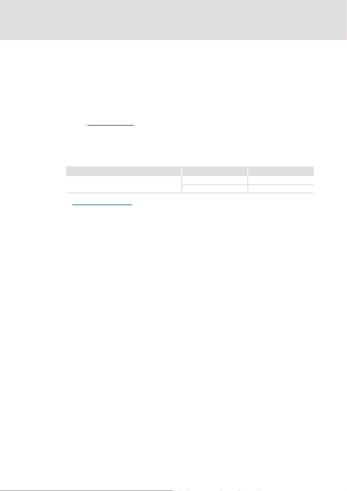
The information given in this documentation is valid for the following devices:
Product series Type designation Device variant
Inverter Drives 8400 motec
Communication unit PROFIBUS
Features and variants
E84DGFCPxNx PROFIBUS
E84DGFCPxJx PROFIBUS + Safety
( 15)
EDS84DMOTPBUS EN 3.0 - 11/2011 L 7
Page 8

Communication manual 8400 motec PROFIBUS
About this documentation
Document history
1.1 Document history
Version Description
1.0 09/2010 TD17 First edition
2.0 01/2011 TD17 • DIP switch settings
• »Engineer« screenshots updated.
3.0 11/2011 TD17 • General revision
• Digital and analog input information
• Description of code C13887
Your opinion is important to us!
These instructions were created to the best of our knowledge and belief to give you the
best possible support for handling our product.
If you have suggestions for improvement, please e-mail us to:
feedback-docu@Lenze.de
( 31) corrected.
( 40) supplemented.
(from version 02.00) supplemented.
Thank you for your support.
Your Lenze documentation team
8 L EDS84DMOTPBUS EN 3.0 - 11/2011
Page 9

1.2 Conventions used
This manual uses the following conventions to distinguish between different types of
information:
Type of information Writing Examples/notes
Numbers
Decimal Standard notation Example: 1234
Hexadecimal 0x[0 ... 9, A ... F] Example: 0x60F4
Binary
• Nibble
Decimal separator Point The decimal point is always used.
Text
Program name » « PC software
Control element Bold The OK button... / The Copy command... / The
Hyperlink Underlined
Symbols
Page reference ( 9) Optically highlighted reference to another page. Can
Step-by-step instructions
Communication manual 8400 motec PROFIBUS
About this documentation
Conventions used
In inverted commas
Point
Example: ’100’
Example: ’0110.0100’
Example: 1234.56
Example: Lenze »Engineer«
Properties tab... / The Name input field...
Optically highlighted reference to another topic. Can
be activated with a mouse-click in this
documentation.
be activated with a mouse-click in this
documentation.
Step-by-step instructions are indicated by a
pictograph.
EDS84DMOTPBUS EN 3.0 - 11/2011 L 9
Page 10

Communication manual 8400 motec PROFIBUS
About this documentation
Terminology used
1.3 Terminology used
Term Meaning
Controller Lenze frequency inverter of the "Inverter Drives 8400 motec" product series
Standard device
The controller 8400 motec consists of the following modules: "Drive unit",
"communication unit" and "wiring unit".
• The drive unit is available in various power classes.
• The communication unit is available in the following versions:
–No fieldbus
–AS-i option
–CANopen option
–PROFIBUS option
–PROFINET option
–EtherCAT option
• The wiring unit provides flexible connection options for an easy integration
into the power supply of the machine.
(parameterisation, diagnostics, and configuration) throughout the entire life
cycle, i.e. from planning to maintenance of the machine commissioned.
common parlance, this term is also referred to as an "index".
"subcodes".
In this documentation a slash "/" is used as a separator between code and
subcode (e.g. "C00118/3").
In common parlance, this term is also referred to as a "subindex".
Drive unit
Communication unit
Wiring unit
»Engineer« Lenze PC software supporting you during the "Engineering" process
Code Parameter by means of which you can parameterise or monitor the controller. In
Subcode If a code contains more than one parameter, these parameters are stored in
Lenze setting These are settings the device is preconfigured with ex works.
Basic setting
HW Hardware
SW Software
10 L EDS84DMOTPBUS EN 3.0 - 11/2011
Page 11

1.4 Notes used
The following signal words and symbols are used in this documentation to indicate
dangers and important information:
Safety instructions
Structure of the safety instructions:
Pictograph and signal word!
(characterise the type and severity of danger)
Note
(describes the danger and informs how to prevent dangerous situations)
Pictograph Signal word Meaning
Communication manual 8400 motec PROFIBUS
About this documentation
Danger! Danger of personal injury through dangerous electrical voltage
Reference to an imminent danger that may result in death or serious
personal injury if the corresponding measures are not taken.
Danger! Danger of personal injury through a general source of danger
Reference to an imminent danger that may result in death or serious
personal injury if the corresponding measures are not taken.
Stop! Danger of property damage
Reference to a possible danger that may result in property damage if the
corresponding measures are not taken.
Notes used
Application notes
Pictograph Signal word Meaning
Note! Important note to ensure trouble-free operation
Tip! Useful tip for easy handling
Reference to other documents
EDS84DMOTPBUS EN 3.0 - 11/2011 L 11
Page 12

Communication manual 8400 motec PROFIBUS
Safety instructions
General safety and application instructions
2 Safety instructions
Note!
Always observe the specified safety measures to avoid severe injury to persons
and damage to property!
Always keep this documentation to hand in the vicinity of the product during
operation.
2.1 General safety and application instructions
Danger!
If you disregard the following basic safety measures, this can cause severe injury
to persons and damage to material assets.
Lenze drive and automation components ...
– must only be used as directed.
Application as directed
– must never be commissioned in the event of visible damage.
– must never be technically modified.
– must never be commissioned before they have been completely mounted.
– must never be operated without the covers required.
– can - depending on their degree of protection - have live, movable or rotating parts
during and after operation. Surfaces can be hot.
For Lenze drive components ...
– use only the accessories approved.
– use only original spare parts from the manufacturer.
Observe all specifications given in the attached and associated documentation.
– This is the precondition for safe and trouble-free operation and for achieving the
product features specified.
Features and variants
– The procedural notes and circuit details described in this document are only
proposals. It is up to the user to check whether they can be adapted to the particular
applications. Lenze does not take any responsibility for the suitability of the
procedures and circuit proposals described.
( 14)
( 15)
12 L EDS84DMOTPBUS EN 3.0 - 11/2011
Page 13

Communication manual 8400 motec PROFIBUS
Device- and application-specific safety instructions
Only qualified personnel may work with and on Lenze drive and automation
components. According to IEC 60364 and CENELEC HD 384, these are persons ...
– who are familiar with the installation, assembly, commissioning and operation of
the product.
– who have the corresponding qualifications for their work.
– who know all regulations for the prevention of accidents, directives and laws
applicable on site and are able to apply them.
2.2 Device- and application-specific safety instructions
During operation, the communication unit must be connected to the wiring unit and
the drive unit.
With external voltage supply, always use a separate power supply unit, safely
separated to EN 61800-5-1 in every control cabinet ("SELV" / "PELV").
Only use cables that correspond to the given specifications.
Bus cable specification
( 25)
Safety instructions
Documentation for "Inverter Drives 8400 motec", control system, system/
machine
All other measures prescribed in this documentation must also be implemented.
Observe the safety instructions and application notes specified in the
documentation.
2.3 Residual hazards
Device protection
The communication unit contains electronic components that can be damaged or
destroyed by electrostatic discharge.
Installation
( 20)
EDS84DMOTPBUS EN 3.0 - 11/2011 L 13
Page 14

Communication manual 8400 motec PROFIBUS
Product description
Application as directed
3 Product description
3.1 Application as directed
The communication unit PROFIBUS ...
is a unit that can only be used in conjunction with the following modules:
Product series Type designation
Inverter Drives 8400 motec
Drive unit
Inverter Drives 8400 motec
Wiring unit
is a device intended for use in industrial power systems.
may only be operated under the operating conditions specified in this documentation.
E84DGDVxxxxxxxx
E84DGVNxx
may only be used in PROFIBUS networks.
can also be used without being connected to the PROFIBUS network.
Any other use shall be deemed inappropriate!
14 L EDS84DMOTPBUS EN 3.0 - 11/2011
Page 15

3.2 Features and variants
The communication unit PROFIBUS is available in the following versions:
Product series Type designation Features
Inverter Drives 8400 motec
Communication unit PROFIBUS
The PROFIBUS communication unit is ...
– mounted on the wiring unit (E84DGVNxx);
– supplied internally via the drive unit (E84DGDVxxxxxxxx) or externally via a
separate voltage source.
Communication manual 8400 motec PROFIBUS
Product description
Features and variants
Enclosure
IP 65
PROFIBUS
M12
I/O: Terminal
E84DGFCPANP zzz
E84DGFCP9NP zz z
E84DGFCPAJP zzz z
E84DGFCP9JP zz zz
I/O: M12
Safety
The I/O connections can be brought into the device via M12 connectors or cable glands.
Devices without integrated safety system (safety option) have no analog input and no
relay output.
The integrated safety system of the E84DGFCPxJx communication units can be used on
machines for the protection of persons.
Support of the parameter data channel DRIVECOM (DP-V0), PROFIDrive (DP-V1) in
preparation
Exchange of up to 8 process data words per direction
Bus coupling via remote bus according to the RS485 standard
Automatic detection of the baud rate (9.6 kbps to 12 Mbps)
Setting of the station address is possible via DIP switch or code.
Communication with the Lenze »Engineer« (access to all Lenze parameters) is executed
via the diagnostic interface of the drive unit.
Hardware manual "Inverter Drives 8400 motec"
Here you will find detailed information on the integrated safety system (safety
option).
Software manual / »Engineer« online help "Inverter Drives 8400 motec"
Here you will find detailed information on how to configure the safety system
(safety option).
EDS84DMOTPBUS EN 3.0 - 11/2011 L 15
Page 16
Communication manual 8400 motec PROFIBUS
Product description
Connections and interfaces
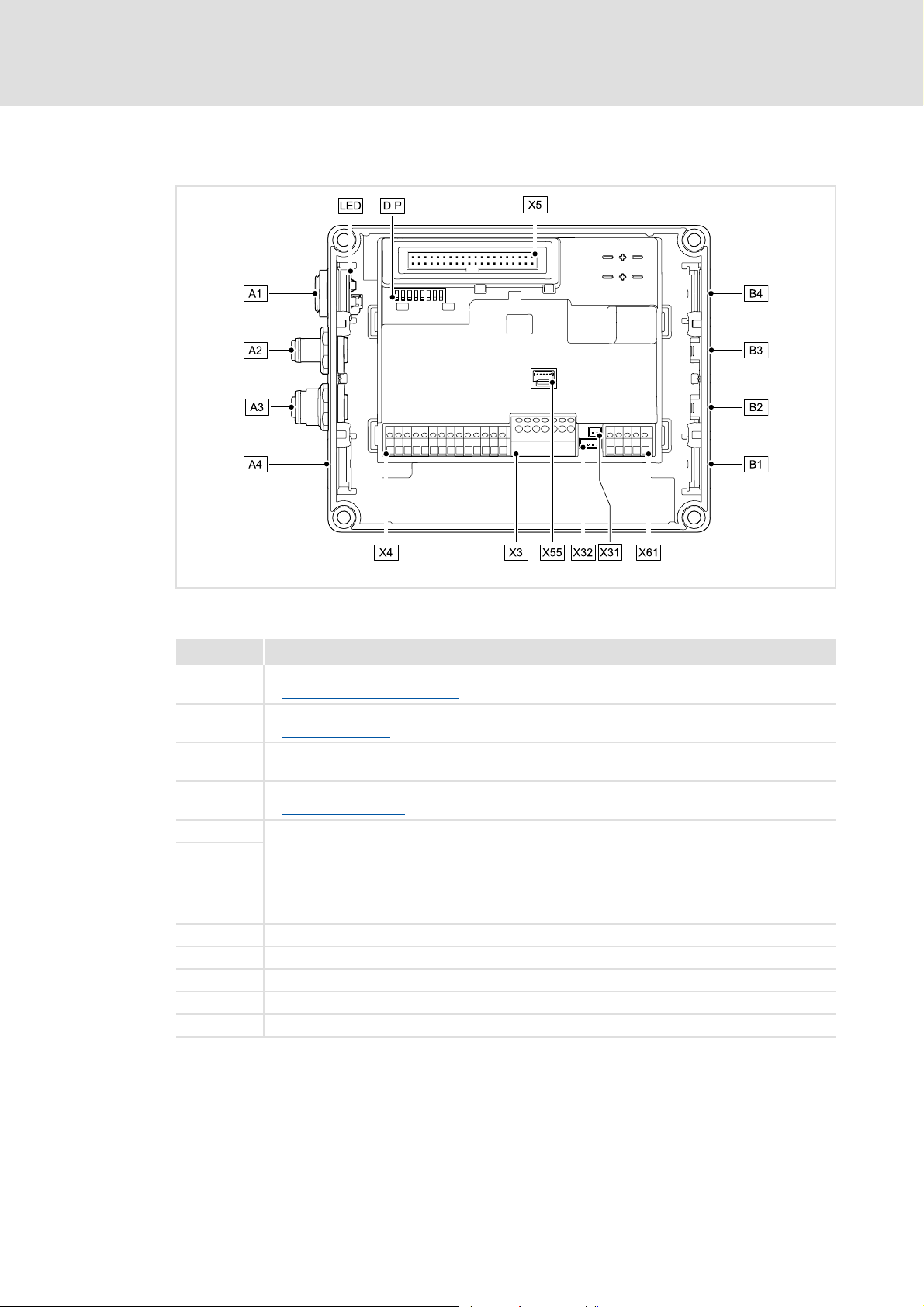
3.3 Connections and interfaces
[3-1] Communication unit PROFIBUS
Pos. Description
DIP DIP switch
Possible settings via DIP switch
A1 / LED Position of LEDs for PROFIBUS status display
LED status displays
A2 PROFIBUS input (M12 male, 5-pin)
PROFIBUS connection
A3 PROFIBUS output (M12 female, 5-pin)
PROFIBUS connection
A4 Positions for more freely designable inputs and outputs:
B1 ... B4
X3 / X4 / X61 Terminal strips for wiring the connections at A4 and B1 ... B4
X5 Plug connector for connection to the drive unit
X31 Plug connector for wiring the PROFIBUS input at A2
X32 Plug connector for wiring the PROFIBUS output at A3
X55 Plug connector for wiring the LEDs at A1
• Digital inputs
•Digital output
• Analog input (only for E84DGFCPxJx)
• Relay output (only for E84DGFCPxJx)
• Connection of safety system "Safety Option" (only for E84DGFCPxJx)
E84DG029
( 30)
( 72)
( 26)
( 26)
16 L EDS84DMOTPBUS EN 3.0 - 11/2011
Page 17

Communication manual 8400 motec PROFIBUS
Product description
Connections and interfaces
On delivery, the PROFIBUS connections and the LEDs for the PROFIBUS status displays
are already mounted and wired:
– PROFIBUS input to plug connector X31
– PROFIBUS output to plug connector X32
– LEDs to plug connector X55
It is also possible to connect the PROFIBUS and other inputs and outputs (e.g. digital
inputs) via the positions A1 ... A4 and B1 ... B4.
For the connections, 5-pin M12 connectors or - alternatively - cable glands (cable cross-
section max. 1.0 mm
The M12 connectors, cable glands and prefabricated system cables can be obtained
from diverse manufacturers.
Wire the M12 connectors or cable glands used to the corresponding contacts of the
terminal strips/plug connectors X3, X4 and X61.
2
, AWG 18) can be used.
Hardware manual "Inverter Drives 8400 motec"
Observe the notes and wiring instructions given in the documentation.
EDS84DMOTPBUS EN 3.0 - 11/2011 L 17
Page 18

Communication manual 8400 motec PROFIBUS
Technical data
General data and operating conditions
4 Technical data
Hardware manual "Inverter Drives 8400 motec"
Here you will find the ambient conditions and information on the
electromagnetic compatibility (EMC) that also apply to the communication unit.
4.1 General data and operating conditions
Area Values
Order designation • E84DGFCPxNx (PROFIBUS)
• E84DGFCPxJx (PROFIBUS + Safety)
Communication profile • PROFIBUS DP-V0 (DRIVECOM)
• PROFIBUS DP-V1 (PROFIdrive), from SW version 2.0
Standards / specifications • IEC 61158 / EN 50170
• IEC 61784
Communication medium RS485
Interface for communication • PROFIBUS input: M12 pins, 5-pole, B-coded
• PROFIBUS output: M12 socket, 5-pole, B-coded
Max. cable length 1200 m (depending on the selected baud rate, the used cable type and
Bus termination Bus terminating resistors are required at the first and last PROFIBUS node
Network topology • Line (without repeater)
Type of station PROFIBUS slave
Number of slave stations • Max. 31 (without repeater)
PNO identification number 0x0A89
Baud rate for cable type A (EN 50170) 9.6 kbps ... 12 Mbps (automatic detection)
External voltage supply • U = 24 V DC (20 V - 0 % ... 29 V + 0 %)
Conformities, approvals • CE
hardware (repeaters))
(implemented in the connector of the bus cable)
• Tree/line (with repeater)
• Max. 125 (with repeater)
•I
= 400 mA
max
•UR / cUR
18 L EDS84DMOTPBUS EN 3.0 - 11/2011
Page 19

4.2 Protocol data
Area Values
Process data words (PCD) 1 ... 8 words (16 bits/word)
Cyclic parameter data channel (DPV0)
Acyclic parameter data channel (DPV1)
PROFIBUS user data length 1 ... 8 words process data channel + 4 words parameter data channel
4.3 Communication time
The communication time is the time between the start of a request and the arrival of the
corresponding response.
The communication times in a PROFIBUS network depend on ...
Communication manual 8400 motec PROFIBUS
Technical data
Protocol data
4 words
Max. 240 bytes
the processing time in the controller;
the transmission delay time (baud rate / telegram length);
the nesting depth of the network.
Processing time in the controller
Data Processing time
Process data Approx. 2 ms
+ 0 ... 1 ms
+ 1 ... x ms
Parameter data Approx. 30 ms + 20 ms tolerance (typical)
• For some codes, the processing time may be longer (see software
manual/»Engineer« online help "Inverter Drives 8400 motec").
update cycle
processing time in the module
application task runtime of the technology application used
(tolerance)
There are no interdependencies between parameter data and process data.
EDS84DMOTPBUS EN 3.0 - 11/2011 L 19
Page 20

Communication manual 8400 motec PROFIBUS
Installation
5 Installation
Stop!
Electrostatic discharge
Electronic components within the communication unit can be damaged or
destroyed by electrostatic discharge.
Possible consequences:
• The communication unit is defective.
• Communication via the fieldbus is not possible or faulty.
• I/O signals are faulty.
• The safety function is faulty.
Protective measures
• Discharge electrostatic charges before touching the communication unit.
20 L EDS84DMOTPBUS EN 3.0 - 11/2011
Page 21
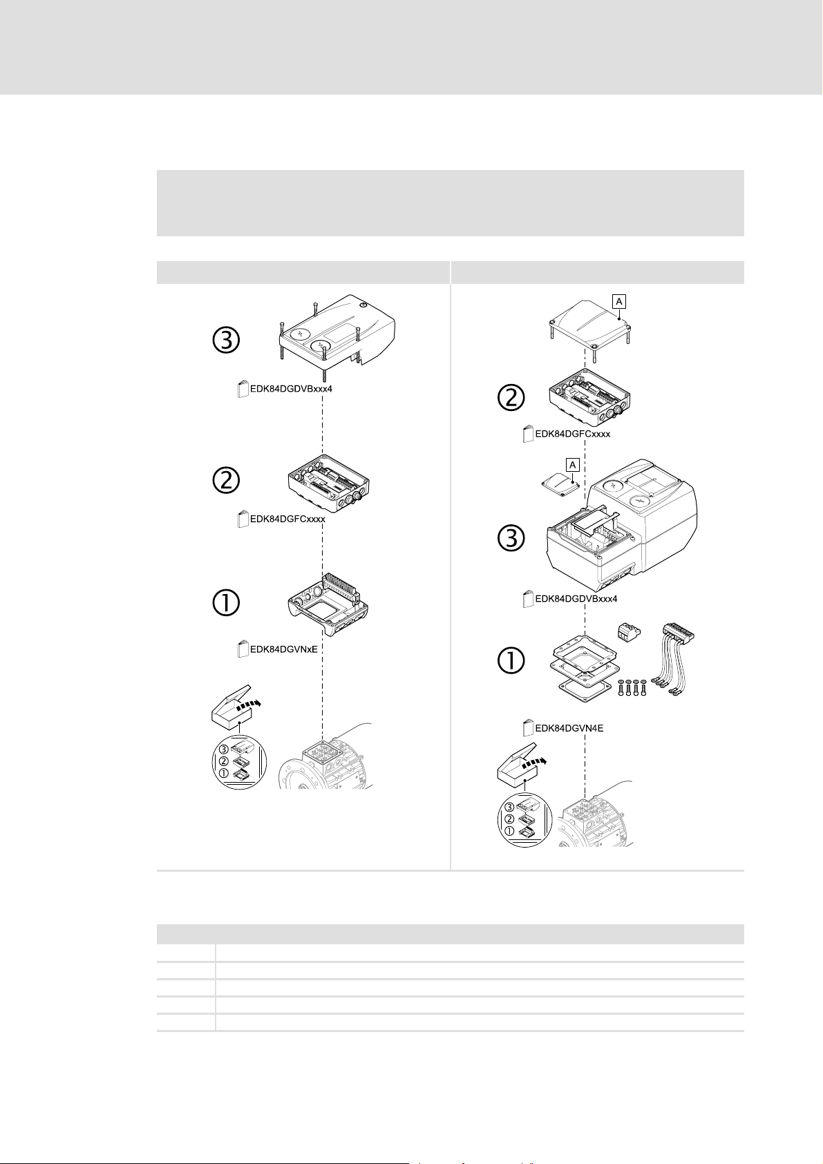
5.1 Mechanical installation
"Inverter Drives 8400 motec" mounting instructions
Here you will find detailed information on the installation.
0.37 ... 3.0 kW 4.0 ... 7.5 kW
Communication manual 8400 motec PROFIBUS
Installation
Mechanical installation
[5-1] Mechanical installation of the 8400 motec components
Legend for fig. [5-1]
1 Drive unit
2 Communication unit
3 Wiring unit
A Cover of the drive unit
EDK84DG... Mounting instructions of the drive unit, communication unit, wiring unit
E84DG023a
E84DG023b
EDS84DMOTPBUS EN 3.0 - 11/2011 L 21
Page 22
Communication manual 8400 motec PROFIBUS
Installation
Electrical installation
5.2 Electrical installation
Hardware manual "Inverter Drives 8400 motec"
Here you will find detailed information about ...
• the digital and analog inputs/outputs;
• the relay output;
• the integrated safety system (safety option);
• the wiring of the connections.
Observe the notes and wiring instructions given in the documentation.
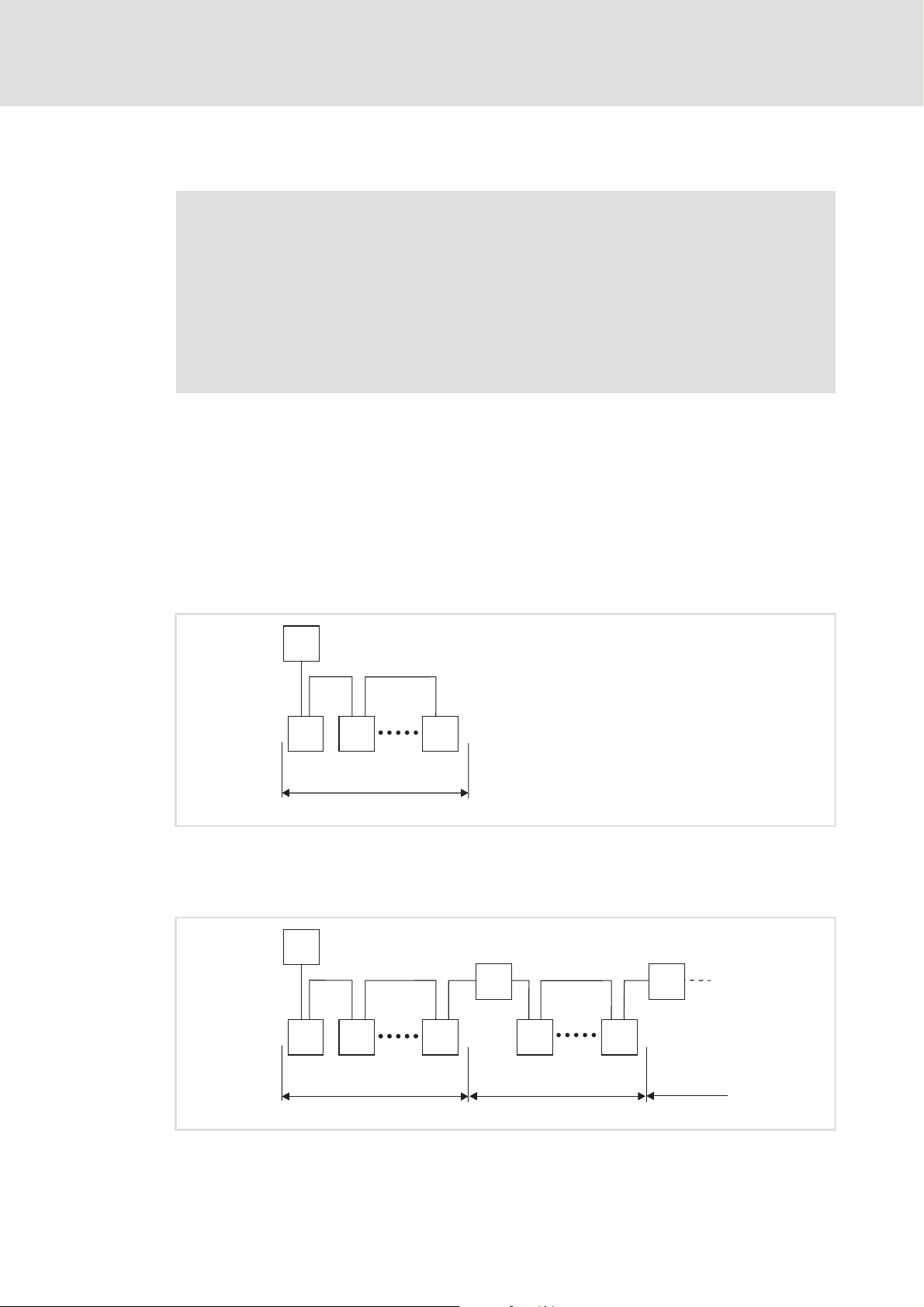
5.2.1 Network topology
The following examples show two simple RS485 networks.
Every segment of the network must be terminated at both ends. The bus terminators of
the PROFIBUS are marked with a "Z" in the below examples.
With a RS485 network of only one segment, the PROFIBUS master (M) with the integrated
bus terminating resistor starts the bus. The bus must be terminated by means of a bus
terminating resistor at the last PROFIBUS station (S).
M
Z
Z
S SS
1
[5-2] RS485 network with one segment
An RS485 network consisting of several segments contains repeaters (R) for connecting the
segments. The repeaters are provided with integrated bus terminating resistors.
M
Z
Z
Z
R
Z
Z
R
Z
E94YCPM012a
S SS
S S
1 23
E94YCPM012b
[5-3] RS485 network with a repeater
22 L EDS84DMOTPBUS EN 3.0 - 11/2011
Page 23
Communication manual 8400 motec PROFIBUS
Installation
Electrical installation
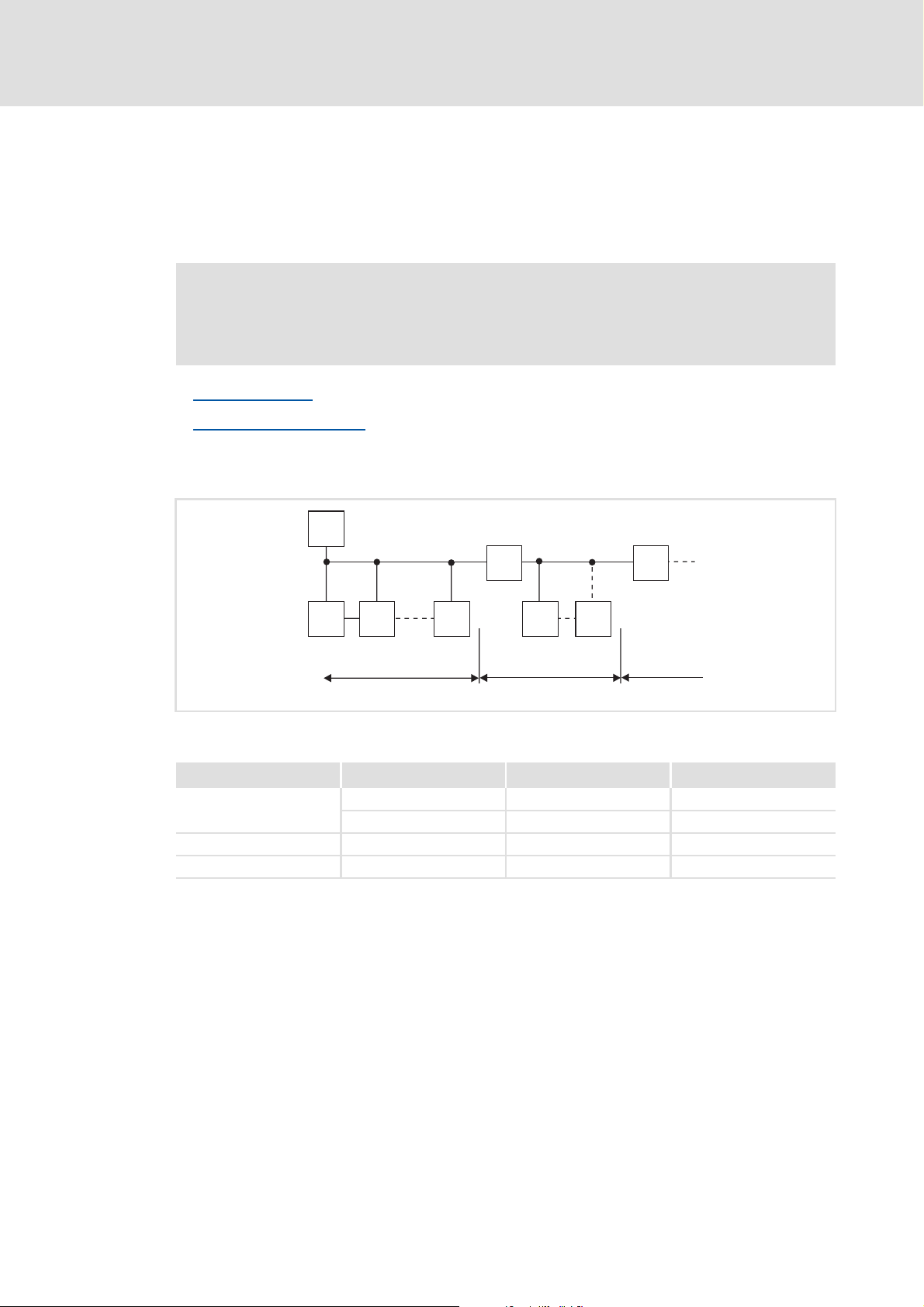
If no repeater is to be used at the end of the segment, the bus must be terminated by
means of a bus terminating resistor at the last station (S). The bus termination is supplied
by this station.
An external supply of the communication unit provides for a supply of the bus termination
independent of the supply of the controller.
Note!
The bus terminator must always be supplied. Otherwise, the bus can get
unstable.
Bus termination
External voltage supply ( 27)
Number of stations
[5-4] Number of stations
Segment Master (M) Slave (S) Repeater (R)
1131-
2-301
3-301
( 24)
M
RR
SS S S S
123
2133PFB004
230-
Tip!
Repeaters do not have a station address. When calculating the maximum number
of stations, they reduce the number of stations by 1 on each side of the segment.
Repeaters can be used to build up line and tree topologies. The maximum total bus
system expansion depends on ...
• the baud rate used;
• the number of repeaters used.
EDS84DMOTPBUS EN 3.0 - 11/2011 L 23
Page 24

Communication manual 8400 motec PROFIBUS
Installation
Electrical installation
5.2.2 Bus termination
The PROFIBUS must be terminated by means of a bus terminating resistor at the first and
last physical station.
In the case of the communication unit, the bus terminating resistor can only be installed
externally at the M12 connector. This has the advantage that an installed resistor is visible
when the device is closed.
Note!
• The PROFIBUS connections (input and output) must be installed in an
enclosed manner. Please use either a connection cable, an enclosed bus
terminator connector (M12 male, 4-pin, B-coded) or a cap.
• Connection cables or bus terminator connectors are offered by several cable
manufacturers (e.g. Lapp or Turck).
• If you want to disconnect individual bus stations, ensure that the bus
terminators at the cable ends remain active. Otherwise, the bus may become
unstable.
• Please observe that the bus termination is not active any longer if ...
– the bus terminator connector has been disconnected;
– the mains supply of the drive unit and the external 24V supply of the
communication unit have been switched off at the same time.
24 L EDS84DMOTPBUS EN 3.0 - 11/2011
Page 25

5.2.3 Bus cable specification
Note!
Only use cables that correspond to the given specifications of the PROFIBUS user
organisation.
Area Values
Cable resistance 135 ... 165 Ω/km, (f = 3 ... 20 MHz)
Capacitance per unit length ≤ 30 nF/km
Loop resistance < 110 Ω/km
Core diameter > 0.64 mm
Core cross-section > 0.34 mm
Cores Twisted in pairs, insulated and shielded
Communication manual 8400 motec PROFIBUS
Installation
Electrical installation
2
Bus cable length
The bus cable length depends on the baud rate used:
Baud rate Length
9.6 ... 93.75 kbps 1200 m
187.5 kbps 1000 m
500 kbps 400 m
1500 kbps 200 m
3000 ... 12000 kbps 100 m
Note!
The baud rate depending of the data volume, cycle time and number of stations
should only be selected as high as required for the application.
Tip!
For high baud rates, we recommend taking the use of optical fibres into
consideration.
Advantages of optical fibres:
• External electromagnetic interferences have no effect on the transmission
path.
• Bus lengths of several kilometres are also possible with higher baud rates.
The bus length is ...
– independent of the baud rate;
– dependent on the optical fibre used.
EDS84DMOTPBUS EN 3.0 - 11/2011 L 25
Page 26
Communication manual 8400 motec PROFIBUS
Installation
Electrical installation
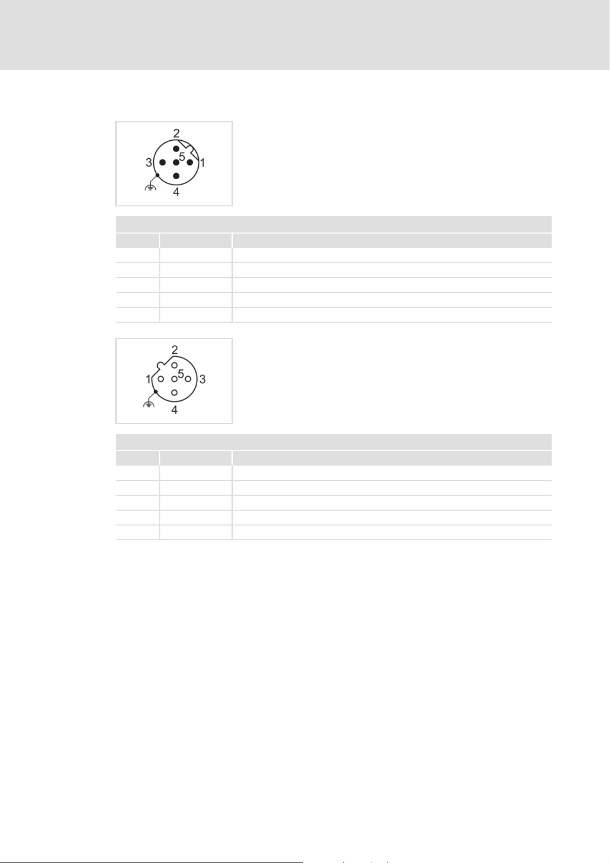
5.2.4 PROFIBUS connection
PROFIBUS input: M12 pins, 5-pole, B-coded
Wiring at terminal strip X31
PROFIBUS input
Pin Signal Description
1 - Not assigned
2 RxD/TxD-N (A) Data line A (received/transmitted data, minus)
3 - Not assigned
4 RxD/TxD-P (B) Data line B (received/transmitted data, plus)
5 - Not assigned
PROFIBUS output: M12 socket, 5-pole, B-coded
Wiring at terminal strip X32
PROFIBUS output
Pin Signal Description
1 P5V2 5 V DC / 30 mA (bus termination)
2 RxD/TxD-N (A) Data line A (received/transmitted data, minus)
3 M5V2 Data ground (ground to 5 V)
4 RxD/TxD-P (B) Data line B (received/transmitted data, plus)
5 - Not assigned (shield connection via housing)
26 L EDS84DMOTPBUS EN 3.0 - 11/2011
Page 27

5.2.5 External voltage supply
By means of the external voltage supply, PROFIBUS communication for commissioning
can be established, and the data of the digital and analog inputs can be queried.
Furthermore the external voltage supply serves to maintain PROFIBUS communication
if the main supply fails.
The digital inputs RFR, DI1 ... DI5 and the analog input can continue to be evaluated.
The external voltage supply is done via the terminals 24E and GND of the terminal strip
X3.
Permissible voltage (DC) / max. current:
– U = 24 V DC (20 V - 0 % ... 29 V + 0 %)
–I
Access to parameters of a device that is disconnected from the mains is not possible.
= 400 mA
max
Communication manual 8400 motec PROFIBUS
Installation
Electrical installation
Hardware manual "Inverter Drives 8400 motec"
Here you can find detailed information on how to wire the communication unit.
EDS84DMOTPBUS EN 3.0 - 11/2011 L 27
Page 28

Communication manual 8400 motec PROFIBUS
Commissioning
Before initial switch-on
6 Commissioning
During commissioning, plant-specific data such as motor parameters, operating
parameters, responses, and parameters for fieldbus communication are defined for the
controller. Lenze devices use codes for this purpose.
The codes of the controller and for communication are saved to the memory module in a
non-volatile data set.
In addition, there are codes for diagnosing and monitoring the stations.
Parameter reference
6.1 Before initial switch-on
Stop!
Before switching on the controller for the first time, check ...
• the entire wiring for completeness, short circuit and earth fault.
• whether the bus system is terminated through a bus terminating resistor at
the first and last physical bus station.
Bus termination
( 81)
( 24)
28 L EDS84DMOTPBUS EN 3.0 - 11/2011
Page 29

6.2 Configuring the host (master)
For communication with the controller, you have to configure the host (master) first.
Configuration for the host (master) and the DP-V0 parameter data channel
For the configuration of the PROFIBUS, the PROFIBUS device description file of the Inverter
Drive 8400 motec must be read into the master.
The device description file is available on Lenze's website in the "Services & Downloads"
area at:
Communication manual 8400 motec PROFIBUS
Commissioning
Configuring the host (master)
www.Lenze.com
The following language variants of the device description file can be used:
LENZE84D.GSD (source file, English)
LENZE84D.GSG (German)
LENZE84D.GSE (English)
Defining the user data length
The user data length is defined during the initialisation phase of the master.
The communication unit PROFIBUS supports the configuration of max. 8 process data
words (max. 16 bytes).
The user data lengths for process input data and process output data are the same.
EDS84DMOTPBUS EN 3.0 - 11/2011 L 29
Page 30
Communication manual 8400 motec PROFIBUS
Commissioning
Possible settings via DIP switch
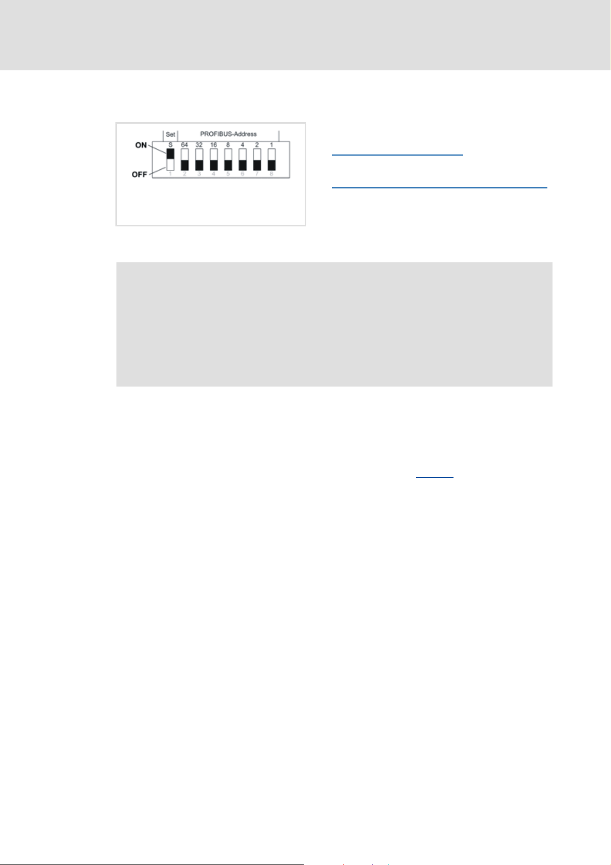
6.3 Possible settings via DIP switch
The DIP switches serve to ...
[6-1] DIP switch
Note!
• The DIP switches can only be accessed when the drive unit is detached from
the communication unit. Loosen the four fixing screws at the drive unit.
Observe the notes in the mounting instructions.
• Switch off the voltage supply of the controller and the external supply of the
communication unit before starting with the disassembly of the drive unit.
• The DIP switches are only read in when the device is switched on.
6.3.1 Receiving the station address via the master
Set the DIP switch S=OFF, in order to receive the station address automatically via the
master.
Setting the station address
(switches: 1 ... 64)
Receiving the station address via the master
( 30)
(switch: S)
Lenze setting: all switches in OFF position
( 31)
The station address active at the PROFIBUS is displayed in C13864
The settings of the DIP switches 1...64 have no effect.
.
30 L EDS84DMOTPBUS EN 3.0 - 11/2011
Page 31

6.3.2 Setting the station address
If there are several networked PROFIBUS stations, the station addresses must differ from
each other.
The station address can be set via the DIP switches 1 ... 64 or via the »Engineer« with code
C13899
.
Communication manual 8400 motec PROFIBUS
Commissioning
Possible settings via DIP switch
If the station address is to be set via C13899
, the DIP switches 1 ... 64 must be set to OFF.
Note!
• The valid address range is 0 ... 126 (max. 125 slaves).
• If all DIP switches 64 ... 1 = ON, the address saved last will be used.
DIP switch settings
DIP switch Station address
S 64 32 16 8 4 2 1
OFF ... ... ... ... ... ... ... Autom. via master
ON OFF OFF OFF OFF OFF OFF OFF Value from C13899
ON OFF OFF OFF OFF OFF OFF ON 1
ON ... ... ... ... ... ... ... ...
ON ON ON ON ON ON ON OFF 126
ON ON ON ON ON ON ON ON Address saved last
The package labelling indicates the valencies of the individual DIP switches for setting the
station address.
Example:
DIP switch 64 32 16 8 4 2 1
Switch position OFF OFF ON OFF ON ON ON
Value 00
Station address = sum of the valencies = 16 + 4 + 2 + 1 = 23
The current address set with the switches is displayed in C13920
The station address active at the PROFIBUS is displayed in C13864
DIP switch positions for setting the station address
16 0 4 2 1
.
.
( 93)
EDS84DMOTPBUS EN 3.0 - 11/2011 L 31
Page 32

Communication manual 8400 motec PROFIBUS
Commissioning
Possible settings via DIP switch
Setting the station address via the »Engineer«
In the »Engineer«, the station address can be set via the Settings tab.
Impermissible addresses are indicated in red in the Station address input field (code
C13899
Save the changed settings with the device command C00002/11 (save all parameter
sets).
).
32 L EDS84DMOTPBUS EN 3.0 - 11/2011
Page 33

6.4 Initial switch-on
Establishing communication
To establish a communication, the controller must be supplied with mains voltage.
By means of the external voltage supply it is possible to maintain PROFIBUS
communication if the main supply fails.
External voltage supply
All parameters (codes) and DIP switch settings are read in at mains connection.
If an error occurs during this process, the "CE04: MCI communication error" error
message (error no. 01.0127.00002) is output.
The settings of the DIP switches determine whether the station address is selected
automatically by the PROFIBUS master or via code C13899
Possible settings via DIP switch
Communication manual 8400 motec PROFIBUS
Commissioning
Initial switch-on
( 27)
.
( 30)
EDS84DMOTPBUS EN 3.0 - 11/2011 L 33
Page 34

Communication manual 8400 motec PROFIBUS
Data transfer
7 Data transfer
The PROFIBUS master and the controller communicate through the exchange of data
telegrams via PROFIBUS. The user data area of the data telegram contains parameter data
or process data. In the controller, different communication channels are assigned to the
parameter data and process data.
Communication channels
The process data channel transmits process data.
– The process data serve to control the drive controller.
– The host (master) can directly access the process data. In the PLC, for instance, the
data are directly assigned to the I/O area.
– Process data are not saved in the controller.
– Process data are transferred cyclically between the host (master) and the controllers
(slaves) (permanent exchange of current input / output data).
– Process data are, for instance, setpoints, actual values, control words and status
words.
– The Inverter Drive 8400 motec can exchange a maximum of 8 process data words
(16 bits/word) per direction.
– In addition to the process data, digital and analog input information can also be
queried. These signals are set permanently to 2 additional data words which must be
parameterised correspondingly in the HW manager.
Digital and analog input information
( 40)
Note!
Observe the direction of the information flow!
• Process input data (Rx data):
– Process data from the controller (slave) to the master
• Process output data (Tx data):
– Process data from the master to the controller (slave)
The parameter data channel serves to transfer parameter data.
– The parameter data channel provides access to all Lenze codes.
– In general, the parameter data transfer is not time-critical.
– Parameter data are, for instance, operating parameters, motor data and diagnostic
information.
– Parameter changes must be stored via code C00002 of the Inverter Drive 8400
motec.
34 L EDS84DMOTPBUS EN 3.0 - 11/2011
Page 35

Communication manual 8400 motec PROFIBUS
8 Process data transfer
8.1 Access to process data / PDO mapping
Process data are transferred via the MCI/CAN interface.
Max. 8 words (16 bits/word) per direction can be exchanged.
The process data are accessed via the port blocks LP_Network_In and
LP_Network_Out. These port blocks are also called process data channels.
The port/function block interconnection of the process data objects (PDO) takes place
via the Lenze »Engineer«.
Process data transfer
Access to process data / PDO mapping
[8-1] External and internal data transfer between bus system, controller, and application
Software manual / »Engineer« online help "Inverter Drives 8400 motec"
Here you will find detailed information on port blocks and port/function block
interconnection in the »Engineer«.
EDS84DMOTPBUS EN 3.0 - 11/2011 L 35
Page 36

Communication manual 8400 motec PROFIBUS
Process data transfer
Port interconnection of the process data objects (PDO)
8.2 Port interconnection of the process data objects (PDO)
Note!
The »Engineer« screenshots shown on the following pages are only examples for
the setting sequence and the resulting screens.
Depending on the software version of the controller and on the version of the
»Engineer« software installed, the screenshots may vary from your »Engineer«
depiction.
The preconfigured port interconnection of the process data objects is activated by setting
code C00007 = 40: Network (MCI/CAN).
How to freely configure the port interconnection in the »Engineer«:
1. Go to Process data objects tab and click Go to application.
2. The Ports tab displays the port blocks MCI_IN and MCI_OUT.
36 L EDS84DMOTPBUS EN 3.0 - 11/2011
Page 37

Communication manual 8400 motec PROFIBUS
Process data transfer
Port interconnection of the process data objects (PDO)
3. Click the port to be configured and press the Change Variable... button.
EDS84DMOTPBUS EN 3.0 - 11/2011 L 37
Page 38

Communication manual 8400 motec PROFIBUS
Process data transfer
Port interconnection of the process data objects (PDO)
4. Via the button, you can assign signals to the process data words in the
Assignment Signal --> Function Block dialog box.
Select the signals and then confirm the selection with the OK button.
38 L EDS84DMOTPBUS EN 3.0 - 11/2011
Page 39

Communication manual 8400 motec PROFIBUS
Process data transfer
Port interconnection of the process data objects (PDO)
For some process data words, you can also assign signals to the individual bits via
the and buttons.
Select the signals and then confirm the selection with OK.
The current interconnection is only displayed if the following control mode has
been set in code C00007 = 40: Network (MCI/CAN).
EDS84DMOTPBUS EN 3.0 - 11/2011 L 39
Page 40

Communication manual 8400 motec PROFIBUS
Process data transfer
Digital and analog input information
8.3 Digital and analog input information
In addition to the process data, digital and analog input information can also be queried.
The signals are set permanently to 2 additional data words which must be parameterised
correspondingly in the HW manager.
Word Bit Function Values / states
1 0 Analog input value (0 ... 10 V) 10 V = 1000
...
9
10 Digital input 3 0: Closed / not active
11 Digital input 4 0: Closed / not active
12 Digital input 5 0: Closed / not active
13 Reserved
14 I/O status 0: I/O data are invalid.
15 Drive status 0: Controller is 'offline'.
2 0 RFR (controller enable) 0: Controller is enabled.
1 Digital input 1 0: Closed / not active
2 Digital input 2 0: Closed / not active
3 Digital input 3 0: Closed / not active
4 Digital input 4 0: Closed / not active
5 Digital input 5 0: Closed / not active
6 Reserved
...
13
14 I/O status 0: I/O data are invalid.
15 Drive status 0: Controller is 'offline'.
(1111101000
dec
1: Open / active
1: Open / active
1: Open / active
1: I/O data are valid.
1: Controller ist 'online'.
1: Controller is not enabled (inhibited).
1: Open / active
1: Open / active
1: Open / active
1: Open / active
1: Open / active
1: I/O data are valid.
1: Controller ist 'online'.
bin
)
40 L EDS84DMOTPBUS EN 3.0 - 11/2011
Page 41

Communication manual 8400 motec PROFIBUS
9 Parameter data transfer
The PROFIBUS communication unit supports the cyclic and acyclic transmission of
parameter data:
Cyclic DP-V0 parameter data are based on the DRIVECOM profile.
If the DP-V0 parameter data channel is active, it additionally occupies 4 words of the
input and output data.
The acyclic DP-V1 parameter data are based on the PROFIdrive profile (PROFIDrive (DP-
V1) in preparation)
9.1 Addressing of the parameter data
The parameter data are addressed via codes which are listed in a code table in this
documentation and in the corresponding documentation of your controller.
Parameter data transfer
Addressing of the parameter data
Parameter reference
Addressing of Lenze parameters
In the case of the DP-V0 parameter data channel, the parameters of a device are not
addressed directly via Lenze code numbers, but via indices (bytes 3 + 4) and subindices
(byte 2).
The conversion is made via an offset (24575 / 0x5FFF):
–PROFIBUS-Index
–PROFIBUS-DP index
Example of C00105 (quick stop deceleration time):
–PROFIBUS-Index
–PROFIBUS-DP index
The parameter values are entered into the user data (bytes 5 to 8) of the telegram.
( 81)
= 24575 - Lenze code numbers
dec
= 0x5FFF - Lenze code number
hex
= 24575 - 105 = 24470
dec
= 0x5FFF - 0x69 = 0x5F96
hex
hex
EDS84DMOTPBUS EN 3.0 - 11/2011 L 41
Page 42

Communication manual 8400 motec PROFIBUS
Parameter data transfer
DRIVECOM parameter data channel (DP-V0)
9.2 DRIVECOM parameter data channel (DP-V0)
The DRIVECOM parameter data channel (DP-V0) ...
enables the parameterisation and diagnostics of the controller.
provides access to all Lenze parameters (codes).
additionally occupies 4 words (16 bits/word) of the input and output data words in the
master.
is identical for both transmission directions.
9.2.1 Telegram structure (overview)
The telegram of the parameter data channel consists of a total of 8 bytes:
Byte 1 Byte 2 Byte 3 Byte 4 Byte 5 Byte 6 Byte 7 Byte 8
Service Subindex Index
High byte
Index
Low byte
Data 4 /
Error 4
Data 3 /
Error 3
Data 2 /
Error 2
Data 1 /
Error 1
The individual bytes are described in detail in the following subchapters.
42 L EDS84DMOTPBUS EN 3.0 - 11/2011
Page 43

9.2.2 Byte 1: Service
Byte 1 Byte 2 Byte 3 Byte 4 Byte 5 Byte 6 Byte 7 Byte 8
Service Subindex Index
Request and response control for the parameter data channel
[9-1] Method of counting for bits 0 ... 7
Bit 0 ... 2: Request
Read/write request from the master to the controller
000 No request
001 Read request
Reading parameter data from the controller
010 Write request (write data to the controller)
Reading parameter data from the controller
100 Data transfer abort by the master
Data transfer abort by the master
Communication manual 8400 motec PROFIBUS
Parameter data transfer
DRIVECOM parameter data channel (DP-V0)
High byte
Index
Low byte
76543210
( 45)
Data 4 /
Error 4
( 44)
( 44)
Data 3 /
Error 3
Data 2 /
Error 2
Data 1 /
Error 1
Bit 3
Reserved
Bit 4/5: Data length
Data length ≤ 4 bytes in the telegram bytes 5 ... 8 (data 1 ... 4 / error 1 ... 4)
00 1 byte
01 2 bytes
10 3 bytes
11 4 bytes
Bit 6: Handshake
Indicates a new request.
• The state of this (toggle) bit is changed by the master for every new request.
• The controller copies the bit into its response telegram.
Bit 7: Status
Status information from the controller to the master when sending the request confirmation.
• This status bit informs the master whether the request has been carried out without errors.
0 Request completed without errors.
1 Request not completed because of an error.
• The status bit set indicates that the telegram is an "error telegram". The data of bytes 5 ... 8 (data/
error) must be interpreted as an error message.
Error codes
( 48)
EDS84DMOTPBUS EN 3.0 - 11/2011 L 43
Page 44

Communication manual 8400 motec PROFIBUS
Parameter data transfer
DRIVECOM parameter data channel (DP-V0)
9.2.2.1 Reading parameter data from the controller
General procedure:
1. Define the user data area of the controller, i.e. define the location of the DP user data
in the host (observe manufacturer-specific information).
2. Enter the address of the required parameter in the "Index" and "Subindex" fields (DP
output data).
3. Request in the service byte = read request.
– The handshake bit in the service byte must be changed (DP output data).
4. Check whether the handshake bit in the service byte is the same for the DP input data
and the DP output data.
– If the handshake bit is the same, the response has been received.
– It is useful to implement a time monitoring tool.
5. Check whether the status bit in the service byte is set:
– Status bit isnot
(data) ( 47).
– Status bit is set: The read request has not
field contains the Error codes
set: The "Data/Error" field contains the required Parameter value
( 48).
been executed correctly. The "Data/Error"
9.2.2.2 Writing parameter data to the controller
General procedure:
1. Define the user data area of the controller, i.e. define the location of the DP user data
in the host (observe manufacturer-specific information).
2. Enter the address of the required parameter in the "Index" and "Subindex" fields (DP
output data).
3. Enter the parameter value in the "Data/Error" field.
4. Request in the service byte = write request.
– The handshake bit in the service byte must be changed (DP output data).
5. Check whether the handshake bit in the service byte is the same for the DP input data
and the DP output data.
– If the handshake bit is the same, the response has been received.
– It is useful to implement a time monitoring tool.
6. Check whether the status bit in the service byte is set:
– Status bit is not
– Status bit is set: The write request has not
field contains the Error codes
set: The write request has been executed correctly.
been executed correctly. The "Data/Error"
( 48).
44 L EDS84DMOTPBUS EN 3.0 - 11/2011
Page 45

Communication manual 8400 motec PROFIBUS
9.2.2.3 Abort of data transfer by the controller
To abort the transfer, the error telegram is used.
The error telegram is marked by a set status bit in the service byte.
The telegram can either be the response to an "Initiate Read/Write Service" or to a
"Read/Write Segment Service".
Controller response in the event of an error:
Byte 1 Byte 2 Byte 3 Byte 4 Byte 5 Byte 6 Byte 7 Byte 8
Service Subindex Index
1t110000 SIDX IDXH IDXL Error Class Error code Additional
9.2.2.4 Data transfer abort by the master
High byte
Low byte
Index
Parameter data transfer
DRIVECOM parameter data channel (DP-V0)
Data 4 /
Error 4
Data 3 /
Error 3
Data 2 /
Error 2
Code High
Data 1 /
Error 1
Additional
Code Low
The master can use this error telegram to abort a running segment transmission.
The error telegram is marked by a set status bit in the service byte.
The service byte also contains the request code "4" (100
bin
).
Bit 4 and bit 5 in the service byte (data length) are without meaning.
Additional information (subindex, index, error information) is not transmitted.
Byte 1 Byte 2 Byte 3 Byte 4 Byte 5 Byte 6 Byte 7 Byte 8
Service Reserved Reserved Reserved Reserved Reserved Reserved Reserved
1txx0100 0 0 0 0000
Controller response in the case of correct execution:
The controller confirms the error telegram of the master by also sending an error telegram.
The error telegram is marked by a set status bit in the service byte.
In the case of correct execution, the telegram contains the error information
"0x00000000" in bytes 5 ... 8.
Additional information (subindex, index) is not transmitted.
Byte 1 Byte 2 Byte 3 Byte 4 Byte 5 Byte 6 Byte 7 Byte 8
Service SIDX IDXH IDXL Error Class Error code Additional
1t110000 0 0 0 0000
Code High
Additional
Code Low
EDS84DMOTPBUS EN 3.0 - 11/2011 L 45
Page 46

Communication manual 8400 motec PROFIBUS
Parameter data transfer
DRIVECOM parameter data channel (DP-V0)
9.2.3 Byte 2: Subindex
Byte 1 Byte 2 Byte 3 Byte 4 Byte 5 Byte 6 Byte 7 Byte 8
Service Subindex Index
High byte
Additional addressing via the subindex is required for those codes of the Inverter Drives
8400 motec that contain subcodes (see code table).
9.2.4 Bytes 3 + 4: Index
Byte 1 Byte 2 Byte 3 Byte 4 Byte 5 Byte 6 Byte 7 Byte 8
Service Subindex Index
High byte
The parameter (Lenze code) is selected via these two bytes according to the formula:
Index
Low byte
Index
Low byte
Data 4 /
Error 4
Data 4 /
Error 4
Data 3 /
Error 3
Data 3 /
Error 3
Data 2 /
Error 2
Data 2 /
Error 2
Data 1 /
Error 1
Data 1 /
Error 1
Index = 24575 - Lenze code number
(See also "Addressing of Lenze parameters
" ( 41))
Example:
The parameter C00105 (quick stop (QSP) deceleration time) is to be addressed:
Index = 24575 - 105 = 24470 = 0x5F96
The entries in bytes 3 + 4 for this example would be:
Byte 1 Byte 2 Byte 3 Byte 4 Byte 5 Byte 6 Byte 7 Byte 8
Service Subindex 0x5F 0x96 Data 4 /
Error 4
Data 3 /
Error 3
Data 2 /
Error 2
Data 1 /
Error 1
46 L EDS84DMOTPBUS EN 3.0 - 11/2011
Page 47

Communication manual 8400 motec PROFIBUS
DRIVECOM parameter data channel (DP-V0)
9.2.5 Bytes 5 ... 8: Parameter value / error information
Byte 1 Byte 2 Byte 3 Byte 4 Byte 5 Byte 6 Byte 7 Byte 8
Service Subindex Index
High byte
The state of the status bit 7 in the service byte determines the meaning of this data field:
Status bit Meaning of bytes 5 ... 8
0 Bytes 5 ... 8 contain the parameter value (data 1 ... 4 ).
Parameter value (data)
1 Bytes 5 ... 8 contain an error message (error 1 ... 4) due to an invalid access.
Error codes
( 48)
Parameter value (data)
Index
Low byte
( 47)
Data 4 /
Error 4
Data 3 /
Error 3
Parameter data transfer
Data 2 /
Error 2
Data 1 /
Error 1
Note!
Strings or data blocks cannot be transmitted.
Depending on the data format, the length of the parameter value is between 1 and 4 bytes.
Data are saved in the Motorola format, i.e. first the high byte (high word), then the low
byte (low word):
Byte 5 Byte 6 Byte 7 Byte 8
High byte Low byte High byte Low byte
High word Low word
Double word
Principle for the assignment of bytes 5 ... 8 with parameter values of different lengths:
Byte 5 Byte 6 Byte 7 Byte 8
Parameter value (length 1)
Parameter value (length 2) 00 00
00 00 00
Parameter value (length 4)
EDS84DMOTPBUS EN 3.0 - 11/2011 L 47
Page 48

Communication manual 8400 motec PROFIBUS
Parameter data transfer
DRIVECOM parameter data channel (DP-V0)
9.2.6 Error codes
The following error messages may appear:
Byte 8 Byte 7 Byte 6 Byte 5 Meaning
Error 1 Error 2 Error 3 Error 4
0x06 0x03 0x00 0x00 No right to access
0x06 0x05 0x11 Invalid subindex
0x06 0x05 0x12 Data length too large
0x06 0x05 0x13 Data length too small
0x06 0x07 0x00 Object does not exist
0x06 0x08 0x00 Data types do not comply with each other
0x08 0x00 0x00 Request cannot be executed
0x08 0x00 0x20 Request cannot be executed at the moment
0x08 0x00 0x22 Request cannot be executed due to the device status / The
0x08 0x00 0x30 Out of value range
0x08 0x00 0x31 Parameter value too high
0x08 0x00 0x32 Parameter value too low
0x08 0x00 0x80 Hardware error
parameter can only be changed in the case of a controller inhibit
48 L EDS84DMOTPBUS EN 3.0 - 11/2011
Page 49

Communication manual 8400 motec PROFIBUS
DRIVECOM parameter data channel (DP-V0)
9.2.7 Telegram examples
9.2.7.1 Read request: Querying the heatsink temperature
The heatsink temperature of the controller is to be read.
Code to be read: C00061
Heatsink temperature: 43 °C
Byte 1: Service (request)
Parameter data transfer
Request = 0t110001
– Bit 0 ... 2 = 001
bin
for read request
bin
– Bit 3 = 0 (reserved)
– Bit 4/5 = 01
for 2-byte data length (only relevant for the response telegram)
bin
– Bit 6 = handshake bit (t ≡ status is changed in the response telegram)
– Bit 7 = status bit (only relevant for the response telegram)
Byte 2: Subindex
Subindex = 0 because code C00061 does not contain any subindices.
Bytes 3 + 4: Index
Index = 24575 - code number = 24575 - 61 = 24514 = 0x5FC2
– Byte 3 (high byte) = 0x5F
– Byte 4 (low byte) = 0xC2
Bytes 5 ... 8: Data
The response telegram contains the value of code C00061:
– Data 3 + 4 = 43 [°C] x 1 (internal factor) = 43 = 0x002B
Result:
Request telegram from master to drive:
Byte 1 Byte 2 Byte 3 Byte 4 Byte 5 Byte 6 Byte 7 Byte 8
Service Subindex Index high byte Index low byte Data 4 Data 3 Data 2 Data 1
0x01 0x00 0x5F 0xC2 0x00 0x00 0x00 0x00
0t000001
Waiting for change of handshake bit 6 in service byte 1 of the response.
bin
00000000
bin
01011111
bin
11000010
bin
00000000
bin
00000000
bin
00000000
bin
00000000
bin
Response telegram from drive to master (for correct execution):
Byte 1 Byte 2 Byte 3 Byte 4 Byte 5 Byte 6 Byte 7 Byte 8
Service Subindex Index high byte Index low byte Data 4 Data 3 Data 2 Data 1
0x11 0x00 0x5F 0xC2 0x00 0x2B 0x00 0x00
0t010001
EDS84DMOTPBUS EN 3.0 - 11/2011 L 49
bin
00000000
bin
01011111
bin
11000010
bin
00000000
bin
00101011
bin
00000000
bin
00000000
bin
Page 50

Communication manual 8400 motec PROFIBUS
Parameter data transfer
DRIVECOM parameter data channel (DP-V0)
9.2.7.2 Write request: Setting the deceleration time for quick stop (QSP)
In the controller, the deceleration time for quick stop (QSP) is to be set to 50 ms.
Code to be written: C00105
Byte 1: Service (request)
Request = 0t110010
– Bit 0 ... 2 = 010
bin
for write request
bin
– Bit 3 = 0 (reserved)
– Bit 4/5 = 11
for 4-byte data length
bin
– Bit 6 = handshake bit (t ≡ status is changed in the response telegram)
– Bit 7 = status bit (only relevant for the response telegram)
Byte 2: Subindex
Subindex = 0 because code C00105 does not contain any subindices.
Bytes 3 + 4: Index
Index = 24575 - code number = 24575 - 105 = 24470 = 0x5F96
– Byte 3 (high byte) = 0x5F
– Byte 4 (low byte) = 0x96
Bytes 5 ... 8: Data
The parameter value of 0.05 s to be set is multiplied by the code-specific factor of
"1000" and entered in the user data:
– Data 1 ... 4 = 0.05 [s] x 1000 (internal factor) = 50 = 0x00000032
Result:
Request telegram from master to drive:
Byte 1 Byte 2 Byte 3 Byte 4 Byte 5 Byte 6 Byte 7 Byte 8
Service Subindex Index high byte Index low byte Data 4 Data 3 Data 2 Data 1
0x72 0x00 0x5F 0x96 0x00 0x00 0x00 0x32
0t110010
Waiting for change of handshake bit 6 in service byte 1 of the response
bin
00000000
bin
01011111
bin
10010110
bin
00000000
bin
00000000
bin
00000000
bin
Response telegram from drive to master (for correct execution):
Byte 1 Byte 2 Byte 3 Byte 4 Byte 5 Byte 6 Byte 7 Byte 8
Service Subindex Index high byte Index low byte Data 4 Data 3 Data 2 Data 1
0x40 0x00 0x5F 0x96 0x00 0x00 0x00 0x32
0t000000
bin
00000000
bin
01011111
bin
10010110
bin
00000000
bin
00000000
bin
00000000
bin
00110010
00110010
bin
bin
50 L EDS84DMOTPBUS EN 3.0 - 11/2011
Page 51

Communication manual 8400 motec PROFIBUS
9.3 PROFIdrive parameter data channel (DP-V1)
Data communication with PROFIBUS DP-V0 is characterised by cyclic diagnostics and cyclic
process data and parameter data transfer.
An optional service extension is the acyclic parameter data transfer of PROFIBUS DP-V1 (in
preparation). This service does not impair the functionality of the standard services under
PROFIBUS DP-V0.
PROFIBUS DP-V0 and PROFIBUS DP-V1 can be operated simultaneously in the same
network. This enables the step-by-step expansion or modification of a system.
The services of PROFIBUS DP-V1 can be used by the class 1 master (PLC) and the class 2
master (diagnostics master, etc.).
The integration of the acyclic service into the fixed bus cycle depends on the corresponding
configuration of the class 1 master:
With configuration, a time slot is reserved.
Without configuration the acyclic service is appended when a class 2 master acyclically
accesses a DP-V1 slave.
Parameter data transfer
PROFIdrive parameter data channel (DP-V1)
Features
Parameter number and subindex addresses with a width of 16 bits each.
Several parameter requests can be combined to one request (multi-parameter
request).
There is always only one parameter request in process (no pipelining).
A parameter request/response must fit into a data block (max. 240 bytes). Requests/
responses cannot be split into several data blocks.
No spontaneous messages are transferred.
There are only acyclic parameter requests.
Profile-specific parameters can be read independently of the slave state.
EDS84DMOTPBUS EN 3.0 - 11/2011 L 51
Page 52

Communication manual 8400 motec PROFIBUS
Parameter data transfer
PROFIdrive parameter data channel (DP-V1)
9.3.1 Connection establishment between master and slave
A class 1 master can always be used to request parameters from a slave if the slave is in the
"Data_Exchange" state.
In addition to the class 1 master, a class 2 master can establish a communication
connection to the slave:
DPV1parameter data channel
Slave
[9-2] Data communication via the DP-V1 parameter data channel
Master
class 1
Read
Write
Master
class 2
E94YCPM010
52 L EDS84DMOTPBUS EN 3.0 - 11/2011
Page 53

9.3.2 Acyclic data transfer
Note!
A parameter request refers to one or several parameter(s) (multi-parameter
request).
Communication manual 8400 motec PROFIBUS
Parameter data transfer
PROFIdrive parameter data channel (DP-V1)
Parameter request
[9-3] Transmission directions
Explanation
A "Write.req" is used to pass the data set (DB47) to the slave in the form of a parameter
request.
Master
DP-V1
Write.req
with data (parameter request)
Write.res
without data
Read.req
without data
Read.res (-)
without data
Read.req
without data
Read.res (+)Parameter response
with data (parameter response)
Slave
Parameter request
Parameter response
Parameter
processing
E94YCPM011
With "Write.res" the master receives the confirmation for the receipt of the message.
The master requests the response of the slave with "Read.req".
The slave responds with "Read.res (-)" if processing has not yet been completed.
After parameter processing, the parameter request is completed by transmitting the
parameter response to the master with "Read.res (+)".
EDS84DMOTPBUS EN 3.0 - 11/2011 L 53
Page 54

Communication manual 8400 motec PROFIBUS
Parameter data transfer
PROFIdrive parameter data channel (DP-V1)
9.3.3 Telegram structure
SD LE LEr SD DA SA FCS EDFC DSAP SSAP
[9-4] PROFIBUS data telegram
DU
The data unit (DU) contains the DP-V1 header and the parameter request or the parameter
response.
The following subchapters describe the parameter request and the parameter response in
detail.
Note!
The DP-V1 header consists of:
• Function identification
•Slot number
•Data set
• Length of the user data
Please refer to the corresponding PROFIBUS specification for further information
on the DP-V1 header.
Assignment of the user data depending on the data type
E82ZAFP015
Depending on the data type used, the user data are assigned as follows:
Data type Length User data assignment
Byte 1 Byte 2 Byte 3 Byte 4 Byte ...
String x bytes
U8 1 byte 00
U16 2 bytes
U32 4 bytes
High byte Low byte
High word Low word
High byte Low byte High byte Low byte
54 L EDS84DMOTPBUS EN 3.0 - 11/2011
Page 55

Communication manual 8400 motec PROFIBUS
9.3.3.1 Reading parameter data from the controller
Note!
• When a read request is processed, no parameter value is written to the slave.
• In the case of a multi-parameter read request, the parameter attribute, index,
and subindex are repeated with the number "n" of the parameters requested.
• A read request must not exceed the maximum data length of 240 bytes.
Request header
Byte 1 Byte 2 Byte 3 Byte 4
Request reference Request identification Axis Number of indices
Field Data type Values
Request reference U8 This value is specified by the master
Request identification U8 0x01: Request parameters for reading
Axis U8 0x00 or 0x01
Number of indices U8 0x"n" (n = number of parameters requested)
Parameter data transfer
PROFIdrive parameter data channel (DP-V1)
Parameter attribute
Byte 5 Byte 6
Attribute Number of subindices
Field Data type Values
Attribute U8 0x10: Value
Number of subindices U8 0x00
(For array elements: Enter the number of array elements
required.)
Index and subindex
Byte 7 Byte 8 Byte 9 Byte 10
Index Subindex
High byte Low byte High byte Low byte
Field Data type Values
Index U16 0x0001 ... 0xFFFF (1 ... 65535)
Subindex U16 0x0001 ... 0xFFFF (1 ... 65535)
EDS84DMOTPBUS EN 3.0 - 11/2011 L 55
Page 56

Communication manual 8400 motec PROFIBUS
Parameter data transfer
PROFIdrive parameter data channel (DP-V1)
9.3.3.2 Response to a correctly executed read request
Note!
Responses to a read request do not contain parameter attributes, indices and
subindices.
Response header
Byte 1 Byte 2 Byte 3 Byte 4
Request reference
(mirrored)
Field Data type Values
Request reference U8 Mirrored value of the parameter request
Response identification U8 0x01: Parameter has been read
Axis U8 0x00 or 0x01
Number of indices U8 0x"n" (n = number of parameters requested)
Response identification Axis
Number of indices
(mirrored)
Parameter format
Byte 5 Byte 6
Format Number of values
Field Data type Values
Format U8 0x02: Integer8
0x03: Integer16
0x04: Integer32
0x05: Unsigned8
0x06: Unsigned16
0x07: Unsigned32
0x09: Visible string
0x0A: Octet string
0x40: Zero
0x41: Byte
0x42: Word
0x43: Double word
Number of values U8 0x01 or number of requested subindices/parameters
(with several subindices/parameters only the parameter
value is repeated).
In the case of string codes, the number of characters is
entered here.
56 L EDS84DMOTPBUS EN 3.0 - 11/2011
Page 57

Parameter value
Byte 7 Byte 8 Byte 9 Byte 10
Field Data type Values
Value String Any (length > 4 bytes possible)
9.3.3.3 Response to a read error
Note!
Communication manual 8400 motec PROFIBUS
Parameter data transfer
PROFIdrive parameter data channel (DP-V1)
Value
U8 0x00 .... 0xFF
U16 0x0000 .... 0xFFFF
U32 0x0000 0000 .... 0xFFFF FFFF
In the case of a multi-parameter request, correct and possible faulty messages
are summarised in one telegram. They have the following data contents:
• Correct message:
– Format: data type of the value requested
– Number of values: as described in chapter "Reading parameter data from
the controller" ( 55).
– Parameter value: value requested
• Faulty message
– Format: 0x44
– Number of values: 0x01 or 0x02
– Error code without additional information (for number of values = 0x01) or
– Error code with additional information (for number of values = 0x02)
A faulty access to a parameter "n" is indicated at the nth position in the response
telegram of a multi-parameter request.
Response header
Byte 1 Byte 2 Byte 3 Byte 4
Request reference
(mirrored)
Response identification Axis
(mirrored)
Number of indices
Field Data type Values
Request reference U8 Mirrored value of the parameter request
Response identification U8 0x81: Parameter has not been read
• The data in the bytes 7 + 8 must be interpreted as an
error code.
Axis U8 0x00 or 0x01
Number of indices U8 0x"n" (n = number of parameters requested)
EDS84DMOTPBUS EN 3.0 - 11/2011 L 57
Page 58

Communication manual 8400 motec PROFIBUS
Parameter data transfer
PROFIdrive parameter data channel (DP-V1)
Parameter format
Byte 5 Byte 6
Format Number of values
Field Data type Values
Format U8 0x44: Error
Number of values U8 0x01: Error code without additional information
0x02: Error code with additional information
Error code
Byte 7 Byte 8 Byte 9 Byte 10
Error code Additional information
High byte Low byte High byte Low byte
(if available)
Field Data type Values
Error code U16 0x0000 .... 0xFFFF
Additional information
(if available)
U16
9.3.3.4 Writing parameter data to the controller
Note!
When a multi-parameter write request is transferred, the ...
• Parameter attribute
• Index and subindex
and then the ...
• Parameter format
• Parameter value
... are repeated with the number "n" of the parameters addressed.
A write request must not exceed the maximum data length of 240 bytes.
Error codes
( 63)
58 L EDS84DMOTPBUS EN 3.0 - 11/2011
Page 59

Communication manual 8400 motec PROFIBUS
Parameter data transfer
PROFIdrive parameter data channel (DP-V1)
Request header
Byte 1 Byte 2 Byte 3 Byte 4
Request reference Request identification Axis Number of indices
Field Data type Values
Request reference U8 This value is defined by the master.
Request identification U8 0x02: Write parameter
Axis U8 0x00 or 0x01
Number of indices U8 0x"n" (n = number of parameters addressed)
Parameter attribute
Byte 5 Byte 6
Attribute Number of subindices
Field Data type Values
Attribute U8 0x10: Value
Number of subindices U8 0x00
(For array elements: Enter the number of array elements
required.)
Index and subindex
Byte 7 Byte 8 Byte 9 Byte 10
Index Subindex
High byte Low byte High byte Low byte
Field Data type Values
Index U16 0x0001 ... 0xFFFF (1 ... 65535)
Subindex U16 0x0001 ... 0xFFFF (1 ... 65535)
EDS84DMOTPBUS EN 3.0 - 11/2011 L 59
Page 60

Communication manual 8400 motec PROFIBUS
Parameter data transfer
PROFIdrive parameter data channel (DP-V1)
Parameter format
Byte 11 Byte 12
Format Number of values
Field Data type Values
Format U8 0x02: Integer8
0x03: Integer16
0x04: Integer32
0x05: Unsigned8
0x06: Unsigned16
0x07: Unsigned32
0x09: Visible string
0x0A: Octet string
0x40: Zero
0x41: Byte
0x42: Word
0x43: Double word
Number of values U8 0x01 or number of written subindices/parameters (with
several subindices/parameters only the parameter value
is repeated).
In the case of string codes, the number of characters is
entered here.
Parameter value
Byte 13 Byte 14 Byte 15 Byte 16
Value
Field Data type Values
Value String any (length > 4 bytes possible)
U8 0x00 .... 0xFF
U16 0x0000 .... 0xFFFF
U32 0x0000 0000 .... 0xFFFF FFFF
60 L EDS84DMOTPBUS EN 3.0 - 11/2011
Page 61

Communication manual 8400 motec PROFIBUS
9.3.3.5 Response to a correctly executed write request
Note!
In the case of a multi-parameter request, correct and possible faulty messages
are summarised in one telegram. They have the following data contents:
• Correct message
– Format: 0x40
– Number of values: 0x00
• Faulty message
– Format: 0x44
– Number of values: 0x01 or 0x02
– Error code without additional information (for number of values = 0x01) or
with additional information (for number of values = 0x02)
Parameter data transfer
PROFIdrive parameter data channel (DP-V1)
A faulty access to a parameter "n" is indicated at the nth position in the response
telegram of a multi-parameter request.
Response header
Byte 1 Byte 2 Byte 3 Byte 4
Request reference
(mirrored)
Field Data type Values
Request reference U8 Mirrored value of the parameter request
Response identification U8 0x02: Parameter has been written
Axis U8 0x00 or 0x01
Number of indices U8 0xn (n = number of parameters addressed)
Response identification Axis
(mirrored)
Number of indices
EDS84DMOTPBUS EN 3.0 - 11/2011 L 61
Page 62

Communication manual 8400 motec PROFIBUS
Parameter data transfer
PROFIdrive parameter data channel (DP-V1)
9.3.3.6 Response to a write error
Response header
Byte 1 Byte 2 Byte 3 Byte 4
Request reference
(mirrored)
Field Data type Values
Request reference U8 Mirrored value of the parameter request
Response identification U8 0x82: Parameter has not been written
Axis U8 0x00 or 0x01
Number of indices U8 0x"n" (n = number of parameters addressed)
Parameter format
Response identification Axis
• The data in the bytes 7 + 8 must be interpreted as an
Number of indices
(mirrored)
error code.
Byte 5 Byte 6
Format Number of values
Field Data type Values
Format U8 0x44: Error
Number of values U8 0x01: Error code without additional information
0x02: Error code with additional information
Error code
Byte 7 Byte 8 Byte 9 Byte 10
Error code Additional information
(if available)
High byte Low byte High byte Low byte
Field Data type Values
Error code U16 0x0000 .... 0xFFFF
Additional information
(if available)
U16
Error codes
( 63)
62 L EDS84DMOTPBUS EN 3.0 - 11/2011
Page 63

9.3.4 Error codes
Communication manual 8400 motec PROFIBUS
Parameter data transfer
PROFIdrive parameter data channel (DP-V1)
Error code Description Explanation Additional
0x0000 Impermissible parameter
number
0x0001 Parameter value cannot be
changed
0x0002 Lower or upper value limit
exceeded
0x0003 Faulty subindex Access to unavailable subindex Subindex
0x0004 No array Access with subindex to non-indicated parameter -
0x0005 Wrong data type Change access with value that does not match the
0x0006 No setting permitted (only
resettable)
0x0007 Description element cannot
be changed
0x0008 Reserved (PROFIdrive profile V2: PPO-Write requested in the IR
0x0009 Description data not
available
0x000A Reserved (PROFIdrive profile V2: Wrong access group) -
0x000B No parameter change rights Change access without parameter change rights -
0x000C Reserved (PROFIdrive profile V2: Wrong password) -
0x000D Reserved (PROFIdrive profile V2: Text in the cyclic traffic
0x000E Reserved (PROFIdrive profile V2: Name in the cyclic traffic
0x000F No text array available Access to unavailable text array (parameter value is
0x0010 Reserved (PROFIdrive profile V2: Missing PPO-Write) -
0x0011 Request cannot be executed
due to the operating state
0x0012 Reserved (PROFIdrive profile V2: Other error) -
0x0013 Reserved (PROFIdrive profile V2: date in the cyclic traffic
0x0014 Value impermissible Change access with the value that is inside the value
0x0015 Response too long The length of the current response exceeds the
0x0016 Parameter address
impermissible
0x0017 Format impermissible Write request: Impermissible or non-supported
0x0018 Number of values not
consistent
0x0019 Reserved - -
...
0x0064
Access to unavailable parameter -
Change access to a parameter value that cannot be
changed
Change access with value beyond the value limits Subindex
data type of the parameter
Change access with value unequal to 0 where this is
not permitted
Change access to a description element that cannot
be changed
is not available)
Access to unavailable description (parameter value is
available)
cannot be read)
cannot be read)
available)
Access is not possible due to temporary reasons not
specified here
cannot be read)
limits but not permissible for other permanent
reasons (parameters with defined individual values)
maximum transmittable length
Impermissible or non-supported value for attribute,
number of subindices, parameter number, or
subindex, or a combination
format of parameter data
Write request: Number of values of the parameter
data do not match the number of subindices in the
parameter address
information
Subindex
-
Subindex
Subindex
-
-
-
-
-
-
-
Subindex
-
-
-
-
EDS84DMOTPBUS EN 3.0 - 11/2011 L 63
Page 64

Communication manual 8400 motec PROFIBUS
Parameter data transfer
PROFIdrive parameter data channel (DP-V1)
Error code Description Explanation Additional
0x0065 Manufacturer-specific - -
...
0x00FF
information
64 L EDS84DMOTPBUS EN 3.0 - 11/2011
Page 65

Communication manual 8400 motec PROFIBUS
PROFIdrive parameter data channel (DP-V1)
9.3.5 Telegram examples
9.3.5.1 Read request: Querying the heatsink temperature
The heatsink temperature of the controller is to be read.
Code to be read: C00061
Heatsink temperature: 43 °C
Parameter request
Byte 1 Byte 2 Byte 3 Byte 4
Request reference Request identification Axis Number of indices
0xXX 0x01 0x00 0x01
Request parameters for reading
Parameter data transfer
Byte 5 Byte 6
Attribute Number of subindices
0x10 0x00
Value No subindex
Byte 7 Byte 8 Byte 9 Byte 10
Index Subindex
High byte Low byte High byte Low byte
0x5F 0xC2 0x00 0x00
Index = 24575 - code no. = 24575 - 61 = 24514 = 0x5F C2 No subindex
EDS84DMOTPBUS EN 3.0 - 11/2011 L 65
Page 66

Communication manual 8400 motec PROFIBUS
Parameter data transfer
PROFIdrive parameter data channel (DP-V1)
Parameter response to a correctly executed read request
Byte 1 Byte 2 Byte 3 Byte 4
Request reference Response identification Axis Number of indices
0xXX 0x01 0x00 0x01
(mirrored) Parameter has been read (mirrored)
Byte 5 Byte 6
Format Number of values
0x03 0x01
Integer16 1 value
Byte 7 Byte 8
Value
High byte Low byte
0x00 0x2B
Value read = 0x 00 2B = 43 x 1 (internal factor) = 43 [°C]
Parameter response to a read error
Byte 1 Byte 2 Byte 3 Byte 4
Request reference Response identification Axis Number of indices
0xXX 0x81 0x00 0x01
(mirrored) Parameter has not been read (mirrored)
Byte 5 Byte 6
Format Number of values
0x44 0x01
Error Error code without additional
Byte 7 Byte 8
Error code
High byte Low byte
For the meaning, see the "Error codes" ( 63) chapter
information
66 L EDS84DMOTPBUS EN 3.0 - 11/2011
Page 67

Communication manual 8400 motec PROFIBUS
PROFIdrive parameter data channel (DP-V1)
9.3.5.2 Write request: Setting the deceleration time for quick stop (QSP)
In the controller, the deceleration time for quick stop (QSP) is to be set to 50 ms.
Code to be written: C00105
Parameter request
Byte 1 Byte 2 Byte 3 Byte 4
Request reference Request identification Axis Number of indices
0xXX 0x02 0x00 0x01
Write parameter Axis 0 1 index
Byte 5 Byte 6
Attribute Number of subindices
0x10 0x00
Value No subindex
Parameter data transfer
Byte 7 Byte 8 Byte 9 Byte 10
Index Subindex
High byte Low byte High byte Low byte
0x5F 0x96 0x00 0x00
Index = 24575 - code no. = 24575 - 105 = 24470 = 0x5F 96 No subindex
Byte 11 Byte 12
Format Number of values
0x43 0x01
Double word 1 value
Byte 13 Byte 14 Byte 15 Byte 16
Value
High word: high byte High word: low byte Low- word: high byte Low word: low byte
0x00 0x00 0x00 0x32
Value to be written = 0.05 [s] x 1000 (internal factor) = 50 = 0x00 00 00 32
EDS84DMOTPBUS EN 3.0 - 11/2011 L 67
Page 68

Communication manual 8400 motec PROFIBUS
Parameter data transfer
PROFIdrive parameter data channel (DP-V1)
Parameter response to a correctly executed write request
Byte 1 Byte 2 Byte 3 Byte 4
Request reference Response identification Axis Number of indices
0xXX 0x02 0x00 0x01
(mirrored) Parameter has been written (mirrored) 1 index
Parameter response to a read error
Byte 1 Byte 2 Byte 3 Byte 4
Request reference Response identification Axis Number of indices
0xXX 0x82 0x00 0x01
(mirrored) Parameter has not been written (mirrored) 1 index
Byte 5 Byte 6
Format Number of values
0x44 0x01
Error Error code without additional
information
Byte 7 Byte 8
Error code
High byte Low byte
For the meaning, see the "Error codes" ( 63) chapter
68 L EDS84DMOTPBUS EN 3.0 - 11/2011
Page 69

Communication manual 8400 motec PROFIBUS
Permanent interruption of PROFIBUS communication
10 Monitoring
10.1 Permanent interruption of PROFIBUS communication
If the PROFIBUS communication is interrupted permanently, e.g. by cable breakage or
failure of the PROFIBUS master, no process data are transmitted to the slave being in the
"Data_Exchange" state.
After the watchdog monitoring time determined by the PROFIBUS master has expired, the
response parameterised in C13880/1
is executed.
Monitoring
The process data handling depends on the setting in C13885
master can either be used or set to zero.)
Preconditions for a controller (slave) response
A monitoring time of 1 ... 65534 ms is set for the "Data_Exchange" state (C13881
A value of "65535 ms" (Lenze setting) deactivates the monitoring.
A response is set for the slave in C13880/1
The slave is in the "Data_Exchange" state.
The watchdog monitoring time is configured correctly in the master.
If one of these preconditions is not met, the response to the absence of cyclic process data
telegrams from the master is not executed.
Settings and displays in the »Engineer«
(Lenze setting: "No response").
( 71)
. (The last data sent by the
).
EDS84DMOTPBUS EN 3.0 - 11/2011 L 69
Page 70

Communication manual 8400 motec PROFIBUS
Monitoring
Short-time interruption of PROFIBUS communication
10.2 Short-time interruption of PROFIBUS communication
POWER ON
Set_Slave_Add
Slave_Diag
Chk_Cfg, not o.k.
Set_Prm, not o.k.
[10-1] Sequence for short-time interruption of communication
WAIT_PRM
WAIT_CFG
Chk_Cfg, o.k.
DATA_EXCH
Slave_Diag
Get_Cfg
Slave_Diag
Set_Prm
Get_Cfg
The master detects the communication fault and only after a few microseconds it transfers
the slave to the WAIT_PRM state of the DP state machine (see fig. [10-1]
).
Only after the state chain of the DP state machine ending in the "Data_Exchange" state
(DATA_EXCH) has been passed through, the watchdog monitoring time calculated for the
slave (in milliseconds) continues to run.
Note!
The watchdog monitoring time does not continue to run when the slave does
not reach the "Data_Exchange" state due to repeated communication errors
(e.g. caused by loose contact).
2133PFB006
Additional monitoring for the data exchange
An additional monitoring function for data exchange is available under code C13881
. This
monitoring function already becomes active when the "Data_Exchange" state is exited
and the parameterised time (0 ... 65535 ms) has expired. The monitoring function then
triggers the response parameterised under C13880/1
.
Note!
Observe the following condition for the time setting:
Monitoring time for data exchange (C13881
PROFIBUS (C13882/1
70 L EDS84DMOTPBUS EN 3.0 - 11/2011
).
) ≤ watchdog monitoring time of
Page 71

Communication manual 8400 motec PROFIBUS
10.3 Settings and displays in the »Engineer«
For monitoring the PROFIBUS communication, you can set a Lenze-internal monitoring
time (C13881
Monitoring tab.
The watchdog monitoring time defined in the PROFIBUS master is displayed in code
C13882
.
) and a response of the controller (C13880) in the »Engineer« via the
Monitoring
Settings and displays in the »Engineer«
If the controller does not receive any valid process data when being in the
"Data_Exchange" state, the process data are handled according to the setting in
C13885
Moreover, you can set the error responses in the controller that cause a setting of the
external diagnostic bit ("Diag-Bit") (C13886
. (The last data sent by the master can either be used or set to zero.)
).
EDS84DMOTPBUS EN 3.0 - 11/2011 L 71
Page 72

Communication manual 8400 motec PROFIBUS
Diagnostics
LED status displays
11 Diagnostics
PROFIBUS communication faults can be diagnosed via the LEDs of the communication unit.
Moreover, the »Engineer« provides PROFIBUS diagnostic information.
11.1 LED status displays
E84DG056
LED Colour State Description
MS Green On
The communication module is supplied with voltage and has
established a connection to the standard device.
Blinking
200 ms
200 ms
The communication module is supplied with voltage, but has not yet
established a connection to the standard device. (Standard device is
switched off, initialising or not present.)
ME Red On
An error concerning the communication module has occurred.
BS Green Off The communication module is not active on the fieldbus or is in the
"Init" state.
Blinking
200 ms
200 ms
The communication module is in the "Data_Exchange" state.
BE Red Blinking
200 ms
200 ms
Incorrect setting for the station address.
The communication module is initialised and internally operates
with the respective default values.
On
Bus error/fault is active (e.g. bus cable unplugged).
72 L EDS84DMOTPBUS EN 3.0 - 11/2011
Page 73

Communication manual 8400 motec PROFIBUS
11.2 Diagnostics with the »Engineer«
In the »Engineer« under the Diagnostics tab, various pieces of PROFIBUS diagnostics
information are displayed.
Diagnostics
Diagnostics with the »Engineer«
EDS84DMOTPBUS EN 3.0 - 11/2011 L 73
Page 74

Communication manual 8400 motec PROFIBUS
Diagnostics
Querying the current bus status
11.3 Querying the current bus status
Code C13861
Bit assignment Description
Bit 3 Bit 2 Bit 1 Bit 0 Reserved
displays the current PROFIBUS status is a bit-coded form:
Bit 5 Bit 4 State of the DP state machine (DP-STATE)
0 0 WAIT_PRM The slave waits for a parameter data telegram after
0 1 WAIT_CFG The slave waits for the configuration telegram that specifies
1 0 DATA_EX If the parameter settings and the configuration have been
1 1 Not possible
Bit 7 Bit 6 State of the Watchdog-State-Machine (WD-STATE)
0 0 BAUD_SEARCH The slave is able to recognise the baud rate automatically.
0 1 BAUD_CONTROL After recognising the correct baud rate, the slave status
1 0 DP_CONTROL The DP_CONTROL status serves for response monitoring of
1 1 Not possible
acceleration. Other types of telegrams will not be processed.
Data exchange is not yet possible.
the number of input and output bytes. The master informs
the slave about the number of I/O bytes that will be
transferred.
accepted by the firmware and by the application, the slave
state changes to "Data_Exchange" (exchange of user data
with the master).
changes to BAUD_CONTROL, and the baud rate is monitored.
the master.
Bit 11 Bit 10 Bit 9 Bit 8 Detected PROFIBUS baud rate
000012 Mbps
00016 Mbps
00103 Mbps
00111.5 Mbps
0 1 0 0 500 kbps
0 1 0 1 187.5 kbps
011093.75 kbps
011145.45 kbps
100019.2 kbps
10019.6 kbps
Bit 15 Bit 14 Bit 13 Bit 12 Reserved
74 L EDS84DMOTPBUS EN 3.0 - 11/2011
Page 75

11.4 Diagnostic data
Present diagnostic data are signalled to the master by the PROFIBUS slave via an alarm
message.
Errors and warnings of the controller are sent to the master as extended diagnostic
messages.
General structure of diagnostic messages
Byte Description
1 Bit 0: Station does not exist (set by the master).
Bit 1: Slave is not ready for data exchange.
Bit 2: Configuration data do not correspond.
Bit 3: Slave has extended diagnostic data.
Bit 4: Requested function is not supported by the slave.
Bit 5: Slave response is invalid (set by the master)
Bit 6: Incorrect parameter setting
Bit 7: Slave has been parameterised by another master (set by the master).
2 Bit 0: Slave must be parameterised again.
Bit 1: Static diagnostics
Bit 2: Permanently set to "1".
Bit 3: Watchdog active
Bit 4: Freeze command received.
Bit 5: Sync command received.
Bit 6: Reserved
Bit 7: Slave is deactivated (set by the master).
3 Bit 7: Diagnostics overflow - amount of diagnostic information present in the slave is too large to fit
into one telegram.
4 Bits 0 ... 7: Master address after parameterisation ("0xFF" without parameterisation)
5 Bits 0 ... 7: ID number (high byte)
6 Bits 0 ... 7: ID number (low byte)
7Header
• The header contains the block length of the advanced diagnostics including the header byte.
• In this case, the value of the entry is "0x0A" (bytes 7 ... 16 = 10 bytes).
8 Status_Type
• The value of this entry is fixed. For the following bit assignment it is "0x81":
9Slot_Number
• The value of the slot number is "0x00".
10 Specifier
• An indicated error is entered in the specifier with the identification "0x1" (status coming).
• An eliminated error is entered in the specifier with the identification "0x02" (status going).
• If no errors are indicated, the entry in the specifier has the value "0x00" (no further
11 Reserved
12
13 ... 16 Error code of the controller
Communication manual 8400 motec PROFIBUS
Diagnostics
Diagnostic data
–Bit 7 = 1: "status"
–Bit 0 = 1: "status message"
–Value of all other bits = 0
differentiation).
EDS84DMOTPBUS EN 3.0 - 11/2011 L 75
Page 76

Communication manual 8400 motec PROFIBUS
Diagnostics
Diagnostic data
Error code of the Inverter Drive 8400 motec
If an error occurs in the controller, the logbook saves a 32-bit value in an error format which
consists of the following information:
30
31
Bit
29
[11-1] Structure of the error number
Bytes 13 ... 16 of the diagnostic message contain the error code of the controller.
In the logbook and in code C00165, the error number is shown in the following syntax
in order to facilitate the readability:
[Error type].[Error field no.].[Error ID]
Software manual/»Engineer« online help for Inverter Drives 8400 motec
Here you'll find detailed information on the structure and contents of the error
codes.
Example: Error "Short circuit (OC1)"
Byte Value
[hex]
1 x Standard data (PRM_Fault)
...
6
7 0A Block length of the advanced diagnostics = 10 bytes
8 81 Status message
900Slot 0
10 01 Status coming
11 00
12 00
13 0B Error message 0x11C4000B ("Short circuit (OC1)")
14 00
15 C4
16 11
210 3
162526
Description
• Error type: "Warning locked"
• Subject area: 0x11C4 (current)
• Error ID: 0x000B
Thus, the error number "0x11C4000B" means: An overcurrent has been detected in
the "current" subject area. This overcurrent causes a "Warning locked" error
response which has to be unlocked after the error has been removed.
A Reserved
B Error type
015
C Error subject area
D Error ID
76 L EDS84DMOTPBUS EN 3.0 - 11/2011
Page 77

Communication manual 8400 motec PROFIBUS
Short overview (A-Z) of the PROFIBUS error messages
12 Error messages
This chapter complements the error list in the software manual and the »Engineer« online
help for the Inverter Drive 8400 motec by PROFIBUS error messages.
Software manual/»Engineer« online help for Inverter Drives 8400 motec
Here you can find general information on diagnostics & fault analysis and on
error messages.
12.1 Short overview (A-Z) of the PROFIBUS error messages
The following table contains all PROFIBUS error messages in alphabetical order with the
preset error response as well as – if applicable – the parameter for setting the error
response.
Error messages
Tip!
When you click the cross-reference in the last column, you will see a detailed
description (causes and remedies) of this error message.
Error text Error type Subject area
Error: Lenze settings loaded 1: Fault 444 25632 - 0x01bc6420
Internal error 1: Fault 444 24832 - 0x01bc6100
Internal error 1: Fault 444 24592 - 0x01bc6010
Internal error 1: Fault 444 24833 - 0x01bc6101
Internal error 1: Fault 444 24848 - 0x01bc6110
Restart after watchdog reset 1: Fault 444 24593 - 0x01bc6011
Profibus Watchdog: DP-V1 MSC2 elapsed 1: Fault 444 33074 C13880/2 0x01bc8132
Profibus Watchdog: Monitoring time elapsed 1: Fault 444 33072 C13880/1 0x01bc8130
Profibus: State Data_Exchange left 1: Fault 444 33073 C13880/1 0x01bc8131
Memory. No access 1: Fault 444 21809 - 0x01bc5531
Memory. Read error 1: Fault 444 21810 - 0x01bc5532
Memory. Write error 1: Fault 444 21811 0x01bc5533
Invalid parameter record 1: Fault 444 25631 0x01bc641f
no.
Error no. Adjustable inDetailed
information
EDS84DMOTPBUS EN 3.0 - 11/2011 L 77
Page 78

Communication manual 8400 motec PROFIBUS
Error messages
Possible causes and remedies
12.2 Possible causes and remedies
This chapter contains all PROFIBUS error messages in numerical order of the error number.
Possible causes and remedies as well as responses to the error messages are described in
detail.
Tip!
An alphabetical listing of all PROFIBUS error messages can be found in the previous
chapter "Short overview (A-Z) of the PROFIBUS error messages
Lost connection to 8400 base device [0x01bc3100]
Response (Lenze setting printed in bold) Setting: not possible
None System fault : Fault Trouble Quick stop by trouble Warning locked Warning Information
Cause Remedy
• Network cable (plug) is defective.
• Network cable is not connected to PROFIBUS
connection.
• Voltage supply is interrupted.
• Check cables and terminals.
• Connect network cable to PROFIBUS connection.
" ( 77).
Memory. No access [0x01bc5531]
Response (Lenze setting printed in bold) Setting: not possible
None System fault : Fault Trouble Quick stop by trouble Warning locked Warning Information
Memory. Read error [0x01bc5532]
Memory. Write error [0x01bc5533]
Internal error [0x01bc6010]
Cause Remedy
Access to memory was not possible. Send the device and a description of the fault to Lenze.
Response (Lenze setting printed in bold) Setting: not possible
None System fault : Fault Trouble Quick stop by trouble Warning locked Warning Information
Cause Remedy
Parameter could not be read. Send the device and a description of the fault to Lenze.
Response (Lenze setting printed in bold) Setting: not possible
None System fault : Fault Trouble Quick stop by trouble Warning locked Warning Information
Cause Remedy
Parameter could not be written. Send the device and a description of the fault to Lenze.
Response (Lenze setting printed in bold) Setting: not possible
No response System fault : Fault Trouble Quick stop by trouble Warning locked Warning Information
Cause Remedy
Communication unit is defective. Send the device and a description of the fault to Lenze.
78 L EDS84DMOTPBUS EN 3.0 - 11/2011
Page 79

Restart after watchdog reset [0x01bc6011]
Response (Lenze setting printed in bold) Setting: not possible
None System fault : Fault Trouble Quick stop by trouble Warning locked Warning Information
Cause Remedy
Communication unit is defective. Send the device and a description of the fault to Lenze.
Internal error [0x01bc6100]
Response (Lenze setting printed in bold) Setting: not possible
None System fault : Fault Trouble Quick stop by trouble Warning locked Warning Information
Cause Remedy
Communication unit is defective. Send the device and a description of the fault to Lenze.
Internal error [0x01bc6101]
Response (Lenze setting printed in bold) Setting: not possible
None System fault : Fault Trouble Quick stop by trouble Warning locked Warning Information
Communication manual 8400 motec PROFIBUS
Error messages
Possible causes and remedies
Cause Remedy
Communication unit is defective. Send the device and a description of the fault to Lenze.
Internal error [0x01bc6110]
Response (Lenze setting printed in bold) Setting: not possible
None System fault Fault Trouble Quick stop by trouble Warning locked Warning Information
Cause Remedy
Communication unit is defective. Send the device and a description of the fault to Lenze.
Invalid parameter record [0x01bc641f]
Response (Lenze setting printed in bold) Setting: not possible
No response System fault : Fault Tr ouble Quick stop by trouble Warning locked Warning Information
Cause Remedy
No active parameter set could be loaded. Repeat the download of the application (including
Error: Lenze settings loaded [0x01bc6420]
Response (Lenze setting printed in bold) Setting: not possible
No response System fault : Fault Trouble Quick stop by trouble Warning locked Warning Information
module).
Cause Remedy
Access to the parameter set in the memory module via
the standard device failed.
EDS84DMOTPBUS EN 3.0 - 11/2011 L 79
Repeat the download of the application (including
module).
Page 80

Communication manual 8400 motec PROFIBUS
Error messages
Possible causes and remedies
Profibus Watchdog: Monitoring time elapsed [0x01bc8130]
Response (Lenze setting printed in bold) Setting: C13880/1 (; adjustable response)
None System fault Fault Trouble Quick stop by trouble Warning locked Warning Information
Cause Remedy
Permanent interruption of communication to PROFIBUS
master.
• See also chapter "Permanent interruption of
PROFIBUS communication" ( 69).
Profibus: State Data_Exchange left [0x01bc8131]
Response (Lenze setting printed in bold) Setting: C13880/1 (; adjustable response)
: None System fault ; Fault Trouble ; Quick stop by trouble ; Warning locked Warning ; Information
Cause Remedy
Data exchange via PROFIBUS has been stopped.
• See also chapter "Permanent interruption of
PROFIBUS communication" ( 69).
Check cables and terminals.
Note:
We recommend to set "Warning locked" for the response
(no drive-relevant response).
Check cables and terminals.
The slave must receive new parameterisation and
configuration files from the master in order to be able to
exchange data again.
Profibus Watchdog: DP-V1 MSC2 elapsed [0x01bc8132]
Response (Lenze setting printed in bold) Setting: C13880/2 (; adjustable response)
: No response System fault ; Fault Trouble ; Quick stop by trouble ; Warning locked Warning ; Information
Cause Remedy
Permanent interruption of communication to PROFIBUS
master.
• See also chapter "Permanent interruption of
PROFIBUS communication" ( 69).
Check cables and terminals.
Note:
We recommend to set "Warning locked" for the response
(no drive-relevant response).
80 L EDS84DMOTPBUS EN 3.0 - 11/2011
Page 81

Communication manual 8400 motec PROFIBUS
Communication-relevant parameters of the operating system
13 Parameter reference
This chapter complements the parameter list and table of attributes in the software
manual and the »Engineer« online help for the Inverter Drive 8400 motec by the
parameters for the PROFIBUS communication.
Software manual/»Engineer« online help "Inverter Drive 8400 motec"
Here you can find general information on parameters.
13.1 Communication-relevant parameters of the operating system
This chapter lists the communication-relevant parameters of the 8400 motec operating
system in numerically ascending order.
C01501
Parameter reference
C01503
Parameter | Name:
C01501 | Resp. to communication error with MCI
Configuration of monitoring functions for the communication unit
Selection list
0 No Reaction
1Fault
4 WarningLocked
Subcodes Lenze setting Info
C01501/1 1: Fault Resp. to MCI error 1
• Response to a communication error.
C01501/2 1: Fault Resp. to MCI error 2
• Response to an incompatible communication unit.
; Read access ; Write access CINH PLC-STOP No transfer COM MOT Scaling factor: 1
Parameter | Name:
C01503 | MCI timeout
Setting range (min. value | unit | max. value)
0 ms 1000
Subcodes Lenze setting Info
C01503/1 200 ms MCI timeout
; Read access ; Write access CINH PLC-STOP No transfer COM MOT Scaling factor: 1
Data type: UNSIGNED_8
Index: 23074
Data type: UNSIGNED_16
Index: 23072
= 5A22
d
= 5A20
d
h
h
EDS84DMOTPBUS EN 3.0 - 11/2011 L 81
Page 82

Communication manual 8400 motec PROFIBUS
Parameter reference
Parameters relevant for PROFIBUS communication
13.2 Parameters relevant for PROFIBUS communication
This chapter lists the PROFIBUS parameters of the communication unit in numerically
ascending order.
C13850
C13851
Parameter | Name:
C13850 | All words to master
Data type: UNSIGNED_16
Index: 10725
= 29E5
d
Display of the process data words transferred from the communication unit to the PROFIBUS master.
In the subcodes 1 ... 8, all process data words to the master are displayed. However, only the configured process data
words are valid.
Display area (min. value | unit | max. value)
0 65535
Subcodes Info
C13850/1 Word 1 to master
... ...
C13850/8 Word 8 to master
; Read access Write access CINH PLC-STOP No transfer PDO_MAP_RX PDO_MAP_TX COM MOT
Parameter | Name:
C13851 | All words from master
Data type: UNSIGNED_16
Index: 10724
= 29E4
d
Display of the process data words transferred from the PROFIBUS master to the communication unit.
In the subcodes 1 ... 8, all process data words from the master are displayed. However, only the configured process
data words are valid.
Display area (min. value | unit | max. value)
0 65535
Subcodes Info
C13851/1 Word 1 from master
... ...
C13851/8 Word 8 from master
; Read access Write access CINH PLC-STOP No transfer PDO_MAP_RX PDO_MAP_TX COM MOT
h
h
C13852
Parameter | Name:
C13852 | All words to standard device
Data type: UNSIGNED_16
Index: 10723
= 29E3
d
Display of the process data words 1 ... 8 transferred from the communication unit to the drive unit.
In the subcodes 1 ... 8, all process data words of the communication unit are displayed.
Display area (min. value | unit | max. value)
0 65535
Subcodes Info
C13852/1 Word 1 to drive unit
... ...
C13852/8 Word 8 to drive unit
; Read access Write access CINH PLC-STOP No transfer PDO_MAP_RX PDO_MAP_TX COM MOT
82 L EDS84DMOTPBUS EN 3.0 - 11/2011
h
Page 83

C13853
Communication manual 8400 motec PROFIBUS
Parameter reference
Parameters relevant for PROFIBUS communication
C13860
Parameter | Name:
Data type: UNSIGNED_16
C13853 | All words from standard device
Display of the process data words 1 ... 8 transferred from the drive unit to the communication unit.
In the subcodes 1 ... 8, all process data words of the drive unit are displayed.
Display area (min. value | unit | max. value)
0 65535
Subcodes Info
C13853/1 Word 1 from drive unit
... ...
C13853/8 Word 8 from drive unit
; Read access Write access CINH PLC-STOP No transfer PDO_MAP_RX PDO_MAP_TX COM MOT
Parameter | Name:
Data type: UNSIGNED_8
C13860 | Settings
Display of the current configuration data.
Display area (min. value | unit | max. value)
0 255
Subcodes Info
C13860/1 Reserved
C13860/2 Number of process data words
•1 ... 8 words
C13860/3 DRIVECOM parameter data channel
• 0: Not active
•1: Active
C13860/4 Reserved
; Read access Write access CINH PLC-STOP No transfer PDO_MAP_RX PDO_MAP_TX COM MOT
Index: 10722
Index: 10715
= 29E2
d
= 29DB
d
h
h
C13861
Parameter | Name:
Data type: UNSIGNED_16
C13861 | Bus status
Bit-coded display of the current bus state.
Querying the current bus status
( 74)
Display area (min. value | unit | max. value)
0 65535
; Read access Write access CINH PLC-STOP No transfer PDO_MAP_RX PDO_MAP_TX COM MOT
Index: 10714
= 29DA
d
h
EDS84DMOTPBUS EN 3.0 - 11/2011 L 83
Page 84

Communication manual 8400 motec PROFIBUS
Parameter reference
Parameters relevant for PROFIBUS communication
C13862
C13863
Parameter | Name:
Data type: UNSIGNED_16
C13862 | Bus counter
When the maximum count value of 65535 is reached, the counter starts again with 0.
Display area (min. value | unit | max. value)
0 65535
Subcodes Info
C13862/1 Data cycles per second
C13862/2 Total data cycles
C13862/3 Total parameterisation events
C13862/4 Total configuration events
; Read access Write access CINH PLC-STOP No transfer PDO_MAP_RX PDO_MAP_TX COM MOT
Parameter | Name:
Data type: UNSIGNED_8
C13863 | Baud rate
Display of the baud rate
Selection list (read only)
0 12.00 Mbps
1 6.00 Mbps
2 3.00 Mbps
3 1.50 Mbps
4 500.00 kbps
5 187.50 kbps
6 93.75 kbps
7 45.45 kbps
8 19.20 kbps
9 9.60 kbps
; Read access Write access CINH PLC-STOP No transfer PDO_MAP_RX PDO_MAP_TX COM MOT
Index: 10713
Index: 10712
= 29D9
d
= 29D8
d
h
h
C13864
Parameter | Name:
C13864 | Active station address
Data type: UNSIGNED_8
Index: 10711
= 29D7
d
Display of the active station address
Setting the station address
( 31)
Display area (min. value | unit | max. value)
0 255
; Read access Write access CINH PLC-STOP No transfer PDO_MAP_RX PDO_MAP_TX COM MOT
C13865
Parameter | Name:
C13865 | Display: Most recent PRM data
Data type: OCTET_STRING
Index: 10710
= 29D6
d
Display of the last parameter data sent by the PROFIBUS master with the "Set-Prm" telegram (ASCII string with 24
characters)
; Read access Write access CINH PLC-STOP No transfer PDO_MAP_RX PDO_MAP_TX COM MOT
84 L EDS84DMOTPBUS EN 3.0 - 11/2011
h
h
Page 85

C13866
Communication manual 8400 motec PROFIBUS
Parameter reference
Parameters relevant for PROFIBUS communication
C13867
C13880
Parameter | Name:
C13866 | Display: Most recent CFG data
Data type: OCTET_STRING
Index: 10709
= 29D5
d
Display of the last configuration data sent by the PROFIBUS master with the "Chk-Cfg" telegram (ASCII string with
22 characters)
; Read access Write access CINH PLC-STOP No transfer PDO_MAP_RX PDO_MAP_TX COM MOT
Parameter | Name:
C13867 | Display: Most recent diagnostic data
Data type: OCTET_STRING
Index: 10708
= 29D4
d
Display of the last diagnostic data sent to the PROFIBUS master (ASCII string with 16 characters)
; Read access Write access CINH PLC-STOP No transfer PDO_MAP_RX PDO_MAP_TX COM MOT
Parameter | Name:
C13880 | Reaction on communication failure
Data type: UNSIGNED_8
Index: 10695
= 29C7
d
Monitoring response to a communication fault on the PROFIBUS
• A change in the monitoring response is effective immediately.
Permanent interruption of PROFIBUS communication
( 69)
Selection list
0 No response
1 Error
4 Warning locked
Subcodes Lenze setting Info
C13880/1 0: No response The response set here for the "watchdog/data exchange"
monitoring is executed if the bus station ...
• does not receive a message from the master within
the watchdog monitoring time (during an active
connection displayed under C13882/1
).
• detects that it is no longer in the "Data_Exchange"
state. Please see also the notes given under C13881
; Read access ; Write acces CINH PLC-STOP No transfer PDO_MAP_RX PDO_MAP_TX COM MOT
h
h
h
.
C13881
Parameter | Name:
C13881 | Monitoring time: Data exchange
Data type: UNSIGNED_16
Index: 10694
= 29C6
d
If the "Data_Exchange" state has been exited, the response parameterised with C13880/1 is carried out when the
monitoring time set here for the data exchange has expired.
• A value of "65535" in this code deactivates the monitoring function.
• A change in monitoring is effective immediately.
• T he v alu e se t he re f or t he m on ito rin g ti me m ust be s mal ler t han the wat chdo g mo nito rin g ti me ( dis play ed u nder
C13882/1
Permanent interruption of PROFIBUS communication
).
( 69)
Setting range (min. value | unit | max. value) Lenze setting
0 ms 65535 65535 ms
; Read access ; Write acces CINH PLC-STOP No transfer PDO_MAP_RX PDO_MAP_TX COM MOT
EDS84DMOTPBUS EN 3.0 - 11/2011 L 85
h
Page 86

Communication manual 8400 motec PROFIBUS
Parameter reference
Parameters relevant for PROFIBUS communication
C13882
C13885
C13886
Parameter | Name:
C13882 | Monitoring time: Watchdog
Data type: UNSIGNED_32
Index: 10693
= 29C5
d
Display of the watchdog monitoring time determined by the PROFIBUS master
• A change in the watchdog monitoring time is immediately effective.
• Monitoring starts with the receipt of the first telegram.
• When a value of "0" is displayed, the monitoring function is deactivated.
Permanent interruption of PROFIBUS communication
( 69)
Display area (min. value | unit | max. value)
0 ms 4294967295
Subcodes Info
C13882/1 Watchdog monitoring time
C13882/2 DP-V1 MSAC2
; Read access Write access CINH PLC-STOP No transfer PDO_MAP_RX PDO_MAP_TX COM MOT
Parameter | Name:
C13885 | Delete process data
Data type: UNSIGNED_8
Index: 10690
= 29C2
d
Selection of the process data which the controller will process in the event of a PROFIBUS failure in order to maintain
internal communication.
Selection list (Lenze setting printed in bold)
0 Use of most recent master PDOs
1 PDOs are set to the value 0'
; Read access ; Write acces CINH PLC-STOP No transfer PDO_MAP_RX PDO_MAP_TX COM MOT
h
h
Parameter | Name:
C13886 | Set ext. diagnostic bit in case of
Data type: BITFIELD_8
Index: 10689
= 29C1
d
Bit-coded selection of the error responses in the drive unit causing the external diagnostic bit ("diag bit") to be set
(see PROFIBUS specification; bit 3 of byte 1 of the DP diagnostic messages).
• The diagnostic bit is sent to the PROFIBUS master by the communication unit and is evaluated separately there.
• The diagnostic bit is always set when a system error or an error message by the safety module occurs.
• The Lenze setting "0" means that the diagnostic bit is not set for the following error responses.
Value is bit-coded:
Bit 0 Error
Bit 1 Reserved
Bit 2 Reserved
Bit 3 Warning locked
Bit 4 Reserved
... ...
Bit 7 Reserved
; Read access ; Write acces CINH PLC-STOP No transfer PDO_MAP_RX PDO_MAP_TX COM MOT
h
86 L EDS84DMOTPBUS EN 3.0 - 11/2011
Page 87

C13887
Communication manual 8400 motec PROFIBUS
Parameter reference
Parameters relevant for PROFIBUS communication
C13899
Parameter | Name:
C13887 | Suppress signalling diag. mess.
Data type: BITFIELD_8
Index: 10688
= 29C0
d
From version 02.00
Bit coded selection of the error responses in the drive unit, at which diagnostic signalling is suppressed.
Value is bit-coded: Info
Bit 0 Error
Bit 1 Trouble
Bit 2 Reserved
Bit 3 Warning locked
Bit 4 Reserved
... ...
Bit 7 Reserved
; Read access ; Write acces CINH PLC-STOP No transfer PDO_MAP_RX PDO_MAP_TX COM MOT
Parameter | Name:
C13899 | Station address
Data type: UNSIGNED_8
Index: 10676
= 29B4
d
Optional setting of the station address (instead of setting via DIP switches 1 ... 64)
• The station address set here only becomes effective if the DIP switch S has been set to ON and the DIP switches
1 ... 64 have been set to OFF prior to power-on.
• The active station address is displayed under C13864
.
• The changed station address will only be effective after the parameter set has been saved followed by a
subsequent mains switching of the communication unit or controller.
Setting the station address
( 31)
Setting range (min. value | unit | max. value) Lenze setting
3 126 3
; Read access ; Write access CINH PLC-STOP No transfer PDO_MAP_RX PDO_MAP_TX ; COM MOT
h
h
C13900
C13901
C13902
Parameter | Name:
Data type: VISIBLE_STRING
C13900 | Firmware product type
Display of the product type (string with a length of 8 bytes)
• The following identification code is displayed: "E84DGFCP".
; Read access Write access CINH PLC-STOP No transfer PDO_MAP_RX PDO_MAP_TX COM MOT
Parameter | Name:
Data type: VISIBLE_STRING
C13901 | Firmware compilation date
Display of the compilation date of the firmware (string with a length of 20 bytes)
• The date ("MMM DD YYYY") and time ("hh:mm:ss") are displayed, e.g. "Mar 21 2005 12:31:21".
; Read access Write access CINH PLC-STOP No transfer PDO_MAP_RX PDO_MAP_TX COM MOT
Parameter | Name:
Data type: VISIBLE_STRING
C13902 | Firmware version
Display of the firmware version (string with a length of 5 bytes)
• An identification code is displayed, e.g. "00.80".
; Read access Write access CINH PLC-STOP No transfer PDO_MAP_RX PDO_MAP_TX COM MOT
Index: 10675
Index: 10674
Index: 10673
= 29B3
d
= 29B2
d
= 29B1
d
h
h
h
EDS84DMOTPBUS EN 3.0 - 11/2011 L 87
Page 88

Communication manual 8400 motec PROFIBUS
Parameter reference
Parameters relevant for PROFIBUS communication
C13920
C13950
Parameter | Name:
Data type: UNSIGNED_8
C13920 | Display: DIP switch setting
Display of the current DIP switch setting
• The displayed value corresponds to the sum of the individual DIP switch values 1 ... 64.
• The active station address is displayed under C13864
Setting the station address
( 31)
.
Display area (min. value | unit | max. value)
0 255
; Read access Write access CINH PLC-STOP ; No transfer PDO_MAP_RX PDO_MAP_TX COM MOT
Parameter | Name:
Data type: UNSIGNED_8
C13950 | Module internal communication status
Display of the internal status of the communication unit
Selection list (read only) Info
0 Not initialized
1 Module ready for initialization
2 Reading Module parameters
3 Module Parameters has been read
4 Initialization of external protocol
5 Online
6 Module timeout
; Read access Write access CINH PLC-STOP No transfer PDO_MAP_RX PDO_MAP_TX COM MOT
Index: 10655
Index: 10625
= 299F
d
= 2981
d
h
h
88 L EDS84DMOTPBUS EN 3.0 - 11/2011
Page 89

13.3 Table of attributes
The table of attributes contains information required for a communication with the
Inverter Drives 8400 motec via parameters.
How to read the table of attributes:
Column Meaning Entry
Code Parameter designation Cxxxxx
Name Parameter short text (display text) Text
Index dec Index by which the parameter is addressed.
hex 5FFF
Data DS Data structure E Single variable
DA Number of array elements (subcodes) Number
DT Data type BITFIELD_8 1 byte, bit-coded
Factor Factor for data transmission via a bus system,
Access R Read access ; Reading permitted
W Write access ; Writing permitted
CINH Controller inhibit required ; Writing is only possible if controller inhibit is set
The subindex for array variables corresponds to the
Lenze subcode number.
depending on the number of decimal positions
Communication manual 8400 motec PROFIBUS
Parameter reference
Table of attributes
24575 - Lenze code number Is only required for access via a bus
- Lenze code number
h
A Array variable
BITFIELD_16 2 bytes, bit-coded
BITFIELD_32 4 bytes, bit-coded
INTEGER_8 1 byte with sign
INTEGER_16 2 bytes with sign
INTEGER_32 4 bytes with sign
UNSIGNED_8 1 byte without sign
UNSIGNED_16 2 bytes without sign
UNSIGNED_32 4 bytes, without sign
VISIBLE_STRING ASCII string
OCTET_STRING
Factor 1 ≡ no decimal positions
system.
(only one parameter element)
(several parameter elements)
10 ≡ 1 decimal position
100 ≡ 2 decimal positions
1000 ≡ 3 decimal positions
EDS84DMOTPBUS EN 3.0 - 11/2011 L 89
Page 90

Communication manual 8400 motec PROFIBUS
Parameter reference
Table of attributes
Table of attributes
Code Name Index Data Access
dec hex DS DA Data type Factor R W CINH
All words to master 10725 29E5 A 8 UNSIGNED_16 1 ;
All words from master 10724 29E 4 A 8 UNSIGNED_16 1 ;
All words to standard device 10723 29E3 A 8 UNSIGNED_16 1 ;
All words from standard device 10722 29E2 A 8 UNSIGNED_16 1 ;
Settings 10715 29DB A 4 UNSIGNED_8 1 ;
Bus status 10714 29DA E 1 UNSIGNED_16 1 ;
Bus counter 10713 29D9 A 4 UNSIGNED_16 1 ;
Baud rate 10712 29D8 E 1 UNSIGNED_8 1 ;
Active station address 10711 29D7 E 1 UNSIGNED_8 1 ;
Display: Most recent PRM data 10710 29D6 E 1 OCTET_STRING ;
Display: Most recent CFG data 10709 29D5 E 1 OCTET_STRING ;
Display: Most recent diagnostic data 10708 29D4 E 1 OCTET_STRING ;
Reaction on communication failure 10695 29C7 A 1 UNSIGNED_8 1 ;;
Monitoring time: Data exchange 10694 29C6 E 1 UNSIGNED_16 1 ;;
Monitoring time: Watchdog 10693 29C5 A 2 UNSIGNED_32 1 ;
Delete process data 10690 29C2 E 1 UNSIGNED_8 1 ;;
Set ext. diagnostic bit in case of 10689 29C1 E 1 BITFIELD_8 ;;
Suppress signalling diag. mess. upon 10688 29C0 E 1 BITFIELD_8 ;;
Station address 10676 29B4 E 1 UNSIGNED_8 1 ;;
Firmware product type 10675 29B3 E 1 VISIBLE_STRING ;
Firmware compilation date 10674 29B2 E 1 VISIBLE_STRING ;
Firmware version 10673 29B1 E 1 VISIBLE_STRING ;
Display: DIP switch setting 10655 299F E 1 UNSIGNED_8 1 ;
Module internal communication
status
10625 2981 E 1 UNSIGNED_8 1 ;
C13850
C13851
C13852
C13853
C13860
C13861
C13862
C13863
C13864
C13865
C13866
C13867
C13880
C13881
C13882
C13885
C13886
C13887
C13899
C13900
C13901
C13902
C13920
C13950
90 L EDS84DMOTPBUS EN 3.0 - 11/2011
Page 91

Communication manual 8400 motec PROFIBUS
13.4 Implemented PROFIdrive objects (DP-V1)
I-918
Parameter reference
Implemented PROFIdrive objects (DP-V1)
I-963
Index | Name:
0x918 | Display of station address
Display of the set station address (see also C13864)
Display area (min. value | unit | max. value)
1 126
; Read access Write access
Index | Name:
0x963 | Baud rate
Display of the PROFIBUS baud rate (see also C13863)
Selection list (read only)
0 9.6 kbps
1 19.2 kbps
2 93.75 kbps
3 187.5 kbps
4 500 kbps
6 1.5 Mbps
7 3 Mbps
8 6 Mbps
9 12 Mbps
; Read access Write access
Data type: U16
Data type: U16
I-964
Index | Name:
0x964 | Device identification
Display of identification data
Subindex Display Info
0x964/0 262 Manufacturer: Lenze
0x964/1 8400 Device type
0x964/2 xxyy Software version, e.g. 0100 (V 01.00)
0x964/3 yyyy Firmware date (year), e.g. 2007
0x964/4 ddmm Firmware date (day/month), e.g. 0506 (5th June)
; Read access Write access
Data type: U16
EDS84DMOTPBUS EN 3.0 - 11/2011 L 91
Page 92

Communication manual 8400 motec PROFIBUS
Parameter reference
Implemented PROFIdrive objects (DP-V1)
I-974
Index | Name:
0x974 | Maximum time per DPV1 parameter access
Display of access statistics
Subindex Display Info
0x974/0 240 bytes Maximum block length
0x974/1 40 Maximum number of parameter accesses
0x974/2 0 Maximum time per access
; Read access Write access
Data type: U16
92 L EDS84DMOTPBUS EN 3.0 - 11/2011
Page 93

Communication manual 8400 motec PROFIBUS
DIP switch positions for setting the station address
14 DIP switch positions for setting the station address
The station address results from the sum of the binary valencies of the switches 1 ... 64.
The following table shows the switch positions for the valid address range 0 ... 126.
Setting the station address
Station address DIP switch
64 32 16 8 4 2 1
0 OFF OFF OFF OFF OFF OFF OFF
1 OFF OFF OFF OFF OFF OFF ON
2 OFF OFF OFF OFF OFF ON OFF
3 OFF OFF OFF OFF OFF ON ON
4OFFOFFOFFOFFON OFF OFF
5 OFF OFF OFF OFF ON OFF ON
6OFFOFFOFFOFFON ON OFF
7 OFF OFF OFF OFF ON ON ON
8OFFOFFOFFON OFF OFF OFF
9 OFF OFF OFF ON OFF OFF ON
10 OFF OFF OFF ON OFF ON OFF
11 OFF OFF OFF ON OFF ON ON
12 OFF OFF OFF ON ON OFF OFF
13 OFF OFF OFF ON ON OFF ON
14 OFF OFF OFF ON ON ON OFF
15 OFF OFF OFF ON ON ON ON
16 OFF OFF ON OFF OFF OFF OFF
17 OFF OFF ON OFF OFF OFF ON
18 OFF OFF ON OFF OFF ON OFF
19 OFF OFF ON OFF OFF ON ON
20 OFF OFF ON OFF ON OFF OFF
21 OFF OFF ON OFF ON OFF ON
22 OFF OFF ON OFF ON ON OFF
23 OFF OFF ON OFF ON ON ON
24 OFF OFF ON ON OFF OFF OFF
25 OFF OFF ON ON OFF OFF ON
26 OFF OFF ON ON OFF ON OFF
27 OFF OFF ON ON OFF ON ON
28 OFF OFF ON ON ON OFF OFF
29 OFF OFF ON ON ON OFF ON
30 OFF OFF ON ON ON ON OFF
31 OFF OFF ON ON ON ON ON
32 OFF ON OFF OFF OFF OFF OFF
33 OFF ON OFF OFF OFF OFF ON
34 OFF ON OFF OFF OFF ON OFF
35 OFF ON OFF OFF OFF ON ON
36 OFF ON OFF OFF ON OFF OFF
37 OFF ON OFF OFF ON OFF ON
( 31)
EDS84DMOTPBUS EN 3.0 - 11/2011 L 93
Page 94

Communication manual 8400 motec PROFIBUS
DIP switch positions for setting the station address
Station address DIP switch
64 32 16 8 4 2 1
38 OFF ON OFF OFF ON ON OFF
39 OFF ON OFF OFF ON ON ON
40 OFF ON OFF ON OFF OFF OFF
41 OFF ON OFF ON OFF OFF ON
42 OFF ON OFF ON OFF ON OFF
43 OFF ON OFF ON OFF ON ON
44 OFF ON OFF ON ON OFF OFF
45 OFF ON OFF ON ON OFF ON
46 OFF ON OFF ON ON ON OFF
47 OFF ON OFF ON ON ON ON
48 OFF ON ON OFF OFF OFF OFF
49 OFF ON ON OFF OFF OFF ON
50 OFF ON ON OFF OFF ON OFF
51 OFF ON ON OFF OFF ON ON
52 OFF ON ON OFF ON OFF OFF
53 OFF ON ON OFF ON OFF ON
54 OFF ON ON OFF ON ON OFF
55 OFF ON ON OFF ON ON ON
56 OFF ON ON ON OFF OFF OFF
57 OFF ON ON ON OFF OFF ON
58 OFF ON ON ON OFF ON OFF
59 OFF ON ON ON OFF ON ON
60 OFF ON ON ON ON OFF OFF
61 OFF ON ON ON ON OFF ON
62 OFF ON ON ON ON ON OFF
63 OFF ON ON ON ON ON ON
64 ON OFF OFF OFF OFF OFF OFF
65 ON OFF OFF OFF OFF OFF ON
66 ON OFF OFF OFF OFF ON OFF
67 ON OFF OFF OFF OFF ON ON
68 ON OFF OFF OFF ON OFF OFF
69 ON OFF OFF OFF ON OFF ON
70 ON OFF OFF OFF ON ON OFF
71 ON OFF OFF OFF ON ON ON
72 ON OFF OFF ON OFF OFF OFF
73 ON OFF OFF ON OFF OFF ON
74 ON OFF OFF ON OFF ON OFF
75 ON OFF OFF ON OFF ON ON
76 ON OFF OFF ON ON OFF OFF
77 ON OFF OFF ON ON OFF ON
78 ON OFF OFF ON ON ON OFF
79 ON OFF OFF ON ON ON ON
80 ON OFF ON OFF OFF OFF OFF
94 L EDS84DMOTPBUS EN 3.0 - 11/2011
Page 95

Communication manual 8400 motec PROFIBUS
DIP switch positions for setting the station address
Station address DIP switch
64 32 16 8 4 2 1
81 ON OFF ON OFF OFF OFF ON
82 ON OFF ON OFF OFF ON OFF
83 ON OFF ON OFF OFF ON ON
84 ON OFF ON OFF ON OFF OFF
85 ON OFF ON OFF ON OFF ON
86 ON OFF ON OFF ON ON OFF
87 ON OFF ON OFF ON ON ON
88 ON OFF ON ON OFF OFF OFF
89 ON OFF ON ON OFF OFF ON
90 ON OFF ON ON OFF ON OFF
91 ON OFF ON ON OFF ON ON
92 ON OFF ON ON ON OFF OFF
93 ON OFF ON ON ON OFF ON
94 ON OFF ON ON ON ON OFF
95 ON OFF ON ON ON ON ON
96 ON ON OFF OFF OFF OFF OFF
97 ON ON OFF OFF OFF OFF ON
98 ON ON OFF OFF OFF ON OFF
99 ON ON OFF OFF OFF ON ON
100 ON ON OFF OFF ON OFF OFF
101 ON ON OFF OFF ON OFF ON
102 ON ON OFF OFF ON ON OFF
103 ON ON OFF OFF ON ON ON
104 ON ON OFF ON OFF OFF OFF
105 ON ON OFF ON OFF OFF ON
106 ON ON OFF ON OFF ON OFF
107 ON ON OFF ON OFF ON ON
108 ON ON OFF ON ON OFF OFF
109 ON ON OFF ON ON OFF ON
110 ON ON OFF ON ON ON OFF
111 ON ON OFF ON ON ON ON
112 ON ON ON OFF OFF OFF OFF
113 ON ON ON OFF OFF OFF ON
114 ON ON ON OFF OFF ON OFF
115 ON ON ON OFF OFF ON ON
116 ON ON ON OFF ON OFF OFF
117 ON ON ON OFF ON OFF ON
118 ON ON ON OFF ON ON OFF
119 ON ON ON OFF ON ON ON
120 ON ON ON ON OFF OFF OFF
121 ON ON ON ON OFF OFF ON
122 ON ON ON ON OFF ON OFF
123 ON ON ON ON OFF ON ON
EDS84DMOTPBUS EN 3.0 - 11/2011 L 95
Page 96

Communication manual 8400 motec PROFIBUS
DIP switch positions for setting the station address
Station address DIP switch
64 32 16 8 4 2 1
124 ON ON ON ON ON OFF OFF
125 ON ON ON ON ON OFF ON
126 ON ON ON ON ON ON OFF
96 L EDS84DMOTPBUS EN 3.0 - 11/2011
Page 97

15 Index
Communication manual 8400 motec PROFIBUS
Index
A
Abort of data transfer by the controller (DP-V0) 45
Access to process data 35
Active station address (C13864) 84
Acyclic data transfer (DP-V1) 53
Addressing of Lenze parameters/parameter data 41
All words from master (C13851) 82
All words from standard device (C13853) 83
All words to master (C13850) 82
All words to standard device (C13852) 82
Analog input information 40
Application as directed 14
Application notes (representation) 11
Application of the communication unit 14
Approvals 18
B
Baud rate 18
Baud rate (C13863) 84
Before initial switch-on 28
Bus cable length 25
Bus counter (C13862) 84
Bus status (C13861) 83
Bus termination 18, 24
C
C01501 | Resp. to communication error with MCI 81
C01503 | MCI timeout 81
C13850 | All words to master 82
C13851 | All words from master 82
C13852 | All words to standard device 82
C13853 | All words from standard device 83
C13860 | Settings 83
C13861 | Bus status 83
C13862 | Bus counter 84
C13863 | Baud rate 84
C13864 | Active station address 84
C13865 | Display:Most recent PRM data 84
C13866 | Display:Most recent CFG data 85
C13867 | Display: Most recent diagnostic data 85
C13880 | Reaction on communication failure 85
C13881 | Monitoring time: Data exchange 85
C13882 | Monitoring time: Watchdog 86
C13885 | Delete process data 86
C13886 | Set ext. diagnostic bit in case of 86
C13887 | Suppress signalling diag. mess. upon 87
C13899 | Station address 87
C13900 | Firmware product type 87
C13901 | Firmware compilation date 87
C13902 | Firmware version 87
C13920 | Display: DIP switch setting 88
C13950 | Module internal communication status 88
Cable length 18
Codes 81
Commissioning 28
Communication channels 34
Communication medium 18
Communication profile 18
Communication time 19
Communication-relevant parameters of the operating
system
81
Configuration for the host (master) 29
Configuration of the master 29
Configuring the host (master) 29
Configuring the port interconnection in the
»Engineer«
Conformities 18
Connection establishment between master and slave
(DP-V1)
Conventions 9
Conventions used 9
Copyright 2
36
52
D
Data transfer 34
Data transfer abort by the master (DP-V0) 45
Delete process data (C13885) 86
Device- and application-specific safety instructions 13
Device data base file 29, 30
Device protection 13
Diagnostic data 75
Diagnostic message 75
Diagnostic messages 75
Diagnostics 72
Diagnostics with the »Engineer« 73
Digital input information 40
DIP switch positions for setting the station address 93
DIP switch settings 30, 31, 93
Display
DIP switch setting (C13920)
Most recent CFG data (C13866) 85
Most recent diagnostic data (C13867) 85
Most recent PRM data (C13865) 84
Document history 8
DP-V0 42
DP-V1 51
DRIVECOM 42
DRIVECOM parameter data channel (DP-V0) 42
88
E
Electrical installation 22
Error:Lenze settings loaded (error message) 79
Error code of the Inverter Drive 8400 76
EDS84DMOTPBUS EN 3.0 - 11/2011 L 97
Page 98

Communication manual 8400 motec PROFIBUS
Index
Error codes (DP-V0) 48
Error codes (DP-V1) 63
Error messages 77
Causes and remedies 78
Error messages (short overview) 77
Error number
0x01bc3100
0x01bc5531 78
0x01bc5532 78
0x01bc5533 78
0x01bc6010 78
0x01bc6011 79
0x01bc6100 79
0x01bc6101 79
0x01bc6110 79
0x01bc641f 79
0x01bc6420 79
0x01bc8130 80
0x01bc8131 80
0x01bc8132 80
Establishing communication 33
External voltage supply 27
78
F
Features 15
Firmware compilation date (C13901) 87
Firmware product type (C13900) 87
Firmware version (C13902) 87
G
General data 18
General safety and application instructions 12
I
Implemented PROFIdrive objects (DP-V1) 91
Initial switch-on 33
Installation 20
Interface 18
Interfaces 16
Internal error (error message) 78, 79
Invalid parameter record (error message) 79
Monitoring 69
Permanent interruption of PROFIBUS
communication
Settings and displays in the »Engineer« 71
Short-time interruption of PROFIBUS
communication
Monitoring time
Data exchange (C13881)
Watchdog (C13882) 86
69
70
85
N
Network topology 18, 22
Notes used 11
Number of slaves 18
Number of stations 18, 23
O
Operating conditions 18
P
Parameter 81
Parameter addressing 41
Parameter data transfer 41
Parameter for PROFIBUS communication 82
PDO mapping 35
PNO identification number 18
Processing time 19
Product description 14
Profibus
State Data_Exchange left (error message)
PROFIBUS connection 26
PROFIBUS error messages
Causes and remedies
PROFIBUS error messages (short overview) 77
Profibus Watchdog
DP-V1 MSC2 elapsed (error message)
Monitoring time elapsed (error message) 80
PROFIdrive 51
PROFIdrive objects (DP-V1) 91
PROFIdrive parameter data channel (DP-V1) 51
Protocol data 19
78
80
80
L
LED status displays 72
Lost connection to 8400 base device (error message)
78
Q
Querying the bus status 74
Querying the current bus status 74
R
M
MCI timeout (C01503 ) 81
Mechanical installation 21
Memory
No access (error message)
Read error (error message) 78
Write error (error message) 78
Module internal communication status (C13950) 88
98 L EDS84DMOTPBUS EN 3.0 - 11/2011
78
Reaction on communication failure (C13880) 85
Reading parameter data from the controller (DP-V0)
44
Reading parameter data from the controller (DP-V1)
55
Receiving the station address via the master 30
Residual hazards 13
Resp. to communication error with MCI (C01501) 81
Page 99

Communication manual 8400 motec PROFIBUS
Restart after watchdog reset (error message) 79
S
Safety instructions 12
Safety instructions (representation) 11
Set ext. diagnostic bit in case of (C13886) 86
Setting the station address 31
Settings (C13860) 83
Specifications 18
Standards 18
Station address (C13899) 87
Status displays (LEDs) 72
Suppress signalling diag. mess. upon (C13887) 87
System error messages 77
T
Table of attributes 89
Target group 7
Telegram examples (DP-V0) 49
Telegram examples (DP-V1) 65
Telegram structure (DP-V0) 42
Telegram structure (DP-V1) 54
Terminals 16
Terminology used 10
Terms 10
Type of station 18
Index
U
User data length 29
V
Validity of the documentation 7
Variants 15
Voltage supply 18, 27
W
Writing parameter data to the controller (DP-V0) 44
Writing parameter data to the controller (DP-V1) 58
X
XML file for the configuration 29
EDS84DMOTPBUS EN 3.0 - 11/2011 L 99
Page 100

)
¬
|
Þ
© 11/2011
Lenze Drives GmbH
Postfach 10 13 52
D-31763 Hameln
Germany
+49 (0)51 54 / 82-0
+49 (0)51 54 / 82-28 00
Lenze@Lenze.de
www.Lenze.com
Service Lenze Service GmbH
Breslauer Straße 3
D-32699 Extertal
Germany
¬
|
00 80 00 / 24 4 68 77 (24 h helpline)
+49 (0)51 54 / 82-11 12
Service@Lenze.de
EDS84DMOTPBUS 13395078 EN 3.0 TD17
109 87654321
 Loading...