

Page 1

EDS84AVHCxx
efesotomasyon.com - Lenze
13316436
Ä.@aEä
L-force Drives
Software Manual
8400
E84AVHCxxxxx
8400 Inverter Drives HighLine C
L
Page 2

8400 HighLine | Parameter setting & configuration
efesotomasyon.com - Lenze
Overview of technical documentation for Inverter Drives 8400
Overview of technical documentation for Inverter Drives 8400
Project planning, selection & ordering Legend:
8400 hardware manual Printed documentation
Catalogue Online documentation
(PDF/Engineer online help)
Mounting & wiring Abbreviations used:
MA 8400 BaseLine/StateLine/HighLine BA Operating Instructions
MA for the communication module KHB Communication manual
MA for the extension module MA Mounting instructions
MA for the safety module SW Software Manual
MA for the accessories
Parameterisation
BA keypad
SW 8400 BaseLine
SW 8400 StateLine
SW 8400 HighLine Í This documentation
KHB for the communication module
Drive commissioning
SW 8400BaseLine/StateLine/HighLine
chapter "Commissioning"
chapter "Diagnostics & error management"
Remote maintenance manual
Establishing networks
KHB for the communication medium used
2 L Firmware ≤ 05.00 - DMS 4.2 EN - 02/2010
Page 3

8400 HighLine | Parameter setting & configuration
efesotomasyon.com - Lenze
Contents
Contents
1 About this documentation . . . . . . . . . . . . . . . . . . . . . . . . . . . . . . . . . . . . . . . . . . . . . . . . . . . . . . . . . 21
1.1 Document history
1.2 Conventions used
1.3 Terminology used
1.4 Definition of the notes used
2 Introduction: Parameterising the controller
2.1 General notes on parameters
2.2 Handling the memory module
2.3 Handling the keypad
3 Commissioning
3.1 Guide
3.1.1 Before commissioning
3.1.2 Trouble during commissioning
3.2 Safety instructions with regard to commissioning
3.2.1 General safety instructions
3.2.2 Safety instructions with regard to motor operation
3.3 Quick commissioning
3.3.1 Keypad control
3.3.2 Terminal control
. . . . . . . . . . . . . . . . . . . . . . . . . . . . . . . . . . . . . . . . . . . . . . . . . . . . . . . . . . . . . . . . . . . 33
. . . . . . . . . . . . . . . . . . . . . . . . . . . . . . . . . . . . . . . . . . . . . . . . . . . . . . . . . . . . . . . . . . . . . . . . . . . 33
. . . . . . . . . . . . . . . . . . . . . . . . . . . . . . . . . . . . . . . . . . . . . . . . . . . . . . . . . . . . . . . 21
. . . . . . . . . . . . . . . . . . . . . . . . . . . . . . . . . . . . . . . . . . . . . . . . . . . . . . . . . . . . . . . 22
. . . . . . . . . . . . . . . . . . . . . . . . . . . . . . . . . . . . . . . . . . . . . . . . . . . . . . . . . . . . . . . 23
. . . . . . . . . . . . . . . . . . . . . . . . . . . . . . . . . . . . . . . . . . . . . . . . . . . . . 25
. . . . . . . . . . . . . . . . . . . . . . . . . . . . . . . . . . . . . . . . . . . . . . . . . . . . 27
. . . . . . . . . . . . . . . . . . . . . . . . . . . . . . . . . . . . . . . . . . . . . . . . . . . 27
. . . . . . . . . . . . . . . . . . . . . . . . . . . . . . . . . . . . . . . . . . . . . . . . . . . . . . . . . . . . 31
. . . . . . . . . . . . . . . . . . . . . . . . . . . . . . . . . . . . . . . . . . . . . . . . . . . 33
. . . . . . . . . . . . . . . . . . . . . . . . . . . . . . . . . . . . . . . . . . . . . . . 36
. . . . . . . . . . . . . . . . . . . . . . . . . . . . . . . . . . . . . . . . . . . . . . . . . . . . . . . . . . . . 38
. . . . . . . . . . . . . . . . . . . . . . . . . . . . . . . . . . . . . . . . . . . . . . . . . . . . . . . . . . 38
. . . . . . . . . . . . . . . . . . . . . . . . . . . . . . . . . . . . . . . . . . . . . . . . . . . . . . . . . 41
. . . . . . . . . . . . . . . . . . . . . . . . . . . . . . . . . . . . . . . . . . 26
. . . . . . . . . . . . . . . . . . . . . . . . . . . . . . . . . . . . . . . . . . . 35
. . . . . . . . . . . . . . . . . . . . . . . . . . . . . . . . 36
. . . . . . . . . . . . . . . . . . . . . . . . 36
3.4 Commissioning the "Actuating drive speed" TA using the keypad
3.5 Commissioning the "Actuating drive speed" TA using the »Engineer«
3.6 Commissioning the "Table positioning" TA using the »Engineer«
3.7 Commissioning the "Switch-off positioning" TA using »Engineer«
4 Device control (DCTRL)
4.1 Controller commands
4.1.1 Load Lenze setting
4.1.2 Load all parameter sets
4.1.3 Save all parameter sets
4.1.4 Enable/Inhibit controller
4.1.5 Activate/Deactivate quick stop
4.1.6 Reset error
4.1.7 Delete logbook
4.1.8 Identify motor parameter
4.1.9 CAN reset node
. . . . . . . . . . . . . . . . . . . . . . . . . . . . . . . . . . . . . . . . . . . . . . . . . . . . . . . . . . . . . 65
. . . . . . . . . . . . . . . . . . . . . . . . . . . . . . . . . . . . . . . . . . . . . . . . . . . . . . . . . . . 67
. . . . . . . . . . . . . . . . . . . . . . . . . . . . . . . . . . . . . . . . . . . . . . . . . . . . . . . 69
. . . . . . . . . . . . . . . . . . . . . . . . . . . . . . . . . . . . . . . . . . . . . . . . . . 70
. . . . . . . . . . . . . . . . . . . . . . . . . . . . . . . . . . . . . . . . . . . . . . . . . . 71
. . . . . . . . . . . . . . . . . . . . . . . . . . . . . . . . . . . . . . . . . . . . . . . . . 72
. . . . . . . . . . . . . . . . . . . . . . . . . . . . . . . . . . . . . . . . . . . 73
. . . . . . . . . . . . . . . . . . . . . . . . . . . . . . . . . . . . . . . . . . . . . . . . . . . . . . . . . . . . . . 74
. . . . . . . . . . . . . . . . . . . . . . . . . . . . . . . . . . . . . . . . . . . . . . . . . . . . . . . . . . 74
. . . . . . . . . . . . . . . . . . . . . . . . . . . . . . . . . . . . . . . . . . . . . . . . 75
. . . . . . . . . . . . . . . . . . . . . . . . . . . . . . . . . . . . . . . . . . . . . . . . . . . . . . . . . . 75
. . . . . . . . . . . . . . . . . . 43
. . . . . . . . . . . . . . 46
. . . . . . . . . . . . . . . . . . . 50
. . . . . . . . . . . . . . . . . . 60
Firmware ≤ 05.00 - DMS 4.2 EN - 02/2010 L 3
Page 4

8400 HighLine | Parameter setting & configuration
efesotomasyon.com - Lenze
Contents
4.2 Device states. . . . . . . . . . . . . . . . . . . . . . . . . . . . . . . . . . . . . . . . . . . . . . . . . . . . . . . . . . . . . . . . . . . . 76
4.2.1 FirmwareUpdate
4.2.2 Init
4.2.3 MotorIdent
4.2.4 SafeTorqueOff
4.2.5 ReadyToSwitchON
4.2.6 SwitchedON
4.2.7 OperationEnabled
4.2.8 Warning
4.2.9 TroubleQSP
4.2.10 Trouble
4.2.11 Fault
4.2.12 SystemFault
. . . . . . . . . . . . . . . . . . . . . . . . . . . . . . . . . . . . . . . . . . . . . . . . . . . . . . . . . . . . . . . . . . . . . . 78
. . . . . . . . . . . . . . . . . . . . . . . . . . . . . . . . . . . . . . . . . . . . . . . . . . . . . . . . . . . . . . . . 83
. . . . . . . . . . . . . . . . . . . . . . . . . . . . . . . . . . . . . . . . . . . . . . . . . . . . . . . . . . . . . . . . . 85
. . . . . . . . . . . . . . . . . . . . . . . . . . . . . . . . . . . . . . . . . . . . . . . . . . . . . . . . . . . . . . . . . . . . 86
. . . . . . . . . . . . . . . . . . . . . . . . . . . . . . . . . . . . . . . . . . . . . . . . . . . . . . . . 77
. . . . . . . . . . . . . . . . . . . . . . . . . . . . . . . . . . . . . . . . . . . . . . . . . . . . . . . . . . . . . . 79
. . . . . . . . . . . . . . . . . . . . . . . . . . . . . . . . . . . . . . . . . . . . . . . . . . . . . . . . . . . 80
. . . . . . . . . . . . . . . . . . . . . . . . . . . . . . . . . . . . . . . . . . . . . . . . . . . . . . . 81
. . . . . . . . . . . . . . . . . . . . . . . . . . . . . . . . . . . . . . . . . . . . . . . . . . . . . . . . . . . . . 82
. . . . . . . . . . . . . . . . . . . . . . . . . . . . . . . . . . . . . . . . . . . . . . . . . . . . . . . 83
. . . . . . . . . . . . . . . . . . . . . . . . . . . . . . . . . . . . . . . . . . . . . . . . . . . . . . . . . . . . . . 84
. . . . . . . . . . . . . . . . . . . . . . . . . . . . . . . . . . . . . . . . . . . . . . . . . . . . . . . . . . . . . 86
4.3 Automatic restart after mains connection/fault...
4.4 Synchronisation of the internal time base of the controller
4.5 Internal interfaces | "LS_DriveInterface" system block
4.5.1 wCANControl/wMCIControl control words
4.5.2 wDeviceStatusWord status word
5 Motor control (MCTRL)
5.1 Motor selection/Motor data
5.1.1 Selecting a motor from the motor catalogue in the »Engineer«
5.1.2 Automatic motor data identification
5.2 Selecting the operating mode
5.2.1 Selection help
5.3 Defining current and speed limits
5.4 V/f characteristic control (VFCplus)
5.4.1 Basic settings
5.4.1.1 Defining the V/f characteristic shape
5.4.1.2 Defining current limits (Imax controller)
5.4.2 Optimise control behaviour
5.4.2.1 Adapting the V/f base frequency
5.4.2.2 Adapting the Vmin boost
5.4.2.3 Optimising the Imax controller
5.4.2.4 Torque limitation
5.4.2.5 Defining a user-defined V/f characteristic
5.4.3 Remedies for undesired drive behaviour
5.4.4 Signal flow
. . . . . . . . . . . . . . . . . . . . . . . . . . . . . . . . . 87
. . . . . . . . . . . . . . . . . . . . . . . . 89
. . . . . . . . . . . . . . . . . . . . . . . . . . . . . 91
. . . . . . . . . . . . . . . . . . . . . . . . . . . . . . . . 94
. . . . . . . . . . . . . . . . . . . . . . . . . . . . . . . . . . . . . . . . . 95
. . . . . . . . . . . . . . . . . . . . . . . . . . . . . . . . . . . . . . . . . . . . . . . . . . . . . . . . . . . . . 96
. . . . . . . . . . . . . . . . . . . . . . . . . . . . . . . . . . . . . . . . . . . . . . . . . . . . . 97
. . . . . . . . . . . . . 100
. . . . . . . . . . . . . . . . . . . . . . . . . . . . . . . . . . . . . . 102
. . . . . . . . . . . . . . . . . . . . . . . . . . . . . . . . . . . . . . . . . . . . . . . . . . . . 105
. . . . . . . . . . . . . . . . . . . . . . . . . . . . . . . . . . . . . . . . . . . . . . . . . . . . . . . . . . . 108
. . . . . . . . . . . . . . . . . . . . . . . . . . . . . . . . . . . . . . . . . . . . . . . . 109
. . . . . . . . . . . . . . . . . . . . . . . . . . . . . . . . . . . . . . . . . . . . . . . 112
. . . . . . . . . . . . . . . . . . . . . . . . . . . . . . . . . . . . . . . . . . . . . . . . . . . . . . . . . . . . 114
. . . . . . . . . . . . . . . . . . . . . . . . . . . 114
. . . . . . . . . . . . . . . . . . . . . . . . 115
. . . . . . . . . . . . . . . . . . . . . . . . . . . . . . . . . . . . . . . . . . . . . . 116
. . . . . . . . . . . . . . . . . . . . . . . . . . . . . . . 117
. . . . . . . . . . . . . . . . . . . . . . . . . . . . . . . . . . . . . . . 119
. . . . . . . . . . . . . . . . . . . . . . . . . . . . . . . . . 120
. . . . . . . . . . . . . . . . . . . . . . . . . . . . . . . . . . . . . . . . . . . . . . 121
. . . . . . . . . . . . . . . . . . . . . . 123
. . . . . . . . . . . . . . . . . . . . . . . . . . . . . . . . . . 125
. . . . . . . . . . . . . . . . . . . . . . . . . . . . . . . . . . . . . . . . . . . . . . . . . . . . . . . . . . . . . . 126
4 L Firmware ≤ 05.00 - DMS 4.2 EN - 02/2010
Page 5

8400 HighLine | Parameter setting & configuration
efesotomasyon.com - Lenze
Contents
5.5 V/f control (VFCplus + encoder) . . . . . . . . . . . . . . . . . . . . . . . . . . . . . . . . . . . . . . . . . . . . . . . . . . 127
5.5.1 Basic settings
5.5.1.1 Parameterising the slip regulator
5.5.2 Signal flow
. . . . . . . . . . . . . . . . . . . . . . . . . . . . . . . . . . . . . . . . . . . . . . . . . . . . . . . . . . . . 129
. . . . . . . . . . . . . . . . . . . . . . . . . . . . . . . 130
. . . . . . . . . . . . . . . . . . . . . . . . . . . . . . . . . . . . . . . . . . . . . . . . . . . . . . . . . . . . . . 133
5.6 Sensorless vector control (SLVC)
5.6.1 Types of control
5.6.1.1 Speed control with torque limitation
5.6.1.2 Torque control with speed limitation
5.6.2 Basic settings
5.6.3 Optimise control behaviour
5.6.3.1 Optimising the starting performance after a controller enable
5.6.3.2 Optimising the setting of the speed controller
5.6.3.3 Optimising dynamic performance and field weakening behaviour
5.6.3.4 Optimise response to setpoint changes and determine mass inertia
5.6.4 Remedies for undesired drive behaviour
5.6.5 Signal flow
5.7 Servo control (SC)
5.7.1 Types of control
5.7.1.1 Speed control with torque limitation
5.7.1.2 Torque control with speed limitation
5.7.2 Basic settings
5.7.2.1 Parameterising the encoder/feedback system
5.7.3 Optimise control behaviour
5.7.3.1 Optimise current controller
5.7.3.2 Optimise speed controller
5.7.3.3 Optimise response to setpoint changes and determine mass inertia
5.7.3.4 Setting the current setpoint filter (band-stop filter)
5.7.3.5 Adapting the max. acceleration change (jerk limitation)
5.7.3.6 Optimising the behaviour in the field weakening range
5.7.4 Signal flow
. . . . . . . . . . . . . . . . . . . . . . . . . . . . . . . . . . . . . . . . . . . . . . . . . . . . . . . . . 136
. . . . . . . . . . . . . . . . . . . . . . . . . . . . . . . . . . . . . . . . . . . . . . . . . . . . . . . . . . . . 138
. . . . . . . . . . . . . . . . . . . . . . . . . . . . . . . . . . . . . . . . . . . . . . . . . . . . . . . . . . . . . . 145
. . . . . . . . . . . . . . . . . . . . . . . . . . . . . . . . . . . . . . . . . . . . . . . . . . . . . . . . . . . . . . . 146
. . . . . . . . . . . . . . . . . . . . . . . . . . . . . . . . . . . . . . . . . . . . . . . . . . . . . . . . . 149
. . . . . . . . . . . . . . . . . . . . . . . . . . . . . . . . . . . . . . . . . . . . . . . . . . . . . . . . . . . . 151
. . . . . . . . . . . . . . . . . . . . . . . . . . . . . . . . . . . . . . . . . . . . . . . . . . . . . . . . . . . . . . 167
. . . . . . . . . . . . . . . . . . . . . . . . . . . . . . . . . . . . . . . . . . . . . . . . . . 134
. . . . . . . . . . . . . . . . . . . . . . . . . . . . 136
. . . . . . . . . . . . . . . . . . . . . . . . . . . 137
. . . . . . . . . . . . . . . . . . . . . . . . . . . . . . . . . . . . . . . . . . . . . . 139
. . . 139
. . . . . . . . . . . . . . . . . . . 140
141
142
. . . . . . . . . . . . . . . . . . . . . . . . . . . . . . . . . . 144
. . . . . . . . . . . . . . . . . . . . . . . . . . . . 149
. . . . . . . . . . . . . . . . . . . . . . . . . . . 150
. . . . . . . . . . . . . . . . . . . 152
. . . . . . . . . . . . . . . . . . . . . . . . . . . . . . . . . . . . . . . . . . . . . . 152
. . . . . . . . . . . . . . . . . . . . . . . . . . . . . . . . . . . . . 153
. . . . . . . . . . . . . . . . . . . . . . . . . . . . . . . . . . . . . . 154
158
. . . . . . . . . . . . . . 160
. . . . . . . . . 161
. . . . . . . . . . 162
5.8 Parameterisable additional functions
5.8.1 Selection of switching frequency
5.8.2 Flying restart function
5.8.3 DC-injection braking
5.8.4 Slip compensation
5.8.5 Oscillation damping
5.8.6 Phase sequence reversal for correcting misconnected UVW motor phases
Firmware ≤ 05.00 - DMS 4.2 EN - 02/2010 L 5
. . . . . . . . . . . . . . . . . . . . . . . . . . . . . . . . . . . . . . . . . . . . 168
. . . . . . . . . . . . . . . . . . . . . . . . . . . . . . . . . . . . . . . . . 168
. . . . . . . . . . . . . . . . . . . . . . . . . . . . . . . . . . . . . . . . . . . . . . . . . . . 171
. . . . . . . . . . . . . . . . . . . . . . . . . . . . . . . . . . . . . . . . . . . . . . . . . . . . . 174
5.8.3.1 Manual DC-injection braking (DCB)
5.8.3.2 Automatic DC-injection braking (Auto-DCB)
. . . . . . . . . . . . . . . . . . . . . . . . . . . . . . . . . . . . . . . . . . . . . . . . . . . . . . . 179
. . . . . . . . . . . . . . . . . . . . . . . . . . . . . . . . . . . . . . . . . . . . . . . . . . . . . 180
. . . . . . . . . . . . . . . . . . . . . . . . . . . . . 175
. . . . . . . . . . . . . . . . . . . . . 175
. . 181
Page 6

8400 HighLine | Parameter setting & configuration
efesotomasyon.com - Lenze
Contents
5.9 Encoder/feedback system . . . . . . . . . . . . . . . . . . . . . . . . . . . . . . . . . . . . . . . . . . . . . . . . . . . . . . . 182
5.9.1 Parameterising digital inputs as encoder inputs
5.9.2 Encoder evaluation procedure
5.9.3 Encoder with HTL level at DI1/DI2
5.9.4 Encoder with HTL level at DI6/DI7
. . . . . . . . . . . . . . . . . . . . . . . . . . . . . . . . . . . . . . . . . . . . 186
. . . . . . . . . . . . . . . . . . . . . . . . . . . . . . . . . . . . . . . . 187
. . . . . . . . . . . . . . . . . . . . . . . . . . . . . . . . . . . . . . . . 189
. . . . . . . . . . . . . . . . . . . . . . . . . . . 185
5.10 Braking operation/braking energy management
5.10.1 Setting the voltage source for braking operation
5.10.2 Selecting the response to an increase of the DC-bus voltage
5.10.3 Avoiding thermal overload of the brake resistor
5.11 Monitoring
5.11.1 Device overload monitoring (Ixt)
5.11.2 Motor load monitoring (I2xt)
5.11.3 Motor temperature monitoring (PTC)
5.11.4 Brake resistor monitoring (I2xt)
5.11.5 Motor phase failure monitoring
5.11.6 Mains phase failure monitoring
5.11.7 Maximum current monitoring
5.11.8 Maximum torque monitoring
5.11.9 Encoder open-circuit monitoring
5.12 Internal interfaces | system block "LS_MotorInterface"
5.13 Internal status signals | system block "LS_DeviceMonitor"
6 I/O terminals
. . . . . . . . . . . . . . . . . . . . . . . . . . . . . . . . . . 190
. . . . . . . . . . . . . . . . . . . . . . . . . . 192
. . . . . . . . . . . . . . . 193
5.10.2.1 Inverter motor brake
. . . . . . . . . . . . . . . . . . . . . . . . . . . . . . . . . . . . . . . . . . . . . . . . . . . . . . . . . . . . . . . . . . . . . 197
. . . . . . . . . . . . . . . . . . . . . . . . . . . . . . . . . . . . . . . . . . . . . . . . . . . . . . . . . . . . . . . . . . . . . 216
. . . . . . . . . . . . . . . . . . . . . . . . . . . . . . . . . . . . . . . . . . . 194
. . . . . . . . . . . . . . . . . . . . . . . . . . . 196
. . . . . . . . . . . . . . . . . . . . . . . . . . . . . . . . . . . . . . . . . . 198
. . . . . . . . . . . . . . . . . . . . . . . . . . . . . . . . . . . . . . . . . . . . . 199
. . . . . . . . . . . . . . . . . . . . . . . . . . . . . . . . . . . . . 201
. . . . . . . . . . . . . . . . . . . . . . . . . . . . . . . . . . . . . . . . . . 202
. . . . . . . . . . . . . . . . . . . . . . . . . . . . . . . . . . . . . . . . . . 204
. . . . . . . . . . . . . . . . . . . . . . . . . . . . . . . . . . . . . . . . . . 205
. . . . . . . . . . . . . . . . . . . . . . . . . . . . . . . . . . . . . . . . . . . . 205
. . . . . . . . . . . . . . . . . . . . . . . . . . . . . . . . . . . . . . . . . . . . 206
. . . . . . . . . . . . . . . . . . . . . . . . . . . . . . . . . . . . . . . . . 207
. . . . . . . . . . . . . . . . . . . . . . . . . . . . 208
. . . . . . . . . . . . . . . . . . . . . . . . . 214
6.1 Digital input terminals
6.1.1 Change function assignment
6.1.1.1 Using DI1(6) and DI2(7) as digital inputs
6.1.1.2 Using DI1(6) and DI2(7) as frequency inputs
6.1.1.3 Using DI1(6) as counting input
6.1.2 Internal interfaces | System block "LS_DigitalInput"
6.2 Digital output terminals
6.2.1 Internal interface | System block "LS_DigitalOutput"
6.3 Analog terminals
6.3.1 Parameterising analog input
6.3.1.1 Signal adaptation by means of characteristic
6.3.2 Parameterising analog output
6.3.3 Internal interfaces | System block "LS_AnalogInput"
6.3.4 Internal interfaces | System block "LS_AnalogOutput"
6.4 Configuring exception handling of the output terminals
. . . . . . . . . . . . . . . . . . . . . . . . . . . . . . . . . . . . . . . . . . . . . . . . . . . . . . . . . . 217
. . . . . . . . . . . . . . . . . . . . . . . . . . . . . . . . . . . . . . . . . . . . . 219
. . . . . . . . . . . . . . . . . . . . . . . . . . . . . . . . . 225
. . . . . . . . . . . . . . . . . . . . . . . . . . . . . . . . . . . . . . . . . . . . . . . . . . . . . . . . . 231
. . . . . . . . . . . . . . . . . . . . . . . . . . . . . . . . . . . . . . . . . . . . . . . . . . . . . . . . . . . . . . . . 234
. . . . . . . . . . . . . . . . . . . . . . . . . . . . . . . . . . . . . . . . . . . . . 237
. . . . . . . . . . . . . . . . . . . . . . . . . . . . . . . . . . . . . . . . . . . . 241
. . . . . . . . . . . . . . . . . . . . . . . . 220
. . . . . . . . . . . . . . . . . . . . . 221
. . . . . . . . . . . . . . . . . . . . . . . 229
. . . . . . . . . . . . . . . . . . . . . . . 233
. . . . . . . . . . . . . . . . . . . . 239
. . . . . . . . . . . . . . . . . . . . . . . 242
. . . . . . . . . . . . . . . . . . . . . 243
. . . . . . . . . . . . . . . . . . . . . . . . . . 244
6 L Firmware ≤ 05.00 - DMS 4.2 EN - 02/2010
Page 7

8400 HighLine | Parameter setting & configuration
efesotomasyon.com - Lenze
Contents
6.5 User-defined terminal assignment . . . . . . . . . . . . . . . . . . . . . . . . . . . . . . . . . . . . . . . . . . . . . . . 245
6.5.1 Source-destination principle
6.5.2 Changing the terminal assignment with the keypad
6.5.3 Changing the terminal assignment with the »Engineer«
. . . . . . . . . . . . . . . . . . . . . . . . . . . . . . . . . . . . . . . . . . . . . 246
. . . . . . . . . . . . . . . . . . . . . . . 247
. . . . . . . . . . . . . . . . . . . 249
6.6 Electrical data
7 Technology applications
7.1 General information
7.1.1 Purpose of the technology applications
7.1.2 Application cases for a technology application
7.1.3 Basic software structure
7.2 Overview of available technology applications
7.3 Selection of the technology application and the control mode
7.4 TA "Actuating drive speed"
7.4.1 Basic signal flow
7.4.2 Internal interfaces | application block "LA_NCtrl"
7.4.2.1 Control words wCANDriveControl/wMCIDriveControl
7.4.3 Terminal assignment of the control modes
7.4.3.1 Terminals 0
7.4.3.2 Terminals 2
7.4.3.3 Terminals 11
7.4.3.4 Terminal 16
7.4.3.5 Keypad
7.4.3.6 PC
7.4.3.7 CAN
7.4.3.8 MCI
7.4.4 Setting parameters (short overview)
7.4.5 Configuration parameters (short overview)
. . . . . . . . . . . . . . . . . . . . . . . . . . . . . . . . . . . . . . . . . . . . . . . . . . . . . . . . . . . . . . . . . . . 252
. . . . . . . . . . . . . . . . . . . . . . . . . . . . . . . . . . . . . . . . . . . . . . . . . . . . . . . . . . . 256
. . . . . . . . . . . . . . . . . . . . . . . . . . . . . . . . . . . . . . . . . . . . . . . . . . . . . . . . . . . . 256
. . . . . . . . . . . . . . . . . . . . . . . . . . . . . . . . . . . 256
. . . . . . . . . . . . . . . . . . . . . . . . . . . . . . . . . . . . . . . . . . . . . . . . . 258
. . . . . . . . . . . . . . . . . . . . . . . . . . . . . . . . . . . . 260
. . . . . . . . . . . . . . . . . . . . . . . . . . . . . . . . . . . . . . . . . . . . . . . . . . . . . . . 262
. . . . . . . . . . . . . . . . . . . . . . . . . . . . . . . . . . . . . . . . . . . . . . . . . . . . . . . . . 263
. . . . . . . . . . . . . . . . . . . . . . . . . . . . . . . . . . . . . . . . . . . . . . . . . . . . 275
. . . . . . . . . . . . . . . . . . . . . . . . . . . . . . . . . . . . . . . . . . . . . . . . . . . . 276
. . . . . . . . . . . . . . . . . . . . . . . . . . . . . . . . . . . . . . . . . . . . . . . . . . 277
. . . . . . . . . . . . . . . . . . . . . . . . . . . . . . . . . . . . . . . . . . . . . . . . . . . 278
. . . . . . . . . . . . . . . . . . . . . . . . . . . . . . . . . . . . . . . . . . . . . . . . . . . . . . . . 279
. . . . . . . . . . . . . . . . . . . . . . . . . . . . . . . . . . . . . . . . . . . . . . . . . . . . . . . . . . . . . 280
. . . . . . . . . . . . . . . . . . . . . . . . . . . . . . . . . . . . . . . . . . . . . . . . . . . . . . . . . . . 281
. . . . . . . . . . . . . . . . . . . . . . . . . . . . . . . . . . . . . . . . . . . . . . . . . . . . . . . . . . . 284
. . . . . . . . . . . . . . . . . . . . . . . . . . . . . . . . . . . . . . 287
. . . . . . . . . . . . . . . . . . . . . . . . . . . . 257
. . . . . . . . . . . . . . . . . . . . . 261
. . . . . . . . . . . . . . . . . . . . . . . . . . 265
. . . . . . . . . . . 273
. . . . . . . . . . . . . . . . . . . . . . . . . . . . . . . . 274
. . . . . . . . . . . . . . . . . . . . . . . . . . . . . . . 289
Firmware ≤ 05.00 - DMS 4.2 EN - 02/2010 L 7
Page 8

8400 HighLine | Parameter setting & configuration
efesotomasyon.com - Lenze
Contents
7.5 TA "Table positioning" . . . . . . . . . . . . . . . . . . . . . . . . . . . . . . . . . . . . . . . . . . . . . . . . . . . . . . . . . . . 291
7.5.1 Basic signal flow
7.5.1.1 Possibilites for the position selection
7.5.2 Internal interfaces | Application block "LA_TabPos"
7.5.2.1 Control words wCANDriveControl/wMCIDriveControl
7.5.3 Terminal assignment of the control modes
7.5.3.1 Terminals 0
7.5.3.2 Terminals 2
7.5.3.3 Terminals 11
7.5.3.4 Terminal 16
7.5.3.5 Keypad
7.5.3.6 PC
7.5.3.7 CAN
7.5.3.8 MCI
7.5.4 Setting parameters (short overview)
7.5.5 Configuration parameters (short overview)
. . . . . . . . . . . . . . . . . . . . . . . . . . . . . . . . . . . . . . . . . . . . . . . . . . . . . . . . . 292
. . . . . . . . . . . . . . . . . . . . . . . . . . . . 293
. . . . . . . . . . . . . . . . . . . . . . . . 295
. . . . . . . . . . . 304
. . . . . . . . . . . . . . . . . . . . . . . . . . . . . . . . 305
. . . . . . . . . . . . . . . . . . . . . . . . . . . . . . . . . . . . . . . . . . . . . . . . . . . . 307
. . . . . . . . . . . . . . . . . . . . . . . . . . . . . . . . . . . . . . . . . . . . . . . . . . . . 308
. . . . . . . . . . . . . . . . . . . . . . . . . . . . . . . . . . . . . . . . . . . . . . . . . . 309
. . . . . . . . . . . . . . . . . . . . . . . . . . . . . . . . . . . . . . . . . . . . . . . . . . . 310
. . . . . . . . . . . . . . . . . . . . . . . . . . . . . . . . . . . . . . . . . . . . . . . . . . . . . . . . 311
. . . . . . . . . . . . . . . . . . . . . . . . . . . . . . . . . . . . . . . . . . . . . . . . . . . . . . . . . . . . . 312
. . . . . . . . . . . . . . . . . . . . . . . . . . . . . . . . . . . . . . . . . . . . . . . . . . . . . . . . . . . 313
. . . . . . . . . . . . . . . . . . . . . . . . . . . . . . . . . . . . . . . . . . . . . . . . . . . . . . . . . . . 317
. . . . . . . . . . . . . . . . . . . . . . . . . . . . . . . . . . . . . . 321
. . . . . . . . . . . . . . . . . . . . . . . . . . . . . . . 322
7.6 TA "Switch-off positioning"
7.6.1 Basic signal flow
7.6.2 Internal interfaces | application block "LA_SwitchPos"
7.6.2.1 Truth table for activating the pre-switch off
7.6.3 Terminal assignment of the control modes
7.6.4 Setting parameters (short overview)
7.6.5 Configuration parameters (short overview)
7.7 "GeneralPurpose" functions
7.7.1 Analog switch
7.7.2 Arithmetic
7.7.3 Multiplication/Division
7.7.4 Binary delay element
7.7.5 Binary logic
7.7.6 Analog comparison
7.6.2.2 Control words wCANDriveControl/wMCIDriveControl
7.6.3.1 Terminals 0
7.6.3.2 Terminals 2
7.6.3.3 Terminals 11
7.6.3.4 Terminal 16
7.6.3.5 Keypad
7.6.3.6 PC
7.6.3.7 CAN
7.6.3.8 MCI
. . . . . . . . . . . . . . . . . . . . . . . . . . . . . . . . . . . . . . . . . . . . . . . . . . . . . . . . . . . . . 343
. . . . . . . . . . . . . . . . . . . . . . . . . . . . . . . . . . . . . . . . . . . . . . . . . . . . . . . . . . . . . . 356
. . . . . . . . . . . . . . . . . . . . . . . . . . . . . . . . . . . . . . . . . . . . . . . . . . . . . . . . . . . . . . 357
. . . . . . . . . . . . . . . . . . . . . . . . . . . . . . . . . . . . . . . . . . . . . . . . . . . . . . 325
. . . . . . . . . . . . . . . . . . . . . . . . . . . . . . . . . . . . . . . . . . . . . . . . . . . . . . . . . 327
. . . . . . . . . . . . . . . . . . . . . 328
. . . . . . . . . . . . . . . . . . . . . 335
. . . . . . . . . . . 336
. . . . . . . . . . . . . . . . . . . . . . . . . . . . . . . . 337
. . . . . . . . . . . . . . . . . . . . . . . . . . . . . . . . . . . . . . . . . . . . . . . . . . . . 338
. . . . . . . . . . . . . . . . . . . . . . . . . . . . . . . . . . . . . . . . . . . . . . . . . . . . 339
. . . . . . . . . . . . . . . . . . . . . . . . . . . . . . . . . . . . . . . . . . . . . . . . . . 340
. . . . . . . . . . . . . . . . . . . . . . . . . . . . . . . . . . . . . . . . . . . . . . . . . . . 341
. . . . . . . . . . . . . . . . . . . . . . . . . . . . . . . . . . . . . . . . . . . . . . . . . . . . . . . . 342
. . . . . . . . . . . . . . . . . . . . . . . . . . . . . . . . . . . . . . . . . . . . . . . . . . . . . . . . . . . 344
. . . . . . . . . . . . . . . . . . . . . . . . . . . . . . . . . . . . . . . . . . . . . . . . . . . . . . . . . . . 348
. . . . . . . . . . . . . . . . . . . . . . . . . . . . . . . . . . . . . . 351
. . . . . . . . . . . . . . . . . . . . . . . . . . . . . . . 353
. . . . . . . . . . . . . . . . . . . . . . . . . . . . . . . . . . . . . . . . . . . . . . . . . . . . . . 355
. . . . . . . . . . . . . . . . . . . . . . . . . . . . . . . . . . . . . . . . . . . . . . . . . . . . . . . . . . . 355
. . . . . . . . . . . . . . . . . . . . . . . . . . . . . . . . . . . . . . . . . . . . . . . . . . 356
. . . . . . . . . . . . . . . . . . . . . . . . . . . . . . . . . . . . . . . . . . . . . . . . . . . . 357
. . . . . . . . . . . . . . . . . . . . . . . . . . . . . . . . . . . . . . . . . . . . . . . . . . . . . . 358
8 L Firmware ≤ 05.00 - DMS 4.2 EN - 02/2010
Page 9

8400 HighLine | Parameter setting & configuration
efesotomasyon.com - Lenze
Contents
7.7.7 Binary signal monitor . . . . . . . . . . . . . . . . . . . . . . . . . . . . . . . . . . . . . . . . . . . . . . . . . . . . 358
7.7.8 Analog signal monitor
7.7.9 D-FlipFlop
7.7.10 Counter
. . . . . . . . . . . . . . . . . . . . . . . . . . . . . . . . . . . . . . . . . . . . . . . . . . . . . . . . . . . . . . . 359
. . . . . . . . . . . . . . . . . . . . . . . . . . . . . . . . . . . . . . . . . . . . . . . . . . . . . . . . . . . . . . . . . 360
. . . . . . . . . . . . . . . . . . . . . . . . . . . . . . . . . . . . . . . . . . . . . . . . . . . 359
8 Basic drive functions (MCK)
8.1 Basic signal flow
8.2 Internal interfaces | System block "LS_MotionControlKernel"
8.2.1 MCK control word
8.2.2 MCK status word
8.2.3 Interface to safety system
8.3 MCKInterface
8.3.1 Control inputs | "L_MckCtrlInterface" function block
8.3.2 Status outputs | FB "L_MckStateInterface"
8.4 Basic settings
8.4.1 Machine parameters
8.4.2 Min/Max speed
8.4.3 Limit position monitoring
. . . . . . . . . . . . . . . . . . . . . . . . . . . . . . . . . . . . . . . . . . . . . . . . . . . . . . . . . . . . . . . . . . . 374
8.3.1.1 Alternative functions for control bit "PosExecute"
8.3.1.2 Operating mode change with profile number
. . . . . . . . . . . . . . . . . . . . . . . . . . . . . . . . . . . . . . . . . . . . . . . . . . . . . . . . . . . . . . . . . . . 385
8.4.1.1 Gearbox ratio
8.4.1.2 Feed constant
8.4.3.1 Software limit positions
8.4.3.2 Hardware limit switch
. . . . . . . . . . . . . . . . . . . . . . . . . . . . . . . . . . . . . . . . . . . . . . . . . . . . . . . . 361
. . . . . . . . . . . . . . . . . . . . . . . . . . . . . . . . . . . . . . . . . . . . . . . . . . . . . . . . . . . . . . . . 362
. . . . . . . . . . . . . . . . . . . . . . . . . . . . . . . . . . . . . . . . . . . . . . . . . . . . . . . 369
. . . . . . . . . . . . . . . . . . . . . . . . . . . . . . . . . . . . . . . . . . . . . . . . . . . . . . . . 371
. . . . . . . . . . . . . . . . . . . . . . . . . . . . . . . . . . . . . . . . . . . . . . . . 373
. . . . . . . . . . . . . . . . . . . . . . . . . . . . . . . . . . . . . . . . . . . . . . . . . . . . . 385
. . . . . . . . . . . . . . . . . . . . . . . . . . . . . . . . . . . . . . . . . . . . . . . . . . 387
. . . . . . . . . . . . . . . . . . . . . . . . . . . . . . . . . . . . . . . . . . . . . . . . . 388
. . . . . . . . . . . . . . . . . . . . . . . . . . . . . . . . . . . . . . . . . . . . . . . . . . . . . . . . . 389
. . . . . . . . . . . . . . . . . . . . . . . . . . . . . . . . . . . . . . . . . . . . . . . . 389
. . . . . . . . . . . . . . . . . . . . . . . . . . . . . . . . . . . . . . . . 389
. . . . . . . . . . . . . . . . . . . . . . . . . . . . . . . . . . . . . . . . . 391
. . . . . . . . . . . . . . . . . . . . . . 364
. . . . . . . . . . . . . . . . . . . . . . . 376
. . . . . . . . . . . . . . . 381
. . . . . . . . . . . . . . . . . . . 382
. . . . . . . . . . . . . . . . . . . . . . . . . . . . . . . . 383
8.5 Speed follower
8.5.1 Parameter setting
8.5.1.1 Functional settings
8.5.2 Requesting the operating mode
8.5.3 Setpoint selection
8.6 Homing
8.6.1 Parameter setting
8.6.2 Requesting the operating mode
8.6.3 Carrying out homing
. . . . . . . . . . . . . . . . . . . . . . . . . . . . . . . . . . . . . . . . . . . . . . . . . . . . . . . . . . . . . . . . . . . . . . . . . 395
8.6.1.1 Referencing mode
8.6.1.2 Home position & home value offset
8.6.1.3 Traversing a sequence profile after completion of homing
. . . . . . . . . . . . . . . . . . . . . . . . . . . . . . . . . . . . . . . . . . . . . . . . . . . . . . . . . . . . . . . . . . 393
. . . . . . . . . . . . . . . . . . . . . . . . . . . . . . . . . . . . . . . . . . . . . . . . . . . . . . . 393
. . . . . . . . . . . . . . . . . . . . . . . . . . . . . . . . . . . . . . . . . . . . 393
. . . . . . . . . . . . . . . . . . . . . . . . . . . . . . . . . . . . . . . . . . 394
. . . . . . . . . . . . . . . . . . . . . . . . . . . . . . . . . . . . . . . . . . . . . . . . . . . . . . . 394
. . . . . . . . . . . . . . . . . . . . . . . . . . . . . . . . . . . . . . . . . . . . . . . . . . . . . . . 396
. . . . . . . . . . . . . . . . . . . . . . . . . . . . . . . . . . . . . . . . . . . . . 397
. . . . . . . . . . . . . . . . . . . . . . . . . . . . 404
. . . . . . . 404
. . . . . . . . . . . . . . . . . . . . . . . . . . . . . . . . . . . . . . . . . . 404
. . . . . . . . . . . . . . . . . . . . . . . . . . . . . . . . . . . . . . . . . . . . . . . . . . . . . 405
Firmware ≤ 05.00 - DMS 4.2 EN - 02/2010 L 9
Page 10

8400 HighLine | Parameter setting & configuration
efesotomasyon.com - Lenze
Contents
8.7 Manual jog . . . . . . . . . . . . . . . . . . . . . . . . . . . . . . . . . . . . . . . . . . . . . . . . . . . . . . . . . . . . . . . . . . . . . 406
8.7.1 Parameter setting
8.7.1.1 Functional settings
8.7.1.2 Smooth start and quick stop of the drive
8.7.1.3 Second speed
8.7.2 Requesting the operating mode
8.7.3 Executing manual jogging
8.7.3.1 Manual jog to limit position
8.7.3.2 Retracting of an operated limit switch
. . . . . . . . . . . . . . . . . . . . . . . . . . . . . . . . . . . . . . . . . . . . . . . . . . . . . . . 407
. . . . . . . . . . . . . . . . . . . . . . . . . . . . . . . . . . . . . . . . . . . . 408
. . . . . . . . . . . . . . . . . . . . . . . . 409
. . . . . . . . . . . . . . . . . . . . . . . . . . . . . . . . . . . . . . . . . . . . . . . . . . 409
. . . . . . . . . . . . . . . . . . . . . . . . . . . . . . . . . . . . . . . . . . 410
. . . . . . . . . . . . . . . . . . . . . . . . . . . . . . . . . . . . . . . . . . . . . . . 410
. . . . . . . . . . . . . . . . . . . . . . . . . . . . . . . . . . . . 411
. . . . . . . . . . . . . . . . . . . . . . . . . . 413
8.8 Positioning
8.8.1 Possible motion profiles
8.8.2 Parameter setting
8.8.3 Requesting the operating mode
8.8.4 Carrying out positioning
8.9 Stop
. . . . . . . . . . . . . . . . . . . . . . . . . . . . . . . . . . . . . . . . . . . . . . . . . . . . . . . . . . . . . . . . . . . . . . . . . . . . 430
8.9.1 Parameter setting
8.9.2 Requesting the operating mode
. . . . . . . . . . . . . . . . . . . . . . . . . . . . . . . . . . . . . . . . . . . . . . . . . . . . . . . . . . . . . . . . . . . . . 414
. . . . . . . . . . . . . . . . . . . . . . . . . . . . . . . . . . . . . . . . . . . . . . . . . . 415
. . . . . . . . . . . . . . . . . . . . . . . . . . . . . . . . . . . . . . . . . . . . . . . . . . . . . . . 416
8.8.2.1 Functional settings
8.8.2.2 Profile entry
8.8.2.3 Positioning modes
8.8.2.4 S-ramp time for jerk limitation
8.8.2.5 Following error monitoring
8.8.4.1 Stipulation of the profile to be executed
8.8.4.2 Starting/cancelling a traversing task
8.8.4.3 Override of the parameterised positioning mode
8.8.4.4 Position teaching
8.8.4.5 "Position target reached" status
8.8.4.6 "Transient phenomenon active" status
. . . . . . . . . . . . . . . . . . . . . . . . . . . . . . . . . . . . . . . . . . . . . . . . . . . 418
. . . . . . . . . . . . . . . . . . . . . . . . . . . . . . . . . . . . . . . . . . . . . . . . . . . . . . . 430
. . . . . . . . . . . . . . . . . . . . . . . . . . . . . . . . . . . . . . . . . . . . 417
. . . . . . . . . . . . . . . . . . . . . . . . . . . . . . . . . . . . . . . . . . . . . 421
. . . . . . . . . . . . . . . . . . . . . . . . . . . . . . . . . 422
. . . . . . . . . . . . . . . . . . . . . . . . . . . . . . . . . . . . . 423
. . . . . . . . . . . . . . . . . . . . . . . . . . . . . . . . . . . . . . . . . . 424
. . . . . . . . . . . . . . . . . . . . . . . . . . . . . . . . . . . . . . . . . . . . . . . . . 424
. . . . . . . . . . . . . . . . . . . . . . . . 424
. . . . . . . . . . . . . . . . . . . . . . . . . . . . 425
. . . . . . . . . . . . . . . . 426
. . . . . . . . . . . . . . . . . . . . . . . . . . . . . . . . . . . . . . . . . . . . . . 427
. . . . . . . . . . . . . . . . . . . . . . . . . . . . . . . . 428
. . . . . . . . . . . . . . . . . . . . . . . . . . 429
. . . . . . . . . . . . . . . . . . . . . . . . . . . . . . . . . . . . . . . . . . 430
8.10 Position follower
8.10.1 Parameter setting
8.10.2 Requesting the operating mode
8.10.3 Setpoint selection
8.11 Override
8.11.1 Speed override
8.11.2 Acceleration override
8.11.3 S-ramp smoothing override
10 L Firmware ≤ 05.00 - DMS 4.2 EN - 02/2010
. . . . . . . . . . . . . . . . . . . . . . . . . . . . . . . . . . . . . . . . . . . . . . . . . . . . . . . . . . . . . . . . 431
. . . . . . . . . . . . . . . . . . . . . . . . . . . . . . . . . . . . . . . . . . . . . . . . . . . . . . . 431
8.10.1.1 Functional settings
. . . . . . . . . . . . . . . . . . . . . . . . . . . . . . . . . . . . . . . . . . . . . . . . . . . . . . . 432
. . . . . . . . . . . . . . . . . . . . . . . . . . . . . . . . . . . . . . . . . . . . . . . . . . . . . . . . . . . . . . . . . . . . . . . . 433
. . . . . . . . . . . . . . . . . . . . . . . . . . . . . . . . . . . . . . . . . . . . . . . . . . . . . . . . . . 434
. . . . . . . . . . . . . . . . . . . . . . . . . . . . . . . . . . . . . . . . . . . . . . . . . . . . 435
. . . . . . . . . . . . . . . . . . . . . . . . . . . . . . . . . . . . . . . . . . . . 431
. . . . . . . . . . . . . . . . . . . . . . . . . . . . . . . . . . . . . . . . . . 432
. . . . . . . . . . . . . . . . . . . . . . . . . . . . . . . . . . . . . . . . . . . . . . 436
Page 11

8400 HighLine | Parameter setting & configuration
efesotomasyon.com - Lenze
Contents
8.12 Holding brake control . . . . . . . . . . . . . . . . . . . . . . . . . . . . . . . . . . . . . . . . . . . . . . . . . . . . . . . . . . . 437
8.12.1 Internal interfaces
8.12.2 Parameter setting
8.12.2.1 Operating mode
8.12.2.2 Functional settings
8.12.2.3 Time response of the brake (time diagram)
8.12.2.4 Switching thresholds
8.12.2.5 Applying and releasing time
8.12.2.6 Ramp times for approaching the setpoint speed
8.12.2.7 Motor magnetising time (only with asynchronous motor)
8.12.2.8 Actual value monitoring
8.12.3 Process when brake is released
8.12.4 Process when brake is closed
8.12.5 Response to pulse inhibit
8.12.6 Torque precontrol during starting
. . . . . . . . . . . . . . . . . . . . . . . . . . . . . . . . . . . . . . . . . . . . . . . . . . . . . . . 438
. . . . . . . . . . . . . . . . . . . . . . . . . . . . . . . . . . . . . . . . . . . . . . . . . . . . . . . 439
. . . . . . . . . . . . . . . . . . . . . . . . . . . . . . . . . . . . . . . . . . . . . . . 440
. . . . . . . . . . . . . . . . . . . . . . . . . . . . . . . . . . . . . . . . . . . . 442
. . . . . . . . . . . . . . . . . . . . . . 443
. . . . . . . . . . . . . . . . . . . . . . . . . . . . . . . . . . . . . . . . . . . 444
. . . . . . . . . . . . . . . . . . . . . . . . . . . . . . . . . . . . 445
. . . . . . . . . . . . . . . . . 447
. . . . . . . . 448
. . . . . . . . . . . . . . . . . . . . . . . . . . . . . . . . . . . . . . . . 448
. . . . . . . . . . . . . . . . . . . . . . . . . . . . . . . . . . . . . . . . . . . 449
. . . . . . . . . . . . . . . . . . . . . . . . . . . . . . . . . . . . . . . . . . . . . 449
. . . . . . . . . . . . . . . . . . . . . . . . . . . . . . . . . . . . . . . . . . . . . . . . . 449
. . . . . . . . . . . . . . . . . . . . . . . . . . . . . . . . . . . . . . . . 451
9 Diagnostics & error management
9.1 Basics on error handling in the controller
9.2 LED status displays
9.2.1 LED status displays of the device state
9.3 Drive diagnostics with the »Engineer«
9.4 Drive diagnostics via keypad/bus system
9.5 Logbook
9.5.1 Functional description
9.5.2 Filtering logbook entries
9.5.3 Reading out logbook entries
9.5.4 Exporting logbook entries to a file
9.6 Monitoring
9.6.1 Monitoring configuration
9.6.2 Setting the error response
9.6.3 AutoFailReset function
9.7 Maloperation of the drive
9.8 Operation without mains supply
. . . . . . . . . . . . . . . . . . . . . . . . . . . . . . . . . . . . . . . . . . . . . . . . . . . . . . . . . . . . . . . . . . . . . . . . 460
. . . . . . . . . . . . . . . . . . . . . . . . . . . . . . . . . . . . . . . . . . . . . . . . . . . . . . . . . . . . . . . . . . . . . 464
. . . . . . . . . . . . . . . . . . . . . . . . . . . . . . . . . . . . . . . . . . . . . . . . . . . . . . . . . . . . . . 453
. . . . . . . . . . . . . . . . . . . . . . . . . . . . . . . . . . . . . . . . . . . . . . . . . . . . . . . . 468
. . . . . . . . . . . . . . . . . . . . . . . . . . . . . . . . . . . . . . . . . . . . . . . . . . . 452
. . . . . . . . . . . . . . . . . . . . . . . . . . . . . . . . . . . . . . . . . 452
. . . . . . . . . . . . . . . . . . . . . . . . . . . . . . . . . . . . 454
. . . . . . . . . . . . . . . . . . . . . . . . . . . . . . . . . . . . . . . . . . . . 455
. . . . . . . . . . . . . . . . . . . . . . . . . . . . . . . . . . . . . . . . . 457
. . . . . . . . . . . . . . . . . . . . . . . . . . . . . . . . . . . . . . . . . . . . . . . . . . . 461
. . . . . . . . . . . . . . . . . . . . . . . . . . . . . . . . . . . . . . . . . . . . . . . . . 461
. . . . . . . . . . . . . . . . . . . . . . . . . . . . . . . . . . . . . . . . . . . . . . 462
. . . . . . . . . . . . . . . . . . . . . . . . . . . . . . . . . . . . . . . . 463
. . . . . . . . . . . . . . . . . . . . . . . . . . . . . . . . . . . . . . . . . . . . . . . . 465
. . . . . . . . . . . . . . . . . . . . . . . . . . . . . . . . . . . . . . . . . . . . . . . . 466
. . . . . . . . . . . . . . . . . . . . . . . . . . . . . . . . . . . . . . . . . . . . . . . . . . . 467
. . . . . . . . . . . . . . . . . . . . . . . . . . . . . . . . . . . . . . . . . . . . . . . . . 470
9.9 Error messages of the operating system
9.9.1 Structure of the error number (bit coding)
9.9.2 Reset of error message
Firmware ≤ 05.00 - DMS 4.2 EN - 02/2010 L 11
. . . . . . . . . . . . . . . . . . . . . . . . . . . . . . . . . . . . . . . . . . 471
. . . . . . . . . . . . . . . . . . . . . . . . . . . . . . . . . 471
9.9.1.1 Error type
9.9.1.2 Error subject area
9.9.1.3 Error ID
9.9.1.4 Example for bit coding of the error number
. . . . . . . . . . . . . . . . . . . . . . . . . . . . . . . . . . . . . . . . . . . . . . . . . . . . . 471
. . . . . . . . . . . . . . . . . . . . . . . . . . . . . . . . . . . . . . . . . . . . . . 472
. . . . . . . . . . . . . . . . . . . . . . . . . . . . . . . . . . . . . . . . . . . . . . . . . . . . . . . . 472
. . . . . . . . . . . . . . . . . . . . . . . . . . . . . . . . . . . . . . . . . . . . . . . . . . . 474
. . . . . . . . . . . . . . . . . . . . . 473
Page 12

8400 HighLine | Parameter setting & configuration
efesotomasyon.com - Lenze
Contents
9.9.3 Short overview (A-Z) . . . . . . . . . . . . . . . . . . . . . . . . . . . . . . . . . . . . . . . . . . . . . . . . . . . . . 475
9.9.4 Cause & possible remedies
. . . . . . . . . . . . . . . . . . . . . . . . . . . . . . . . . . . . . . . . . . . . . . . 478
9.10 System block "LS_SetError_1"
9.11 System block "LS_SetError_2"
10 System bus "CAN on board"
10.1 General information
10.1.1 General data and application conditions
10.1.2 Supported protocols
10.1.3 Communication time
10.2 Possible settings via DIP switch
10.2.1 Activating the bus terminating resistor
10.2.2 Setting the baud rate
10.2.3 Setting the node address
10.3 LED status displays for the system bus
10.4 Going online via system bus (CAN on board)
10.5 Structure of the CAN data telegram
10.5.1 Identifier
10.5.2 User data
10.6 Communication phases/network management
10.6.1 Status transitions
10.6.2 Network management telegram (NMT)
10.6.3 Parameterising the controller as CAN master
. . . . . . . . . . . . . . . . . . . . . . . . . . . . . . . . . . . . . . . . . . . . . . . . . . . . 496
. . . . . . . . . . . . . . . . . . . . . . . . . . . . . . . . . . . . . . . . . . . . . . . . . . . . 498
. . . . . . . . . . . . . . . . . . . . . . . . . . . . . . . . . . . . . . . . . . . . . . . . . . . . . . . . 500
. . . . . . . . . . . . . . . . . . . . . . . . . . . . . . . . . . . . . . . . . . . . . . . . . . . . . . . . . . . . 501
. . . . . . . . . . . . . . . . . . . . . . . . . . . . . . . . . . 502
. . . . . . . . . . . . . . . . . . . . . . . . . . . . . . . . . . . . . . . . . . . . . . . . . . . . . 503
. . . . . . . . . . . . . . . . . . . . . . . . . . . . . . . . . . . . . . . . . . . . . . . . . . . . 504
. . . . . . . . . . . . . . . . . . . . . . . . . . . . . . . . . . . . . . . . . . . . . . . . . . 505
. . . . . . . . . . . . . . . . . . . . . . . . . . . . . . . . . . . 505
. . . . . . . . . . . . . . . . . . . . . . . . . . . . . . . . . . . . . . . . . . . . . . . . . . . . 506
. . . . . . . . . . . . . . . . . . . . . . . . . . . . . . . . . . . . . . . . . . . . . . . . . 506
. . . . . . . . . . . . . . . . . . . . . . . . . . . . . . . . . . . . . . . . . . . . 507
. . . . . . . . . . . . . . . . . . . . . . . . . . . . . . . . . . . . . . 508
. . . . . . . . . . . . . . . . . . . . . . . . . . . . . . . . . . . . . . . . . . . . . . 509
. . . . . . . . . . . . . . . . . . . . . . . . . . . . . . . . . . . . . . . . . . . . . . . . . . . . . . . . . . . . . . . . 509
. . . . . . . . . . . . . . . . . . . . . . . . . . . . . . . . . . . . . . . . . . . . . . . . . . . . . . . . . . . . . . . 511
. . . . . . . . . . . . . . . . . . . . . . . . . . . . . . . . . . . 512
. . . . . . . . . . . . . . . . . . . . . . . . . . . . . . . . . . . . . . . . . . . . . . . . . . . . . . . . 513
. . . . . . . . . . . . . . . . . . . . . . . . . . . . . . . . . . . 514
. . . . . . . . . . . . . . . . . . . . . . . . . . . . . . 515
10.7 Process data transfer
10.7.1 Available process data objects
10.7.1.1 RPDO1 | Port block "LP_CanIn1"
10.7.1.2 RPDO2 | Port block "LP_CanIn2"
10.7.1.3 RPDO3 | Port block "LP_CanIn3"
10.7.1.4 TPDO1 | Port block "LP_CanOut1"
10.7.1.5 TPDO2 | Port block "LP_CanOut2"
10.7.1.6 TPDO3 | Port block "LP_CanOut3"
10.7.2 Identifiers of the process data objects
10.7.3 Transmission type
10.7.4 PDO synchronisation via sync telegram
10.7.5 Monitoring of the RPDOs for data reception
10.7.6 Configuring exception handling of the CAN PDOs
. . . . . . . . . . . . . . . . . . . . . . . . . . . . . . . . . . . . . . . . . . . . . . . . . . . . . . . . . . . . 516
. . . . . . . . . . . . . . . . . . . . . . . . . . . . . . . . . . . . . . . . . . . . 517
. . . . . . . . . . . . . . . . . . . . . . . . . . . . . . . . . . . . . . . . . . . . . . . . . . . . . . . 525
. . . . . . . . . . . . . . . . . . . . . . . . . . . . . . . . . 518
. . . . . . . . . . . . . . . . . . . . . . . . . . . . . . . . . 519
. . . . . . . . . . . . . . . . . . . . . . . . . . . . . . . . . 520
. . . . . . . . . . . . . . . . . . . . . . . . . . . . . . . 521
. . . . . . . . . . . . . . . . . . . . . . . . . . . . . . . 522
. . . . . . . . . . . . . . . . . . . . . . . . . . . . . . . 523
. . . . . . . . . . . . . . . . . . . . . . . . . . . . . . . . . . . . . 524
. . . . . . . . . . . . . . . . . . . . . . . . . . . . . . . . . . . 527
. . . . . . . . . . . . . . . . . . . . . . . . . . . . . . . 528
. . . . . . . . . . . . . . . . . . . . . . . . . 528
12 L Firmware ≤ 05.00 - DMS 4.2 EN - 02/2010
Page 13

8400 HighLine | Parameter setting & configuration
efesotomasyon.com - Lenze
Contents
10.8 Parameter data transfer . . . . . . . . . . . . . . . . . . . . . . . . . . . . . . . . . . . . . . . . . . . . . . . . . . . . . . . . . 530
10.8.1 Identifiers of the parameter data objects
10.8.2 User data
10.8.2.1 Command
10.8.2.2 Addressing by means of index and subindex
10.8.2.3 Data 1 ... Data 4
10.8.2.4 Error messages
10.8.3 Parameter data telegram examples
10.8.3.1 Read parameters
10.8.3.2 Write parameters
10.8.3.3 Read block parameters
. . . . . . . . . . . . . . . . . . . . . . . . . . . . . . . . . . . . . . . . . . . . . . . . . . . . . . . . . . . . . . . 531
. . . . . . . . . . . . . . . . . . . . . . . . . . . . . . . . . . . . . . . . . . . . . . . . . . . . . 532
. . . . . . . . . . . . . . . . . . . . . . . . . . . . . . . . . . . . . . . . . . . . . . . . 534
. . . . . . . . . . . . . . . . . . . . . . . . . . . . . . . . . . . . . . . . . . . . . . . . 535
. . . . . . . . . . . . . . . . . . . . . . . . . . . . . . . . . . . . . . . . . . . . . . . 537
. . . . . . . . . . . . . . . . . . . . . . . . . . . . . . . . . . . . . . . . . . . . . . 538
. . . . . . . . . . . . . . . . . . . . . . . . . . . . . . . . . . . . . . . . . 539
. . . . . . . . . . . . . . . . . . . . . . . . . . . . . . . . . . 531
. . . . . . . . . . . . . . . . . . . . 533
. . . . . . . . . . . . . . . . . . . . . . . . . . . . . . . . . . . . . . . 537
10.9 Monitoring
10.9.1 Integrated error detection
10.9.2 Heartbeat protocol
10.9.3 Emergency telegram
10.10 Implemented CANopen objects
10.11 Internal interfaces | System block "LS_CANManagement"
11 Fieldbus interface
11.1 Process data transfer
11.2 Control mode "MCI"
11.2.1 Port block "LP_MciIn"
11.2.2 Port block "LP_MciOut"
12 Parameter reference
12.1 Structure of the parameter descriptions
12.1.1 Data type
12.1.2 Parameters with read-only access
12.1.3 Parameters with write access
12.1.4 Parameter attributes
. . . . . . . . . . . . . . . . . . . . . . . . . . . . . . . . . . . . . . . . . . . . . . . . . . . . . . . . . . . . . . . . . . . . . 542
. . . . . . . . . . . . . . . . . . . . . . . . . . . . . . . . . . . . . . . . . . . . . . . . 542
. . . . . . . . . . . . . . . . . . . . . . . . . . . . . . . . . . . . . . . . . . . . . . . . . . . . . . 543
10.9.2.1 Telegram structure
10.9.2.2 Parameter setting
10.9.2.3 Commissioning example
. . . . . . . . . . . . . . . . . . . . . . . . . . . . . . . . . . . . . . . . . . . . . . . . . . . . . 547
. . . . . . . . . . . . . . . . . . . . . . . . . . . . . . . . . . . . . . . . . . . . . . . . . . . . . . . . . . . . . . . . . 572
. . . . . . . . . . . . . . . . . . . . . . . . . . . . . . . . . . . . . . . . . . . . . . . . . . . . . . . . . . . . 573
. . . . . . . . . . . . . . . . . . . . . . . . . . . . . . . . . . . . . . . . . . . . . . . . . . . . . . . . . . . . . 575
. . . . . . . . . . . . . . . . . . . . . . . . . . . . . . . . . . . . . . . . . . . . . . . . . . . . 576
. . . . . . . . . . . . . . . . . . . . . . . . . . . . . . . . . . . . . . . . . . . . . . . . . . . . . . . . . . . . . . . 578
. . . . . . . . . . . . . . . . . . . . . . . . . . . . . . . . . . . . . . . . . . . . . . . . . . . . . . . . . . . . . . . 580
12.1.3.1 Parameters with setting range
12.1.3.2 Parameters with selection list
12.1.3.3 Parameters with bit-coded setting
12.1.3.4 Parameters with subcodes
. . . . . . . . . . . . . . . . . . . . . . . . . . . . . . . . . . . . . . . . . . . . . . . . . . . . 583
. . . . . . . . . . . . . . . . . . . . . . . . . . . . . . . . . . . . . . . . . . . . 544
. . . . . . . . . . . . . . . . . . . . . . . . . . . . . . . . . . . . . . . . . . . . . 544
. . . . . . . . . . . . . . . . . . . . . . . . . . . . . . . . . . . . . . . . . . . . . . . . . . 548
. . . . . . . . . . . . . . . . . . . . . . . . . . . . . . . . . . . . . . . . . . . . . . . . . . 577
. . . . . . . . . . . . . . . . . . . . . . . . . . . . . . . . . . . . . . . . . . 579
. . . . . . . . . . . . . . . . . . . . . . . . . . . . . . . . . . . . . . . . 580
. . . . . . . . . . . . . . . . . . . . . . . . . . . . . . . . . . . . . . . . . . . . 581
. . . . . . . . . . . . . . . . . . . . . . . . . . . . . . . . . . . . . . . 546
. . . . . . . . . . . . . . . . . . . . . . . . . 571
. . . . . . . . . . . . . . . . . . . . . . . . . . . . . . . . . 581
. . . . . . . . . . . . . . . . . . . . . . . . . . . . . . . . . . 581
. . . . . . . . . . . . . . . . . . . . . . . . . . . . . . 582
. . . . . . . . . . . . . . . . . . . . . . . . . . . . . . . . . . . . . 583
Firmware ≤ 05.00 - DMS 4.2 EN - 02/2010 L 13
Page 14

8400 HighLine | Parameter setting & configuration
efesotomasyon.com - Lenze
Contents
12.2 Parameter list. . . . . . . . . . . . . . . . . . . . . . . . . . . . . . . . . . . . . . . . . . . . . . . . . . . . . . . . . . . . . . . . . . . 585
12.2.1 Selection lists for connection parameters
12.2.1.1 Selection list - analog signals
12.2.1.2 Selection list - digital signals
12.2.1.3 Selection list - angle signals
. . . . . . . . . . . . . . . . . . . . . . . . . . . . . . . . . 797
. . . . . . . . . . . . . . . . . . . . . . . . . . . . . . . . . . . 797
. . . . . . . . . . . . . . . . . . . . . . . . . . . . . . . . . . . . 802
. . . . . . . . . . . . . . . . . . . . . . . . . . . . . . . . . . . . 808
12.3 Table of attributes
13 Working with the FB Editor
13.1 Basics
13.1.1 Basic components of a drive solution
13.1.2 Conventions used for input/output identifiers
13.1.3 Scaling of physical units
13.2 User interface
13.2.1 Toolbar
13.2.2 Search function
13.2.3 Level selection
13.2.4 Editor view/overview
13.2.5 Context menu
13.2.6 Status bar
13.2.7 Overview window
. . . . . . . . . . . . . . . . . . . . . . . . . . . . . . . . . . . . . . . . . . . . . . . . . . . . . . . . . . . . . . . . . . . . . . . . . . 820
13.1.1.1 What is a function block?
13.1.1.2 Parameterisable function blocks
13.1.1.3 What is a system block?
13.1.1.4 What is a port block?
13.1.1.5 What is an application block?
. . . . . . . . . . . . . . . . . . . . . . . . . . . . . . . . . . . . . . . . . . . . . . . . . . . . . . . . . . . . . . . . . . . 827
. . . . . . . . . . . . . . . . . . . . . . . . . . . . . . . . . . . . . . . . . . . . . . . . . . . . . . . . . . . . . . 809
. . . . . . . . . . . . . . . . . . . . . . . . . . . . . . . . . . . . . . . . . . . . . . . . . . . . . . . . . 820
. . . . . . . . . . . . . . . . . . . . . . . . . . . . . . . . . . . . . 821
. . . . . . . . . . . . . . . . . . . . . . . . . . . . . . . . . . . . . . . 822
. . . . . . . . . . . . . . . . . . . . . . . . . . . . . . . . 823
. . . . . . . . . . . . . . . . . . . . . . . . . . . . . . . . . . . . . . . . 823
. . . . . . . . . . . . . . . . . . . . . . . . . . . . . . . . . . . . . . . . . . . 824
. . . . . . . . . . . . . . . . . . . . . . . . . . . . . . . . . . . 824
. . . . . . . . . . . . . . . . . . . . . . . . . . . . 825
. . . . . . . . . . . . . . . . . . . . . . . . . . . . . . . . . . . . . . . . . . . . . . . . . . 826
. . . . . . . . . . . . . . . . . . . . . . . . . . . . . . . . . . . . . . . . . . . . . . . . . . . . . . . . . . . . . . . . . 828
. . . . . . . . . . . . . . . . . . . . . . . . . . . . . . . . . . . . . . . . . . . . . . . . . . . . . . . . . . 829
. . . . . . . . . . . . . . . . . . . . . . . . . . . . . . . . . . . . . . . . . . . . . . . . . . . . . . . . . . . 830
. . . . . . . . . . . . . . . . . . . . . . . . . . . . . . . . . . . . . . . . . . . . . . . . . . . . 832
. . . . . . . . . . . . . . . . . . . . . . . . . . . . . . . . . . . . . . . . . . . . . . . . . . . . . . . . . . . 833
. . . . . . . . . . . . . . . . . . . . . . . . . . . . . . . . . . . . . . . . . . . . . . . . . . . . . . . . . . . . . . . 833
. . . . . . . . . . . . . . . . . . . . . . . . . . . . . . . . . . . . . . . . . . . . . . . . . . . . . . . 834
13.3 Using the FB Editor as "Viewer"
13.3.1 Following connections of inputs and outputs
13.3.2 Keyboard commands for navigation
13.3.3 Change online display format
13.4 Reconfiguring the predefined interconnection
13.4.1 Inserting/Deleting objects
13.4.1.1 Inserting a function block
13.4.1.2 Inserting a system block
13.4.1.3 Inserting a port block
13.4.1.4 Inserting a comment
13.4.1.5 Deleting objects that are no longer required
13.4.2 Changing connector visibilities
13.4.3 Arranging objects in the drawing area
. . . . . . . . . . . . . . . . . . . . . . . . . . . . . . . . . . . . . . . . . . . . . . . . . . 836
. . . . . . . . . . . . . . . . . . . . . . . . . . . . . . . . . . . . . . 838
. . . . . . . . . . . . . . . . . . . . . . . . . . . . . . . . . . . . . . . . . . . . 839
. . . . . . . . . . . . . . . . . . . . . . . . . . . . . . . . . . . . . . . . . . . . . . . 841
. . . . . . . . . . . . . . . . . . . . . . . . . . . . . . . . . . . . . . 842
. . . . . . . . . . . . . . . . . . . . . . . . . . . . . . . . . . . . . . . . 844
. . . . . . . . . . . . . . . . . . . . . . . . . . . . . . . . . . . . . . . . . . 846
. . . . . . . . . . . . . . . . . . . . . . . . . . . . . . . . . . . . . . . . . . . 848
. . . . . . . . . . . . . . . . . . . . . . . . . . . . . . . . . . . . . . . . . . . 851
. . . . . . . . . . . . . . . . . . . . . . . . . . . . . . 837
. . . . . . . . . . . . . . . . . . . . . . . . . . . . . . . . . . . . 841
. . . . . . . . . . . . . . . . . . . . . 850
. . . . . . . . . . . . . . . . . . . . . . . . . . . . . . . . . . . . 852
14 L Firmware ≤ 05.00 - DMS 4.2 EN - 02/2010
Page 15

8400 HighLine | Parameter setting & configuration
efesotomasyon.com - Lenze
Contents
13.4.4 Creating/deleting connections . . . . . . . . . . . . . . . . . . . . . . . . . . . . . . . . . . . . . . . . . . . 853
13.4.4.1 Creating a connection using the connection line
13.4.4.2 Creating a connection using port identifiers
13.4.4.3 Creating a connection via connection dialog
13.4.4.4 Deleting connections that are no longer required
13.4.5 Changing the processing order
13.4.6 Copying interconnection elements (across all devices)
13.4.6.1 Insert options for copied elements
13.4.7 Resetting changed interconnection
. . . . . . . . . . . . . . . . . . . . . . . . . . . . . . . . . . . . . . . . . . . 859
. . . . . . . . . . . . . . . . . . . . . . . . . . . . . . 863
. . . . . . . . . . . . . . . . . . . . . . . . . . . . . . . . . . . . . . . 864
. . . . . . . . . . . . . . . . . 855
. . . . . . . . . . . . . . . . . . . . . 856
. . . . . . . . . . . . . . . . . . . . . 857
. . . . . . . . . . . . . . . . 858
. . . . . . . . . . . . . . . . . . . . . 861
13.5 Adjusting online and offline interconnection
13.6 Printing the interconnection
13.7 Comparing interconnections
13.8 Copying an interconnection
13.9 Exporting/Importing an interconnection
14 Function library
14.1 Function blocks
14.1.1 L_Absolute_1
14.1.2 L_Absolute_2
14.1.3 L_AddSub_1
14.1.4 L_AnalogSwitch_1
14.1.5 L_AnalogSwitch_2
14.1.6 L_AnalogSwitch_3
14.1.7 L_AnalogSwitch_4
14.1.8 L_AnalogSwitch_5
14.1.9 L_And_1
14.1.10 L_And_2
14.1.11 L_And_3
14.1.12 L_And5_1
14.1.13 L_And5_2
14.1.14 L_Arithmetik_1
14.1.15 L_Arithmetik_2
14.1.16 L_Arithmetik_3
14.1.17 L_Arithmetik_4
14.1.18 L_Arithmetik_5
14.1.19 L_ArithmetikPhi_1
14.1.20 L_ArithmetikPhi_2
14.1.21 L_ArithmetikPhi_3
. . . . . . . . . . . . . . . . . . . . . . . . . . . . . . . . . . . . . . . . . . . . . . . . . . . . . . . . . . . . . . . . . . . 872
. . . . . . . . . . . . . . . . . . . . . . . . . . . . . . . . . . . . . . . . . . . . . . . . . . . . . . . . . . . . . . . . . 872
. . . . . . . . . . . . . . . . . . . . . . . . . . . . . . . . . . . . . . . . . . . . . . . . . . . . . . . . . . . . 876
. . . . . . . . . . . . . . . . . . . . . . . . . . . . . . . . . . . . . . . . . . . . . . . . . . . . . . . . . . . . 876
. . . . . . . . . . . . . . . . . . . . . . . . . . . . . . . . . . . . . . . . . . . . . . . . . . . . . . . . . . . . . 877
. . . . . . . . . . . . . . . . . . . . . . . . . . . . . . . . . . . . . . . . . . . . . . . . . . . . . . . . . . . . . . . . 883
. . . . . . . . . . . . . . . . . . . . . . . . . . . . . . . . . . . . . . . . . . . . . . . . . . . . . . . . . . . . . . . . 884
. . . . . . . . . . . . . . . . . . . . . . . . . . . . . . . . . . . . . . . . . . . . . . . . . . . . . . . . . . . . . . . . 885
. . . . . . . . . . . . . . . . . . . . . . . . . . . . . . . . . . . . . . . . . . . . . . . . . . . . . . . . . . . . . . . 886
. . . . . . . . . . . . . . . . . . . . . . . . . . . . . . . . . . . . . . . . . . . . . . . . . . . . . . . . . . . . . . . 887
. . . . . . . . . . . . . . . . . . . . . . . . . . . . . . . . . . . . . . . . . . . . . . . . . . . . . 866
. . . . . . . . . . . . . . . . . . . . . . . . . . . . . . . . . . . . . . . . . . . . . . . . . . . . . 867
. . . . . . . . . . . . . . . . . . . . . . . . . . . . . . . . . . . . . . . . . . . . . . . . . . . . . . 870
. . . . . . . . . . . . . . . . . . . . . . . . . . . . . . . . . . . . . . . . . . . . . . . . . . . . . . . 878
. . . . . . . . . . . . . . . . . . . . . . . . . . . . . . . . . . . . . . . . . . . . . . . . . . . . . . . 879
. . . . . . . . . . . . . . . . . . . . . . . . . . . . . . . . . . . . . . . . . . . . . . . . . . . . . . . 880
. . . . . . . . . . . . . . . . . . . . . . . . . . . . . . . . . . . . . . . . . . . . . . . . . . . . . . . 881
. . . . . . . . . . . . . . . . . . . . . . . . . . . . . . . . . . . . . . . . . . . . . . . . . . . . . . . 882
. . . . . . . . . . . . . . . . . . . . . . . . . . . . . . . . . . . . . . . . . . . . . . . . . . . . . . . . . . 888
. . . . . . . . . . . . . . . . . . . . . . . . . . . . . . . . . . . . . . . . . . . . . . . . . . . . . . . . . . 889
. . . . . . . . . . . . . . . . . . . . . . . . . . . . . . . . . . . . . . . . . . . . . . . . . . . . . . . . . . 890
. . . . . . . . . . . . . . . . . . . . . . . . . . . . . . . . . . . . . . . . . . . . . . . . . . . . . . . . . . 891
. . . . . . . . . . . . . . . . . . . . . . . . . . . . . . . . . . . . . . . . . . . . . . . . . . . . . . . . . . 892
. . . . . . . . . . . . . . . . . . . . . . . . . . . . . . . . . . . . . . . . . . . . . . . . . . . . . . . 893
. . . . . . . . . . . . . . . . . . . . . . . . . . . . . . . . . . . . . . . . . . . . . . . . . . . . . . . 894
. . . . . . . . . . . . . . . . . . . . . . . . . . . . . . . . . . . . . . . . . . . . . . . . . . . . . . . 895
. . . . . . . . . . . . . . . . . . . . . . . . . . . . . . . . . . . . . 865
. . . . . . . . . . . . . . . . . . . . . . . . . . . . . . . . . . . . . . . . . 871
Firmware ≤ 05.00 - DMS 4.2 EN - 02/2010 L 15
Page 16

8400 HighLine | Parameter setting & configuration
efesotomasyon.com - Lenze
Contents
14.1.22 L_Compare_1 . . . . . . . . . . . . . . . . . . . . . . . . . . . . . . . . . . . . . . . . . . . . . . . . . . . . . . . . . . . 896
14.1.22.1 Function 1: nIn1 = nIn2
14.1.22.2 Function 2: nIn1 > nIn2
14.1.22.3 Function 3: nIn1 < nIn2
14.1.22.4 Function 4: |nIn1| = |nIn2|
14.1.22.5 Function 5: |nIn1| > |nIn2|
14.1.22.6 Function 6: |nIn1| < |nIn2|
14.1.23 L_Compare_2
14.1.24 L_Compare_3
14.1.25 L_Compare_4
14.1.26 L_Compare_5
14.1.27 L_ComparePhi_1
14.1.27.1 Function 1: dnIn1 = dnIn2
14.1.27.2 Function 2: dnIn1 > dnIn2
14.1.27.3 Function 3: dnIn1 < dnIn2
14.1.27.4 Function 4: |dnIn1| = |dnIn2|
14.1.27.5 Function 5: |dnIn1| > |dnIn2|
14.1.27.6 Function 6: |dnIn1| < |dnIn2|
14.1.28 L_ComparePhi_2
14.1.29 L_ComparePhi_3
14.1.30 L_ComparePhi_4
14.1.31 L_ComparePhi_5
14.1.32 L_ConvBitsToWord_1
14.1.33 L_ConvBitsToWord_2
14.1.34 L_ConvBitsToWord_3
14.1.35 L_ConvDIntToWords_1
14.1.36 L_ConvDIntToWords_2
14.1.37 L_ConvDIntToWords_3
14.1.38 L_ConvUnitsToIncr_1
14.1.39 L_ConvUnitsToIncr_2
14.1.40 L_ConvUnitsToIncr_3
14.1.41 L_ConvW_1
14.1.42 L_ConvW_2
14.1.43 L_ConvW_3
14.1.44 L_ConvW_4
14.1.45 L_ConvWordsToDInt_1
14.1.46 L_ConvWordsToDInt_2
14.1.47 L_ConvWordsToDInt_3
14.1.48 L_ConvWordToBits_1
14.1.49 L_ConvWordToBits_2
14.1.50 L_ConvWordToBits_3
. . . . . . . . . . . . . . . . . . . . . . . . . . . . . . . . . . . . . . . . . . . . . . . . . . . . . . . . . . . 901
. . . . . . . . . . . . . . . . . . . . . . . . . . . . . . . . . . . . . . . . . . . . . . . . . . . . . . . . . . . 902
. . . . . . . . . . . . . . . . . . . . . . . . . . . . . . . . . . . . . . . . . . . . . . . . . . . . . . . . . . . 903
. . . . . . . . . . . . . . . . . . . . . . . . . . . . . . . . . . . . . . . . . . . . . . . . . . . . . . . . . . . 904
. . . . . . . . . . . . . . . . . . . . . . . . . . . . . . . . . . . . . . . . . . . . . . . . . . . . . . . . 905
. . . . . . . . . . . . . . . . . . . . . . . . . . . . . . . . . . . . . . . . . . . . . . . . . . . . . . . . 910
. . . . . . . . . . . . . . . . . . . . . . . . . . . . . . . . . . . . . . . . . . . . . . . . . . . . . . . . 911
. . . . . . . . . . . . . . . . . . . . . . . . . . . . . . . . . . . . . . . . . . . . . . . . . . . . . . . . 912
. . . . . . . . . . . . . . . . . . . . . . . . . . . . . . . . . . . . . . . . . . . . . . . . . . . . . . . . 913
. . . . . . . . . . . . . . . . . . . . . . . . . . . . . . . . . . . . . . . . . . . . . . . . . . . . 914
. . . . . . . . . . . . . . . . . . . . . . . . . . . . . . . . . . . . . . . . . . . . . . . . . . . . 915
. . . . . . . . . . . . . . . . . . . . . . . . . . . . . . . . . . . . . . . . . . . . . . . . . . . . 916
. . . . . . . . . . . . . . . . . . . . . . . . . . . . . . . . . . . . . . . . . . . . . . . . . . 917
. . . . . . . . . . . . . . . . . . . . . . . . . . . . . . . . . . . . . . . . . . . . . . . . . . 918
. . . . . . . . . . . . . . . . . . . . . . . . . . . . . . . . . . . . . . . . . . . . . . . . . . 919
. . . . . . . . . . . . . . . . . . . . . . . . . . . . . . . . . . . . . . . . . . . . . . . . . . . . 920
. . . . . . . . . . . . . . . . . . . . . . . . . . . . . . . . . . . . . . . . . . . . . . . . . . . . 921
. . . . . . . . . . . . . . . . . . . . . . . . . . . . . . . . . . . . . . . . . . . . . . . . . . . . 922
. . . . . . . . . . . . . . . . . . . . . . . . . . . . . . . . . . . . . . . . . . . . . . . . . . . . . . . . . . . . . 923
. . . . . . . . . . . . . . . . . . . . . . . . . . . . . . . . . . . . . . . . . . . . . . . . . . . . . . . . . . . . . 925
. . . . . . . . . . . . . . . . . . . . . . . . . . . . . . . . . . . . . . . . . . . . . . . . . . . . . . . . . . . . . 926
. . . . . . . . . . . . . . . . . . . . . . . . . . . . . . . . . . . . . . . . . . . . . . . . . . . . . . . . . . . . . 927
. . . . . . . . . . . . . . . . . . . . . . . . . . . . . . . . . . . . . . . . . . . . . . . . . . 928
. . . . . . . . . . . . . . . . . . . . . . . . . . . . . . . . . . . . . . . . . . . . . . . . . . 929
. . . . . . . . . . . . . . . . . . . . . . . . . . . . . . . . . . . . . . . . . . . . . . . . . . 930
. . . . . . . . . . . . . . . . . . . . . . . . . . . . . . . . . . . . . . . . . . . . . . . . . . . . 931
. . . . . . . . . . . . . . . . . . . . . . . . . . . . . . . . . . . . . . . . . . . . . . . . . . . . 932
. . . . . . . . . . . . . . . . . . . . . . . . . . . . . . . . . . . . . . . . . . . . . . . . . . . . 933
. . . . . . . . . . . . . . . . . . . . . . . . . . . . . . . . . . . . . . . . . 897
. . . . . . . . . . . . . . . . . . . . . . . . . . . . . . . . . . . . . . . . . 898
. . . . . . . . . . . . . . . . . . . . . . . . . . . . . . . . . . . . . . . . . 899
. . . . . . . . . . . . . . . . . . . . . . . . . . . . . . . . . . . . . . 900
. . . . . . . . . . . . . . . . . . . . . . . . . . . . . . . . . . . . . . 900
. . . . . . . . . . . . . . . . . . . . . . . . . . . . . . . . . . . . . . 900
. . . . . . . . . . . . . . . . . . . . . . . . . . . . . . . . . . . . . . 906
. . . . . . . . . . . . . . . . . . . . . . . . . . . . . . . . . . . . . . 907
. . . . . . . . . . . . . . . . . . . . . . . . . . . . . . . . . . . . . . 908
. . . . . . . . . . . . . . . . . . . . . . . . . . . . . . . . . . . . 909
. . . . . . . . . . . . . . . . . . . . . . . . . . . . . . . . . . . . 909
. . . . . . . . . . . . . . . . . . . . . . . . . . . . . . . . . . . . 909
16 L Firmware ≤ 05.00 - DMS 4.2 EN - 02/2010
Page 17

8400 HighLine | Parameter setting & configuration
efesotomasyon.com - Lenze
Contents
14.1.51 L_Counter_1 . . . . . . . . . . . . . . . . . . . . . . . . . . . . . . . . . . . . . . . . . . . . . . . . . . . . . . . . . . . . 934
14.1.52 L_Counter_2
14.1.53 L_Counter_3
14.1.54 L_Curve_1
14.1.54.1 Function 2: nOut_a = f(x)
14.1.54.2 Function 3: nOut_a = f(table)
14.1.55 L_DFlipFlop_1
14.1.56 L_DFlipFlop_2
14.1.57 L_DigitalDelay_1
14.1.58 L_DigitalDelay_2
14.1.59 L_DigitalDelay_3
14.1.60 L_DigitalLogic_1
14.1.61 L_DigitalLogic_2
14.1.62 L_DigitalLogic5_1
14.1.63 L_DigitalLogic5_2
14.1.64 L_DT1_1
14.1.65 L_FixSet_a_1
14.1.66 L_FixSet_w_1
14.1.67 L_FixSet_w_2
14.1.68 L_GainOffset_1
14.1.69 L_GainOffset_2
14.1.70 L_GainOffset_3
14.1.71 L_GainOffsetP_1
14.1.72 L_GainOffsetP_2
14.1.73 L_GainOffsetP_3
14.1.74 L_GainOffsetPhiP_1
14.1.75 L_GainOffsetPhiP_2
14.1.76 L_Interpolator_1
14.1.76.1 Signal interpolation
14.1.76.2 Signal monitoring
14.1.77 L_JogCtrlExtension_1
14.1.78 L_Limit_1
14.1.79 L_Limit_2
14.1.80 L_LimitPhi_1
14.1.81 L_LimitPhi_2
14.1.82 L_LimitPhi_3
14.1.83 L_MPot_1
14.1.83.1 Activate & control motor potentiometer
14.1.83.2 Deactivate motor potentiometer
14.1.84 L_MulDiv_1
14.1.85 L_MulDiv_2
14.1.86 L_Mux_1
. . . . . . . . . . . . . . . . . . . . . . . . . . . . . . . . . . . . . . . . . . . . . . . . . . . . . . . . . . . . 936
. . . . . . . . . . . . . . . . . . . . . . . . . . . . . . . . . . . . . . . . . . . . . . . . . . . . . . . . . . . . 938
. . . . . . . . . . . . . . . . . . . . . . . . . . . . . . . . . . . . . . . . . . . . . . . . . . . . . . . . . . . . . . . 940
. . . . . . . . . . . . . . . . . . . . . . . . . . . . . . . . . . . . . . . 941
. . . . . . . . . . . . . . . . . . . . . . . . . . . . . . . . . . . 942
. . . . . . . . . . . . . . . . . . . . . . . . . . . . . . . . . . . . . . . . . . . . . . . . . . . . . . . . . . . 945
. . . . . . . . . . . . . . . . . . . . . . . . . . . . . . . . . . . . . . . . . . . . . . . . . . . . . . . . . . . 946
. . . . . . . . . . . . . . . . . . . . . . . . . . . . . . . . . . . . . . . . . . . . . . . . . . . . . . . . 947
. . . . . . . . . . . . . . . . . . . . . . . . . . . . . . . . . . . . . . . . . . . . . . . . . . . . . . . . 949
. . . . . . . . . . . . . . . . . . . . . . . . . . . . . . . . . . . . . . . . . . . . . . . . . . . . . . . . 950
. . . . . . . . . . . . . . . . . . . . . . . . . . . . . . . . . . . . . . . . . . . . . . . . . . . . . . . . . 951
. . . . . . . . . . . . . . . . . . . . . . . . . . . . . . . . . . . . . . . . . . . . . . . . . . . . . . . . . 953
. . . . . . . . . . . . . . . . . . . . . . . . . . . . . . . . . . . . . . . . . . . . . . . . . . . . . . . . 955
. . . . . . . . . . . . . . . . . . . . . . . . . . . . . . . . . . . . . . . . . . . . . . . . . . . . . . . . 957
. . . . . . . . . . . . . . . . . . . . . . . . . . . . . . . . . . . . . . . . . . . . . . . . . . . . . . . . . . . . . . . . 959
. . . . . . . . . . . . . . . . . . . . . . . . . . . . . . . . . . . . . . . . . . . . . . . . . . . . . . . . . . . . 960
. . . . . . . . . . . . . . . . . . . . . . . . . . . . . . . . . . . . . . . . . . . . . . . . . . . . . . . . . . . 961
. . . . . . . . . . . . . . . . . . . . . . . . . . . . . . . . . . . . . . . . . . . . . . . . . . . . . . . . . . . 962
. . . . . . . . . . . . . . . . . . . . . . . . . . . . . . . . . . . . . . . . . . . . . . . . . . . . . . . . . . 963
. . . . . . . . . . . . . . . . . . . . . . . . . . . . . . . . . . . . . . . . . . . . . . . . . . . . . . . . . . 964
. . . . . . . . . . . . . . . . . . . . . . . . . . . . . . . . . . . . . . . . . . . . . . . . . . . . . . . . . . 965
. . . . . . . . . . . . . . . . . . . . . . . . . . . . . . . . . . . . . . . . . . . . . . . . . . . . . . . . 966
. . . . . . . . . . . . . . . . . . . . . . . . . . . . . . . . . . . . . . . . . . . . . . . . . . . . . . . . 967
. . . . . . . . . . . . . . . . . . . . . . . . . . . . . . . . . . . . . . . . . . . . . . . . . . . . . . . . 968
. . . . . . . . . . . . . . . . . . . . . . . . . . . . . . . . . . . . . . . . . . . . . . . . . . . . . 969
. . . . . . . . . . . . . . . . . . . . . . . . . . . . . . . . . . . . . . . . . . . . . . . . . . . . . 970
. . . . . . . . . . . . . . . . . . . . . . . . . . . . . . . . . . . . . . . . . . . . . . . . . . . . . . . . 971
. . . . . . . . . . . . . . . . . . . . . . . . . . . . . . . . . . . . . . . . . . . . 972
. . . . . . . . . . . . . . . . . . . . . . . . . . . . . . . . . . . . . . . . . . . . . . 973
. . . . . . . . . . . . . . . . . . . . . . . . . . . . . . . . . . . . . . . . . . . . . . . . . . . . 974
. . . . . . . . . . . . . . . . . . . . . . . . . . . . . . . . . . . . . . . . . . . . . . . . . . . . . . . . . . . . . . . 976
. . . . . . . . . . . . . . . . . . . . . . . . . . . . . . . . . . . . . . . . . . . . . . . . . . . . . . . . . . . . . . . 977
. . . . . . . . . . . . . . . . . . . . . . . . . . . . . . . . . . . . . . . . . . . . . . . . . . . . . . . . . . . . 978
. . . . . . . . . . . . . . . . . . . . . . . . . . . . . . . . . . . . . . . . . . . . . . . . . . . . . . . . . . . . 979
. . . . . . . . . . . . . . . . . . . . . . . . . . . . . . . . . . . . . . . . . . . . . . . . . . . . . . . . . . . . 980
. . . . . . . . . . . . . . . . . . . . . . . . . . . . . . . . . . . . . . . . . . . . . . . . . . . . . . . . . . . . . . . 981
. . . . . . . . . . . . . . . . . . . . . . . . 983
. . . . . . . . . . . . . . . . . . . . . . . . . . . . . . . 984
. . . . . . . . . . . . . . . . . . . . . . . . . . . . . . . . . . . . . . . . . . . . . . . . . . . . . . . . . . . . . 985
. . . . . . . . . . . . . . . . . . . . . . . . . . . . . . . . . . . . . . . . . . . . . . . . . . . . . . . . . . . . . 986
. . . . . . . . . . . . . . . . . . . . . . . . . . . . . . . . . . . . . . . . . . . . . . . . . . . . . . . . . . . . . . . . 987
Firmware ≤ 05.00 - DMS 4.2 EN - 02/2010 L 17
Page 18

8400 HighLine | Parameter setting & configuration
efesotomasyon.com - Lenze
Contents
14.1.87 L_Negation_1 . . . . . . . . . . . . . . . . . . . . . . . . . . . . . . . . . . . . . . . . . . . . . . . . . . . . . . . . . . . 988
14.1.88 L_Negation_2
14.1.89 L_NLim_1
14.1.90 L_NLim_2
14.1.91 L_Not_1
14.1.92 L_Not_2
14.1.93 L_Not_3
14.1.94 L_Not_4
14.1.95 L_Not_5
14.1.96 L_Not_6
14.1.97 L_Not_7
14.1.98 L_NSet_1
14.1.98.1 Main setpoint path
14.1.98.2 JOG setpoints
14.1.98.3 Setpoint inversion
14.1.98.4 Value range of the input signal
14.1.98.5 Skip frequency function
14.1.98.6 Ramp function generator for the main setpoint
14.1.98.7 S-shaped ramp
14.1.98.8 Additional setpoint
14.1.99 L_Odometer_1
14.1.100L_OffsetGain_1
14.1.101L_OffsetGain_2
14.1.102L_OffsetGain_3
14.1.103L_OffsetGainP_1
14.1.104L_OffsetGainP_2
14.1.105L_OffsetGainP_3
14.1.106L_OffsetGainPhiP_1
14.1.107L_OffsetGainPhiP_2
14.1.108L_Or_1
14.1.109L_Or_2
14.1.110L_Or_3
14.1.111L_Or5_1
14.1.112L_Or5_2
14.1.113L_PhaseDiff_1
14.1.114L_PhaseDiff_2
14.1.115L_PhaseIntK_1
14.1.116L_PhaseIntK_2
14.1.98.9 Application example for the additional load function
14.1.115.1Function at constant input value
14.1.115.2Function at input value with sign reversal
14.1.115.3Calculation of the output signal
. . . . . . . . . . . . . . . . . . . . . . . . . . . . . . . . . . . . . . . . . . . . . . . . . . . . . . . . . . . 989
. . . . . . . . . . . . . . . . . . . . . . . . . . . . . . . . . . . . . . . . . . . . . . . . . . . . . . . . . . . . . . . 990
. . . . . . . . . . . . . . . . . . . . . . . . . . . . . . . . . . . . . . . . . . . . . . . . . . . . . . . . . . . . . . . 993
. . . . . . . . . . . . . . . . . . . . . . . . . . . . . . . . . . . . . . . . . . . . . . . . . . . . . . . . . . . . . . . . . 995
. . . . . . . . . . . . . . . . . . . . . . . . . . . . . . . . . . . . . . . . . . . . . . . . . . . . . . . . . . . . . . . . . 995
. . . . . . . . . . . . . . . . . . . . . . . . . . . . . . . . . . . . . . . . . . . . . . . . . . . . . . . . . . . . . . . . . 996
. . . . . . . . . . . . . . . . . . . . . . . . . . . . . . . . . . . . . . . . . . . . . . . . . . . . . . . . . . . . . . . . . 996
. . . . . . . . . . . . . . . . . . . . . . . . . . . . . . . . . . . . . . . . . . . . . . . . . . . . . . . . . . . . . . . . . 997
. . . . . . . . . . . . . . . . . . . . . . . . . . . . . . . . . . . . . . . . . . . . . . . . . . . . . . . . . . . . . . . . . 997
. . . . . . . . . . . . . . . . . . . . . . . . . . . . . . . . . . . . . . . . . . . . . . . . . . . . . . . . . . . . . . . . . 998
. . . . . . . . . . . . . . . . . . . . . . . . . . . . . . . . . . . . . . . . . . . . . . . . . . . . . . . . . . . . . . . . 999
. . . . . . . . . . . . . . . . . . . . . . . . . . . . . . . . . . . . . . . . . . . . 1002
. . . . . . . . . . . . . . . . . . . . . . . . . . . . . . . . . . . . . . . . . . . . . . . . . . 1003
. . . . . . . . . . . . . . . . . . . . . . . . . . . . . . . . . . . . . . . . . . . . . 1003
. . . . . . . . . . . . . . . . . . . . . . . . . . . . . . . . . . . . . . . . 1004
. . . . . . . . . . . . . . . . . . . . . . . . . . . . . . . . . . . . . . . . . . . . . . . . 1009
. . . . . . . . . . . . . . . . . . . . . . . . . . . . . . . . . . . . . . . . . . . . 1009
. . . . . . . . . . . . . . . . . . . . . . . . . . . . . . . . . . . . . . . . . . . . . . . . . . . . . . . . . . 1010
. . . . . . . . . . . . . . . . . . . . . . . . . . . . . . . . . . . . . . . . . . . . . . . . . . . . . . . . . 1012
. . . . . . . . . . . . . . . . . . . . . . . . . . . . . . . . . . . . . . . . . . . . . . . . . . . . . . . . . 1013
. . . . . . . . . . . . . . . . . . . . . . . . . . . . . . . . . . . . . . . . . . . . . . . . . . . . . . . . . 1014
. . . . . . . . . . . . . . . . . . . . . . . . . . . . . . . . . . . . . . . . . . . . . . . . . . . . . . . 1015
. . . . . . . . . . . . . . . . . . . . . . . . . . . . . . . . . . . . . . . . . . . . . . . . . . . . . . . 1016
. . . . . . . . . . . . . . . . . . . . . . . . . . . . . . . . . . . . . . . . . . . . . . . . . . . . . . . 1017
. . . . . . . . . . . . . . . . . . . . . . . . . . . . . . . . . . . . . . . . . . . . . . . . . . . . 1018
. . . . . . . . . . . . . . . . . . . . . . . . . . . . . . . . . . . . . . . . . . . . . . . . . . . . 1019
. . . . . . . . . . . . . . . . . . . . . . . . . . . . . . . . . . . . . . . . . . . . . . . . . . . . . . . . . . . . . . . . . 1020
. . . . . . . . . . . . . . . . . . . . . . . . . . . . . . . . . . . . . . . . . . . . . . . . . . . . . . . . . . . . . . . . . 1021
. . . . . . . . . . . . . . . . . . . . . . . . . . . . . . . . . . . . . . . . . . . . . . . . . . . . . . . . . . . . . . . . . 1022
. . . . . . . . . . . . . . . . . . . . . . . . . . . . . . . . . . . . . . . . . . . . . . . . . . . . . . . . . . . . . . . . 1023
. . . . . . . . . . . . . . . . . . . . . . . . . . . . . . . . . . . . . . . . . . . . . . . . . . . . . . . . . . . . . . . . 1024
. . . . . . . . . . . . . . . . . . . . . . . . . . . . . . . . . . . . . . . . . . . . . . . . . . . . . . . . . . 1025
. . . . . . . . . . . . . . . . . . . . . . . . . . . . . . . . . . . . . . . . . . . . . . . . . . . . . . . . . . 1026
. . . . . . . . . . . . . . . . . . . . . . . . . . . . . . . . . . . . . . . . . . . . . . . . . . . . . . . . . . 1027
. . . . . . . . . . . . . . . . . . . . . . . . . . . . . . . . . . . . . . . . . . . . . . . . . . . . . . . . . . 1031
. . . . . . . . . . . . . . . . . . . . . . . . . . . . . . . . . 1003
. . . . . . . . . . . . . . . . . 1007
. . . . . . . . . . . . 1009
. . . . . . . . . . . . . . . . . . . . . . . . . . . . . . . 1028
. . . . . . . . . . . . . . . . . . . . . . . 1029
. . . . . . . . . . . . . . . . . . . . . . . . . . . . . . . . 1030
18 L Firmware ≤ 05.00 - DMS 4.2 EN - 02/2010
Page 19

8400 HighLine | Parameter setting & configuration
efesotomasyon.com - Lenze
Contents
14.1.117L_PosiShaftCtrlInterface_1 . . . . . . . . . . . . . . . . . . . . . . . . . . . . . . . . . . . . . . . . . . . . . . 1033
14.1.118L_PCTRL_1
14.1.118.1Control characteristic
14.1.118.2Ramp function generator
14.1.118.3Operating range of the PID process controller
14.1.118.4Evaluation of the output signal
14.1.118.5Deactivation of the process controller
14.1.119L_PT1_1
14.1.120L_PT1_2
14.1.121L_PT1_3
14.1.122L_RLQ_1
14.1.123L_RSFlipFlop_1
14.1.124L_RSFlipFlop_2
14.1.125L_SampleHold_1
14.1.126L_SampleHold_2
14.1.127L_SignalMonitor_a
14.1.128L_SignalMonitor_b
14.1.129L_SignalSwitch_1
14.1.130L_SignalSwitch_2
14.1.131L_SignalSwitch_3
14.1.132L_SignalSwitch_4
14.1.133L_SQrt_1
14.1.134L_SRFG_1
14.1.135L_SRFG_2
14.1.136L_Transient_1
14.1.136.1Function 0: Evaluate rising signal edges
14.1.136.2Function 1: Evaluate falling signal edges
14.1.136.3Function 2: Evaluate rising and falling signal edges
14.1.137L_Transient_2
14.1.138L_Transient_3
14.1.139L_Transient_4
14.1.140L_Transient_5
14.1.141L_Transient_6
14.1.142L_Transient_7
14.1.143L_Transient_8
. . . . . . . . . . . . . . . . . . . . . . . . . . . . . . . . . . . . . . . . . . . . . . . . . . . . . . . . . . . . . 1034
. . . . . . . . . . . . . . . . . . . . . . . . . . . . . . . . . . . . . . . . . . 1038
. . . . . . . . . . . . . . . . . . . . . . . . . . . . . . . . . . . . . . 1039
. . . . . . . . . . . . . . . . . . . 1039
. . . . . . . . . . . . . . . . . . . . . . . . . . . . . . . . . 1039
. . . . . . . . . . . . . . . . . . . . . . . . . . 1040
. . . . . . . . . . . . . . . . . . . . . . . . . . . . . . . . . . . . . . . . . . . . . . . . . . . . . . . . . . . . . . . . 1041
. . . . . . . . . . . . . . . . . . . . . . . . . . . . . . . . . . . . . . . . . . . . . . . . . . . . . . . . . . . . . . . . 1042
. . . . . . . . . . . . . . . . . . . . . . . . . . . . . . . . . . . . . . . . . . . . . . . . . . . . . . . . . . . . . . . . 1043
. . . . . . . . . . . . . . . . . . . . . . . . . . . . . . . . . . . . . . . . . . . . . . . . . . . . . . . . . . . . . . . . 1044
. . . . . . . . . . . . . . . . . . . . . . . . . . . . . . . . . . . . . . . . . . . . . . . . . . . . . . . . . 1045
. . . . . . . . . . . . . . . . . . . . . . . . . . . . . . . . . . . . . . . . . . . . . . . . . . . . . . . . . 1046
. . . . . . . . . . . . . . . . . . . . . . . . . . . . . . . . . . . . . . . . . . . . . . . . . . . . . . . 1047
. . . . . . . . . . . . . . . . . . . . . . . . . . . . . . . . . . . . . . . . . . . . . . . . . . . . . . . 1048
. . . . . . . . . . . . . . . . . . . . . . . . . . . . . . . . . . . . . . . . . . . . . . . . . . . . . 1049
. . . . . . . . . . . . . . . . . . . . . . . . . . . . . . . . . . . . . . . . . . . . . . . . . . . . . 1050
. . . . . . . . . . . . . . . . . . . . . . . . . . . . . . . . . . . . . . . . . . . . . . . . . . . . . . . 1051
. . . . . . . . . . . . . . . . . . . . . . . . . . . . . . . . . . . . . . . . . . . . . . . . . . . . . . . 1052
. . . . . . . . . . . . . . . . . . . . . . . . . . . . . . . . . . . . . . . . . . . . . . . . . . . . . . . 1053
. . . . . . . . . . . . . . . . . . . . . . . . . . . . . . . . . . . . . . . . . . . . . . . . . . . . . . . 1054
. . . . . . . . . . . . . . . . . . . . . . . . . . . . . . . . . . . . . . . . . . . . . . . . . . . . . . . . . . . . . . . 1055
. . . . . . . . . . . . . . . . . . . . . . . . . . . . . . . . . . . . . . . . . . . . . . . . . . . . . . . . . . . . . . 1056
. . . . . . . . . . . . . . . . . . . . . . . . . . . . . . . . . . . . . . . . . . . . . . . . . . . . . . . . . . . . . . 1058
. . . . . . . . . . . . . . . . . . . . . . . . . . . . . . . . . . . . . . . . . . . . . . . . . . . . . . . . . . 1060
. . . . . . . . . . . . . . . . . . . . . . . . . 1061
. . . . . . . . . . . . . . . . . . . . . . . . 1061
. . . . . . . . . . . . . . 1062
. . . . . . . . . . . . . . . . . . . . . . . . . . . . . . . . . . . . . . . . . . . . . . . . . . . . . . . . . . 1063
. . . . . . . . . . . . . . . . . . . . . . . . . . . . . . . . . . . . . . . . . . . . . . . . . . . . . . . . . . 1064
. . . . . . . . . . . . . . . . . . . . . . . . . . . . . . . . . . . . . . . . . . . . . . . . . . . . . . . . . . 1065
. . . . . . . . . . . . . . . . . . . . . . . . . . . . . . . . . . . . . . . . . . . . . . . . . . . . . . . . . . 1066
. . . . . . . . . . . . . . . . . . . . . . . . . . . . . . . . . . . . . . . . . . . . . . . . . . . . . . . . . . 1067
. . . . . . . . . . . . . . . . . . . . . . . . . . . . . . . . . . . . . . . . . . . . . . . . . . . . . . . . . . 1068
. . . . . . . . . . . . . . . . . . . . . . . . . . . . . . . . . . . . . . . . . . . . . . . . . . . . . . . . . . 1069
Firmware ≤ 05.00 - DMS 4.2 EN - 02/2010 L 19
Page 20

8400 HighLine | Parameter setting & configuration
efesotomasyon.com - Lenze
Contents
14.2 System blocks. . . . . . . . . . . . . . . . . . . . . . . . . . . . . . . . . . . . . . . . . . . . . . . . . . . . . . . . . . . . . . . . . . . 1070
14.2.1 LS_AnalogInput
14.2.2 LS_AnalogOutput
14.2.3 LS_CANManagement
14.2.4 LS_DataAccess
14.2.5 LS_DeviceMonitor
14.2.6 LS_DigitalInput
14.2.7 LS_DigitalOutput
14.2.8 LS_DisFree
14.2.9 LS_DisFree_a
14.2.10 LS_DisFree_b
14.2.11 LS_DisFree_p
14.2.12 LS_DriveInterface
14.2.13 LS_Keypad
14.2.14 LS_MotionControlKernel
14.2.15 LS_MotorInterface
14.2.16 LS_ParFix
14.2.17 LS_ParFree
14.2.18 LS_ParFree_a
14.2.19 LS_ParFree_b
14.2.20 LS_ParFree_p
14.2.21 LS_ParFree_v
14.2.22 LS_ParReadWrite_1-6
14.2.23 LS_PulseGenerator
14.2.24 LS_SetError_1
14.2.25 LS_SetError_2
14.2.26 LS_WriteParamList
14.2.26.1 Configuring the list using the »Engineer« parameterisation dialog
14.2.26.2 Configuring the list by means of parameterisation
14.2.26.3 Activating the writing of the parameters
. . . . . . . . . . . . . . . . . . . . . . . . . . . . . . . . . . . . . . . . . . . . . . . . . . . . . . . . . . . . . . . . 1080
. . . . . . . . . . . . . . . . . . . . . . . . . . . . . . . . . . . . . . . . . . . . . . . . . . . . . . . . . 1072
. . . . . . . . . . . . . . . . . . . . . . . . . . . . . . . . . . . . . . . . . . . . . . . . . . . . . . . . 1072
. . . . . . . . . . . . . . . . . . . . . . . . . . . . . . . . . . . . . . . . . . . . . . . . . . . . 1072
. . . . . . . . . . . . . . . . . . . . . . . . . . . . . . . . . . . . . . . . . . . . . . . . . . . . . . . . . . 1072
. . . . . . . . . . . . . . . . . . . . . . . . . . . . . . . . . . . . . . . . . . . . . . . . . . . . . . . 1072
. . . . . . . . . . . . . . . . . . . . . . . . . . . . . . . . . . . . . . . . . . . . . . . . . . . . . . . . . . 1072
. . . . . . . . . . . . . . . . . . . . . . . . . . . . . . . . . . . . . . . . . . . . . . . . . . . . . . . . 1073
. . . . . . . . . . . . . . . . . . . . . . . . . . . . . . . . . . . . . . . . . . . . . . . . . . . . . . . . . . . . . . 1074
. . . . . . . . . . . . . . . . . . . . . . . . . . . . . . . . . . . . . . . . . . . . . . . . . . . . . . . . . . . . 1075
. . . . . . . . . . . . . . . . . . . . . . . . . . . . . . . . . . . . . . . . . . . . . . . . . . . . . . . . . . . . 1076
. . . . . . . . . . . . . . . . . . . . . . . . . . . . . . . . . . . . . . . . . . . . . . . . . . . . . . . . . . . . 1077
. . . . . . . . . . . . . . . . . . . . . . . . . . . . . . . . . . . . . . . . . . . . . . . . . . . . . . . . 1077
. . . . . . . . . . . . . . . . . . . . . . . . . . . . . . . . . . . . . . . . . . . . . . . . . . . . . . . . . . . . . . 1078
. . . . . . . . . . . . . . . . . . . . . . . . . . . . . . . . . . . . . . . . . . . . . . . . . 1079
. . . . . . . . . . . . . . . . . . . . . . . . . . . . . . . . . . . . . . . . . . . . . . . . . . . . . . . 1079
. . . . . . . . . . . . . . . . . . . . . . . . . . . . . . . . . . . . . . . . . . . . . . . . . . . . . . . . . . . . . . 1081
. . . . . . . . . . . . . . . . . . . . . . . . . . . . . . . . . . . . . . . . . . . . . . . . . . . . . . . . . . . . 1082
. . . . . . . . . . . . . . . . . . . . . . . . . . . . . . . . . . . . . . . . . . . . . . . . . . . . . . . . . . . . 1083
. . . . . . . . . . . . . . . . . . . . . . . . . . . . . . . . . . . . . . . . . . . . . . . . . . . . . . . . . . . . 1084
. . . . . . . . . . . . . . . . . . . . . . . . . . . . . . . . . . . . . . . . . . . . . . . . . . . . . . . . . . . . 1085
. . . . . . . . . . . . . . . . . . . . . . . . . . . . . . . . . . . . . . . . . . . . . . . . . . . . 1086
. . . . . . . . . . . . . . . . . . . . . . . . . . . . . . . . . . . . . . . . . . . . . . . . . . . . . . 1088
. . . . . . . . . . . . . . . . . . . . . . . . . . . . . . . . . . . . . . . . . . . . . . . . . . . . . . . . . . . 1089
. . . . . . . . . . . . . . . . . . . . . . . . . . . . . . . . . . . . . . . . . . . . . . . . . . . . . . . . . . . 1089
. . . . . . . . . . . . . . . . . . . . . . . . . . . . . . . . . . . . . . . . . . . . . . . . . . . . . . 1090
1092
. . . . . . . . . . . . . . . 1095
. . . . . . . . . . . . . . . . . . . . . . . . 1096
15 Index
20 L Firmware ≤ 05.00 - DMS 4.2 EN - 02/2010
. . . . . . . . . . . . . . . . . . . . . . . . . . . . . . . . . . . . . . . . . . . . . . . . . . . . . . . . . . . . . . . . . . . . . . . . . . . . 1097
Your opinion is important to us
. . . . . . . . . . . . . . . . . . . . . . . . . . . . . . . . . . . . . . . . . . . . . . . . . . . . . . . . 1116
Page 21

8400 HighLine | Parameter setting & configuration
efesotomasyon.com - Lenze
1 About this documentation
Danger!
The controller is a source of danger which may lead to death or severe injury of
persons.
To protect yourself and others against these dangers, observe the safety
instructions before switching on the controller.
Please read the safety instructions provided in the 8400 Mounting Instructions
and in the 8400 Hardware Manual 8400. Both documents are supplied with the
controller.
This Software Manual contains information on the parameterisation of the
8400 HighLine C controller by means of the L-force »Engineer« and the X400 keypad.
About this documentation
Document history
The information in this Software Manual is valid for the 8400 HighLine C controller with
the following nameplate data:
Product series Type designation From software version
8400 HighLine C E84AVHCxxxxx 01.00
Tip!
Current documentation and software updates for Lenze products can be found on
the Internet in the "Services & Downloads" area under
http://www.Lenze.com
1.1 Document history
Version Description
1.0 07/2008 TD06 First edition
2.0 11/2008 TD06 Extended by new functions for 8400 HighLine C V02.00.00
3.0 04/2009 TD06 Error corrections & supplements
3.1 08/2009 TD05/06 Extended by new functions for 8400 HighLine C V04.00.00
4.0 10/2009 TD05/06 Restructuring of some chapters, error corrections & supplements
4.1 12/2009 TD05 Error correction & amendments, parameter reference V05.00.00
4.2 02/2010 TD05 Error corrections & supplements
Firmware ≤ 05.00 - DMS 4.2 EN - 02/2010 L 21
Page 22
8400 HighLine | Parameter setting & configuration
efesotomasyon.com - Lenze
About this documentation
Conventions used
1.2 Conventions used
This Software Manual uses the following conventions to distinguish between different
types of information:
Type of information Writing Examples/notes
Spelling of numbers
Decimal separators Point The decimal point is generally used.
Text
Version info Blue text colour All information that only applies to a certain
Program name » « The Lenze »Engineer« PC software ...
Window Italics The Message window... / The Options dialog box...
Variable identifier By setting bEnable to TRUE...
Control element Bold The OK button... / The Copy command... / The
Sequence of menu
commands
Shortcut <Bold> Press <F1> to open the online help.
Hyperlink underlined
Icons
Page reference ( 22) Optically highlighted reference to another page. In
Step-by-step instructions
For example: 1234.56
controller software version or higher is identified
accordingly in this documentation.
Example: This function extension is available from
software version 04.00.00!
Properties tab... / The Name input field...
If the execution of a function requires several
commands, the individual commands are separated
by an arrow: Select File
If a command requires a combination of keys, a "+" is
placed between the key symbols:
Use <Shift>+<ESC> to...
Optically highlighted reference to another topic. In
this documentation activated by mouse-click.
this documentation activated by mouse-click.
Step-by-step instructions are indicated by a
pictograph.
Open to...
All information that only applies to a certain controller software version or higher is
identified accordingly in this documentation.
22 L Firmware ≤ 05.00 - DMS 4.2 EN - 02/2010
Page 23

1.3 Terminology used
efesotomasyon.com - Lenze
Term Meaning
»Engineer« Lenze PC software which supports you in "engineering" (parameterisation,
Application block Block for a technology application (e.g. actuating drive speed)
ASM Asynchronous motor
Service brake The service brake serves to shutdown rotary or translatory masses in motion in
Code Parameter used for controller parameterisation or monitoring.
Display code Parameter that displays the current state or value of an input/output of a
FB Editor Function block editor
Function block General designation of a function block for free interconnection (only HighLine).
Holding brake The holding brake serves to statically hold e.g. a position during the downtimes
Keypad The keypad is an alternative to the PC for the local operation, parameterisation,
LA Abbreviation: Lenze Application block, e.g. LA_NCtrl, block for the "Actuating
Lenze setting This setting is the default factory setting of the device.
LP Abbreviation: Lenze Port block, e.g. LP_CanIn1, port block CAN1
LS Abbreviation: Lenze System block, e.g. LS_DigitalInput, system block for digital
Emergency brake The emergency brake serves to shutdown rotary or translatory masses in motion
Port block Block for implementing the process data transfer via a fieldbus
QSP Quick stop
SC Operating mode: Servo Control
SLVC Operating mode: Sensorless vector control ("SensorLess Vector Control")
Subcode If a code contains several parameters, the individual parameters are stored
8400 HighLine | Parameter setting & configuration
About this documentation
Terminology used
diagnostics and configuration) throughout the whole life cycle, i.e. from
planning to maintenance of the commissioned machine.
A technology application is a drive solution based on the experience and knowhow of Lenze in which function blocks interconnected to a signal flow form the
basis for implementing typical drive tasks.
a controlled manner. The energy to be dissipated in this process is produced in
the form of friction energy. Unlike emergency braking, this process is a regular
and recurring operating mode.
The term is usually called "index".
system block.
Graphical interconnection tool which is provided for FB interconnections in the
»Engineer« on the FB Editor tab and by means of which the applications
integrated in the 8400 HighLine controller can also be reconfigured and
extended by individual functions.
A function block can be compared with an integrated circuit that contains a
certain control logic and delivers one or several values when being executed.
• Each function block has a unique identifier (the instance name) and a
processing number which defines the position at which the function block is
calculated during the task cycle.
Representation e.g. "L_Arithmetik1": Function block for arithmetic operations
of a robot/travelling/synchronous/hoist drive.
and diagnostics in a simple manner.
• Detailed type designation: X400 keypad
• Order designation: EZAEBK1001
drive speed" application
input signals
in emergency situations. Emergency situations are exceptional situations that
only occur sporadically.
under "subcodes".
This Manual uses a slash "/" as a separator between code and subcode
(e.g. "C00118/3").
The term is usually called "subindex".
Firmware ≤ 05.00 - DMS 4.2 EN - 02/2010 L 23
Page 24

8400 HighLine | Parameter setting & configuration
efesotomasyon.com - Lenze
About this documentation
Terminology used
Term Meaning
System block System blocks provide interfaces to basic functions and to the hardware of the
USB diagnostic adapter The USB diagnostic adapter is used for the operation, parameterisation, and
VFCplus Operating mode: V/f characteristic control ("Voltage Frequency Control")
controller in the EB Editor of the »Engineer« (e.g. to the digital inputs).
diagnostics of the controller. Data are exchanged between the PC (USB
connection) and the controller (diagnostic interface on the front) via the
diagnostic adapter.
• Order designation: E94AZCUS
24 L Firmware ≤ 05.00 - DMS 4.2 EN - 02/2010
Page 25

8400 HighLine | Parameter setting & configuration
efesotomasyon.com - Lenze
1.4 Definition of the notes used
The following signal words and symbols are used in this Software Manual to indicate
dangers and important information:
Safety instructions
Layout of the safety instructions:
Pictograph and signal word!
(characterise the type and severity of danger)
Note
(describes the danger and informs how to prevent dangerous situations)
Pictograph Signal word Meaning
Danger! Danger of personal injury through dangerous electrical voltage
Danger! Danger of personal injury through a general source of danger
Stop! Danger of property damage
Refere nce to a n imm inent d anger t hat may resu lt in deat h or s erious pe rsonal injury
if the corresponding measures are not taken.
Refere nce to a n imm inent d anger t hat may resu lt in deat h or s erious pe rsonal injury
if the corresponding measures are not taken.
Reference to a possible danger that may result in property damage if the
corresponding measures are not taken.
About this documentation
Definition of the notes used
Application notes
Pictograph Signal word Meaning
Note! Important note to ensure trouble-free operation
Tip! Useful tip for easy handling
Firmware ≤ 05.00 - DMS 4.2 EN - 02/2010 L 25
Page 26
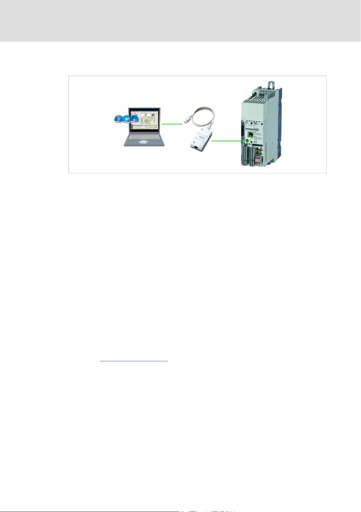
8400 HighLine | Parameter setting & configuration
efesotomasyon.com - Lenze
Introduction: Parameterising the controller
2 Introduction: Parameterising the controller
[2-1] Exemplary constellation for parameterising the controller
Being a component of a machine which includes a speed-variable drive system, the
controller needs to be adjusted to its drive task. The controller is adjusted by changing
parameters which are saved in the memory module.
These parameters can optionally be accessed from the keypad, or the L-force »Engineer«,
or a master control via fieldbus communication:
Simply plug in the X400 keypad onto the controller if you would like to use it.
The USB diagnostic adapter, for instance, can be used for the communication between
the PC (including the L-force »Engineer« software) and the controller, see illustration.
The USB diagnostic adapter is the connection between the PC (free USB port) and the
controller (X6 diagnostic interface).
The "CAN on board" CAN interface and the MCI interface are provided for fieldbus
communication and can be used for a communication module (e.g. PROFIBUS).
Tip!
How to obtain/update the L-force »Engineer« software:
• Download from the Internet:
The full version of the »Engineer StateLevel« is provided free of charge. Current
software can be found on the Internet in the "Services & Downloads" area under
http://www.Lenze.com
• Requesting the CD
You can also request the L-force »Engineer« separately on CD free of charge at
your Lenze representative. See the "About Lenze" area on our homepage for e.g.
the corresponding German address.
.
26 L Firmware ≤ 05.00 - DMS 4.2 EN - 02/2010
Page 27

8400 HighLine | Parameter setting & configuration
efesotomasyon.com - Lenze
2.1 General notes on parameters
All parameters for controller parameterising or monitoring are saved as so-called "codes".
The codes are numbered and indicated by the prefix "C" before the code, e.g. "C00002".
In addition, every code has a name and specific attributes:
– Access type (read, write)
–Data type
– Limit values
– Lenze setting (factory-set scaling)
For the sake of clarity, some codes contain "subcodes" for saving parameters. This
Manual uses a slash "/" as a separator between code and subcode, e.g. C00118/3".
According to their functionality, the parameters are divided into three groups:
Parameter group Examples
Setting parameters
Parameters for specifying setpoints and for setting device /
monitoring functions.
Configuration parameters
Parameters for configuring signal connections (function
block interconnections) within the device, e.g. assignment of
the digital input terminals to the control inputs of the
technology application.
Diagnostic/Display parameters
Parameters for displaying device-internal process factors,
current actual values, and status messages, e.g. for
diagnostic purposes. These are read-only parameters.
Introduction: Parameterising the controller
General notes on parameters
C00005
: Application selection
C00012
: Acceleration time - main setpoint
C00169
: Logbook setting
C00604
: Resp. to device overload (Ixt)
: LA_NCtrl: Analog connection list
C00700
C00701
: LA_NCtrl: Digital connection list
C00710
: LA_TabPos: Analog connection list
C00711
: LA_TabPos: Digital connection list
C00052
: Motor voltage
C00137
: Device state
C00150
: Status word
C00165
: Error information
Tip!
The terms "code" and "subcode" generally correspond to the terms "index" and
"subindex" and "parameter" and "subparameter".
2.2 Handling the memory module
All parameters of the drive system are saved in the integrated memory module of the
controller. These include
the parameters of the controller
the parameters of the communication module plugged into the MCI interface
the parameters of the possibly existing safety module (device variant)
When handling the memory module, a distinction is drawn between the following
scenarios:
Firmware ≤ 05.00 - DMS 4.2 EN - 02/2010 L 27
Page 28

8400 HighLine | Parameter setting & configuration
efesotomasyon.com - Lenze
Introduction: Parameterising the controller
Handling the memory module
Delivery
All devices are delivered with a plugged-on memory module.
In the delivery state, the Lenze setting of the parameters is stored in the memory
module.
The memory module can be preconfigured with customer-specific data.
The memory module is available as a spare part - without any data.
During operation
Note!
Automatic saving is explicitly not supported because this significantly reduces
the service life of the memory module.
Plugging and unplugging the memory module results in a message.
Full functionality of the memory module is even provided if the power supply has been
switched off and only the electronic components of the controller are externally
supplied by a 24 V DC voltage, e.g. via the X5/24E terminal.
Parameter sets can be saved manually.
Parameter sets can be loaded manually.
28 L Firmware ≤ 05.00 - DMS 4.2 EN - 02/2010
Page 29

8400 HighLine | Parameter setting & configuration
efesotomasyon.com - Lenze
Introduction: Parameterising the controller
Handling the memory module
Unplugging the memory module
The memory module can be plugged and unplugged during operation. The behaviour
of the device remains basically unchanged because all parameters are available in the
RAM after the device has been started.
Unplugging the memory module during operation results in an error message and
should therefore be avoided.
The device can also be parameterised when the memory module is unplugged. Of
course, the parameter sets cannot be saved to the memory module then (cp. Saving the
parameters to the memory module safe against mains failure ( 29)).
Replacing the controller
In the event of a device replacement, the entire parameter data of an axis can be copied
to the replacement device by "taking along" the memory module, so that additional PC
or keypad operations are not required.
When replacing the controller, the versions of the old device and the new device are of
importance. Before data are actually transferred, the versions are internally checked.
Basically, the following applies:
– Parameter sets of old devices with V 1.0 can be processed on new devices ≥ V1.0
(downward compatibility).
– Parameters of devices with higher versions are not supported on devices with lower
versions. An error message will be issued if the parameter set versions of the two
devices are not compatible.
– Parameter sets of devices with versions that have less functions (e.g. 8400 StateLine)
can be loaded into and executed on devices with versions that have more functions
(e.g. 8400 HighLine). The reverse is not possible!
Saving the parameters to the memory module safe against mains failure
Controller parameter changes via the »Engineer«, the keypad, or a master control via
fieldbus communication will be lost after mains switching of the controller unless the
settings have been explicitly saved.
Execute the "Save all parameter sets
parameter settings to the memory module.
Using the keypad, you can also press function key
" controller command to save the current
( 71)
to save the parameter settings.
Note!
When the device or the external 24 V DC voltage supply is switched on, all
parameters are automatically loaded from the memory module into the main
memory of the controller.
Please observe the following points during the storage process to avoid data
inconsistencies which would result in an error when loading the parameters
from the memory module:
• Do not switch off the supply voltage!
• Do not remove the memory module from the device!
Firmware ≤ 05.00 - DMS 4.2 EN - 02/2010 L 29
Page 30

8400 HighLine | Parameter setting & configuration
efesotomasyon.com - Lenze
Introduction: Parameterising the controller
Handling the memory module
Parameter set transfer using the »Engineer«
When an online connection to the controller has been established, the following transfer
functions can directly be executed via the Toolbar or the Online menu using the L-force
»Engineer«:
Symbol Menu command Shortcut
Download parameter set <F5>
Upload parameter set <F7>
Save parameter set
Tip!
Detailed information on parameter set transfers using the »Engineer« can be
found in the »Engineer« online help.
30 L Firmware ≤ 05.00 - DMS 4.2 EN - 02/2010
Page 31

2.3 Handling the keypad
efesotomasyon.com - Lenze
Use the keypad for quick and simple parameter setting and for displaying current actual
values and device states via the respective display parameters. For this purpose, plug in the
keypad onto the X6 diagnostic interface on the front of the standard device.
Danger!
In general, changing a parameter causes an immediate response in the
controller!
• This may lead to undesirable behaviour on the motor shaft if the controller
has been enabled!
• Setpoint sources, for instance, may switch over all of a sudden (e.g. when
configuring the signal source for the main setpoint).
Certain device commands or settings which may cause critical states of drive
behaviour constitute exceptions. Such parameter changes are only possible if
the controller is inhibited. Otherwise, a corresponding error message will be
issued.
8400 HighLine | Parameter setting & configuration
Introduction: Parameterising the controller
Handling the keypad
Note!
Plugging and unplugging the keypad is possible during operation.
Detailed information on the keypad can be found in the operating instructions
accompanying the keypad!
Firmware ≤ 05.00 - DMS 4.2 EN - 02/2010 L 31
Page 32

8400 HighLine | Parameter setting & configuration
efesotomasyon.com - Lenze
Introduction: Parameterising the controller
Handling the keypad
Menu structure
In the keypad, the parameters are classified into various menus and submenus.
The USER menu includes a selection of frequently used parameters (freely configurable
in C00517
The Code list contains all parameters.
The Go to param function enables you to reach the corresponding parameter directly.
The Logbook logs all errors and their chronological history.
All other menus and submenus in the keypad correspond precisely to the categories
and subcategories which are displayed in the form of buttons on the left hand side of
the All parameters tab in the »Engineer«:
).
Category
Subcategories
[2-2] All parameters tab in the »Engineer«
General operation
1. Use the
– Use the
– Use the
2. Use the
3. Use the
4. Use the navigation keys to set the desired value.
– Use the
– Use the
5. Use the
– Use the
Tip!
/ navigation keys to select the desired menu.
/ navigation keys to reach a higher/lower menu level.
function key to return to the main menu.
/ navigation keys to select the parameter to be set within a submenu.
function key to switch over to the editing mode.
/ navigation keys to move the cursor to the left/right.
/ navigation keys to change the selected digit.
function key to accept the change and to leave the editing mode.
function key to leave the editing mode without accepting the change.
32 L Firmware ≤ 05.00 - DMS 4.2 EN - 02/2010
General information on setting parameters using the »Engineer« can be found in
the »Engineer« online help.
Page 33

3 Commissioning
efesotomasyon.com - Lenze
Danger!
Take all the necessary safety precautions before you carry out the following
commissioning steps and switch the device on!
8400 HighLine | Parameter setting & configuration
Commissioning
Guide
3.1 Guide
Commissioning for test/demonstration purposes
This type of commissioning serves to make the motor rotate in best time for test/
demonstration purposes with as little wiring effort and optimisation as possible.
Commissioning is performed using the X400 keypad which includes a separate "Quick
commissioning" menu with all the parameters required for basic readiness for operation.
Quick commissioning
Commissioning of technology applications
Commissioning the "Actuating drive speed" TA using the keypad
Commissioning the "Actuating drive speed" TA using the »Engineer«
Commissioning the "Table positioning" TA using the »Engineer«
Commissioning the "Switch-off positioning" TA using »Engineer«
Safety instructions with regard to commissioning
( 38)
( 36)
( 43)
( 46)
( 50)
( 60)
3.1.1 Before commissioning
The »Engineer« and the X400 keypad are available as commissioning tools when a Lenze
drive controller has to be commissioned. The question as to which of these two
commissioning tools should be used for a particular instance of commissioning depends
on several factors and cannot be responded to with a globally applicable answer.
For a practiced user, for example, using the keypad during commissioning of a simple drive
task is often the easier method if the convenience and diagnostics options of the
»Engineer« are not needed. Frequently, the complexity of the machinery to be
commissioned determines which is the most suitable commissioning tool.
Some criteria may help you to select the right commissioning tool:
Commissioning using the X400 keypad is suitable
– for simple drive tasks such as quick commissioning for test/demonstration purposes
– and - to a limited degree - for commissioning the "Actuating drive speed" technology
application.
Firmware ≤ 05.00 - DMS 4.2 EN - 02/2010 L 33
Page 34

8400 HighLine | Parameter setting & configuration
efesotomasyon.com - Lenze
Commissioning
Guide
Commissioning using the »Engineer« engineering software is suitable
– for basically every drive task.
The »Engineer« is a tool which will support you throughout the entire life cycle of a
machine - from planning to maintenance. The support includes the online help
integrated into the »Engineer« and the software documentation provided in the
scope of supply of the device.
– Suited in particular for drive tasks with more demanding requirements/more
comprehensive parameter setting.
Tip!
• During operation, the keypad can be plugged anytime and removed again from
the controller.
• The drive controller can remain separated from the three-phase power supply
system if only parameter setting and diagnosis are to take place during
commissioning. In this case, it is sufficient to supply the drive controller from an
external direct-voltage source (U = 24 V).
• Use the drive diagnostic function of the "X400" keypad (if available) and the
LEDs located on the front of the drive controller:
DRIVE READY/ERROR: LED status displays of the device state
CAN-RUN/CAN-ERR: LED status displays for the system bus
( 454)
( 507)
Preconditions for commissioning with the »Engineer«
For commissioning, you need
a PC that satisfies the following requirements:
– processor with 1.4 GHz or higher
– at least 512 MB RAM and 650 MB free hard disc space
– Microsoft® Windows® 2000 operating system (from service pack 2 onwards) or
Windows® XP
the Lenze »Engineer« PC software
a connection to the drive controller
– for example via the X6/USB diagnostic adapter which serves as a diagnostic
interface.
The USB diagnostic adapter is not included in the scope of supply for the drive
controller. It must be appropriately connected to the X6 diagnostic interface ("DIAG"
terminal) of the drive controller and to a free USB port of the PC. The associated
description is contained on the CD accompanying the drive controller.
Tip!
You can find detailed information on the general use of the »Engineer« in the
online help which you can call with [F1].
34 L Firmware ≤ 05.00 - DMS 4.2 EN - 02/2010
If necessary, carry out a software update to bring the engineering software up-todate. You can find more information on this topic in the chapter entitled
"Introduction: Parameterising the controller
". ( 26)
Page 35

8400 HighLine | Parameter setting & configuration
efesotomasyon.com - Lenze
3.1.2 Trouble during commissioning
If the »Engineer« is used, trouble during commissioning can be detected and eliminated
conveniently. Proceed as follows:
Check whether error messages appear in the »Engineer«.
– You can find a description of each possible message in the chapter entitled
"Diagnostics & error management
Check the input terminals for their corresponding setpoints.
Check the signal flow of the application.
– To do this, open the Application Parameters tab and click on the Signal flow button.
The signal flow which is then shown enables a view of the setpoints being applied
and their processing.
Commissioning
Guide
". ( 452)
Firmware ≤ 05.00 - DMS 4.2 EN - 02/2010 L 35
Page 36

8400 HighLine | Parameter setting & configuration
efesotomasyon.com - Lenze
Commissioning
Safety instructions with regard to commissioning
3.2 Safety instructions with regard to commissioning
3.2.1 General safety instructions
In order to prevent injury to persons or damage to material assets
before connecting the mains voltage, check
– The wiring for completeness, short circuit, and earth fault
– The "emergency stop" function of the entire system
– The motor circuit configuration (star/delta) must be adapted to the output voltage
of the controller
– The in-phase connection of the motor
– The direction of rotation or the encoder (if available)
The setting of the most important drive parameters before enabling the controller:
– Is the V/f rated frequency adapted to the motor circuit configuration?
– Are the drive parameters relevant for your application set correctly?
– Is the configuration of the analog and digital inputs and outputs adapted to the
wiring?
3.2.2 Safety instructions with regard to motor operation
Danger!
• For thermal reasons, continuous operation of self-ventilated motors at a low
field frequency and rated motor current is not permissible. If required, a
motor temperature monitoring should be activated with C00585
Motor temperature monitoring (PTC) ( 201)
Brake resistor monitoring (I2xt)
• C00015 must be used to select 87 Hz operation if a delta-connected
asynchronous motor (nameplate data: 400 V
conjunction with a drive controller for a mains voltage of 400 V.
( 202)
/230 V) is to be operated in
36 L Firmware ≤ 05.00 - DMS 4.2 EN - 02/2010
Page 37

8400 HighLine | Parameter setting & configuration
efesotomasyon.com - Lenze
Commissioning
Safety instructions with regard to commissioning
Tip!
In the Lenze setting, the "U/f characteristic linear" operating mode has been set for
motor control. The parameter settings have been set in advance in such a way that,
if the drive controller and 50 Hz asynchronous machine match each other in terms
of performance, the drive controller is immediately ready for operation without
any further parameter setting work and the motor works satisfactorily.
Recommendations for the following application cases:
• If the drive controller and motor differ greatly from each other in terms of
performance
set code C00022 (I
I
Max
• If a higher starting torque is required
set code C00016 (U
3Hz (C00058), the rated motor current I
• For noise optimisation
set code C00018 to "3" (switching frequency 16 kHz
• If a high torque without feedback is to be provided at small speeds, we
recommend the "Vector control" operating mode.
2.0 I
×=
N(motor)
limit in motor mode) to
max
increase) in such a way that, at a field frequency of f =
min
N(Motor)
flows.
sin var
).
Firmware ≤ 05.00 - DMS 4.2 EN - 02/2010 L 37
Page 38

8400 HighLine | Parameter setting & configuration
efesotomasyon.com - Lenze
Commissioning
Quick commissioning
3.3 Quick commissioning
For controlling the controller, please select
keypad control if you want to use the X400 keypad as the control source. You can find
the associated description in the chapter entitled "Keypad control
terminal control if you want to use a setpoint potentiometer as the control source. You
can find the associated description in the chapter entitled "Terminal control
Tip!
Please read up on keypad handling first:
". ( 38)
". ( 41)
Handling the keypad
3.3.1 Keypad control
Commissioning steps
1. Wire the power connections
– Refer to the mounting instructions supplied with the drive controller to find help on
how to correctly design the power connections to match the requirements of your
device.
2. Wire the control connections
Digital inputs at terminal X5 Assignment Info
DI6
DI7
GI 24I
3. Load the Lenze setting into the controller
DI5
DI4
DI3
DI2 DI1
RFR
( 31)
RFR • Controller enabling:
24E
RFR = High
•Error resetting:
RFR = HIGHÌLOW (edge-controlled)
MCTRL: Act. speed val.
C00051
0 rpm
38 L Firmware ≤ 05.00 - DMS 4.2 EN - 02/2010
After the keypad has been plugged in
or the drive controller has been
switched on with the keypad
plugged in, a connection is first
established between the keypad and
the drive controller.
• The process is completed if code
C00051 appears in the display.
• Then press the left function key.
Page 39

8400 HighLine | Parameter setting & configuration
efesotomasyon.com - Lenze
Commissioning
Quick commissioning
Par1 8400 HighLineC
User - Menu
Go to param
Logbook
Quick commissioning
SAVE
4. Set keypad control
Par1 Quick commissioning
Terminals
Keypad
SAVE
MCTRL: Act. speed val.
C00051
0 rpm
Load Lenze setting
C00002/1
EDIT
• Scroll to the bottom from the
"User menu" with the button to
the "Quick commissioning" menu
• Click on right-hand button
• Select the "Keypad" menu
• Click on right-hand button
• Code C00002/1:
–Parameterise "Edit" using the
left function key
–Select value "1" ---> On/Start
and confirm with "OK" function
key on right
During loading the Lenze setting, the
display goes off for a short time.
• With the Lenze setting, the
"Actuating drive speed"
technology application is
implemented.
• When the display reappears, the
main menu is shown.
–The main menu can be set in a
user-defined manner via the
codes C00465 ... C00469.
• Use the left function key to go to
the USER menu
Par1 8400 HighLineC
User - Menu
Go to param
Logbook
Quick commissioning
Quick commissioning
SAVE
Par1 Quick commissioning
Terminals
Keypad
SAVE
Load Lenze setting
C00002/1
EDIT
Select CtrlMode
C00007
EDIT
5. Enable controller:
Set terminal X5/RFR to HIGH potential (reference: X5/24I).
6. Use the keypad to change the motor velocity or
the motor speed by selecting different fixed setpoints:
Keypad Code Subcode Motor speed
Par1 Quick commissioning
Terminals
Keypad
SAVE
< ... >
C00728
C00051
EDIT
C00728 3 Counter-clockwise rotation:
C00051 - Display of actual speed value
• Continue as described in
commissioning point 3:
–"Quick commissioning" menu
–Keypad
–Load Lenze setting
• With the "Bottom" navigation
key, code C00007 for selecting the
control mode is reached:
–Select code C00007 and
parameterise with "Edit"
–Select value "20" ---> "Keypad"
and confirm with "OK".
-199.99 % ..... 0 (from C00011)
Clockwise rotation:
0 ... +199.99 % (from C00011)
Firmware ≤ 05.00 - DMS 4.2 EN - 02/2010 L 39
Page 40

8400 HighLine | Parameter setting & configuration
efesotomasyon.com - Lenze
Commissioning
Quick commissioning
Please observe
– the actual speed value: C00051
– the LEDs on the front LED’s.LED status displays of the device state
( 454)
7. Save parameter settings with in the memory module.
SAVE
Available codes in the "Quick commissioning" menu
If you select suitable and reasonable values for the parameters in this menu, you can
ensure an error-free operation of the controller.
Analog and digital control information (e.g. speed setpoint, CW rotation / CCW rotation)
are selected depending on the setting of C00007
Parameter Display in the keypad Info
C00002/1
C00007
C00728/3
C00011
C00012
C00013
C00015
C00016
C00022
C00087
C00089
C00039/1
C00727/3
C00727/4
C00051 MCTRL: Act. speed val. Current speed value
C00054 Motor curr. Motor current
Highlighted in grey = display parameter
Load Lenze setting Load Lenze setting
Select CtrlMode Selecting the operating mode
nMainSetValue_a Main setpoint (for the "Actuating drive speed" application)
Appl.: Reference speed Reference speed
Accel. time - main setpoint Acceleration time
Decel. time - main setpoint Deceleration time
VFC: V/f base frequency Base frequency
VFC: Vmin boost V
Imax (motor mode) Current limit (in motor mode)
Rated motor speed Rated motor speed
Rated motor freq. Rated motor frequency
Fixed setpt 1 Fixed setpoint JOG1
bSetSpeedCcw Change of direction of rotation
bJogSpeed1 Jog value 1 for motor speed
(e.g. selection through the digital inputs).
boost
min
40 L Firmware ≤ 05.00 - DMS 4.2 EN - 02/2010
Page 41

3.3.2 Terminal control
efesotomasyon.com - Lenze
Commissioning steps
1. Wire the power connections
– Refer to the mounting instructions supplied with the drive controller to find help on
how to correctly design the power connections to match the requirements of your
device.
2. Wire the control connections
Analog inputs at X3 Assignment Terminal control
O1U
GA
8400 HighLine | Parameter setting & configuration
Commissioning
Quick commissioning
A1IA2I
A1UA2U
0...10 V
AR
1k
...
10kWW
"
A1U Setpoint selection
10 V (= 100 %):
1500 rpm (for 4-pole motor)
Wiring of the digital inputs at X5 Assignment Terminal control
DI6
DI7
GI 24I
X5
DI3
DI5
DI4
DI2 DI1
24E
RFR
+
_
DI1 ... DI7: All active = High
Bold type: Minimum wiring needed for
operation
RFR • Controller enabling: RFR = High
•Error resetting:
RFR = HIGHÌLOW (edge-controlled)
DC 24 V
DI1 Fixed frequency 1 ... fixed frequency 3, see table
DI2
below
DI3 DCB
DI4 Direction of rotation counter-clockwise/clockwise
(CCW/CW)
DI5 ... DI7 No function
3. If you are sure that the drive controller is in its as-delivered condition (Lenze setting),
you can skip the following commissioning step. Otherwise, restore the Lenze settings.
We recommend that you use the keypad for this.
MCTRL: Act. speed val.
C00051
0 rpm
After the keypad has been plugged in
or the drive controller has been
switched on with the keypad
plugged in, a connection is first
established between the keypad and
the drive controller.
• The process is completed if code
C00051 appears in the display.
• Then press the left function key.
Firmware ≤ 05.00 - DMS 4.2 EN - 02/2010 L 41
Par1 8400 HighLineC
User - Menu
Go to param
Logbook
Quick commissioning
SAVE
Par1 Quick commissioning
Terminals
Keypad
SAVE
Load Lenze setting
C00002/1
EDIT
• Scroll to the bottom from the
"User menu" with the button to
the "Quick commissioning" menu
• Click on right-hand button
• Select "Terminals" menu
• Click on right-hand button
• Code 00002/1:
–Parameterise "Edit" using the
left function key
–Select value "1" ---> On/Start
and confirm with "OK" function
key on right
Page 42

8400 HighLine | Parameter setting & configuration
efesotomasyon.com - Lenze
Commissioning
Quick commissioning
MCTRL: Act. speed val.
C00051
0 rpm
During loading the Lenze setting, the
display goes off for a short time.
With the Lenze setting, the
"Actuating drive speed" technology
application is implemented.
• When the display reappears, the
main menu is shown.
–The main menu can be set in a
user-defined manner via the
codes C00465 ... C00469.
• Use the left function key to go to
the USER menu
4. Enable drive controller:
Connect X5/RFR to HIGH potential (reference: X5/GI).
5. Use the potentiometer to vary the motor velocity or
motor speed by stipulating different fixed setpoints:
DI2 DI1 Motor speed
0 0 Setpoint from potentiometer
0 1 40 % of C00011 (reference speed)
1 0 60 % of C00011 (reference speed)
1 1 80 % of C00011 (reference speed)
Please observe
– the actual speed value: C00051
– the LEDs on the front LED’s.LED status displays of the device state
( 454)
6. Save parameter settings with in the memory module.
SAVE
42 L Firmware ≤ 05.00 - DMS 4.2 EN - 02/2010
Page 43

8400 HighLine | Parameter setting & configuration
efesotomasyon.com - Lenze
Commissioning the "Actuating drive speed" TA using the keypad
3.4 Commissioning the "Actuating drive speed" TA using the keypad
System constellation
Commissioning
8400 HighLine
W
U
V
M
3~
i
Connections:
• X3/GA: Ground potential (GND) for analogue signals
• X3/AR: Reference voltage (10 V) for analogue signals
• X3/A1U: Input 1 for analogue signals (slider of the setpoint potentiometer R)
• X5/RFR: Controller enable (CINH)
• X6: Slot for keypad/diagnostic interface
X3
A1U
ARGA
R
X5
RFR
RFR24I
DIAG
X6
[3-1] Block diagram for wiring the commissioning example for the "Actuating drive speed" application
1. Prepare the keypad and the controller for commissioning
Inhibit drive controller: Set X5/RFR terminal to LOW level or open contact (see block
diagram [3-1]
for wiring).
Ensure that the mains voltage and the motor cables are wired correctly.
– Check for correct wiring of the supply feeder and the motor cable, even if motor
operation during commissioning is not intended at first.
Plug the keypad onto the controller (diagnostic interface X6).
2. Switch on device
Stop!
Before stipulating a speed setpoint, check whether the brake in the form of a
holding brake on the motor shaft has been released!
Without motor operation
supply.
: Connect the external 24 V supply to X5/24E. Switch on external
Firmware ≤ 05.00 - DMS 4.2 EN - 02/2010 L 43
Page 44

8400 HighLine | Parameter setting & configuration
efesotomasyon.com - Lenze
Commissioning
Commissioning the "Actuating drive speed" TA using the keypad
With motor operation: Switch on mains.
After switch-on, a connection between the keypad and the drive controller is first
established. The process is concluded when code C00051 appears on the display:
Press the left function key to display the main menu of the control software.
3. Load the Lenze setting
In order to achieve a defined device configuration, it is advisable to make sure that the
device is in its original delivery state.
MCTRL: Act. speed val.
C00051
0 rpm
Go to the keypad menu level Quick commissioning Terminal and set the C00002/1
code to the value "1: On / Start".
4. Check the firmware
It is advisable to check the software version (firmware version), especially if an older drive
controller is being used (e.g. one kept in storage by the customer).
All information that only applies to a certain controller software version or higher is
identified accordingly in this documentation.
The software version of the device can be found
– in the line "SW" on the nameplate
– by reading out code C00099
5. Set the reference speed
Set the reference speed of the motor in code C00011
the nameplate of the motor.
Tip!
Also check the other information on the nameplate against the motor data set in
the drive controller. You can find further information in the section entitled "Motor
selection/Motor data". ( 97)
(firmware version)
. The reference speed is shown on
6. Parameterise the technology application
Go to the menu level Applications Actuating drive speed (par.) and enter the
parameter settings of the technology application.
44 L Firmware ≤ 05.00 - DMS 4.2 EN - 02/2010
Page 45

8400 HighLine | Parameter setting & configuration
efesotomasyon.com - Lenze
Commissioning
Commissioning the "Actuating drive speed" TA using the keypad
Short overview of the most important setting parameters:
Parameter Info Lenze setting
Value Unit
C00012 Accel. time - main setpoint 2.000 s
C00013
C00105
C00039/1
C00039/2
C00039/3
7. Optional: Change I/O connection (e.g. terminal assignment)
Decel. time - main setpoint 2.000 s
Deceleration time - quick stop 2.000 s
Fixed setpoint 1 40.00 %
Fixed setpoint 2 60.00 %
Fixed setpoint 3 80.00 %
Possibility 1
: Change control mode in C00007.
– For a detailed description, see chapter entitled "Terminal assignment of the control
modes". ( 274)
Possibility 2
: Change the I/O connection preconfigured in the selected control mode,
using the configuration parameters of the technology application on the menu level
Applications Actuating drive speed (conf.) to do so.
– For a short overview, see chapter entitled "Configuration parameters (short
overview)". ( 289)
8. Save parameters and test the application
Set C00002/11
= "1: On / Start" in order to save all the parameters.
Enable drive controller: Set X5/RFR terminal to HIGH level or close contact (see block
diagram [3-1]
).
The speed can be changed with the setpoint potentiometer ("R", see block diagram [3-
1]).
More detailed information on the technology application:
TA "Actuating drive speed"
Basic signal flow
( 263)
( 262)
Internal interfaces | application block "LA_NCtrl"
Control words wCANDriveControl/wMCIDriveControl
Terminal assignment of the control modes
Setting parameters (short overview)
Configuration parameters (short overview)
Firmware ≤ 05.00 - DMS 4.2 EN - 02/2010 L 45
( 265)
( 273)
( 274)
( 287)
( 289)
Page 46

8400 HighLine | Parameter setting & configuration
efesotomasyon.com - Lenze
Commissioning
Commissioning the "Actuating drive speed" TA using the »Engineer«
3.5 Commissioning the "Actuating drive speed" TA using the »Engineer«
System constellation
8400 HighLine
W
U
V
M
3~
X3
A1U
ARGA
R
X5
RFR
RFR24I
DIAG
X6
X61
X6
i
Connections:
• X3/GA: Ground potential (GND) for analogue signals
• X3/AR: Reference voltage (10 V) for analogue signals
• X3/A1U: Input 1 for analogue signals (slider of the setpoint potentiometer R)
• X5/RFR: Controller enable (CINH)
• X6: Diagnostic interface for communication between PC and drive controller
[3-2] Block diagram for wiring the commissioning example for the "Actuating drive speed" application
1. Prepare drive controller for commissioning
Inhibit drive controller: Set X5/RFR terminal to LOW level or open contact (see block
diagram [3-2]
for wiring)
Ensure that the mains voltage and the motor cables are wired correctly.
– Check for correct wiring of the supply feeder and the motor cable, even if motor
operation during commissioning is not intended at first.
Connect USB diagnostic adapter.
46 L Firmware ≤ 05.00 - DMS 4.2 EN - 02/2010
Page 47

Commissioning the "Actuating drive speed" TA using the »Engineer«
efesotomasyon.com - Lenze
2. Switch on the device
Stop!
Before stipulating a speed setpoint, check whether the brake in the form of a
holding brake on the motor shaft has been released!
8400 HighLine | Parameter setting & configuration
Commissioning
Without motor operation
supply.
With motor operation
3. Start the »Engineer« & establish online connection to drive controller
Follow the menu navigation in the Start-up wizard. Various options regarding the next
steps to be taken are offered in the wizard.
– For example, the option "Do you want to open an existing Engineer project?", which
appears at the beginning. You specify the next steps to be taken by answering Yes or
No.
Add the corresponding components from the catalogue to the project:
– Drive controller 8400 HighLine C
– Communication module
– Application
–Motor
Select the drive controller in the Project view.
Go online.
4. Load the Lenze setting
: Connect the external 24 V supply to X5/24E. Switch on external
: Switch on mains.
In order to achieve a defined device configuration, it is advisable to make sure that the
device is in its original delivery state.
In the workspace, change to the All parameters tab.
Set a value of "1: On / start" for code C00002/1
– After the Lenze setting has been loaded, the "Actuating drive speed" TA has been
preset with the "Terminals 0
5. Check the firmware
It is advisable to check the software version (firmware version), especially if an older drive
controller is being used (e.g. one kept in storage by the customer).
All information that only applies to a certain controller software version or higher is
identified accordingly in this documentation.
The software version of the device can be found
– in the line "SW" on the nameplate
– by reading out code C00099
" control mode.
(firmware version)
in the parameter list.
Firmware ≤ 05.00 - DMS 4.2 EN - 02/2010 L 47
Page 48

8400 HighLine | Parameter setting & configuration
efesotomasyon.com - Lenze
Commissioning
Commissioning the "Actuating drive speed" TA using the »Engineer«
6. Set the reference speed
Change back to Application parameters tab.
In the Reference speed input field (C00011
), enter the reference speed of the motor.
The reference speed is indicated on the motor nameplate.
Tip!
Also check the other information on the nameplate against the motor data set in
the drive controller. You can find further information in the section entitled "Motor
selection/Motor data". ( 97)
7. Parameterise technology application
Open the Application Parameters tab and adapt the setting parameters of the
technology application according to the purpose it is to be used for.
Short overview of the most important setting parameters:
Parameter Info Lenze setting
Value Unit
C00012 Accel. time - main setpoint 2.000 s
C00013
C00105
C00039/1
C00039/2
C00039/3
Decel. time - main setpoint 2.000 s
Deceleration time - quick stop 2.000 s
Fixed setpoint 1 40.00 %
Fixed setpoint 2 60.00 %
Fixed setpoint 3 80.00 %
8. Optional: Change I/O connection (e.g. terminal assignment)
Possibility 1
: Change control mode in the Control mode list field (C00007).
– The corresponding wiring diagram is displayed in a pop-up window if you click the
button right to the list field.
– For a detailed description, see chapter entitled "Terminal assignment of the control
modes". ( 274)
Option 2
: Use the configuration parameters of the technology application to change
the I/O connection preconfigured in the selected control mode.
– For a short overview, see chapter entitled "Configuration parameters (short
overview)". ( 289)
Option 3
: Change the I/O connection in the FB editor on the I/O interconnection level.
9. Save parameters and test application
Save parameter set.
Enable drive controller: Set X5/RFR terminal to HIGH level or close contact (see block
diagram [3-2]
).
The speed can be changed with the setpoint potentiometer ("R", see block diagram [3-
2]).
48 L Firmware ≤ 05.00 - DMS 4.2 EN - 02/2010
Page 49

8400 HighLine | Parameter setting & configuration
efesotomasyon.com - Lenze
Commissioning the "Actuating drive speed" TA using the »Engineer«
More detailed information on the technology application:
Commissioning
TA "Actuating drive speed"
Basic signal flow
( 263)
Internal interfaces | application block "LA_NCtrl"
( 262)
( 265)
Control words wCANDriveControl/wMCIDriveControl
Terminal assignment of the control modes
Setting parameters (short overview)
( 287)
Configuration parameters (short overview)
( 274)
( 289)
( 273)
Firmware ≤ 05.00 - DMS 4.2 EN - 02/2010 L 49
Page 50

8400 HighLine | Parameter setting & configuration
efesotomasyon.com - Lenze
Commissioning
Commissioning the "Table positioning" TA using the »Engineer«
3.6 Commissioning the "Table positioning" TA using the »Engineer«
System constellation
8400 HighLine
DIAG
X5
W
U
V
M
3~
24I24E
RFR
RFR
DI2DI1
DI3
DI5
DI4
PosProfile
PosExecute
DI6
GIDI7
X6
X61
X6
i
A B
p d
Connections:
• X5/RFR: Controller enable
•X5/DI1: Encoder, track A
•X5/DI2: Encoder, track B
• X5/DI3: Left hardware limit switch
• X5/DI4: Right hardware limit switch
• X5/DI5: "PosExecute" function
• X5/DI6, X5/DI7: Operating mode setting (following mode, referencing, manual jog, positioning)
• X6: Diagnostic interface for communication between PC and drive controller
0-Position
+-
20 3010-10-20-30
40
[3-3] Block diagram for wiring the commissioning example for the "Table positioning" application
1. Prepare drive controller for commissioning
Inhibit drive controller: Set X5/RFR terminal to LOW level or open contact (see block
diagram [3-3]
for wiring)
Ensure that the mains voltage and the motor cables are wired correctly.
– Check for correct wiring of the supply feeder and the motor cable, even if motor
operation during commissioning is not intended at first.
Connect USB diagnostic adapter.
50 L Firmware ≤ 05.00 - DMS 4.2 EN - 02/2010
Page 51

2. Switch on the device
efesotomasyon.com - Lenze
Stop!
Before stipulating a speed setpoint, check whether the brake in the form of a
holding brake on the motor shaft has been released!
8400 HighLine | Parameter setting & configuration
Commissioning
Commissioning the "Table positioning" TA using the »Engineer«
Without motor operation
supply.
With motor operation
3. Start the »Engineer« & establish online connection to drive controller
Follow the menu navigation in the Start-up wizard. Various options regarding the next
steps to be taken are offered in the wizard.
– For example, the option "Do you want to open an existing Engineer project?", which
appears at the beginning. You specify the next steps to be taken by answering Yes or
No.
Add the corresponding components from the catalogue to the project:
– Drive controller 8400 HighLine C
– Communication module
– Application
–Motor
Select drive controller in the Project View.
Go online.
4. Load the Lenze setting
: Connect the external 24 V supply to X5/24E. Switch on external
: Switch on mains.
In order to achieve a defined device configuration, it is advisable to make sure that the
device is in its original delivery state.
In the workspace, change to the All parameters tab.
Set a value of "1: On / start" for code C00002/1
– After the Lenze setting has been loaded, the "Actuating drive speed" TA has been
preset with the "Terminals 0
5. Check the firmware
It is advisable to check the software version (firmware version), especially if an older drive
controller is being used (e.g. one kept in storage by the customer).
All information that only applies to a certain controller software version or higher is
identified accordingly in this documentation.
The software version of the device can be found
– in the line "SW" on the nameplate
– by reading out code C00099
" control mode.
(firmware version)
in the parameter list.
Firmware ≤ 05.00 - DMS 4.2 EN - 02/2010 L 51
Page 52

8400 HighLine | Parameter setting & configuration
efesotomasyon.com - Lenze
Commissioning
Commissioning the "Table positioning" TA using the »Engineer«
6. Set the reference speed
Change back to Application parameters tab.
In the Reference speed input field (C00011
The reference speed is indicated on the motor nameplate.
7. Parameterise technology application
Select "Table positioning" in the Application list field.
After selection of the "table positioning" application, the contents of the tab change, e.g.
only the Machine parameters and Profile entry buttons are shown.
8. Set machine parameters
Click on the Machine parameters button in order to change to the dialog level Overview
Machine parameters:
), enter the reference speed of the motor.
Enter parameters in all fields on a yellow background, e.g. gearbox factor, feed constant
and reference speed.
52 L Firmware ≤ 05.00 - DMS 4.2 EN - 02/2010
Page 53

8400 HighLine | Parameter setting & configuration
efesotomasyon.com - Lenze
Commissioning
Commissioning the "Table positioning" TA using the »Engineer«
9. Change functions assigned to digital input terminals
In the constellation under consideration, a two-track encoder is connected to the DI1
terminal (track A) and DI2 terminal (track B). The functions assigned to the digital terminals
DI1 and DI2 therefore have to be reconfigured accordingly:
Go to the Terminal assignment tab.
In the list field Function assignment DI1 and DI2, set "DI1(6)&DI2(7)=FreqIn (2-track)".
– After alteration of the function assignment, the button indicated by the lower arrow
is displayed:
Click on the button indicated by the lower arrow in order to open the parameterising
dialog for the 2-track frequency input:
Firmware ≤ 05.00 - DMS 4.2 EN - 02/2010 L 53
Page 54

8400 HighLine | Parameter setting & configuration
efesotomasyon.com - Lenze
Commissioning
Commissioning the "Table positioning" TA using the »Engineer«
Enter the data (e.g. number of increments) of the encoder which is used.
10. Enter position encoder in code
Go to All Parameters tab.
In C00490
In C00254, set the proportional gain of the position controller to a suitable value (in the
example: Kp = "5.00 1/s"):
, set "Encoder signal FreqIn12":
54 L Firmware ≤ 05.00 - DMS 4.2 EN - 02/2010
Page 55

8400 HighLine | Parameter setting & configuration
efesotomasyon.com - Lenze
Commissioning
Commissioning the "Table positioning" TA using the »Engineer«
11. Set homing
You can find detailed information on the "Referencing" (homing) operating mode in the
chapter entitled "Basic drive functions", subchapter "Homing
Go to the Application parameters tab.
Click on Signal flow button.
". ( 395)
Click on button for referencing in the "MotionControlKernel" block.
Firmware ≤ 05.00 - DMS 4.2 EN - 02/2010 L 55
Page 56

8400 HighLine | Parameter setting & configuration
efesotomasyon.com - Lenze
Commissioning
Commissioning the "Table positioning" TA using the »Engineer«
Click on Referencing mode button.
Select type of homing.
– For the example, a simple homing movement has been selected without touch
probe. The right limit switch is approached and then the zero position is approach,
depending on the set reference value.
Parameterise fields highlighted in yellow:
– Set suitable starting speed (C01224/1
– Set the reference value (C01227/1
from the right-hand limit position.
).
), i.e. the value in the positive or negative direction
56 L Firmware ≤ 05.00 - DMS 4.2 EN - 02/2010
Page 57

8400 HighLine | Parameter setting & configuration
efesotomasyon.com - Lenze
Commissioning
Commissioning the "Table positioning" TA using the »Engineer«
Select "Referencing" mode via terminals.
– At inputs DI5 and DI6 the profile is set via terminals. With DI5=FALSE and DI6=TRUE
the operating mode is set to "Homing".
–With C01241
checked in the "MotionControlKernel" function block ("Signal flow" button) on the
basis of the position of the switch shown (see arrow:
, the status of the operating mode can be read out and/or it can be
Start referencing:
– Enable drive controller: Set X5/RFR terminal to HIGH level or close contact (see block
diagram [3-3]
– Set DI7 input to HIGH level ("Alternative function PosExecute").
Conclude homing when homing position has been reached:
– Reset DI7 input to LOW level.
– Inhibit drive controller again: Reset X5/RFR terminal to LOW level or open contact
(see block diagram [3-3]
12. Enter one or more profiles
You can find detailed information on entering profiles in the chapter entitled "Basic drive
functions", subchapter "Profile entry". ( 418)
In order to open the profile input window, go to the Application Parameters tab and
select the dialog level Overview Signalflow. Here, click on the Profile input button.
).
).
Note!
In the Lenze setting, profiles 0, 1 and 2 are assigned to the speed follower,
referencing and manual jog operating modes. The other profiles, namely 3 ... 15,
are available for positioning tasks. Operating mode change with profile
number ( 382)
Firmware ≤ 05.00 - DMS 4.2 EN - 02/2010 L 57
Page 58

8400 HighLine | Parameter setting & configuration
efesotomasyon.com - Lenze
Commissioning
Commissioning the "Table positioning" TA using the »Engineer«
Go to Profile numbers list field, a select a number ≥ 3.
– Parameterise the fields required
– If required, enter the sequence profile
– Then press "Back" button (at the top of the tab)
13. Start positioning
You can find detailed information on the "positioning" operating mode in the chapter
entitled "Basic drive functions", subchapter "Positioning
DI5 = HIGH level, DI6 = HIGH level: positioning operating mode
– The status switch displayed in the MotionControlKernel (see "Signal flow") now
adopts the following position:
Enable drive controller: Set X5/RFR terminal to HIGH level or close contact (see block
diagram [3-3]
).
". ( 414)
Set DI7 input to HIGH level ("Alternative function PosExecute").
58 L Firmware ≤ 05.00 - DMS 4.2 EN - 02/2010
Page 59

8400 HighLine | Parameter setting & configuration
efesotomasyon.com - Lenze
Commissioning the "Table positioning" TA using the »Engineer«
More detailed information on the technology application:
Commissioning
TA "Table positioning"
Basic signal flow
Internal interfaces | Application block "LA_TabPos"
( 291)
( 292)
( 295)
Control words wCANDriveControl/wMCIDriveControl
Terminal assignment of the control modes
Setting parameters (short overview)
( 321)
Configuration parameters (short overview)
( 305)
( 322)
( 304)
Firmware ≤ 05.00 - DMS 4.2 EN - 02/2010 L 59
Page 60

8400 HighLine | Parameter setting & configuration
efesotomasyon.com - Lenze
Commissioning
Commissioning the "Switch-off positioning" TA using »Engineer«
3.7 Commissioning the "Switch-off positioning" TA using »Engineer«
System constellation
8400 HighLine
W
UV
M
3~
X5
DI5
DI6
DI5
DI6
DI6
DI3
DI3
DI4
DI1DI2
DI4
0
0
1
0
0
1
1
1
DI5
DI2
DI1
QSP
Cw
Ccw
-
DI2
X5
RFR
DI1
RFR
24I
DIAG
X6
X61
X6
i
DI2DI1
DI6 DI5
v [m/s]
C39/3
C12
C13
C39/2
C12
C13
C39/2
C39/3
Example: Way in which sequential positioning with pre-switch off functions
• The drive controller is enabled with X5/RFR = TRUE and started with X5/DI3 = TRUE in clockwise rotation (Cw).
• The drive accelerates along the acceleration ramp (C00012
• At the DI2 contact, the drive brakes along the deceleration ramp (C00013
with C00039/2
• After reaching the DI1 contact, the drive comes to a stop with quick stop (QSP) in the target position.
• When X5/DI4 = TRUE (X5/DI3 = FALSE), counter-clockwise rotation (Ccw) is started.
• The drive is accelerated along the acceleration ramp (C00012
C00039/3
• At the DI6 contact, the drive brakes along the deceleration ramp (C00013
with C00039/2
• After reaching the DI5 contact, the drive comes to a stop in the initial position with quick stop (QSP).
[3-4] Block diagram for wiring of the commissioning example for the "Switch-off positioning" application
.
.
.
) to the traversing speed set with C00039/3.
) until it reaches the creeping speed set
) until it reaches the traversing speed set with
) until it reaches the creeping speed set
t [s]
60 L Firmware ≤ 05.00 - DMS 4.2 EN - 02/2010
Page 61

8400 HighLine | Parameter setting & configuration
efesotomasyon.com - Lenze
Commissioning
Commissioning the "Switch-off positioning" TA using »Engineer«
Tip!
• If you wish to implement switch-off positioning without
with the control mode "Terminals 2
• In order to avoid positioning inaccuracy due to signal propagation delays, the
initiators can be directly evaluated by the drive controller. Limit switch
evaluation can be configured in the drive controller. With code C0488/x
can change the method of detecting position signals from level evaluation to
edge evaluation.
• In order to prevent unintended movements of the load in the target position,
the use of a holding brake is recommended as an alternative to DC-injection
braking (limited torque).
• The device terminals and their functional assignment do not appear in the FB
editor. The assignment of (hardware) terminals to (software) functions is
explained in the chapter entitled "Terminal assignment of the control modes
( 337)
" is the best method. ( 339)
pre-switch off, wiring
, you
".
1. Prepare the controller and the »Engineer« for commissioning
Inhibit drive controller: Set X5/RFR terminal to LOW level or open contact (see block
diagram [3-4]
Ensure that the mains voltage and the motor cables are wired correctly.
– Check for correct wiring of the supply feeder and the motor cable, even if motor
operation during commissioning is not intended at first.
Connect USB diagnostic adapter.
2. Switch on the device
for wiring)
Stop!
Before stipulating a speed setpoint, check whether the brake in the form of a
holding brake on the motor shaft has been released!
Without motor operation
supply.
With motor operation
: Connect the external 24 V supply to X5/24E. Switch on external
: Switch on mains.
Firmware ≤ 05.00 - DMS 4.2 EN - 02/2010 L 61
Page 62

8400 HighLine | Parameter setting & configuration
efesotomasyon.com - Lenze
Commissioning
Commissioning the "Switch-off positioning" TA using »Engineer«
3. Start the »Engineer« & establish online connection to drive controller
Follow the menu navigation in the Start-up wizard. Various options regarding the next
steps to be taken are offered in the wizard.
– For example, the option "Do you want to open an existing Engineer project?", which
appears at the beginning. You specify the next steps to be taken by answering Yes or
No.
Add the corresponding components from the catalogue to the project:
– Drive controller 8400 HighLine C
– Communication module
– Application
–Motor
Select the drive controller in the Project view.
Go online.
4. Load the Lenze setting
In order to achieve a defined device configuration, it is advisable to make sure that the
device is in its original delivery state.
In the workspace, change to the All parameters tab.
Set a value of "1: On / start" for code C00002/1
– After the Lenze setting has been loaded, the "Actuating drive speed" TA has been
preset with the "Terminals 0
5. Check the firmware
It is advisable to check the software version (firmware version), especially if an older drive
controller is being used (e.g. one kept in storage by the customer).
All information that only applies to a certain controller software version or higher is
identified accordingly in this documentation.
The software version of the device can be found
– in the line "SW" on the nameplate
– by reading out code C00099
6. Set the reference speed
" control mode.
(firmware version)
in the parameter list.
Change back to Application parameters tab.
In the Reference speed input field (C00011
The reference speed is indicated on the motor nameplate.
62 L Firmware ≤ 05.00 - DMS 4.2 EN - 02/2010
), enter the reference speed of the motor.
Page 63

8400 HighLine | Parameter setting & configuration
efesotomasyon.com - Lenze
Commissioning the "Switch-off positioning" TA using »Engineer«
7. Parameterise technology application
Commissioning
Go to the "Application Parameters" tab and select the technology application "Switch-
off positioning", C00005 (= 3000)
application.
Select the control mode appropriate to the application.
–The control mode (C00007
application is to be controlled and how the digital and analog inputs are outputs are
preset.
– In this example, switch-off positioning with
appropriate control mode Terminals 11
the block diagram [3-4]
8. Optional: Change I/O connection (e.g. terminal assignment)
Possibility 1
– The corresponding wiring diagram is displayed in a pop-up window if you click the
– For a detailed description, see chapter entitled "Terminal assignment of the control
modes". ( 274)
Option 2
the I/O connection preconfigured in the selected control mode.
– For a short overview, see chapter entitled "Configuration parameters (short
overview)". ( 289)
: Change control mode in the Control mode list field (C00007).
button right to the list field.
: Use the configuration parameters of the technology application to change
.
. The contents of the tab are then adapted to the set
) is used to determine the source from which the
feedforward control is described. The
is selected and has been wired according to
Option 3
Firmware ≤ 05.00 - DMS 4.2 EN - 02/2010 L 63
: Change the I/O connection in the FB editor on the I/O interconnection level.
Page 64

8400 HighLine | Parameter setting & configuration
efesotomasyon.com - Lenze
Commissioning
Commissioning the "Switch-off positioning" TA using »Engineer«
9. Save parameters and test application
See Example: Way in which sequential positioning
with pre-switch off functions ( 60)
If necessary, parameterise the following codes
Parameter Info
C00012 Acceleration time These settings are only valid if no other ramp times have
C00013 Deceleration time
C00039/2 Fixed setpoint 2 (creeping speed) Fixed setpoint 2 must be less than fixed setpoint 3!
C00039/3 Fixed setpoint 3 (traversing speed)
been selected at the downstream "L_NSet" function block!
Otherwise, the drive will start at a low speed and accelerate
after the pre-switch off.
Tip!
• Low-jerk traversing profiles can be implemented by means of S-shaped ramps.
• In the case of high breakaway torques during horizontal motion sequences, the
user of a vector-controlled drive is recommended.
• For reversal of rotation direction (bidirectional motion), comprehensive
configuration options are available in the drive controller (e.g. by means of the
L_DFlipFlop
More detailed information on the technology application:
) function block
TA "Switch-off positioning"
Basic signal flow
( 327)
Internal interfaces | application block "LA_SwitchPos"
Control words wCANDriveControl/wMCIDriveControl
Terminal assignment of the control modes
Setting parameters (short overview)
Configuration parameters (short overview)
( 325)
( 328)
( 336)
( 337)
( 351)
( 353)
64 L Firmware ≤ 05.00 - DMS 4.2 EN - 02/2010
Page 65

8400 HighLine | Parameter setting & configuration
efesotomasyon.com - Lenze
4 Device control (DCTRL)
This chapter provides information on internal device control as well as the device
commands which can be executed via the subcodes of C00002
The device control causes the controller to take defined device states.
The device control provides a multitude of status information in many ways:
– Visually via the LED status displays
– As text messages in the Logbook
– As process signals via the outputs of the LS_DriveInterface
– Via diagnostic / display parameters which are included in the »Engineer« parameter
list as well as in the Diagnostics category in the keypad.
Note!
The device states of the controller are based on the operating statuses of the
CiA402 standard. Device states
Device control (DCTRL)
.
on the front of the controller. ( 454)
. ( 460)
system block. ( 91)
( 76)
Firmware ≤ 05.00 - DMS 4.2 EN - 02/2010 L 65
Page 66

8400 HighLine | Parameter setting & configuration
efesotomasyon.com - Lenze
Device control (DCTRL)
How to get to the parameterisation dialog of the device control:
1. In the »Engineer«, go to Project view and select the 8400 controller.
2. Go to Workspace and change to the Application parameters tab.
3. Go to the Overview dialog level and click the Drive interface button.
Parameterisation dialog in the »Engineer«
The parameterisation dialog shows the input / output signals and the internal signal flow
of the LS_DriveInterface
block editor:
system block which displays the device control in the function
Range / Meaning Display parameter
Display of the control word via system bus (CAN) C00136/2
Display of the control word via communication module (e.g. PROFIBUS) C00136/1
Display of the internal state machine and the current device state C00137
Display of all active sources of a controller inhibit C00158
Display of all active sources of a quick stop C00159
Display of the status word of the device control C00150
66 L Firmware ≤ 05.00 - DMS 4.2 EN - 02/2010
Page 67

4.1 Controller commands
efesotomasyon.com - Lenze
The following subchapters describe the controller commands which are provided in the
subcodes of C00002
»Engineer« when an online connection has been established.
The controller commands serve to directly control the controller, to organise parameter
sets, and to call diagnostic services.
Regarding the execution of the controller commands, a distinction is drawn between:
Controller commands which have an immediate effect on control (e.g. "Activate quick
stop")
– After being called in C00002/x
information ("On" or "Off").
Controller commands with longer execution durations (several seconds)
– After being called in C00002/x
information ("Work in progress 20%" "Work in progress 40%", etc.).
– The execution of the controller command has not finished successfully until the "Off
/ ready" status information is provided in C00002/x
– In the event of an error, the "Action cancelled" status information is provided in
C00002/x
controller command executed last which is displayed in C00003
. In this case, further details can be obtained from the status of the
8400 HighLine | Parameter setting & configuration
Device control (DCTRL)
Controller commands
and can be carried out using the keypad or, alternatively, the
, these controller commands provide static status
, these controller commands provide dynamic status
.
.
Stop!
Before the supply voltage is switched off after a controller command has been
transmitted via C00002/x
successful completion on the basis of the status information provided in
C00002/x
• This is of particular importance for controller commands which save data to
the memory module of the device. Incomplete storage processes may lead to
data inconsistencies in the memory module.
!
, the controller command must be checked for
Note!
The device will reject a write process to C00002/x if the value is >1 and issue an
error message.
C00003
displays the status of the controller command executed last.
Detailed information on the various controller commands can be found in the
following subchapters.
• Before you follow the instructions given therein, ensure that you have
selected the controller in the Project view.
Firmware ≤ 05.00 - DMS 4.2 EN - 02/2010 L 67
Page 68

8400 HighLine | Parameter setting & configuration
efesotomasyon.com - Lenze
Device control (DCTRL)
Controller commands
Controller commands - short overview
C00002
Subcode:
* Subcodes which are not listed are reserved for future extensions.
Controller command Controller inhibit
required
1 Load Lenze setting
6 Load all parameter sets
11 Save all parameter sets
16 Enable/Inhibit controller
17 Activate/Deactivate quick stop
19 Reset error
21 Delete logbook
23 Identify motor parameter
26 CAN reset node
Status information
z dynamic
z dynamic
dynamic
static
static
static
static
z dynamic
static
Activate controller command
When an online connection has been established, you can simply use the »Engineer« to
activate a controller command by selecting the corresponding option from the Parameters
tab in C00002/x
("0: Off" or "1: On / start").
Alternatively, the controller command can also be activated via e.g. keypad or through
a master control by writing to C00002/x
.
Some of the frequently used controller commands (such as "Save parameter set") can
also be executed via toolbar icons of the »Engineer« when an online connection has
been established:
Symbol Function
Enable controller
Inhibit controller
Save parameter set (for 8400: Save all parameter sets)
Note!
Controller commands that can be executed via the toolbar of the »Engineers«
always affect the element currently selected in the Project view including all
subelements!
• If no controller, but e.g. a system module is selected in the Project view, the
corresponding controller command will be activated in all lower-level
controllers having an online connection with the »Engineer«.
Before the desired action is carried out, a confirmation prompt appears first,
asking whether the action is really to be carried out.
68 L Firmware ≤ 05.00 - DMS 4.2 EN - 02/2010
Page 69

4.1.1 Load Lenze setting
efesotomasyon.com - Lenze
8400 HighLine | Parameter setting & configuration
Device control (DCTRL)
Controller commands
The C00002/1
setting which are saved in the controller Firmware.
Can only be executed if the controller is inhibited; otherwise, the feedback C00002/
1 = "6: No access - controller inhibit" will be returned.
All parameter changes which have been carried out after the last time the parameter
set was saved will be lost!
This controller command has an effect on the settings of the parameters of the
operating system, application and module.
= "1: On / start" controller command resets the parameters to the Lenze
How to load the Lenze setting:
1. If the controller is enabled, it must be inhibited, e.g. by executing the "Enable/
Inhibit controller" controller command (C00002/16
2. Execute the "Load Lenze setting" controller command:
C00002/1
The loading process may take a couple of seconds. After the controller command
has been called in C00002/1
"Work in progress 40%" "Work in progress 60%", etc.) is returned.
= "1: On / start"
, dynamic status information ("Work in progress 20%"
= "0: Off / ready").
Firmware ≤ 05.00 - DMS 4.2 EN - 02/2010 L 69
Page 70

8400 HighLine | Parameter setting & configuration
efesotomasyon.com - Lenze
Device control (DCTRL)
Controller commands
4.1.2 Load all parameter sets
The C00002/6
memory module to the controller.
Can only be executed if the controller is inhibited; otherwise, the feedback C00002/
6 = "6: No access - controller inhibit" will be returned.
All parameter changes which have been carried out after the last time the parameter
set was saved will be lost!
This controller command has an effect on the settings of the parameters of the
operating system, application and module.
= "1: On / start" controller command reloads all parameter settings from the
How to load the parameter settings from the memory module:
1. If the controller is enabled, it must be inhibited, e.g. by executing the "Enable/
Inhibit controller" controller command (C00002/16
2. Execute the "Load all parameter sets" controller command:
C00002/6
The loading process may take a couple of seconds. After the controller command
has been called in C00002/6
"Work in progress 40%" "Work in progress 60%", etc.) is returned.
= "1: On / start"
, dynamic status information ("Work in progress 20%"
= "0: Off / ready").
70 L Firmware ≤ 05.00 - DMS 4.2 EN - 02/2010
Page 71

4.1.3 Save all parameter sets
efesotomasyon.com - Lenze
If parameter settings are changed in the controller, those changes will be lost after mains
switching of the controller unless the settings have been saved explicitly.
8400 HighLine | Parameter setting & configuration
Device control (DCTRL)
Controller commands
The C00002/11
safe against mains failure to the memory module of the controller.
= "1: On / start" controller command saves the current parameter settings
Note!
When the device is switched on, all parameters are automatically loaded from
the memory module to the main memory of the controller.
Observe the following to avoid data inconsistencies which cause errors when the
parameters are loaded from the memory module:
During the storage process:
• Do not switch off the supply voltage!
• Do not remove the memory module from the device!
The controller is currently provided with one
every parameter has a value. Several data records per controller are in
preparation.
How to save the parameter settings to the memory module:
Execute the Save all parameter sets controller command:
C00002/11
= "1: On / start"
data record for all parameters, i.e.
The storage process may take a couple of seconds. After the controller command
has been called in C00002/11
20%" "Work in progress 40%" "Work in progress 60%", etc.) is returned.
, dynamic status information ("Work in progress
Tip!
• This controller command can also be activated via the toolbar icon.
•The "Load Lenze setting
the parameter settings to the delivery status of the device.
" controller command (C00002/1 = "1: On / start") resets
Firmware ≤ 05.00 - DMS 4.2 EN - 02/2010 L 71
Page 72

8400 HighLine | Parameter setting & configuration
efesotomasyon.com - Lenze
Device control (DCTRL)
Controller commands
4.1.4 Enable/Inhibit controller
The C00002/16
= "1: On / start" controller command enables the controller, provided that
no other source of a controller inhibit is active.
The C00002/16
= "0:Off / finished" controller command serves to inhibit the drive
controller, i.e. the power output stages in the drive controller are inhibited and the speed/
current controller of the motor control is reset.
The motor becomes torqueless and coasts, if it has not yet been in standstill.
When the controller is inhibited, the status output bCInhActive of the LS_DriveInterface
system block is set to TRUE.
When the controller inhibit request is reset, the drive synchronises to the actual speed.
For this purpose,
– If the flying restart circuit is activated in C00990
parameterised in C00991
drive. Flying restart function
is used for the synchronisation to the rotary or standing
( 171)
, the flying restart function
– In the case of an operation with feedback, the actual speed is read out by the encoder
system.
– In the case of a sensorless vector control (SLVC), the actual speed from the motor
model of the motor control is used for the synchronisation.
C00158
provides a bit coded representation of all active sources/triggers of a controller
inhibit:
Bit Cause/Source of controller inhibit
Bit 0 Terminal controller enable
Bit 1 CAN control word
Bit 2 MCI control word
Bit 3 SwitchOn
Bit 4 Application (LS_DriveInterface
Bit 5 Device command (C00002/16)
Bit 6 Error with a "Fault"/"Trouble" error response or system error, respectively
Bit 7 Internal signal
Bit 8 Reserved
Bit 9 Reserved
Bit 10 AutoStartLock
Bit 11 Motor parameter identification
Bit 12 Automatic brake operation
Bit 13 DCB-IMP
Bit 14 Reserved
Bit 15 Reserved
system block: bCInh input)
Tip!
The controller can also be enabled or inhibited via the and toolbar icons.
72 L Firmware ≤ 05.00 - DMS 4.2 EN - 02/2010
Page 73

8400 HighLine | Parameter setting & configuration
efesotomasyon.com - Lenze
4.1.5 Activate/Deactivate quick stop
Device control (DCTRL)
Controller commands
The C00002/17
= "1: On / start" controller command activates the quick stop function, i.e.
the motor control is separated from the setpoint selection, and within the deceleration
time parameterised inC00105
Parameter Info Lenze setting
C00105 Deceleration time - quick stop 2.000 s
the motor is brought to a standstill (n
=0).
ist
Value Unit
The motor is kept at a standstill during closed-loop operation.
A pulse inhibit (CINH) is set if the auto-DCB function has been activated via C00019
The C00002/17
= "0: Off / ready" controller command deactivates the quick stop again,
.
provided that no other source of a quick stop is active.
C00159
provides a bit coded representation of all active sources/triggers of a quick
stop:
Bit Cause/Source of controller inhibit
Bit 0 Reserved
Bit 1 CAN control word (bit 2)
Bit 2 MCI control word (bit 2)
Bit 3 Reserved
Bit 4 Application (LS_MotorInterface
Bit 5 Device command (C00002/17)
Bit 6 Device error with "TroubleQSP" error response
Bit 7 Internal signal
Bit 8 Reserved
Bit 9 Reserved
Bit 10 Operating system
Bit 11 Reserved
Bit 12 MCK (System block LS_MotionControlKernel
Bit 13 Reserved
Bit 14 Reserved
Bit 15 Reserved
system block: bQspOn input)
: Input bQspOn)
Firmware ≤ 05.00 - DMS 4.2 EN - 02/2010 L 73
Page 74

8400 HighLine | Parameter setting & configuration
efesotomasyon.com - Lenze
Device control (DCTRL)
Controller commands
4.1.6 Reset error
The C00002/19
message if the error cause has been eliminated and thus the error is not pending anymore.
After resetting the current error, further errors may be pending which must be reset as
well.
The status-determining error is displayed in C00168
The current error is displayed in C00170
Tip!
An error message can also be acknowledged by activating the Reset error button in
the Diagnostics tab.
Detailed information on error messages can be found in the "Diagnostics & error
management" chapter. ( 452)
4.1.7 Delete logbook
The C00002/21
= "1: On / start" controller command acknowledges an existing error
.
.
= "1: On / start" controller command deletes all logbook entries.
Tip!
Click the Logbook button in the Diagnostics tab to display the logbook in the
»Engineer«.
In the Logbook dialog box, it is also possible to delete all logbook entries by clicking
the Delete button.
Detailed information on the logbook can be found in the "Diagnostics & error
management" chapter. ( 452)
74 L Firmware ≤ 05.00 - DMS 4.2 EN - 02/2010
Page 75

4.1.8 Identify motor parameter
efesotomasyon.com - Lenze
8400 HighLine | Parameter setting & configuration
Device control (DCTRL)
Controller commands
The C00002/23
the motor parameters.
The device command is only executed when the drive controller is in the "SwitchedON
state.
In order to identify the motor parameters, the controller must be enabled after this
device command.
– After that it changes to the "MotorIdent
– After the execution of the identification, it changes back to the "SwitchedON
state.
Tip!
Detailed information on automatic identification of motor parameters can be
found in the "Automatic motor data identification
(MCTRL).
4.1.9 CAN reset node
The C00002/26
interface of the controller ("CAN on board"), which is required after e.g. changing the data
transfer rate, the node address or the identifiers, respectively.
= "1: On / start" controller command performs automatic identification of
"
" device state.
" device
" subchapter on motor control
( 102)
= "1: On / start" controller command reinitialises the CANopen system bus
Tip!
Detailed information on the CANopen system bus interface "CAN on board" can be
found in the "System bus "CAN on board"
" chapter. ( 500)
Firmware ≤ 05.00 - DMS 4.2 EN - 02/2010 L 75
Page 76

8400 HighLine | Parameter setting & configuration
Warning
6
efesotomasyon.com - Lenze
Device control (DCTRL)
Device states
4.2 Device states
The state machine causes the controller to take defined states:
Power on
Init
1
0
SystemFault
11
0
SafeTorqueOff
10
Firmware
Update
0
0
ReadyToSwitchON
3
SwitchedOn
4
Fault
8
OperationEnabled
5
1
Warning
6
MotorIdent
2
Pulse inhibit (grey field)
Can be reached from all states.
"Warning" contradicts the definition of a device state. In fact, it is a message which is to call attention to the
device state the warning exists for.
"Warning" can occur in parallel to other states.
[4-1] Device state machine
The arrows between the device states mark the points where the possible device states
begin and end.
The digits stand for the state ID (see table below).
Trouble
7
TroubleQSP
9
76 L Firmware ≤ 05.00 - DMS 4.2 EN - 02/2010
Page 77

8400 HighLine | Parameter setting & configuration
efesotomasyon.com - Lenze
Device control (DCTRL)
Device states
The change from one state to the other is carried out within one processing cycle, i.e.
within t = 1 ms. If within this time there are several requests for state changes, the
state with the higher priority is processed first (see table below).
C00137
C00150
displays the current device state.
(status word) provides a bit coded representation of the current device state
via bits 8 ... 11 (see table below).
ID Device state
(Display in C00137
0 FirmwareUpdate
1 Init
2 MotorIdent
3 ReadyToSwitchON
4 SwitchedON
5 OperationEnabled
6 Warning
7 Trouble
8 Fault
9 TroubleQSP
10 SafeTorqueOff
11 SystemFault
[4-1] Device states, priorities, and meaning of the status bits in the status word
Priority Status bits
)
- 0 0 0 0 Firmware update function is active
- 0 0 0 1 Initialisation is active
- 0 0 1 0 Motor parameter identification is
Prio 8 0 0 1 1 Device is ready to start
Prio 7 0 1 0 0 Device is switched on
Prio 4 0 1 0 1 Operation
- 0 1 1 0 Warning / warning locked is active
Prio 6 0 1 1 1 Trouble is active
Prio 10 1 0 0 0 Fault is active
Prio 5 1 0 0 1 TroubleQSP is active
Prio 9 1 0 1 0 Safe torque off is active
Prio 11 1 0 1 1 System fault is active
(Display in C00150
Bit 11 Bit 10 Bit 9 Bit 8
Meaning
)
active
4.2.1 FirmwareUpdate
Note!
This function may only be executed by qualified Lenze personnel!
Firmware ≤ 05.00 - DMS 4.2 EN - 02/2010 L 77
Page 78

8400 HighLine | Parameter setting & configuration
efesotomasyon.com - Lenze
Device control (DCTRL)
Device states
4.2.2 Init
LED DRIVE READY LED DRIVE ERROR Display in C00137 Display in status word 1 (C00150)
Off Off Init 0001
The controller is in this state immediately after switching on its 24 V supply voltage.
In the "Init" state, the operating system is initialised and all device components
(communication module, memory module, power section, etc.) are identified. When
identifying the power section, it is checked first if it is switched on or if the required voltage
lies within the tolerance zone, respectively.
The inverter is inhibited, i.e. the motor terminals (U, V, W) of the inverter are
deenergised.
The digital and analog inputs are not yet evaluated at this time.
The bus systems (CAN, PROFIBUS etc.) do not work yet, i.e. communication is not
possible.
Bit 11 Bit 10 Bit 9 Bit 8
The application is not yet processed.
The monitoring functions are not yet active.
The controller cannot be parameterised yet and no device commands can be carried out
yet.
Note!
If the 24V voltage supply is in the valid range (>19V) and the initialisation is
finished, the device changes automatically to the "ReadyToSwitchON
If only the 24V voltage supply is available during the mains connection, the error
message "LU: Undervoltage in the DC bus
drive controller.
" state.
" is also entered into the logbook of the
78 L Firmware ≤ 05.00 - DMS 4.2 EN - 02/2010
Page 79

4.2.3 MotorIdent
efesotomasyon.com - Lenze
LED DRIVE READY LED DRIVE ERROR Display in C00137 Display in status word 1 (C00150)
The controller has been provided with a function for automatic identification of the motor
parameters. If the motor parameter identification is active, the controller is in the
"MotorIdent" device state.
Stop!
During motor parameter identification, the controller does not respond to
setpoint changes or control processes, (e.g. speed setpoints, quick stop, torque
limitations).
8400 HighLine | Parameter setting & configuration
Device control (DCTRL)
Device states
Bit 11 Bit 10 Bit 9 Bit 8
Off MotorIdent 0 0 1 0
The "MotorIdent" device state can only be reached by the "SwitchedON
and jumps back to that state after the activity has been completed.
The following illustration shows the conditions under which the state change will be
enabled or stopped:
C00002/23 = 1
CINH = 1
SwitchedOn
4
[4-2] Conditions for the state change of the motor identification
While the motor parameters are being detected,
the application remains active,
all system interfaces (IO, bus systems, etc.) remain active,
error monitoring remains active,
the inverter is controlled independently of the setpoint sources.
&
Tip!
" device state
MotorIdent
2
Firmware ≤ 05.00 - DMS 4.2 EN - 02/2010 L 79
Detailed information on motor parameter identification can be found in the
"Automatic motor data identification
" subchapter on motor control. ( 102)
Page 80

8400 HighLine | Parameter setting & configuration
efesotomasyon.com - Lenze
Device control (DCTRL)
Device states
4.2.4 SafeTorqueOff
LED DRIVE READY LED DRIVE ERROR Display in C00137 Display in status word 1 (C00150)
Off SafeTorqueOff 1 0 1 0
Note!
This device state is only possible in connection with an integrated safety system
and if a power section supply is available!
Integrated safety systems with Inverter Drives 8400
Drive controller of the 8400 series can be equipped with the integrated "Safe torque off
(STO)" safety system.
Bit 11 Bit 10 Bit 9 Bit 8
The integrated safety system is applicable on machines for the protection of persons.
The drive function is still carried out by the drive controller. The safety system provides safe
inputs. If the safety system is activated, it executes control functions according to EN
60204-1 directly in the drive controller in case of errors.
Safety state
If the drive controller is switched off by the safety system, the device changes to the
"SafeTorqueOff" state.
If the safety system deactivates the "Safe torque off (STO)" request, the device changes to
the "ReadyToSwitchON
" state.
Detailed information on the integrated safety system can be found in the
hardware manual!
The hardware manual contains important notes on the safety system which
must be observed!
80 L Firmware ≤ 05.00 - DMS 4.2 EN - 02/2010
Page 81

4.2.5 ReadyToSwitchON
efesotomasyon.com - Lenze
LED DRIVE READY LED DRIVE ERROR Display in C00137 Display in status word 1 (C00150)
The controller is in this device state directly after the initialisation has been completed!
The bus systems are running and the terminals and encoders are evaluated.
The monitoring modes are active.
The controller can be parameterised.
The application is basically executable.
Note!
• The "ReadyToSwitchOn" state is not only activated after the mains
connection, but also after the deactivation of "Trouble
"SafeTorqueOff
• If the "Inhibit at power-on" auto-start option has been activated in C00142
(Lenze setting), explicit deactivation of the controller inhibit after mains
connection is always required for the controller to change from the
"ReadyToSwitchOn" status to the "SwitchedON
• If only the 24V voltage supply is available during the mains connection, the
error message "LU: Undervoltage in the DC bus
the drive controller and the drive controller remains in the
"ReadyToSwitchOn" state.
8400 HighLine | Parameter setting & configuration
Device control (DCTRL)
Device states
Bit 11 Bit 10 Bit 9 Bit 8
Off ReadyToSwitchON 0 0 1 1
", "Fault" or
".
" status.
" is entered into the logbook of
Danger!
If the "Inhibit at power-on" auto-start option has been deactivated in C00142,
the "ReadyToSwitchOn" state switches directly to the SwitchedON
mains connection.
Automatic restart after mains connection/fault...
" state after
( 87)
Firmware ≤ 05.00 - DMS 4.2 EN - 02/2010 L 81
Page 82

8400 HighLine | Parameter setting & configuration
efesotomasyon.com - Lenze
Device control (DCTRL)
Device states
4.2.6 SwitchedON
LED DRIVE READY LED DRIVE ERROR Display in C00137 Display in status word 1 (C00150)
Off SwitchedON 0100
The drive is in this device state if the DC bus voltage is applied and the controller is still
inhibited by the user (controller inhibit).
The bus systems are running and the terminals and encoders are evaluated.
The monitoring modes are active.
The application is basically executable.
Bit 11 Bit 10 Bit 9 Bit 8
If the controller inhibit is deactivated, the devices changes to the "OperationEnabled
" state
and the motor follows the setpoint defined by the active application.
Tip!
C00158
controller inhibit.
Depending on certain conditions, a state change takes place based on the "SwitchedOn"
device state:
Change condition Changeover to the device state
Control bit "EnableOperation" of all control channels = "1"
AND terminal RFR = HIGH level (controller enable)
Control bit "SwitchOn" = "0". ReadyToSwitchON
Motor parameter identification requested. MotorIdent
Undervoltage in the DC bus. Trouble/Fault (depending onC00600/1)
Error with error response "Trouble" occurs. Trouble
Error with error response "TroubleQSP" occurs. TroubleQSP
Related topics:
provides a bit coded representation of all active sources/triggers of a
OperationEnabled
wCANControl/wMCIControl control words
82 L Firmware ≤ 05.00 - DMS 4.2 EN - 02/2010
( 94)
Page 83

4.2.7 OperationEnabled
efesotomasyon.com - Lenze
LED DRIVE READY LED DRIVE ERROR Display in C00137 Display in status word 1 (C00150)
The drive controller is in this device state if the controller inhibit is deactivated and no error
("Trouble" or "TroubleQSP") has occured. The operation is enabled and the motor follows
the setpoint defined by the active application.
Depending on certain conditions, a state change takes place based on the
"OperationEnabled" device state.
Change condition Changeover to the device state
Control bit "EnableOperation" of a control channel = "0"
OR terminal RFR = LOW level (controller inhibit).
Control bit "SwitchOn" = "0". ReadyToSwitchON
Undervoltage in the DC bus. Trouble/Fault (depending onC00600/1)
Error with error response "Trouble" occurs. Trouble
Error with error response "TroubleQSP" occurs. TroubleQSP
8400 HighLine | Parameter setting & configuration
Device control (DCTRL)
Device states
Bit 11 Bit 10 Bit 9 Bit 8
Off OperationEnabled0101
SwitchedON
Related topics:
wCANControl/wMCIControl control words
4.2.8 Warning
LED DRIVE READY LED DRIVE ERROR Display in C00137 Display in status word 1 (C00150)
This display may occur in all device states if a monitoring mode responds, the error
response "Warning" or "Warning locked" has been parameterised for.
If the error is no longer active, the previous device state is displayed.
( 94)
Bit 11 Bit 10 Bit 9 Bit 8
Warning 0110
Firmware ≤ 05.00 - DMS 4.2 EN - 02/2010 L 83
Page 84

8400 HighLine | Parameter setting & configuration
efesotomasyon.com - Lenze
Device control (DCTRL)
Device states
4.2.9 TroubleQSP
LED DRIVE READY LED DRIVE ERROR Display in C00137 Display in status word 1 (C00150)
TroubleQSP 1001
This device state will be active as soon as a monitoring mode responds, the error response
"TroubleQSP" has been parameterised for.
The drive is decelerated to standstill with torque within the deceleration time
parameterised for quick stop independently of the defined setpoint and can be kept
there.
The device state can only be abandoned by acknowledging the error if the error cause
is removed.
Bit 11 Bit 10 Bit 9 Bit 8
When the controller is inhibited, it is possible to jump to the "SwitchedON
" state even
during the error state since the controller inhibit function has a higher priority. As long
as the error is pending and has not been acknowledged, the state is changed back to
the "TroubleQSP" state when the controller is enabled afterwards.
Depending on certain conditions a state change takes place based on the "TroubleQSP"
device state.
Change condition Changeover to the device state
Control bit "SwitchOn" = "0". ReadyToSwitchON
Control bit "EnableOperation" of all control channels = "1"
AND terminal RFR = HIGH level (controller enable)
AND error is reset by the control bit "ResetFault"
AND no more errors are pending.
Control bit "EnableOperation" of a control channel = "0"
OR terminal RFR = LOW level (controller inhibit)
AND error is reset by the control bit "ResetFault"
AND no more errors are pending.
A message is active in the system. Trouble
OperationEnabled
SwitchedON
Related topics:
wCANControl/wMCIControl control words
Basics on error handling in the controller
( 94)
( 452)
Error messages of the operating system
84 L Firmware ≤ 05.00 - DMS 4.2 EN - 02/2010
( 471)
Page 85

4.2.10 Trouble
efesotomasyon.com - Lenze
LED DRIVE READY LED DRIVE ERROR Display in C00137 Display in status word 1 (C00150)
This device state becomes active as soon as a monitoring mode responds for which the
error response "Trouble" has been parameterised.
The motor has no torque (is coasting) due to the inhibit of the inverter.
The "Trouble" device state is automatically abandoned if the error cause has been
removed.
Note!
8400 HighLine | Parameter setting & configuration
Device control (DCTRL)
Device states
Bit 11 Bit 10 Bit 9 Bit 8
Off Trouble 0111
If the "Inhibit at trouble" auto-start option has been activated in C00142, explicit
deactivation of the controller inhibit is required before this state can be
abandoned.
Depending on certain conditions a state change takes place based on the "Trouble" device
state.
Change condition Changeover to the device state
The error cause is no longer active. ReadyToSwitchON
Control bit "EnableOperation" of all control channels = "1"
AND terminal RFR = HIGH level (controller enable)
AND the message has been cancelled.
Control bit "EnableOperation" of a control channel = "0"
OR terminal RFR = LOW level (controller inhibit)
AND the message has been cancelled.
In the system, there is an error configured on "TroubleQSP".
AND the message has been cancelled.
OperationEnabled
SwitchedON
TroubleQSP
Related topics:
wCANControl/wMCIControl control words
Basics on error handling in the controller
Error messages of the operating system
( 94)
( 452)
( 471)
Firmware ≤ 05.00 - DMS 4.2 EN - 02/2010 L 85
Page 86

8400 HighLine | Parameter setting & configuration
efesotomasyon.com - Lenze
Device control (DCTRL)
Device states
4.2.11 Fault
LED DRIVE READY LED DRIVE ERROR Display in C00137 Display in status word 1 (C00150)
Off Fault 1000
This device state will be active as soon as a monitoring mode responds, the error response
"Fault" has been parameterised for.
The motor has no torque (is coasting) due to the inhibit of the inverter.
The error must explicitly be reset ("acknowledged") in order to exit the device state, e.g.
by the device command "Reset error
word wCanControl or wMCIControl.
" or via the control bit "ResetFault" in the control
Note!
Bit 11 Bit 10 Bit 9 Bit 8
Related topics:
wCANControl/wMCIControl control words
Basics on error handling in the controller
Error messages of the operating system
4.2.12 SystemFault
If an undervoltage in the DC bus of the drive controller occurs (error message
"LU"), the device changes to the "Trouble
An additional error of higher priority leads the device into the "Fault
According to the Device state machine
"ReadyToSwitchON
undervoltage is still available!
If the "Inhibit at fault" auto-start option has been activated in C00142
deactivation of the controller inhibit is required before the state can be
abandoned.
" state after acknowledging the error although the
( 471)
" state.
" state.
, the device changes to the
, explicit
( 94)
( 452)
LED DRIVE READY LED DRIVE ERROR Display in C00137 Display in status word 1 (C00150)
This device state becomes active if a system fault occurs.
The device state can only be abandoned by
–mains switching or
– a system restart (in preparation).
86 L Firmware ≤ 05.00 - DMS 4.2 EN - 02/2010
Bit 11 Bit 10 Bit 9 Bit 8
Off SystemFault 1011
Page 87

8400 HighLine | Parameter setting & configuration
efesotomasyon.com - Lenze
Automatic restart after mains connection/fault...
4.3 Automatic restart after mains connection/fault...
.../error/undervoltage
Device control (DCTRL)
In C00142
undervoltage, as well as a "Trouble
Auto-start option (C00142) Lenze setting
Bit 4 ... 7 Reserved 0
, the starting performance of the controller after mains connection,
" or a "Fault" reset can be parameterised individually:
Bit 0 Inhibit at power-on 1 ≡ Inhibit is active
Bit 1 Inhibit at trouble 0 ≡ Inhibit is not active
Bit 2 Inhibit at fault 0 ≡ Inhibit is not active
Bit 3 Inhibit at undervoltage 1 ≡ Inhibit is active
Note!
In the Lenze setting , automatic restart after mains connection or undervoltage
is inhibited.
Danger!
If the "Inhibit at power-on" auto-start option has been deactivated in C00142
(bit 0 = 0), a direct change from the "ReadyToSwitchON
"SwitchedON
" state is performed after mains connection!
" state to the
Firmware ≤ 05.00 - DMS 4.2 EN - 02/2010 L 87
Page 88

8400 HighLine | Parameter setting & configuration
efesotomasyon.com - Lenze
Device control (DCTRL)
Automatic restart after mains connection/fault...
"Inhibit at power-on" auto-start option
If the "Inhibit at power-on" auto-start option has been activated in C00142
setting), explicit deactivation of the controller inhibit is always required after mains
connection for the controller to change from the "ReadyToSwitchON
"SwitchedON
" state:
01
RFR
Init SwitchedOn OperationEnabledReadyToSwitchOn
RFR
RFR
Init SwitchedOn OperationEnabledReadyToSwitchOn
RFR
Controller pulses are inhibited
Controller pulses are enabled
noWith controller inhibit during power-up
Without controller inhibit during power-up
[4-3] State changes if the "Inhibit at power-on" auto-start option has been activated (C00142: bit 0 = 1)
(Lenze
" state to the
t
t
The illustration below shows the state changes if auto-restart after mains connection
has been enabled (C00142
RFR
Init SwitchedOn OperationEnabledReadyToSwitchOn
RFR
RFR
Init SwitchedOn OperationEnabledReadyToSwitchOn
RFR
Controller pulses are inhibited
Controller pulses are enabled
noWith controller inhibit during power-up
Without controller inhibit during power-up
[4-4] State changes if the "Inhibit at power-on" auto-start option has been deactivated (C00142: bit 0 = 0)
: bit 0 = 0), depending on the controller inhibit:
01
t
t
88 L Firmware ≤ 05.00 - DMS 4.2 EN - 02/2010
Page 89

8400 HighLine | Parameter setting & configuration
efesotomasyon.com - Lenze
Synchronisation of the internal time base of the controller
4.4 Synchronisation of the internal time base of the controller
In a drive system, synchronising the internal time bases of all controllers involved makes
sense because cyclic process data should be processed synchronously in all drives.
One of the following signal sources can be used for automatic synchronisation of the
internal time base of the controller:
– CAN on board (sync telegram)
– Digital input
– Sync signal of a plugged-in communication module
(EtherCAT, PROFINET, or Powerlink)
Short overview of the parameters for the synchronisation of the internal time base:
Parameter Info Lenze setting
C01120 Sync signal source Off
C01121
C01122
C01123
C01124
Sync cycle time setpoint 1000 μs
Sync phase position 0 μs
Sync window 1000 μs
Sync correction increment 75 ns
Device control (DCTRL)
Value Unit
Sync signal source
The synchronisation signal source can be selected in C01120
. As a general rule, only one
source can be used to synchronise the internal time base.
Sync cycle time setpoint
Time after which the internal phase-locking loop (PLL) anticipates the synchronisation
signals. The time must be set in C01121
source selected in C01120
.
according to the cycle of the synchronisation
Note!
If the system bus is used for synchronisation, only select integer multiples of
1000 μs in C01121
Example: For the system bus, 2 ms has been selected as interval between two
synchronisation signals. If the system bus is to be used as synchronisation source, a sync
cycle time setpoint of 2000 μs must be selected in C01121
Sync phase position
The phase position determines the zero time of the application referred to the
synchronisation signal (bus cycle). Since PDO processing is an integral part of the system
part of the application, a change of the phase position also changes the acceptance time of
the PDO.
.
.
If "0" is set, the application will start at the same time as the synchronisation signal.
Firmware ≤ 05.00 - DMS 4.2 EN - 02/2010 L 89
Page 90

8400 HighLine | Parameter setting & configuration
efesotomasyon.com - Lenze
Device control (DCTRL)
Synchronisation of the internal time base of the controller
If a value > 0 is set, the start of the application will be delayed by the set time, compared
to the synchronisation signal.
Example: If the phase position is set to 400 μs, the system part of the application starts
400 μs after the arrival of the synchronisation signal.
Sync correction increment
If the cycle times of the synchronisation signal and the phase-locking loop (PLL) are
different, the setting in C01124
loop.
The recommended reset time for the system bus as synchronisation source in case of
occurring deviations is 75 ns (Lenze setting).
defines the correction increments for the phase-locking
90 L Firmware ≤ 05.00 - DMS 4.2 EN - 02/2010
Page 91

8400 HighLine | Parameter setting & configuration
efesotomasyon.com - Lenze
Internal interfaces | "LS_DriveInterface" system block
4.5 Internal interfaces | "LS_DriveInterface" system block
The LS_DriveInterface system block displays the device control in the FB Editor.
/6B'ULYH,QWHUIDFH
Device control (DCTRL)
Z&$1&RQWURO
Z0&,&RQWURO
E&,QK
E)DLO5HVHW
E6WDWXVB%LW
E6WDWXVB%LW
E6WDWXVB%LW
E6WDWXVB%LW
E6WDWXVB%LW
E6WDWXVB%LW
E6WDWXVB%LW
E)UHH
E)UHH
E)UHH
E)UHH
&
&
%LW
%LW
%LW
%LW
%LW
%LW
%LW
%LW
%LW
%LW
%LW
&21752/:25'
%LW
%LW
%LW
%LW
%LW
6ZLWFK2Q
'LVDEOH9ROWDJH
6HW4XLFNVWRS
(QDEOH2SHUDWLRQ
0RGH6SHFLILFB
0RGH6SHFLILFB
0RGH6SHFLILFB
5HVHW)DLO
6HW+DOW
UHVHUYHGB
UHVHUYHGB
/HQ]H6SHFLILFB
/HQ]H6SHFLILFB
/HQ]H6SHFLILFB
6HW)DLO
/HQ]H6SHFLILFB
&
48,&.6723
&
(1$%/(',6$%/(
5)5
&
5(6(7)$,/
%LW
)UHH6WDWXV%LW
%LW
3RZHU'LVDEOHG
%LW
)UHH6WDWXV%LW
%LW
)UHH6WDWXV%LW
%LW
)UHH6WDWXV%LW
%LW
)UHH6WDWXV%LW
%LW
$FW6SHHG,V=HUR
%LW
&RQWUROOHU,QKLELW
%LW
6WDWXV&RGH%LW
%LW
6WDWXV&RGH%LW
%LW
6WDWXV&RGH%LW
%LW
6WDWXV&RGH%LW
%LW
:DUQLQJ
%LW
7URXEOH
%LW
)UHH6WDWXV%LW
%LW
)UHH6WDWXV%LW
&6SHHG "
Z6WDWH'HWHUP)DLO1R/RZ
Z6WDWH'HWHUP)DLO1R+LJK
E,QLW
E6DIH7RUTXH2II
E5HDG\
E5HDG\7R6ZLWFK2Q
E2SHUDWLRQ(QDEOH
E:DUQLQJ
E7URXEOH
E)DLO
E&ROOHFWHG)DLO
E6DIHW\,V$FWLYH
E,PS,V$FWLYH
E&,QK,V$FWLYH
E&Z&FZ
E1DFW&RPSDUH
Z'HYLFH6WDWXV:RUG
&
67$786:25'
Firmware ≤ 05.00 - DMS 4.2 EN - 02/2010 L 91
Page 92

8400 HighLine | Parameter setting & configuration
efesotomasyon.com - Lenze
Device control (DCTRL)
Internal interfaces | "LS_DriveInterface" system block
Inputs
Identifier
wCANControl
wMCIControl
bCInh
bFailReset
bStatus_Bit0
bStatus_Bit2
bStatus_Bit3
bStatus_Bit4
bStatus_Bit5
bStatus_Bit14
bStatus_Bit15
DIS code | data type
C00136/2 | WORD
C00136/1 | WORD
C00833/36 | BOOL
C00833/37 | BOOL
C00833/38 ... 44 | BOOL
Information/possible settings
Control word via system bus (CAN)
• The controller controlled by a master control (e.g. IPC) receives its control word by
the CANopen system bus interface. The process data word is provided at this
input by the upstream port block LP_CanIn1
• See the "wCANControl/wMCIControl control words
description of the individual control bits. ( 94)
Control word via communication module (e.g. PROFIBUS)
• The controller controlled by a master control (e.g. IPC) receives its control word by
a plugged-in communication module. The process data word is provided at this
input by the upstream port block LP_MciIn1
• See the "wCANControl/wMCIControl control words
description of the individual control bits. ( 94)
Enable/Inhibit controller ( 72)
FALSE Enable controller: The controller switches to the "OperationEnabled
device state, if no other source of a controller inhibit is active.
• C00158
TRUE Inhibit controller (controller inhibit): The controller switches to the
"SwitchedON
Reset of error message ( 474)
TRUE The current error is reset.
Freely assignable bits in the status word of the controller.
• You can use these bits for returning information to the master control (e.g. IPC).
provides a bit coded representation of all active sources/
triggers of a controller inhibit.
" device state.
.
" chapter for a detailed
.
" chapter for a detailed
"
92 L Firmware ≤ 05.00 - DMS 4.2 EN - 02/2010
Page 93

Outputs
efesotomasyon.com - Lenze
8400 HighLine | Parameter setting & configuration
Device control (DCTRL)
Internal interfaces | "LS_DriveInterface" system block
Identifier
DIS code | data type
wDeviceStatusWord
C00150 | WORD
wStateDetermFailNoLow
wStateDetermFailNoHigh
bInit
bSafeTorqueOff
bReady
bReadyToSwitchOn
bOperationEnable
bWarning
bTrouble
bFault
bCollectedFail
As of version 04.00.00
bSafetyIsActive
bImpIsActive
bCInhIsActive
bCwCcw
bNactCompare
Value/meaning
Status word of the controller (based on DSP-402)
• The status word contains all information relevant for controlling the controller.
• The status word is sent as a process data word to the master control via a port
block:
–Port block LP_CanOut1
–Port block LP_MciOut
when the CANopen system bus interface is used or
when a plugged-in communication module is used (e.g.
PROFIBUS).
• For a detailed description of each status bit see chapter "wDeviceStatusWord
status word". ( 95)
Display of the status determining error (LOW word)
WORD
Display of the status determining error (HIGH word)
WORD
TRUE "Init" device state is active
BOOL
TRUE "SafeTorqueOff" device state is active
BOOL
TRUE "SwitchedON" device state is active
BOOL
TRUE "ReadyToSwitchON" device state is active
BOOL
TRUE "OperationEnabled" device state is active
BOOL
TRUE "Warning" device state is active
BOOL
TRUE "Trouble" device state is active
BOOL
TRUE "Fault" device state is active
BOOL
TRUE Group error: A device state according to the group error
BOOL
configuration in C00148
has occurred, the drive is not able to follow
the setpoint selection.
TRUE In preparation
BOOL
TRUE Pulse inhibit is active
BOOL
TRUE Controller inhibit is active
BOOL
FALSE Motor rotates in CW direction
BOOL
TRUE Motor rotates in CCW direction
TRUE During open-loop operation:
BOOL
Speed setpoint < Comparison value (C00024
)
During closed-loop operation:
Actual speed value < Comparison value (C00024
)
Firmware ≤ 05.00 - DMS 4.2 EN - 02/2010 L 93
Page 94

8400 HighLine | Parameter setting & configuration
efesotomasyon.com - Lenze
Device control (DCTRL)
Internal interfaces | "LS_DriveInterface" system block
4.5.1 wCANControl/wMCIControl control words
The controller is controlled by a master control (e.g. IPC) via the wCanControl or
wMCIControl control word, respectively.
wCANControl: Control word via system bus (CAN)
– The process data word is provided at the wCanControl input via the upstream
LP_CanIn1
– Display parameter: C00136/2
wMCIControl: Control word via a plugged-in communication module (e.g. PROFIBUS)
– The process data word is provided at the wMCIControl input via the upstream
LP_MciIn1
– Display parameter: C00136/1
The bit assignment for the wCanControl/wMCIControl control words can be seen from
the table below.
port block.
port block.
Note!
The assignment of bits 11 ... 13 and bit 15 depends on the technology
application selected in C00005
• See description of the corresponding technology application.
Bit Name Function
Bit 0 SwitchOn 1 ≡ Change to the "SwitchedON
• This bit must be set in the CAN/MCI control word to ensure that the device
changes to the "SwitchedON
the need for a master control specifying this bit via fieldbus.
• If control via a bus system is not wanted (e.g. in the case of control via
terminals), the wDriveCtrl output signal of the LS_ParFix
connected to the control word inputs.
Bit 1 DisableVoltage 1 ≡ Inhibit inverter control (IMP - pulse inhibit)
Bit 2 SetQuickStop Activate quick stop (QSP)
Activate/Deactivate quick stop
Bit 3 EnableOperation 1 ≡ Enable controller (RFR)
• If control via terminals is performed, this bit must be set both in the CAN
control word and in the MCI control word. Otherwise, the controller is
inhibited.
Bit 4 ModeSpecific_1 Reserved (currently not assigned)
Bit 5 ModeSpecific_2
Bit 6 ModeSpecific_3
Bit 7 ResetFault 1 ≡ Reset fault (trip reset)
• Acknowledge fault message (if the error cause has been eliminated).
Bit 8 SetHalt 1 ≡ Activate stop function
• Stop drive via stopping ramp (in preparation).
Bit 9 reserved_1 Reserved (currently not assigned)
Bit 10 reserved_2
Bit 11 LenzeSpecific_1 Assignment depends on the selected technology application
Bit 12 LenzeSpecific_2
Bit 13 LenzeSpecific_3
• See description of the corresponding technology application.
!
" device state
" device state after mains connection without
system block can be
( 73)
94 L Firmware ≤ 05.00 - DMS 4.2 EN - 02/2010
Page 95

8400 HighLine | Parameter setting & configuration
efesotomasyon.com - Lenze
Bit Name Function
Bit 14 SetFail 1 ≡ Set error (trip set)
Bit 15 LenzeSpecific_4 Assignment depends on the selected technology application
• See description of the corresponding technology application.
4.5.2 wDeviceStatusWord status word
The wDeviceStatusWord status word provided by the control system contains all
information relevant for controlling the controller.
The status word is sent as a process data word to the master control via a port block:
–The LP_CanOut1 port block if "CAN on board" is used or
–the LP_MciOut1 port block if a plugged-in communication module is used (e.g.
PROFIBUS).
Display parameter: C00150
The bit assignment of the wDeviceStatusWord status word can be seen from the table
below.
Device control (DCTRL)
Internal interfaces | "LS_DriveInterface" system block
Bit Name Status
Bit 0 FreeStatusBit0 Free status bit 0
Bit 1 PowerDisabled 1 ≡ Inverter control inhibited (pulse inhibit is active)
Bit 2 FreeStatusBit2 Free status bit 2 (not assigned, freely assignable)
Bit 3 FreeStatusBit3 Free status bit 3 (not assigned, freely assignable)
Bit 4 FreeStatusBit4 Free status bit 4 (not assigned, freely assignable)
Bit 5 FreeStatusBit5 Free status bit 5 (not assigned, freely assignable)
Bit 6 ActSpeedIsZero During open-loop operation:
1 ≡ Speed setpoint < Comparison value (C00024
During closed-loop operation:
1 ≡ Actual speed value < Comparison value (C00024
Bit 7 ControllerInhibit 1 ≡ Controller inhibited (controller inhibit is active)
Bit 8 StatusCodeBit0 Bit coded display of the active device state
Bit 9 StatusCodeBit1
Bit 10 StatusCodeBit2
Bit 11 StatusCodeBit3
Bit 12 Warning 1 ≡ Controller is in the "Warning
Bit 13 Trouble 1 ≡ Controller is in the "Trouble
Bit 14 FreeStatusBit14 Free status bit 14 (not assigned, freely assignable)
Bit 15 FreeStatusBit15 Free status bit 15 (not assigned, freely assignable)
Device states
• E.g. if an overvoltage has occurred.
(see table [4-1])
" device state
" device state
)
)
Firmware ≤ 05.00 - DMS 4.2 EN - 02/2010 L 95
Page 96

8400 HighLine | Parameter setting & configuration
efesotomasyon.com - Lenze
Motor control (MCTRL)
5 Motor control (MCTRL)
This chapter provides information on the parameter setting of the controller's internal
motor control.
Topics:
Motor selection/Motor data
Selecting the operating mode
Defining current and speed limits
V/f characteristic control (VFCplus)
V/f control (VFCplus + encoder)
Sensorless vector control (SLVC)
Servo control (SC)
Parameterisable additional functions
Encoder/feedback system
Braking operation/braking energy management
Monitoring
Internal interfaces | system block "LS_MotorInterface"
Internal status signals | system block "LS_DeviceMonitor"
96 L Firmware ≤ 05.00 - DMS 4.2 EN - 02/2010
Page 97

8400 HighLine | Parameter setting & configuration
efesotomasyon.com - Lenze
5.1 Motor selection/Motor data
The motor data term comprises all parameters that only depend on the motor and that
only characterise the electrical behaviour of the machine. The motor data are independent
of the application in which the controller and the motor are used.
Proceed as follows to open the dialog for parameterising the motor data:
1. In the »Engineer«, go to the Project view and select the 8400 HighLine C controller.
2. Go to Workspace and change to the Application parameters tab.
3. Go to the Overview dialog level and click the following button:
Motor control (MCTRL)
Motor selection/Motor data
Parameterisation dialog in the »Engineer«
Via the From motor catalogue ... button, the motor catalogue can be opened to select
another motor.
Via the From drive... button, the motor data set in the controller can be copied to the
»Engineer« when an online connection has been established.
Selecting a motor from the motor catalogue in the »Engineer« ( 100)
Via the Identification in progress... button, various motor data can be identified
automatically when an online connection to the controller has been established.
Automatic motor data identification
If applicable, go to the settings of the encoder/feedback system via the Encoder/
Feedback system... button. Encoder/feedback system
Firmware ≤ 05.00 - DMS 4.2 EN - 02/2010 L 97
( 102)
( 182)
Page 98

8400 HighLine | Parameter setting & configuration
efesotomasyon.com - Lenze
Motor control (MCTRL)
Motor selection/Motor data
Note!
Sensorless vector control in particular requires the motor data parameters to be
set. The motor data comprise the data of the motor nameplate and the data of
the motor equivalent circuit.
If the motor has been selected via the motor catalogue of the »Engineer« or the
motor data have been adapted offline using the »Engineer«, all motor data must
then be copied to the controller and saved power-failure-proof to the memory
module (device command: C00002/11
established.
Motor data
In the parameterisation dialog, the data of the motor nameplate for the selected motor are
displayed under "Motor data".
) when an online connection has been
Parameter Info
C00081
C00087
C00088
C00089
C00090
C00091
Rated motor power
Rated motor speed
Rated motor current
Rated motor frequency
Rated motor voltage
Motor cos ϕ
Adapting motor data manually
If a third party manufacturer's motor is used, the displayed motor data can exactly be
adapted to the real motor by clicking the From project... button and selecting the "Own
motor settings" entry from the Motor selection dialog box afterwards. For this purpose, the
data of the motor nameplate and the equivalent circuit diagram must be available.
Tip!
For a better concentricity factor, we recommend to perform motor parameter
identification of the third party manufacturer's motor first. The motor parameters
can be manually adapted afterwards.
Improving the concentricity factor includes
• the adjustment of the inverter error characteristic to the drive system and
• the knowledge of the motor cable resistance.
98 L Firmware ≤ 05.00 - DMS 4.2 EN - 02/2010
Both factors are determined in the course of motor parameter identification.
Automatic motor data identification
( 102)
Page 99

8400 HighLine | Parameter setting & configuration
efesotomasyon.com - Lenze
Motor control (MCTRL)
Motor selection/Motor data
Other motor data
Click the Other motor data... button and go to the Other motor data dialog box including
the motor equivalent circuit:
Parameter Info
C00084
C00085
C00082
C00095
C00092
C00015
C00021
C00070
C00071
C00075
C00076
C00273
Motor stator resistance
Motor stator leakage inductance
Motor rotor resistance
Motor magnetising current
Motor magnetising inductance
VFCplus: U/f base frequency
Slip compensation
SLVC: Vp speed controller
SLVC: Ti speed controller
Vp current controller
Ti current controller
Moment of inertia
Actual values
When an online connection to the controller has been established, the following actual
values are displayed in the parameterisation dialog under "Actual values":
Parameter Info
C00051 Actual speed value
C00052 Motor voltage
C00053 DC-bus voltage
C00054 Motor current
C00066 Thermal motor load (I2xt)
Highlighted in grey = display parameter
Firmware ≤ 05.00 - DMS 4.2 EN - 02/2010 L 99
Page 100

8400 HighLine | Parameter setting & configuration
efesotomasyon.com - Lenze
Motor control (MCTRL)
Motor selection/Motor data
5.1.1 Selecting a motor from the motor catalogue in the »Engineer«
If a checkmark is set in the Motor control field in the "Other components" dialog when the
controller is inserted into the project, the motor for the controller can be selected from the
motor catalogue in another dialog:
Alternatively, the motor can be inserted into the project at a later time via the Insert a
component command.
Go to the Application parameters tab in the Overview Motor data dialog level and
click the From motor catalogue... button to also reach the motor catalogue for the
selection of another motor.
100 L Firmware ≤ 05.00 - DMS 4.2 EN - 02/2010
 Loading...