

Page 1
EDK82ZZ113
.=ik
Global Drive
Montageanleitung
Mounting Instructions
Instructions de montage
8200 vector 0.25 ... 11 kW
Ä.=ikä
E82ZZxxxxB200 / ...B210 / ...B220
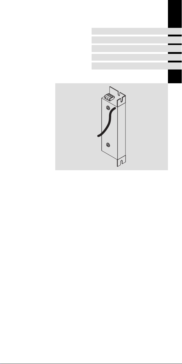
Funk-Entstörfilter
RFI filter
Filtre antiparasite
Page 2
1 Vorwort und Allgemeines
0Abb.0Tab. 0
1 Vorwortund Allgemeines
Lesen Sie zuerst diese Anleitung und die Dokumentation zum Grundgerät,
bevor Sie mit den Arbeiten beginnen!
Beachten Sie die enthaltenen Sicherheitshinweise.
Line
0
Load
0
1
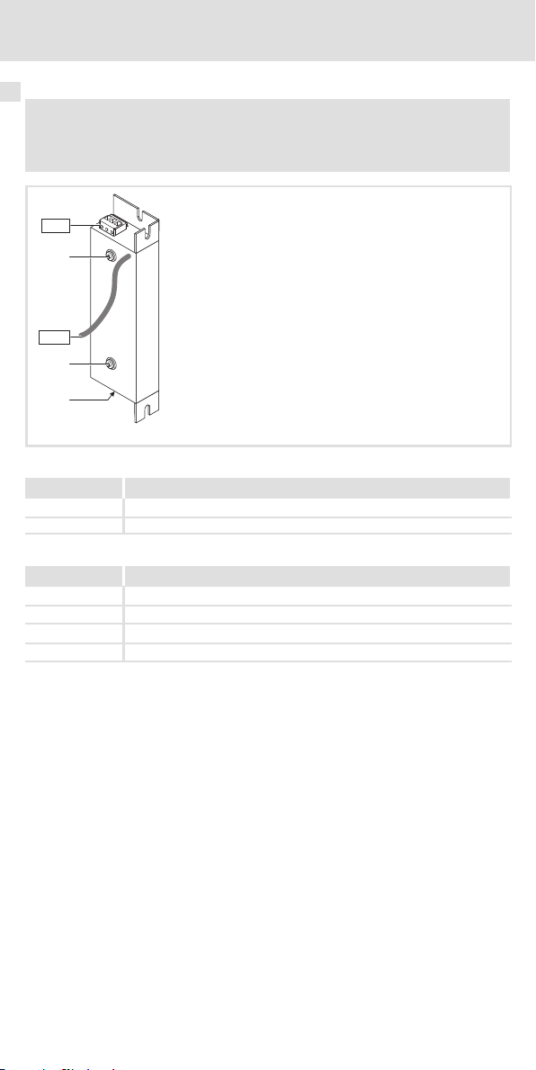
Lieferumfang
Anz. Beschreibung
1 Filter
1 Montageanleitung
Elemente am Filter
Pos. Beschreibung
Line Netzanschluss L1/N/PE oder L1/L2/L3/PE
Load Anschlussleitungen zum Antriebsregler L1’/N’/PE’ oder L1’/L2’/L3’/PE’
Informationen zur Gültigkeit
Diese Anleitung ist gültig für
ƒ Funk-Entstörfilter E82ZZxxxxxB200
ƒ Funk-Entstörfilter E82ZZxxxxxB210
ƒ Funk-Entstörfilter E82ZZxxxxxB220
Befestigungsschrauben Grundgerät
Typenschild
E82ZZ001
2
EDK82ZZ113 DE/EN/FR 2.1
Page 3
Identifikation
L
xxxxxxxxxxxxxxxx
Art.-Nr. / Part No.:
Typ / Type:
xxxxxxxxxxxxxxxxxxxxxx
xxxxxxxxxxxxxxxxxxxxxxxxxxxxxxxxxxxxxxxx
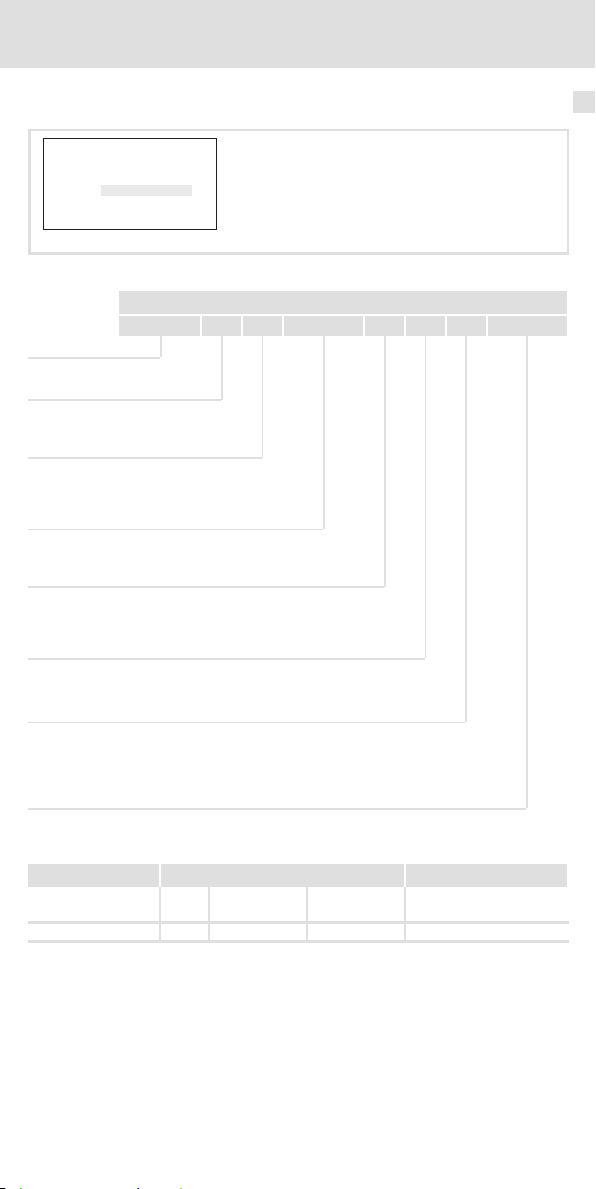
Abb. 1 Typenschild
xxxxxx
E82ZZ37112B200
Vorwort und Allgemeines 1
E82ZZ005
Typenschlüssel
E82 Z Z xxx 3 x B xxx
Produktreihe
Zubehör
Filtertyp
Z = Funk-Entstörfilter
Leistung
z. B. 752 = 75 x 102W = 7,5 kW
z. B. 113 = 11 x 103W=11kW
Anzahl Phasen
3=3Phasen
Spannungsklasse
2 = 230/240 V
4 = 400/500 V
Gerätegeneration
Filter-Variante
200 = SD (Short Distance)
210 = LD (Long Distance)
220=LL(LowLeakage)
c
Dokumenthistorie
Materialnummer Version Beschreibung
.=ik 2.1 07/2010 TD00 Neuauflage wegen Neuorga-
13216221 1.0 09/2007 TD29 Erstausgabe
nisation des Unternehmens
Tipp!
Aktuelle Dokumentationen und Software-Updates zu Lenze Produkten finden
Sie im Internet jeweils im Bereich ”Services & Downloads” unter
http://www.Lenze.com
EDK82ZZ113 DE/EN/FR 2.1
3
Page 4
1 Vorwort und Allgemeines
Einsetzbarkeit
Die Verwendung dieser Filter ist zulässig mit Antriebsreglern der Reihe 8200 vector im Leistungsbereich 0,25 ... 11 kW gemäß nachfolgender Zuordnung.
Zuordnung Filter – Grundgerät
230/240-V-Netz, 1/N/PE:
Funk-Entstörfilter-Typ Antriebsregler-Typ
E82ZZ37112B200
E82ZZ37112B210
E82ZZ37112B220
E82ZZ75112B200
E82ZZ75112B210
E82ZZ75112B220 E82xV551K2C2xx
E82ZZ22212B200
E82ZZ22212B210
230/240-V-Netz, 3/PE:
Funk-Entstörfilter-Typ Antriebsregler-Typ
E82ZZ75132B2x0
E82ZZ22232B2x0
E82ZZ40232B2x0
E82ZZ75232B2x0
400/500-V-Netz, 3/PE:
Funk-Entstörfilter-Typ Antriebsregler-Typ
E82ZZ75134B2x0
E82ZZ22234B2x0
E82ZZ55234B2x0
E82ZZ11334B2x0
E82xV251K2C2xx
E82xV371K2C2xx
E82xV551K2C2xx
E82xV751K2C2xx
E82xV152K2C2xx
E82xV222K2C2xx
E82xV551K2C2xx
E82xV751K2C2xx
E82xV152K2C2xx
E82xV222K2C2xx
E82xV302K2C2xx
E82xV402K2C2xx
E82xV552K2C2xx
E82xV752K2C2xx
E82xV551K4C2xx
E82xV751K4C2xx
E82xV152K4C2xx
E82xV222K4C2xx
E82xV302K4C2xx
E82xV402K4C2xx
E82xV552K4C2xx
E82xV752K4C2xx
E82xV113K4C2xx
4
EDK82ZZ113 DE/EN/FR 2.1
Page 5
Sicherheitshinweise
Verwendete Hinweise
2 Sicherheitshinweise
Verwendete Hinweise
Um auf Gefahren und wichtige Informationen hinzuweisen, werden in dieser Dokumentation folgende Piktogramme und Signalwörter verwendet:
Sicherheitshinweise
Aufbau der Sicherheitshinweise:
Gefahr!
(kennzeichnet die Art und die Schwere der Gefahr)
Hinweistext
(beschreibt die Gefahr und gibt Hinweise, wie sie vermieden werden kann)
Piktogramm und Signalwort Bedeutung
Gefahr von Personenschäden durch gefährliche elektrische Spannung
Gefahr!
Gefahr!
Stop!
Anwendungshinweise
Piktogramm und Signalwort Bedeutung
Hinweis auf eine unmittelbar drohende Gefahr, die den
Tod oder schwere Verletzungen zur Folge haben kann,
wenn nicht die entsprechenden Maßnahmen getroffen
werden.
Gefahr von Personenschäden durch eine allgemeine Gefahrenquelle
Hinweis auf eine unmittelbar drohende Gefahr, die den
Tod oder schwere Verletzungen zur Folge haben kann,
wenn nicht die entsprechenden Maßnahmen getroffen
werden.
Gefahr von Sachschäden
Hinweis auf eine mögliche Gefahr, die Sachschäden zur
Folge haben kann, wenn nicht die entsprechenden Maßnahmen getroffen werden.
2
Hinweis!
Tipp!
EDK82ZZ113 DE/EN/FR 2.1
Wichtiger Hinweis für die störungsfreie Funktion
Nützlicher Tipp für die einfache Handhabung
Verweis auf andere Dokumentation
5
Page 6

2 Sicherheitshinweise
Restgefahren
Restgefahren
Gefahr!
Gefährliche elektrischeSpannung
Alle Leistungsanschlüsseführen bis zu 3 Minuten nach Netz-Ausschalten
gefährliche elektrische Spannung.
Mögliche Folgen:
ƒ Tod oder schwere Verletzungen beim Berühren der Leistungsanschlüsse.
Schutzmaßnahmen:
ƒ Vor Arbeiten an den LeistungsanschlüssenNetz abschalten und
mindestens3 Minuten warten.
ƒ Prüfen, ob alle Leistungsanschlüssespannungsfrei sind.
Gefahr!
Gefährliche elektrischeSpannung
Bei den Filter-Varianten 200 und 210 ist der Ableitstrom gegen Erde (PE)
>3,5mAACbzw.>10mADC.
Mögliche Folgen:
ƒ Tod oder schwere Verletzungen beim Berühren des Gerätes im Fehlerfall.
Schutzmaßnahmen:
ƒ D ie in der EN 61800-5-1 geforderten Maßnahmen umsetzen.
Insbesondere:
– Festinstallation
– PE-Anschlussnormgerechtausführen (PE-Leiterdurchmesser≥ 10 mm
oder PE-Leiter doppelt auflegen)
2
Stop!
Kein Geräteschutz gegen zu hohe Netzspannung
Der Netzeingang ist intern nicht abgesichert.
Mögliche Folgen:
ƒ Zerstörung des Gerätes bei zu hoher Netzspannung.
Schutzmaßnahmen:
ƒ Beachten Sie die maximal zulässige Netzspannung.
ƒ Sichern Sie das Gerät netzseitig fachgerecht gegen Netzschwankungen
und Spannungsspitzen ab.
Warnings!
Conditions of Acceptability:
ƒ The filter series E82ZZ shall be mounted into an enclosure providing
adequate spacings.
ƒ The terminals have not been evaluated for field wiring connection.
ƒ These devices are only intended to be used with this manufacturer’s
Inverters Type 8200 Vector, having a controlled overvoltage means.
6
EDK82ZZ113 DE/EN/FR 2.1
Page 7
Allgemeine Daten und Einsatzbedingungen
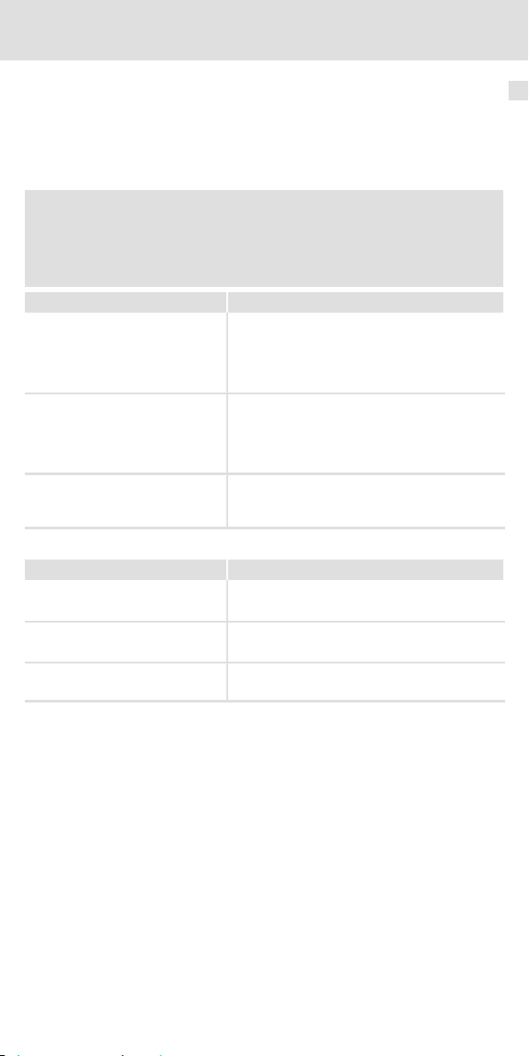
Technische Daten
3 TechnischeDaten
Allgemeine Daten und Einsatzbedingungen
Normen
Approbation UL UL 508C, Component Power Conversion Equipment - Accesso-
Angaben zu Netzen
Netzformen
mit geerdetem Y-Punkt (TT-/TN-Netze)
IT-Netze
230 V Anweisungen über besondere Maßnahmen in der Dokumen-
400 V Max. Netzspannung 400 V!
Schutz
Schutzart
Isolationsfestigkeit EN 61800-5-1 ÜberspannungskategorieIII
Ableitstrom EN 61800-5-1
E82ZZ...B200
E82ZZ...B210
E82ZZ...B220 <3,5mA
EN 60529
NEMA 250 Berührschutz nach Typ 1
Umweltbedingungen
Temperatur
Lagerung
Transport -25 ... +70 °C
Betrieb -10 ... +55 °C
Aufstellhöhe 0 ... 4000 m üNN
Verschmutzung EN 61800-5-1 Verschmutzungsgrad 2
Rüttelfestigkeit EN50178, IEC61800-5-1,
Germanischer Loyd, allgemeine Bedingungen
ries (File No. E132659) for USA and Canada
uneingeschränkte Nutzung
tation zum Grundgerät beachten!
Anweisungen über besondere Maßnahmen in der Dokumentation zum Grundgerät beachten!
IP 20
Reduzierung ab 2000 m: Überspannungskategorie II
>3,5mA Bestimmungen und
-25 ... +60 °C
Stromreduzierung von +40 ... +55 °C: 2.5 %/°C
1000 ... 4000 m üNN: Stromreduzierung 5 %/1000 m
Beschleunigungsfest bis 0.7 g
nicht im Anschlussbereich
der Klemmen
Sicherheitshinweise
beachten!
3
Montagebedingungen
Montageort im Schaltschrank
Montageposition Standard: zwischen Montageplatte und Grundgerät
Einbaulage senkrecht, Anschlüsse oben
EDK82ZZ113 DE/EN/FR 2.1
Variante: links neben dem Grundgerät
7
Page 8
3 Technische Daten
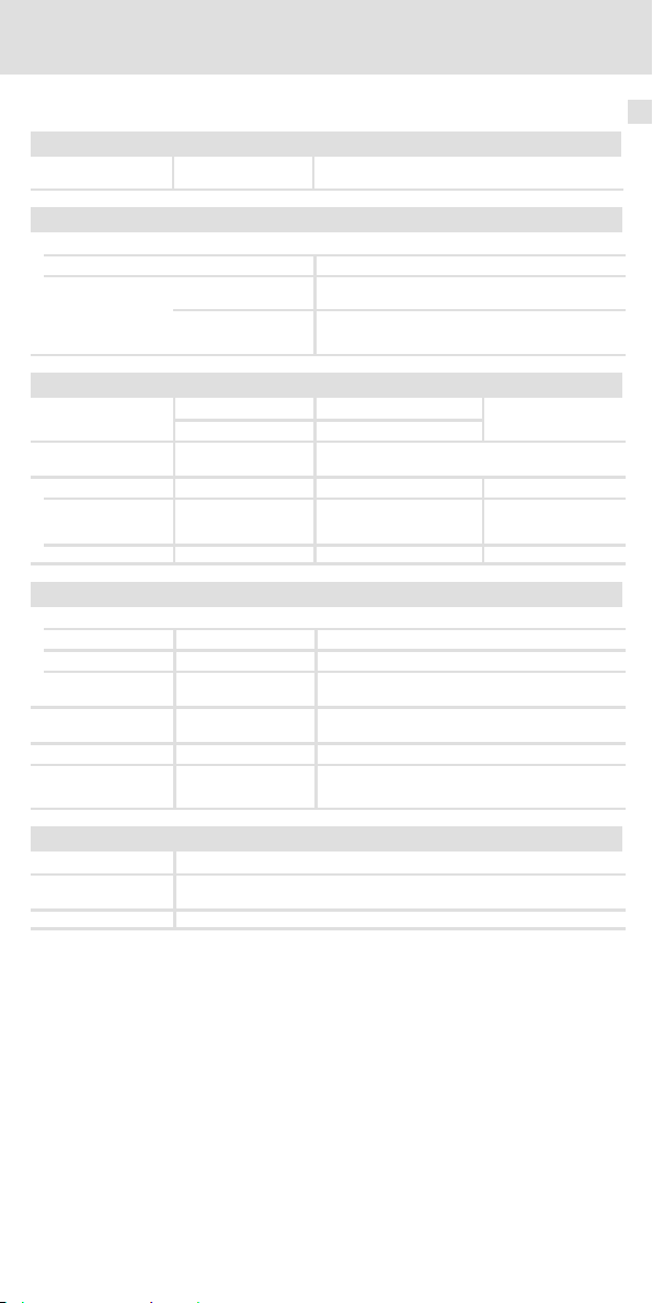
Bemessungsdaten
Bemessungsdaten
Grundlage der Daten
Spannung
Netz
1/N/PE AC 230/240 180-0%...264+0% 45 ... 65
3/PE AC 230/240 180-0%...264+0% 45 ... 65
3/PE AC 400 320-0%...440+0% 45 ... 65
3/PE AC 500 400-0%...550+0% 45 ... 65
U[V]
Spannungsbereich
U[V]
Frequenzbereich
f[Hz]
Typ Phasenzahl Spannung
[V]
Freq.
[Hz]
Strom
[A]
c max. +40° C c max. +55° C
E82ZZ...
37112B...
75112B... 50/60 9.5 5.9
22212B... 50/60 18.0 11.2
75132B...
22232B... 50/60 12.5 7.8
40232B... 50/60 22.0 13.7
75232B... 50/60 30.0 18.7
75134B...
22234B... 50/60 7.3/7.3 4.5/4.5
55234B... 50/60 16.8/16.8 10.5/10.5
11334B... 50/60 21.0/21.0 13.1/13.1
1 230/240
3 230/240
3 400/500
50/60 5.0 3.1
50/60 5.5 3.4
50/60 3.4/3.4 2.1/2.1
c Temperatur im Schaltschrank
Typ
E82ZZ...
37112B... 10 - -
75112B... 15 - -
22212B... 20 - -
75132B... 15 - -
22232B... 20 - -
40232B... 35 - -
75232B... 40 - -
75134B... 15 - -
22234B... 20 - -
55234B... 35 - -
11334B... 40 - -
Verlustleistung Induktivität Spannungsabfall
Pv [W] L[mH]
ΔU[V]
Strom
[A]
8
EDK82ZZ113 DE/EN/FR 2.1
Page 9
Technische Daten
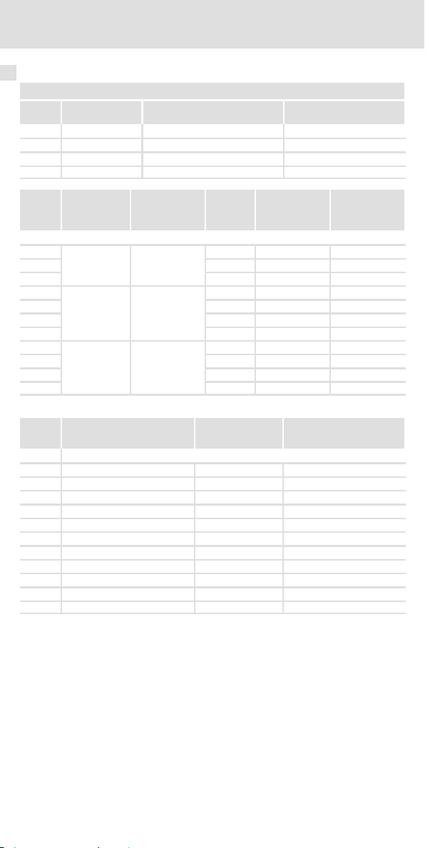
Mechanische Daten
Mechanische Daten
Leistungsbereich 0,25 ... 2,2 kW
Abb. 2 Abmessungen Filter
Alle Maße in Millimeter.
Typ
b b1 b2 b3 e m l
E82ZZ37112... 217 172 135 23.5 30 197 120 0.5
E82ZZ75112... 277 232 195 25 40 247 130 0.8
E82ZZ22212... 337 292 255 24 40 317 130 0.9
E82ZZ75132... 277 232 195 26 40 40 130 0.8
E82ZZ22232... 337 292 255 24 40 40 130 0.8
E82ZZ75134... 277 232 195 26 40 247 130 0.8
E82ZZ22234... 337 292 255 24 40 317 130 0.9
Maße Masse
[mm]
3
E82ZZ002
[kg]
EDK82ZZ113 DE/EN/FR 2.1
9
Page 10
3 Technische Daten
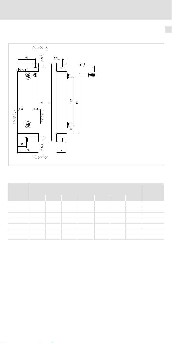
Mechanische Daten
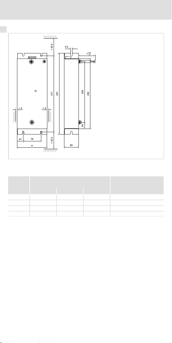
Leistungsbereich 3 ... 11 kW
Abb. 3 Abmessungen Filter
Alle Maße in Millimeter.
Typ
a a1 l
E82ZZ40232... 100 12.5 150 1.7
E82ZZ75232... 125 25 170 2.1
E82ZZ55234... 100 12.5 150 1.7
E82ZZ11334... 125 25 170 2.1
Maße Masse
[mm]
E82ZZ003
[kg]
10
EDK82ZZ113 DE/EN/FR 2.1
Page 11

Mechanische Installation
Wichtige Hinweise
4 MechanischeInstallation
Wichtige Hinweise
ƒ Der Montageort muss den in den Technischen Daten genannten Einsatzbedingungen
immer entsprechen (7). Ggf. zusätzliche Maßnahmen ergreifen.
ƒ Die Montageplatte des Schaltschranks muss folgende Eigenschaften aufweisen:
– elektrisch leitfähig
–lackfrei
ƒ Die mechanischen Verbindungen müssen immer gewährleistet sein.
ƒ Bei Betrieb des Funk-Entstörfilters E82ZZ75232B2x0 oder E82ZZ11334B2x0 mit
Netzdrossel ELN3-0088H035/ELN3-0150H024 mindestens 220 mm Abstand
zwischen Funk-Entstörfilter und Netzdrossel einhalten.
ƒ Grundgeräte des Typs E82EV... (Einbaugeräte) können sowohl auf das Filter montiert
werden (Standard-Montage) als auch rechts neben dem Filter (Montage-Variante).
Grundgeräte des Typs E82DV... (Durchstoßtechnik) undE82CV...(ColdPlate) könnennur
rechts neben dem Filter montiert werden (Montage-Variante).
4
EDK82ZZ113 DE/EN/FR 2.1
11
Page 12
4 Mechanische Installation
Montageschritte
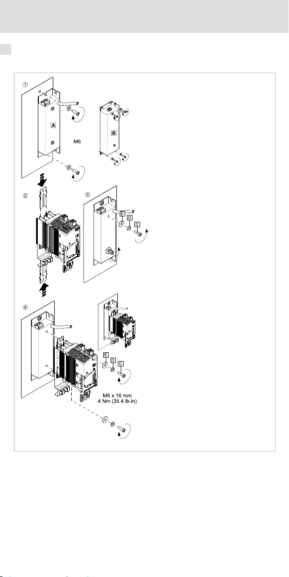
Montageschritte
Standard-Montage
Abb. 4 Montage des Filters
Filter im Leistungsbereich 0,25 ... 2,2 kW
Filter im Leistungsbereich 3 ... 11 kW
12
E82ZZ006
EDK82ZZ113 DE/EN/FR 2.1
Page 13
Mechanische Installation
Montageschritte
So montieren Sie das Filter:
1. Zwei bzw. vier M6-Befestigungsbohrungen (/) auf der Montageplatte vorbereiten
und das Filter mit 2 bzw. 4 Schrauben und Unterlegscheiben montieren.
– Abmessungen und Einbaufreiräume beachten (9).
2. Befestigungsschienen auf den Kühlkörper des Grundgerätes schieben.
3. Die obere Schraube einschließlich Federringe und Unterlegscheiben entfernen.
DieuntereSchraube so weit herausdrehen, dass sie noch sicher im Gewinde steckt.
4. Grundgerät mit Schrauben , Federringe und Unterlegscheiben auf das Filter
montieren.
– Anzugsmoment beachten.
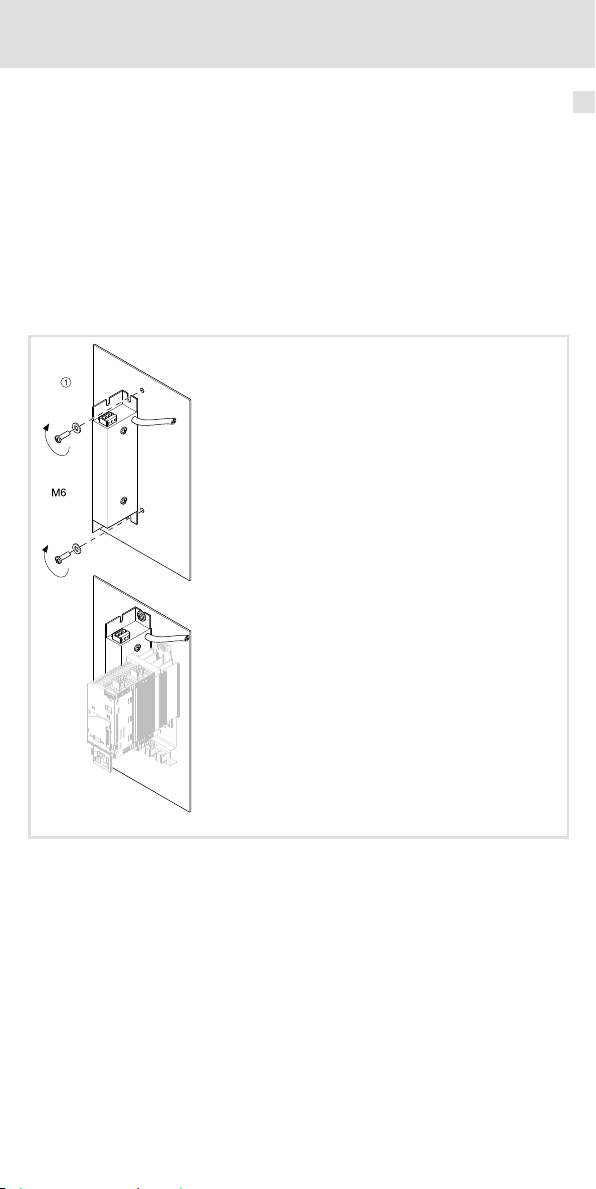
Montage-Variante
4
E82ZZ007
Abb. 5 Montage des Filters
So montieren Sie das Filter:
1. Zwei Befestigungsbohrungen M6 auf der Montageplatte vorbereiten und das Filter
mit 2 Schrauben und Unterlegscheiben montieren.
Anschließend kann das Grundgerätrechts neben dem Filter montiert werden ( Doku-
mentation zum Grundgerät).
EDK82ZZ113 DE/EN/FR 2.1
13
Page 14
5 Elektrische Installation
Wichtige Hinweise
5 ElektrischeInstallation
Wichtige Hinweise
ƒ Die Installation muss
– den in den Technischen Daten genannten Einsatzbedingungen immer
entsprechen (7).
– nach EN 60204-1 ausgeführt werden.
ƒ Bei der Auswahl des Leitungstyps beachten:
– Die verwendeten Leitungen müssen den geforderten Approbationen am
Einsatzort entsprechen (z. B. VDE, UL usw.).
– Absicherung und Leitungsquerschnitte gemäß den Vorgaben in der
Dokumentation zum Grundgerät bemessen.
ƒ Beim Verlegen der PE-Leitung beachten:
– Der PE-Anschluss muss nach EN 61800-5-1 ausgeführt werden.
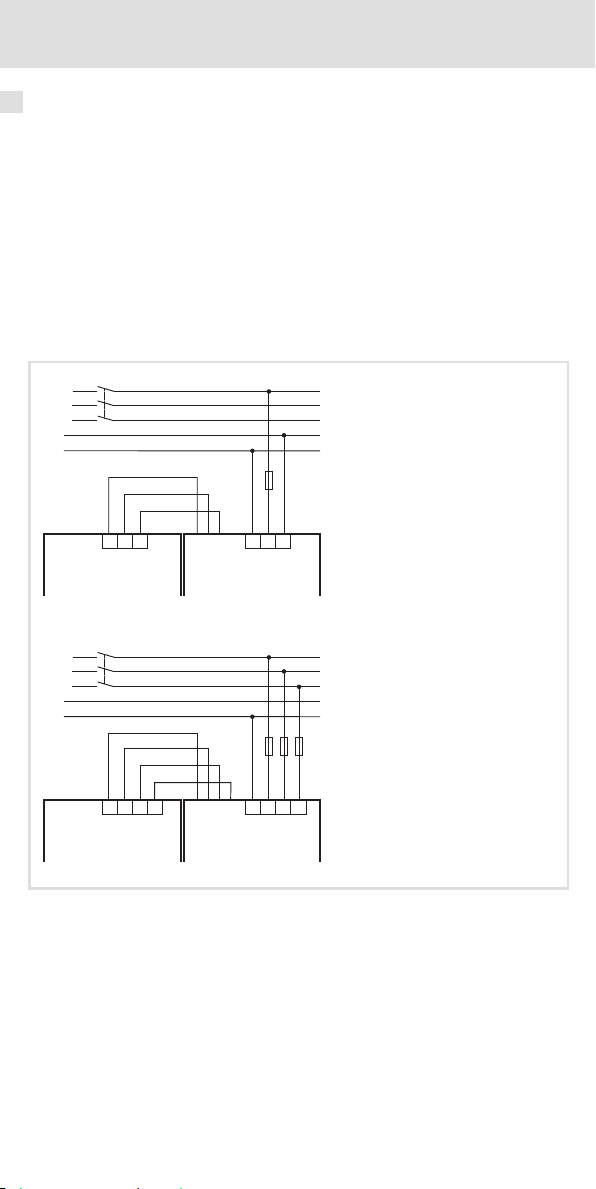
Anschlussplan
K1
L1
L2
L3
N
PE
GN/YE
BK
BU
F
L1
N
PE
8200 vector
K1
L1
L2
L3
N
PE
PE
L1
L2
8200 vector
Load
GN/YE
BK
BK
BK
Load
L1
PE
Line
E82ZZxxx Bxxx1x
PE
L1
Line
E82ZZxxx xBxxx3
N
F
L3L3
L2
E82ZZ004
14
EDK82ZZ113 DE/EN/FR 2.1
Page 15

Anschlussdaten
Klemmen ”Line”
Elektrische Installation
Anschlussdaten
5
E82ZZ37112...
E82ZZ75112...
E82ZZ22212...
E82ZZ75132...
E82ZZ22232...
E82ZZ40232...
E82ZZ75232...
E82ZZ75134...
E82ZZ22234...
E82ZZ55234...
E82ZZ11334...
Montageschritte
[mm2] [AWG]
0.2 ... 4 24 ... 10
[Nm]
[lb-in]
0.5 ... 0.6
4.4 ... 5.3
E82ZZ008
So schließen Sie das Filter an:
1. Schaltschrank spannungsfrei schalten und gegen Wiedereinschalten sichern.
2. Filter-Ausgangsleitungen ”Load” an Klemme X1.1 des Grundgerätes anschließen.
– Dokumentation zum Grundgerät beachten!
3. Netzleitungen an Klemme ”Line” anschließen.
– Anzugsmoment beachten!
EDK82ZZ113 DE/EN/FR 2.1
15
Page 16

1 Preface and general information
0Fig.0Tab. 0
1 Prefaceand generalinformation
Please read these instructions and the documentation of the standard device
before you start working!
Observe the safety instructions given therein!
Line
0
Load
0
1
Scope of supply
Qty. Description
1 Filter
1 Mounting Instructions
Elements on the filter
Pos. Description
Line Mains connection for L1/N/PE or L1/L2/L3/PE
Load Connecting cables to controller L1’/N’/PE’ or L1’/L2’/L3’/PE’
Validity information
These instructions are valid for
ƒ E82ZZxxxxxB200RFI filters
ƒ E82ZZxxxxxB210RFI filters
ƒ E82ZZxxxxxB220RFI filters
Fixing screws for standard device
Nameplate
E82ZZ001
16
EDK82ZZ113 DE/EN/FR 2.1
Page 17

Identification
L
xxxxxxxxxxxxxxxx
Art.-Nr. / Part No.:
Typ / Type:
xxxxxxxxxxxxxxxxxxxxxx
xxxxxxxxxxxxxxxxxxxxxxxxxxxxxxxxxxxxxxxx
Fig. 1 Nameplate
xxxxxx
E82ZZ37112B200
Preface and general information 1
E82ZZ005
Type code
E82 Z Z xxx 3 x B xxx
Product range
Accessories
Filter type
Z = RFI filter
Power
e.g.752=75x102W = 7.5 kW
e.g.113=11x103W=11kW
Number of phases
3=3phases
Voltage class
2 = 230/240 V
4 = 400/500 V
Generation
Filter variant
200 = SD (Short Distance)
210 = LD (Long Distance)
220=LL(LowLeakage)
c
Document history
Material number Version Description
.=ik 2.1 07/2010 TD00 New edition due to
13216221 1.0 09/2007 TD29 First edition
reorganisation of the
company
Tip!
Current documentation and software updates concerning Lenze products can
be found on the Internet in the ”Services & Downloads” area under
http://www.Lenze.com
EDK82ZZ113 DE/EN/FR 2.1
17
Page 18

1 Preface and general information
Application range
The filters can be used together with 8200 vector controllers in the power range from 0.25
... 11 kW according to the following assignment:
Assignment of filters to standard devices
230/240-V mains, 1/N/PE:
RFI filter type Controller type
E82ZZ37112B200
E82ZZ37112B210
E82ZZ37112B220
E82ZZ75112B200
E82ZZ75112B210
E82ZZ75112B220 E82xV551K2C2xx
E82ZZ22212B200
E82ZZ22212B210
230/240-V mains, 3/PE:
RFI filter type Controller type
E82ZZ75132B2x0
E82ZZ22232B2x0
E82ZZ40232B2x0
E82ZZ75232B2x0
400/500-V mains, 3/PE:
RFI filter type Controller type
E82ZZ75134B2x0
E82ZZ22234B2x0
E82ZZ55234B2x0
E82ZZ11334B2x0
E82xV251K2C2xx
E82xV371K2C2xx
E82xV551K2C2xx
E82xV751K2C2xx
E82xV152K2C2xx
E82xV222K2C2xx
E82xV551K2C2xx
E82xV751K2C2xx
E82xV152K2C2xx
E82xV222K2C2xx
E82xV302K2C2xx
E82xV402K2C2xx
E82xV552K2C2xx
E82xV752K2C2xx
E82xV551K4C2xx
E82xV751K4C2xx
E82xV152K4C2xx
E82xV222K4C2xx
E82xV302K4C2xx
E82xV402K4C2xx
E82xV552K4C2xx
E82xV752K4C2xx
E82xV113K4C2xx
18
EDK82ZZ113 DE/EN/FR 2.1
Page 19

Safety instructions
Notes used
2 Safetyins tructions
Notes used
The following pictographs and signal words are used in this documentation to indicate
dangers and important information:
Safety instructions
Structure of safety instructions:
Danger!
(characterises the type and severity of danger)
Note
(describes the danger and gives information about how to prevent dangerous
situations)
Pictograph and signal word Meaning
Danger of personal injury through dangerous electrical
voltage.
Danger!
Danger!
Stop!
Application notes
Pictograph and signal word Meaning
Reference to an imminent danger that may result in
death or serious personal injury if the corresponding
measures are not taken.
Danger of personal injury through a general source of
danger.
Reference to an imminent danger that may result in
death or serious personal injury if the corresponding
measures are not taken.
Danger of property damage.
Reference to a possible danger that may result in
property damage if the corresponding measures are not
taken.
2
Note!
Tip!
EDK82ZZ113 DE/EN/FR 2.1
Important note to ensure troublefree operation
Useful tip for simple handling
Reference to another documentation
19
Page 20

2 Safety instructions
Residual hazards
Residual hazards
Danger!
Dangerous electrical voltage
All power terminals remain live for up to three minutes after mains
disconnection.
Possible consequences:
ƒ Death or severe injuries when touching the power terminals.
Protective measures:
ƒ Switch off the power supply and wait for at least three minutes before
working on the power terminals.
ƒ Make sure that all power terminals are deenergised.
Danger!
Dangerous voltage
With the filter variants 200 and 210, the leakage current to earth (PE) is
>3.5mAACor>10mADC.
Possible consequences:
ƒ Death or severe injuries when touching the device in case of a fault.
Protective measures:
ƒ Take the measures specified in EN 61800-5-1. In particular:
– Fixed installation
– PE connection according to standard (PE conductor diameter ≥ 10 mm
or connect PE conductor twice)
2
Stop!
No device protection if the mains voltage is too high
The mains input is not internally fused.
Possible consequences:
ƒ Destruction of the device if the mains voltage is too high.
Protective measures:
ƒ Observe the maximally permissible mains voltage.
ƒ Fuse the device correctly on the supply side against mains fluctuations and
voltage peaks.
Warnings!
Conditions of acceptability:
ƒ The E82ZZ filters must be mounted into an enclosure providing adequate
spacings.
ƒ The terminals have not been evaluated for field wiring connection.
ƒ These devices are only intended for use with Lenze 8200 vector inverters
with a controlled overvoltage means.
20
EDK82ZZ113 DE/EN/FR 2.1
Page 21

General data and operating conditions
Technical data
3 Technicaldata
General data and operating conditions
Standards
Approval UL UL 508C, Component Power Conversion Equipment -
Mains data
Mains types
With grounded neutral (TT /TN systems)
IT systems
230 V Observe instructions for special measures in the
400 V Max. mains voltage 400 V!
Protection
Type of protection
Insulation resistance EN 61800-5-1 Overvoltage category III
Leakage current EN 61800-5-1
E82ZZ...B200
E82ZZ...B210
E82ZZ...B220 <3.5mA
EN 60529
NEMA 250 Protection against contact to
Ambient conditions
Temperature
Storage
Transport -25 ... +70 °C
Operation -10 ... +55 °C
Site altitude 0 ... 4000 m amsl
Pollution EN61800-5-1 Pollution degree 2
Vibration resistance EN 50178, IEC 61800-5-1,
Germanischer Lloyd,
general conditions
Accessories (file no. E132659) for the US and Canada
Operation permitted without restrictions
documentation for the basic device!
Observe instructions for special measures in the
documentation for the basic device!
IP 20
type 1
> 2000 m: Overvoltage category II
>3.5mA Observe regulations and
-25 ... +60 °C
Current derating from +40 to +55 °C: 2.5 %/°C
1000 ... 4000 m amsl: Current derating by 5 %/1000 m
Acceleration-resistant up to 0.7 g
Not in the wire range of
the terminals
safety instructions!
3
Mounting conditions
Mounting location In the control cabinet
Position Standard: between mounting plate and basic device
Mounting position Vertical, connections on top
EDK82ZZ113 DE/EN/FR 2.1
Variant: to the left of the basic device
21
Page 22

3 Technical data
Rated data
Rated data
Data basis
Voltage
Mains
1/N/PE AC 230/240 180-0%...264+0% 45 ... 65
3/PE AC 230/240 180-0%...264+0% 45 ... 65
3/PE AC 400 320-0%...440+0% 45 ... 65
3/PE AC 500 400-0%...550+0% 45 ... 65
U[V]
Voltage range
U[V]
Frequency range
f[Hz]
Type Number of phases Voltage
[V]
Freq.
[Hz]
Current
[A]
c max. +40° C c max. +55° C
E82ZZ...
37112B...
75112B... 50/60 9.5 5.9
22212B... 50/60 18.0 11.2
75132B...
22232B... 50/60 12.5 7.8
40232B... 50/60 22.0 13.7
75232B... 50/60 30.0 18.7
75134B...
22234B... 50/60 7.3/7.3 4.5/4.5
55234B... 50/60 16.8/16.8 10.5/10.5
11334B... 50/60 21.0/21.0 13.1/13.1
1 230/240
3 230/240
3 400/500
50/60 5.0 3.1
50/60 5.5 3.4
50/60 3.4/3.4 2.1/2.1
c Temperature in the control cabinet
Type
E82ZZ...
37112B... 10 - -
75112B... 15 - -
22212B... 20 - -
75132B... 15 - -
22232B... 20 - -
40232B... 35 - -
75232B... 40 - -
75134B... 15 - -
22234B... 20 - -
55234B... 35 - -
11334B... 40 - -
Power loss Inductance Voltage drop
P
[W] L[mH]
loss
ΔU[V]
Current
[A]
22
EDK82ZZ113 DE/EN/FR 2.1
Page 23

Technical data
Mechanical data
Mechanical data
Power range from 0.25 ... 2.2 kW
Fig. 2 Filterdimensions
All dimensions in millimetres.
Type
b b1 b2 b3 e m l
E82ZZ37112... 217 172 135 23.5 30 197 120 0.5
E82ZZ75112... 277 232 195 25 40 247 130 0.8
E82ZZ22212... 337 292 255 24 40 317 130 0.9
E82ZZ75132... 277 232 195 26 40 40 130 0.8
E82ZZ22232... 337 292 255 24 40 40 130 0.8
E82ZZ75134... 277 232 195 26 40 247 130 0.8
E82ZZ22234... 337 292 255 24 40 317 130 0.9
Dimensions Mass
Dimensions [mm]
3
E82ZZ002
[kg]
EDK82ZZ113 DE/EN/FR 2.1
23
Page 24

3 Technical data
Mechanical data
Power range from 3 ... 11 kW
Fig. 3 Filterdimensions
All dimensions in millimetres.
Type
a a1 l
E82ZZ40232... 100 12.5 150 1.7
E82ZZ75232... 125 25 170 2.1
E82ZZ55234... 100 12.5 150 1.7
E82ZZ11334... 125 25 170 2.1
Dimensions Mass
Dimensions [mm]
E82ZZ003
[kg]
24
EDK82ZZ113 DE/EN/FR 2.1
Page 25

Mechanical installation
Important notes
4 Mechanicalinstallation
Important notes
ƒ The mounting location must always fulfill the operating conditions specified in the
Technical data. (21). If necessary, take additional measures.
ƒ The mounting plate of the control cabinet must be:
– electrically conductive
– free of lacquer
ƒ The mechanical connections must always be ensured.
ƒ When E82ZZ75232B2x0 or E82ZZ11334B2x0 RFI filters are used together with mains
chokes ELN3-0088H035/ELN3-0150H024, keep a distance of at least 220 mm
between RFI filter and mains choke.
ƒ Basic devices of type E82EV... (built-in units) can be mounted onto the filter (standard
mounting) or to the right of the filter (mounting variant).
Basic devices of types E82DV... (push-through technique) and E82CV... (cold plate) can
only be mounted to the right of the filter (mounting variant).
4
EDK82ZZ113 DE/EN/FR 2.1
25
Page 26

4 Mechanical installation
Mounting steps
Mounting steps
Standard mounting
Fig. 4 Filterassembly
Filter in the power range from 0.25 ... 2.2 kW
Filter in the power range from 3 ... 11 kW
26
E82ZZ006
EDK82ZZ113 DE/EN/FR 2.1
Page 27

Mechanical installation
Mounting steps
How to mount the filter:
1. Drill two or four M6 fixing holes (/) in the mounting plate and mount the filter
using 2 or 4 screws and washers.
– Observe dimensions and mounting clearances (23).
2. Push the fixing rails onto the heatsink of the basic device.
3. Remove the upper screw including lock washers and washers .Unscrewthe
lower screw as far that it is still secure in the thread.
4. Mount the basic device onto the filter using the screws ,lockwashers and
washers .
– Observe tightening torque.
Mounting variant
4
E82ZZ007
Fig. 5 Filterassembly
How to mount the filter:
1. Drill two M6 fixing holes in the mounting plate and mount the filter using 2 screws
and washers.
After this, the basic device can be mounted to the right of the filter ( documentation
for the basic device).
EDK82ZZ113 DE/EN/FR 2.1
27
Page 28

5 Electrical installation
Important notes
5 Electricalinstallation
Important notes
ƒ Installation must
– always be in accordance with the operating conditions specified in the Technical
data (21).
– be carried out to EN 60204-1.
ƒ Please observe the following when selecting the cable type:
– The cables used must comply with the approvals required for the application (e. g.
VDE, UL etc.).
– Fuses and cable cross-sections must be dimensioned in accordance with the
specifications in the documentation for the basic device.
ƒ Please observe the following when laying the PE cable:
– The PE connection must comply with EN 61800-5-1.
Connection plan
K1
L1
L2
L3
N
PE
GN/YE
BK
BU
F
L1
N
PE
8200 vector
K1
L1
L2
L3
N
PE
PE
L1
L2
8200 vector
Load
GN/YE
BK
BK
BK
Load
L1
PE
Line
E82ZZxxx Bxxx1x
PE
L1
Line
E82ZZxxx xBxxx3
N
F
L3L3
L2
E82ZZ004
28
EDK82ZZ113 DE/EN/FR 2.1
Page 29

Connection data
Terminals ”line”
Electrical installation
Connection data
5
E82ZZ37112...
E82ZZ75112...
E82ZZ22212...
E82ZZ75132...
E82ZZ22232...
E82ZZ40232...
E82ZZ75232...
E82ZZ75134...
E82ZZ22234...
E82ZZ55234...
E82ZZ11334...
Mounting steps
[mm2] [AWG]
0.2 ... 4 24 ... 10
[Nm]
[lb-in]
0.5 ... 0.6
4.4 ... 5.3
How to connect the filter:
1. Disconnect the control cabinet from the mains and protect against power-on.
2. Connect the ”Load” filter output cables to terminal X1.1 of the basic device.
– Observe the documentation for the basic device!
3. Connect the mains cables to terminal ”Line”.
– Observe tightening torque!
EDK82ZZ113 DE/EN/FR 2.1
E82ZZ008
29
Page 30

1 Avant-propos et généralités
0Fig.0Tab. 0
1 Avant-proposet généralités
Lire le présent fascicule et la documentation relative à l’appareil de base avant
toute manipulation de l’équipement !
Respecter les consignes de sécurité fournies.
Line
0
Load
0
1
Equipement livré
Nombre Description
1 Filtre
1 Instructions de montage
Eléments du filtre
Pos. Description
Line Raccordement sur réseau L1/N/PE ou L1/L2/L3/PE
Load Câbles de raccordement vers le variateur de vitesse L1’/N’/PE’ ou L1’/L2’/L3’/PE’
Informations relatives à la validité
Le présent document s’applique au produit suivant :
ƒ filtres antiparasites E82ZZxxxxxB200
ƒ filtres antiparasites E82ZZxxxxxB210
ƒ filtres antiparasites E82ZZxxxxxB220
Vis de fixation appareil de base
Plaque signalétique
E82ZZ001
30
EDK82ZZ113 DE/EN/FR 2.1
Page 31

Identification
L
xxxxxxxxxxxxxxxx
Art.-Nr. / Part No.:
Typ / Type:
xxxxxxxxxxxxxxxxxxxxxx
xxxxxxxxxxxxxxxxxxxxxxxxxxxxxxxxxxxxxxxx
Fig. 1 Plaquesignalétique
xxxxxx
E82ZZ37112B200
Avant-propos et généralités 1
E82ZZ005
Codification
des types
E82 Z Z xxx 3 x B xxx
Série
d’appareils
Accessoires
Type de filtre
Z = filtre antiparasite
Puissance
p. ex. 752 = 75 x 102W = 7,5 kW
p. ex. 113 = 11 x 103 W = 11 kW
Nombre de phases
3=3phases
Classe de tension
2 = 230/240 V
4 = 400/500 V
Génération d’appareils
Variante de filtre
200 = SD (Short Distance)
210 = LD (Long Distance)
220=LL(LowLeakage)
c
Historique du document
Numéro de document Version Description
.=ik 2.1 07/2010 TD00 Nouvelle édition en raison de
13216221 1.0 09/2007 TD29 Première édition
la nouvelle organisation de
l’entreprise
Conseil !
Les mises à jour de logiciels et les documentations récentes relatives aux
produits Lenze sont disponibles dans la zone ”Téléchargements” du site
Internet :
http://www.Lenze.com
EDK82ZZ113 DE/EN/FR 2.1
31
Page 32

1 Avant-propos et généralités
Utilisation
Ces filtres sont utilisables avec les variateurs de vitesse de la série 8200 vector dans la plage
de puissance 0,25 ... 11 kW selon les combinaisons ci-dessous.
Combinaisons filtre – appareil de base
Réseau 230/240 V, 1/N/PE :
Type de filtre antiparasite Type de variateur
E82ZZ37112B200
E82ZZ37112B210
E82ZZ37112B220
E82ZZ75112B200
E82ZZ75112B210
E82ZZ75112B220 E82xV551K2C2xx
E82ZZ22212B200
E82ZZ22212B210
Réseau 230/240 V, 3/PE :
Type de filtre antiparasite Type de variateur
E82ZZ75132B2x0
E82ZZ22232B2x0
E82ZZ40232B2x0
E82ZZ75232B2x0
Réseau 400/500 V, 3/PE :
Type de filtre antiparasite Type de variateur
E82ZZ75134B2x0
E82ZZ22234B2x0
E82ZZ55234B2x0
E82ZZ11334B2x0
E82xV251K2C2xx
E82xV371K2C2xx
E82xV551K2C2xx
E82xV751K2C2xx
E82xV152K2C2xx
E82xV222K2C2xx
E82xV551K2C2xx
E82xV751K2C2xx
E82xV152K2C2xx
E82xV222K2C2xx
E82xV302K2C2xx
E82xV402K2C2xx
E82xV552K2C2xx
E82xV752K2C2xx
E82xV551K4C2xx
E82xV751K4C2xx
E82xV152K4C2xx
E82xV222K4C2xx
E82xV302K4C2xx
E82xV402K4C2xx
E82xV552K4C2xx
E82xV752K4C2xx
E82xV113K4C2xx
32
EDK82ZZ113 DE/EN/FR 2.1
Page 33

Consignes de sécurité
Consignes utilisées
2 Consignesde sécurité
Consignes utilisées
Pour indiquer des risques et des informations importantes, la présente documentation
utilise les mots et symboles suivants :
Consignes de sécurité
Présentation des consignes de sécurité
Danger !
(Lepictogrammeindiqueletypederisque.)
Explication
(L’explication décrit le risque et les moyens de l’éviter.)
Pictogramme et mot associé Explication
Situation dangereuse pour les personnes en raison d’une
tension électrique élevée
Danger !
Danger !
Stop !
Consignes d’utilisation
Pictogramme et mot associé Explication
Indication d’un danger imminent qui peut avoir pour
conséquences des blessures mortelles ou très graves en
cas de non-respect des consignes de sécurité
correspondantes
Situation dangereuse pour les personnes en raison d’un
danger d’ordre général
Indication d’un danger imminent qui peut avoir pour
conséquences des blessures mortelles ou très graves en
cas de non-respect des consignes de sécurité
correspondantes
Risques de dégâts matériels
Indication d’un risque potentiel qui peut avoir pour
conséquences des dégâts matériels en cas de non-respect
des consignes de sécurité correspondantes
2
Remarque
importante !
Conseil !
EDK82ZZ113 DE/EN/FR 2.1
Remarque importante pour assurer un fonctionnement
correct
Conseil utile pour faciliter la mise en oeuvre
Référence à une autre documentation
33
Page 34

2 Consignes de sécurité
Dangers résiduels
Dangers résiduels
Danger !
Tension électrique dangereuse
Les raccordements de puissance sont encore sous tension jusqu’à 3 minutes
après la coupure réseau.
Risques encourus
ƒ Mort ou blessures graves en cas de contact accidentel avec les
raccordements de puissance.
Mesures de protection
ƒ Avant toute intervention au niveau des raccordements de puissance,
couper l’alimentation et attendre au moins 3 minutes.
ƒ S’assurer que tous les raccordements de puissance sont hors tension.
Danger !
Tension électrique dangereuse
Pour les variantes de filtre 200 et 210, le courant de fuite vers la terre (PE) est
>3,5mACAou>10mACC.
Risquesencourus:
ƒ Mort ou blessures graves en cas de contact accidentel avec l’appareil en
défaut.
Mesures de protection :
ƒ Prendre les mesures prescrites dans la norme EN 61800-5-1. Assurer, en
particulier :
– une installation fixe,
– le raccordement PE conformément à la norme (section de câble PE
≥ 10 mm
2
ou double raccordement du câble PE).
Stop !
Appareil non protégé contre une tension réseau trop élevée
Il n’y a pas de protection intégrée de l’entrée réseau.
Risques encourus
ƒ Dommage irréversible de l’appareil en cas de tension réseau trop élevée
Mesures de protection
ƒ Respecter la tension réseau maximale admissible.
ƒ Protéger l’appareil de manière adaptée côté réseau contre les fluctuations
du réseau et les pointes de tension.
Warnings !
Conditions of Acceptability:
ƒ The filter series E82ZZ shall be mounted into an enclosure providing
adequate spacings.
ƒ The terminals have not been evaluated for field wiring connection.
ƒ These devices are only intended to be used with this manufacturer’s
Inverters Type 8200 Vector, having a controlled overvoltage means.
34
EDK82ZZ113 DE/EN/FR 2.1
Page 35

Caractéristiques générales et conditions d’utilisation
Spécifications techniques
3 Spécificationstechniques
Caractéristiques générales et conditions d’utilisation
Normes
Homologation UL UL 508C, Component Power Conversion Equipment -
Informations sur les réseaux
Configurations réseau
Avec point Y à la terre (réseaux TT/TN)
Réseaux IT
230 V Respecter les indications concernant les mesures particulières
400 V Tension réseau maxi. 400 V !
Protection
Indice de protection
Résistance d’isolement EN 61800-5-1 CatégoriedesurtensionIII
Courant de fuite EN 61800-5-1
E82ZZ...B200
E82ZZ...B210
E82ZZ...B220 <3,5mA
EN 60529
NEMA 250 Protection contre contacts
Conditions climatiques
Température
Stockage
Transport -25 ... +70 °C
Fonctionnement -10 ... +55 °C
Altitude d’implantation 0 ... 4000 m au-dessus du niveau de la mer
Pollution ambiante
admissible
Résistance aux chocs EN50178, IEC61800-5-1,
EN 61800-5-1 Degrédepollution2
Germanischer Loyd,
conditions générales
Accessories (File No. E132659) for USA and Canada
Utilisation sans restriction
dans la documentation de l’appareil de base !
Respecter les indications concernant les mesures particulières
dans la documentation de l’appareil de base !
IP 20
accidentels selon type 1
Réduction à partir de 2000 m : catégorie de surtension II
>3,5mA Tenir compte des
-25 ... +60 °C
Réduction de courant entre +40 et +55 °C : 2,5 %/°C
1000 ... 4000 m au-dessus du niveau de la mer : réduction de
courant de 5 %/1000 m
Résistance à l’accélération jusqu’à 0,7 g
Pasdanslazonede
raccordement des bornes
prescriptions et des
consignes de sécurité !
3
Conditions de montage
Lieu de montage Dans l’armoire électrique
Position de montage Standard : entre la plaque de montage et l’appareil de base
Orientation de montage Vertical, raccordements vers le haut
EDK82ZZ113 DE/EN/FR 2.1
Variante : à gauche de l’appareil de base
35
Page 36

3 Spécifications techniques
Caractéristiques assignées
Caractéristiques assignées
Données de base
Tension
Réseau
1/N/PE CA 230/240 180-0%...264+0% 45 à 65
3/PE CA 230/240 180-0%...264+0% 45 à 65
3/PE CA 400 320-0%...440+0% 45 à 65
3/PE CA 500 400-0%...550+0% 45 à 65
U[V]
Plagedetension
U[V]
Plagedefréquence
f[Hz]
Type Nombre de phases Tension
[V]
Fréq.
[Hz]
Courant
[A]
c +40° C maxi. c +55° C maxi.
E82ZZ...
37112B...
75112B... 50/60 9,5 5,9
22212B... 50/60 18,0 11,2
75132B...
22232B... 50/60 12,5 7,8
40232B... 50/60 22,0 13,7
75232B... 50/60 30,0 18,7
75134B...
22234B... 50/60 7,3/7,3 4,5/4,5
55234B... 50/60 16,8/16,8 10,5/10,5
11334B... 50/60 21,0/21,0 13,1/13,1
1 230/240
3 230/240
3 400/500
50/60 5,0 3,1
50/60 5,5 3,4
50/60 3,4/3,4 2,1/2,1
c Température dans l’armoire électrique
Type
E82ZZ...
37112B... 10 - -
75112B... 15 - -
22212B... 20 - -
75132B... 15 - -
22232B... 20 - -
40232B... 35 - -
75232B... 40 - -
75134B... 15 - -
22234B... 20 - -
55234B... 35 - -
11334B... 40 - -
Puissance dissipée Inductance Chutedetension
PV [W] L[mH]
ΔU[V]
Courant
[A]
36
EDK82ZZ113 DE/EN/FR 2.1
Page 37

Spécifications techniques
Caractéristiques mécaniques
Caractéristiques mécaniques
Plagedepuissance0,25...2,2kW
Fig. 2 Encombrementsfiltre
Cotes en [mm]
Type
b b1 b2 b3 e m l
E82ZZ37112... 217 172 135 23.5 30 197 120 0,5
E82ZZ75112... 277 232 195 25 40 247 130 0,8
E82ZZ22212... 337 292 255 24 40 317 130 0,9
E82ZZ75132... 277 232 195 26 40 40 130 0,8
E82ZZ22232... 337 292 255 24 40 40 130 0,8
E82ZZ75134... 277 232 195 26 40 247 130 0,8
E82ZZ22234... 337 292 255 24 40 317 130 0,9
Cotes Poids
[mm]
3
E82ZZ002
[kg]
EDK82ZZ113 DE/EN/FR 2.1
37
Page 38

3 Spécifications techniques
Caractéristiques mécaniques
Plagedepuissance3...11kW
Fig. 3 Encombrementsfiltre
Cotes en [mm]
Type
a a1 l
E82ZZ40232... 100 12,5 150 1,7
E82ZZ75232... 125 25 170 2,1
E82ZZ55234... 100 12,5 150 1,7
E82ZZ11334... 125 25 170 2,1
Cotes Poids
[mm]
E82ZZ003
[kg]
38
EDK82ZZ113 DE/EN/FR 2.1
Page 39

Installation mécanique
Remarques importantes
4 Installation mécanique
Remarques importantes
ƒ Le lieu de montage doit toujours respecter les conditions d’utilisation indiquées dans
les spécifications techniques (35). Si besoin est, prendre des mesures
supplémentaires.
ƒ La plaque de montage de l’armoire électrique doit être :
– conductrice,
–exemptedevernis.
ƒ Les liaisons mécaniques doivent toujours être assurées.
ƒ En cas d’utilisation du filtre antiparasite E82ZZ75232B2x0 ou E82ZZ11334B2x0 avec
une self réseau ELN3-0088H035/ELN3-0150H024, prévoir un espacement minimum
de 220 mm entre filtre et self réseau.
ƒ Les appareils de base de type E82EV... (appareils en montage sur panneau) peuvent
être montés sur le filtre (montage standard) ou à droite du filtre (variante de
montage).
Les appareils de base de type E82DV... (appareils en montage traversant) et E82CV...
(appareils en montage sur semelle de refroidissement) peuvent uniquement être
montés à droite du filtre (variante de montage).
4
EDK82ZZ113 DE/EN/FR 2.1
39
Page 40

4 Installation mécanique
Opérations de montage
Opérations de montage
Montage standard
Fig. 4 Montage du filtre
Filtre dans la plage de puissance 0,25 ... 2,2 kW
Filtre dans la plage de puissance 3 ... 11 kW
40
E82ZZ006
EDK82ZZ113 DE/EN/FR 2.1
Page 41

Installation mécanique
Opérations de montage
Pour le montage du filtre, procéder comme suit :
1. Préparer deux ou quatre trous de fixation M6 (/) sur la plaque de montage et fixer
le filtre à l’aide de deux ou quatre vis et rondelles.
– Tenir compte des encombrements et des espaces de montage (37).
2. Glisser les profilés de fixation sur le radiateur de l’appareil de base.
3. Enlever la vis supérieure ainsi que les rondelles Grower et les rondelles .
Desserrer la vis inférieure en veillant à ce qu’elle reste tout de même bien insérée
dans le filetage.
4. Monter l’appareil de base sur le filtre à l’aide de vis , de rondelles Grower et de
rondelles .
– Tenir compte du couple de serrage.
Variante de montage
4
E82ZZ007
Fig. 5 Montage du filtre
Pour le montage du filtre, procéder comme suit :
1. Préparer deux trous de fixation M6 sur la plaque de montage et fixer le filtre à l’aide
de deux vis et rondelles.
Ensuite, l’appareil de base peut être monté à droite du filtre ( documentation de
l’appareil de base).
EDK82ZZ113 DE/EN/FR 2.1
41
Page 42

5 Installation électrique
Remarques importantes
5 Installationé lectrique
Remarques importantes
ƒ L’installation doit
– toujours respecter les conditions d’utilisation indiquées dans les spécifications
techniques (35) ;
– répondre aux exigences de la norme EN 60204-1.
ƒ Lors du choix du type de câble, tenir compte des points suivants :
– Les câbles utilisés doivent être conformes aux homologations requises sur le lieu
d’utilisation (exemples : VDE, UL, etc.).
– Les fusibles et les sections de câble doivent être dimensionnés conformément aux
prescriptions figurant dans la documentation de l’appareil de base.
ƒ Lors de la pose du câble PE, tenir compte du point suivant :
– Le raccordement PE doit être effectué conformément à la norme EN 61800-5-1.
Schéma de câblage
K1
L1
L2
L3
N
PE
GN/YE
BK
BU
F
L1
N
PE
8200 vector
K1
L1
L2
L3
N
PE
PE
L1
L2
8200 vector
Load
GN/YE
BK
BK
BK
Load
L1
PE
Line
E82ZZxxx Bxxx1x
PE
L1
Line
E82ZZxxx xBxxx3
N
F
L3L3
L2
E82ZZ004
42
EDK82ZZ113 DE/EN/FR 2.1
Page 43

Données de raccordement
Bornes ”Line”
Installation électrique
Données de raccordement
5
E82ZZ37112...
E82ZZ75112...
E82ZZ22212...
E82ZZ75132...
E82ZZ22232...
E82ZZ40232...
E82ZZ75232...
E82ZZ75134...
E82ZZ22234...
E82ZZ55234...
E82ZZ11334...
Opérations de montage
[mm2] [AWG]
0.2 ... 4 24 ... 10
[Nm]
[lb-in]
0.5 ... 0.6
4.4 ... 5.3
E82ZZ008
Pour raccorder le filtre, procéder comme suit :
1. Mettre l’armoire électrique hors tension et s’assurer contre un redémarrage
intempestif.
2. Raccorder les câbles de sortie ”Load” du filtre à la borne X1.1 de l’appareil de base.
– Tenir compte de la documentation de l’appareil de base !
3. Raccorder les câbles réseau à la borne ”Line”.
– Tenir compte du couple de serrage !
EDK82ZZ113 DE/EN/FR 2.1
43
Page 44

© 07/2010
Lenze Automation GmbH
)
Hans-Lenze-Str. 1
D-31855 Aerzen
Germany
+49 (0)51 54 / 82-0
¬
+49(0)5154/82-2800
|
Lenze@Lenze.de
Þ
www.Lenze.com
Service Lenze Service GmbH
Breslauer Straße 3
D-32699 Extertal
Germany
00 80 00 / 24 4 68 77 (24 h helpline)
¬
+49 (0)51 54 / 82-11 12
|
Service@Lenze.de
EDK82ZZ113.=ikDE/EN/FR2.1TD00
10987654321
 Loading...