

Page 1
EDK82ZWBRE
.ODn
Montageanleitung
Mounting Instructions
Instructions de montage
Ä.ODnä
E82ZWBRE
Elektronischer Bremsenschalter AC 400/500 V
(DC 180/225 V)
Electronic brake switch AC 400/500 V (DC 180/225 V)
Contacteur de frein électronique 400/500 V CA
(180/225 V CC)
Page 2

Lesen Sie zuerst diese Anleitung und die Dokumentation zum Grundgerät,
bevor Sie mit den Arbeiten beginnen!
Beachten Sie die enthaltenen Sicherheitshinweise.
Please read these instructions and the documentation of the standard
device before you start working!
Observe the safety instructions given therein!
Lire le présent fascicule et la documentation relative à l’appareil de base
avant toute manipulation de l’équipement !
Respecter les consignes de sécurité fournies.
Page 3

Inhalt i
1 Über diese Dokumentation 4. . . . . . . . . . . . . . . . . . . . . . . . . . . . . . . . . . . . . . . . . .
Zielgruppe 4. . . . . . . . . . . . . . . . . . . . . . . . . . . . . . . . . . . . . . . . . . . . . . . . . . . . . . . .
Informationen zur Gültigkeit 4. . . . . . . . . . . . . . . . . . . . . . . . . . . . . . . . . . . . . . . . .
Dokumenthistorie 5. . . . . . . . . . . . . . . . . . . . . . . . . . . . . . . . . . . . . . . . . . . . . . . . . .
Verwendete Konventionen 5. . . . . . . . . . . . . . . . . . . . . . . . . . . . . . . . . . . . . . . . . .
Verwendete Hinweise 6. . . . . . . . . . . . . . . . . . . . . . . . . . . . . . . . . . . . . . . . . . . . . . .
2 Sicherheitshinweise 8. . . . . . . . . . . . . . . . . . . . . . . . . . . . . . . . . . . . . . . . . . . . . . . .
Allgemeine Sicherheits− und Anwendungshinweise 8. . . . . . . . . . . . . . . . . . . . . .
Sicherheitshinweise für die Installation nach UL 10. . . . . . . . . . . . . . . . . . . . . . . . .
3 Technische Daten 11. . . . . . . . . . . . . . . . . . . . . . . . . . . . . . . . . . . . . . . . . . . . . . . . . .
Allgemeine Daten und Einsatzbedingungen 11. . . . . . . . . . . . . . . . . . . . . . . . . . .
Bemessungsdaten 14. . . . . . . . . . . . . . . . . . . . . . . . . . . . . . . . . . . . . . . . . . . . . . . . . .
4 Mechanische Installation 16. . . . . . . . . . . . . . . . . . . . . . . . . . . . . . . . . . . . . . . . . . . .
Einbau im Schaltschrank 16. . . . . . . . . . . . . . . . . . . . . . . . . . . . . . . . . . . . . . . . . . . .
Einbau in 8200 motec, Typ E82MV551_4B ... E82MV222_4B 17. . . . . . . . . . . . . . .
Einbau in 8200 motec, Typ E82MV302_4B ... E82MV752_4B 18. . . . . . . . . . . . . . .
5 Elektrische Installation 19. . . . . . . . . . . . . . . . . . . . . . . . . . . . . . . . . . . . . . . . . . . . . .
Verdrahtung im Schaltschrank 19. . . . . . . . . . . . . . . . . . . . . . . . . . . . . . . . . . . . . .
Verdrahtung im 8200 motec 21. . . . . . . . . . . . . . . . . . . . . . . . . . . . . . . . . . . . . . . .
EDK82ZWBRE DE/EN/FR 6.0
3
Page 4
1 Über diese Dokumentation
Zielgruppe
0Abb. 0Tab. 0
1 Über diese Dokumentation
Zielgruppe
Diese Dokumentation richtet sich an qualifiziertes Fachpersonal nach IEC 60364.
Qualifiziertes Fachpersonal sind Personen, die für die auszuführenden Tätigkeiten bei der
Aufstellung, Montage, Inbetriebsetzung und dem Betrieb des Produkts über entsprechende
Qualifikationen verfügen.
Informationen zur Gültigkeit
Diese Dokumentation ist nur gültig:
ƒ zusammen mit der zugehörigen Dokumentation der für den Einsatz zulässigen
Grundgeräte.
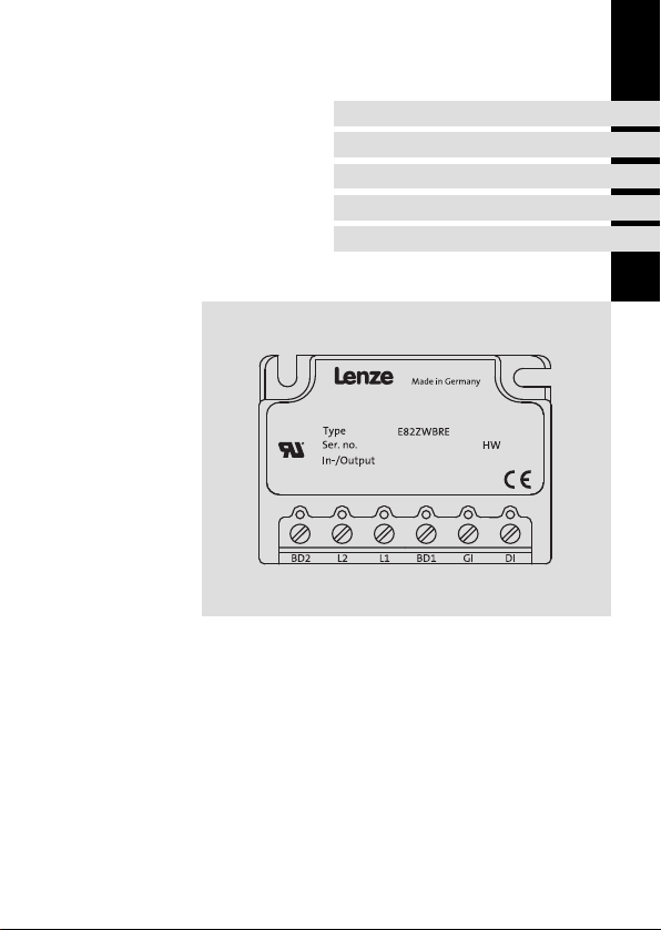
ƒ für Bremsenschalter ab der Typenschildbezeichnung:
E82ZWBRE
Identifikation
82zwbrx_08
E82ZWBRE
Hardwarestand
4
EDK82ZWBRE DE/EN/FR 6.0
Page 5

Über diese Dokumentation
Dokumenthistorie
Dokumenthistorie
Materialnummer Version Beschreibung
.ODn 6.0 05/2014 TD06 UR−Warnings korrigiert,
13233641 5.0 10/2010 TD00 Anforderungen nach UR ergänzt
13201031 4.0 03/2007 TD00 Überarbeitung Kap. "Technische Daten"
13181077 3.0 11/2006 TD00 Überarbeitung Kap. "Technische Daten"
Fehlerkorrekturen
Tipp!
Informationen und Hilfsmittel rund um die Lenze−Produkte finden Sie im
Download−Bereich unter
http://www.Lenze.com
Verwendete Konventionen
Diese Dokumentation verwendet folgende Konventionen zur Unterscheidung verschiedener Arten von Information:
Zahlenschreibweise
Dezimaltrennzeichen
Warnhinweise
UL−Warnhinweise
UR−Warnhinweise
Textauszeichnung
Programmname » « PC−Software
Symbole
Seitenverweis
Punkt Es wird generell der Dezimalpunkt
verwendet.
Zum Beispiel: 1234.56
Werden in englischer und französischer Sprache verwendet.
Zum Beispiel: »Engineer«, »Global
Drive Control« (GDC)
Verweis auf eine andere Seite mit zusätzlichen Informationen
Zum Beispiel: 16 = siehe Seite 16
1
EDK82ZWBRE DE/EN/FR 6.0
5
Page 6

1 Über diese Dokumentation
Verwendete Hinweise
Verwendete Hinweise
Um auf Gefahren und wichtige Informationen hinzuweisen, werden in dieser Dokumentation folgende Piktogramme und Signalwörter verwendet:
Sicherheitshinweise
Aufbau der Sicherheitshinweise:
Gefahr!
(kennzeichnet die Art und die Schwere der Gefahr)
Hinweistext
(beschreibt die Gefahr und gibt Hinweise, wie sie vermieden werden kann)
Piktogramm und Signalwort Bedeutung
Gefahr von Personenschäden durch gefährliche elektrische Spannung
Gefahr!
Gefahr!
Stop!
Hinweis auf eine unmittelbar drohende Gefahr, die den
Tod oder schwere Verletzungen zur Folge haben kann,
wenn nicht die entsprechenden Maßnahmen getroffen
werden.
Gefahr von Personenschäden durch eine allgemeine Gefahrenquelle
Hinweis auf eine unmittelbar drohende Gefahr, die den
Tod oder schwere Verletzungen zur Folge haben kann,
wenn nicht die entsprechenden Maßnahmen getroffen
werden.
Gefahr von Sachschäden
Hinweis auf eine mögliche Gefahr, die Sachschäden zur
Folge haben kann, wenn nicht die entsprechenden Maßnahmen getroffen werden.
6
EDK82ZWBRE DE/EN/FR 6.0
Page 7

Anwendungshinweise
Piktogramm und Signalwort Bedeutung
Über diese Dokumentation
Verwendete Hinweise
1
Hinweis!
Tipp!
Spezielle Sicherheitshinweise und Anwendungshinweise
Piktogramm und Signalwort Bedeutung
Warnings!
Warnings!
Wichtiger Hinweis für die störungsfreie Funktion
Nützlicher Tipp für die einfache Handhabung
Verweis auf andere Dokumentation
Sicherheitshinweis oder Anwendungshinweis für den
Betrieb nach UL− oder CSA−Anforderungen.
Die Maßnahmen sind erforderlich, um die Anforderungen
nach UL oder CSA zu erfüllen.
EDK82ZWBRE DE/EN/FR 6.0
7
Page 8

2 Sicherheitshinweise
Allgemeine Sicherheits− und Anwendungshinweise
2 Sicherheitshinweise
Allgemeine Sicherheits− und Anwendungshinweise
Gefahr!
Wenn Sie die folgenden grundlegenden Sicherheitsmaßnahmen missachten,
kann dies zu schweren Personenschäden und Sachschäden führen:
ƒ Lenze−Antriebs− und Automatisierungskomponenten ...
... ausschließlich bestimmungsgemäß verwenden.
... niemals trotz erkennbarer Schäden in Betrieb nehmen.
... niemals technisch verändern.
... niemals unvollständig montiert in Betrieb nehmen.
... niemals ohne erforderliche Abdeckungen betreiben.
... können während und nach dem Betrieb − ihrer Schutzart entsprechend − spannungsführende, auch bewegliche oder rotierende Teile haben. Oberflächen können heiß sein.
ƒ Alle Vorgaben der beiliegenden und zugehörigen Dokumentation beachten.
Dies ist Voraussetzung für einen sicheren und störungsfreien Betrieb sowie für das Erreichen der angegebenen Produkteigenschaften.
Die in diesem Dokument dargestellten verfahrenstechnischen Hinweise und Schaltungsausschnitte sind Vorschläge, deren Übertragbarkeit auf die jeweilige Anwendung
überprüft werden muss. Für die Eignung der angegebenen Verfahren und Schaltungsvorschläge übernimmt der Hersteller keine Gewähr.
ƒ Alle Arbeiten mit und an Lenze−Antriebs− und Automatisierungskomponenten darf
nur qualifiziertes Fachpersonal ausführen.
Nach IEC 60364 bzw. CENELEC HD 384 sind dies Personen, ...
... die mit Aufstellung, Montage, Inbetriebsetzung und Betrieb des Produkts vertraut
sind.
... die über die entsprechenden Qualifikationen für ihre Tätigkeit verfügen.
... die alle am Einsatzort geltenden Unfallverhütungsvorschriften, Richtlinien und Gesetze kennen und anwenden können.
8
EDK82ZWBRE DE/EN/FR 6.0
Page 9

Allgemeine Sicherheits− und Anwendungshinweise
Gefahr!
Sicherheitshinweise
Gefährliche elektrische Spannung!
An den Anschlüssen des Bremsenschalters können gefährliche elektrische
Spannungen anliegen.
Mögliche Folgen:
ƒ Tod oder schwerste Verletzungen beim Berühren der Anschlussklemmen.
Schutzmaßnahmen:
ƒ Vor allen Arbeiten das Grundgerät und den Bremsenschalter vom Netz
trennen.
ƒ Alle Leistungsklemmen auf Spannungsfreiheit prüfen.
Hinweis!
Um den fehlerfreien Betrieb des Bremsenschalters zu gewährleisten, dürfen
Sie die minimal zulässige Ausschaltdauer nicht unterschreiten. (s. Technische
Daten)
2
EDK82ZWBRE DE/EN/FR 6.0
9
Page 10

2 Sicherheitshinweise
Sicherheitshinweise für die Installation nach UL
Sicherheitshinweise für die Installation nach UL
Warnings!
Conditions of Acceptability:
ƒ These devices should be used within their marked Recognized ratings.
ƒ These devices should be mounted within a suitable ultimate enclosure
with proper spacings being maintained.
ƒ Maximum surrounding air temperature 60 °C.
ƒ Use 75°C copper wires only, min. wire size 20 AWG.
ƒ These devices are intended for use with Power Conversion Equipment (e.g
for use with of Lenze Drives as registered in File E132659 Vol.11, Sec. 1
(series E82MV)).
10
EDK82ZWBRE DE/EN/FR 6.0
Page 11

Allgemeine Daten und Einsatzbedingungen
Technische Daten
3 Technische Daten
Allgemeine Daten und Einsatzbedingungen
Funktion
Der elektronische Bremsenschalter ermöglicht die Ansteuerung der elektromagnetischen
Haltebremse in einem Bremsmotor.
Einsetzbarkeit
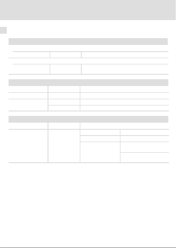
Der elektronische Bremsenschalter ist einsetzbar mit den Grundgeräten:
Grundgerät Einbauort
Frequenzumrichter 8200 motec E82MVxxx_4B
mit Funktionsmodul Standard-I/O oder Application-I/O
Frequenzumrichter 8200 motec E82MVxxx_4B
Varianten V152, V153
Frequenzumrichter 8200 vector E82xVxxxKxC
mit Funktionsmodul Standard-I/O oder Application-I/O
Andere Lenze−Antriebsregler
mit Digitalausgang +15 ... +30 V, 5 ... 10 mA
Im motec
Ansteuerung über den Digitalausgang des
Funktionsmoduls
Im motec
Ansteuerung über den integrierten Digitalausgang des motec
Im Schaltschrank
Ansteuerung über den Digitalausgang des
Funktionsmoduls
Im Schaltschrank
3
EDK82ZWBRE DE/EN/FR 6.0
11
Page 12
3 Technische Daten
Allgemeine Daten und Einsatzbedingungen
Allgemeine Daten
Konformität und Approbation
Konformität
CE
Approbation
UR UL 508C Power Conversion Equipment − Component
Personenschutz und Geräteschutz
Schutzart EN 60529
Schutzmaßnahmen Gegen Kurzschluss
Leitungsschutz
EMV
Störaussendung EN 61800−3
Störfestigkeit EN 61800−3
2006/95/EG Niederspannungsrichtlinie
(File No. E132659) für USA
IP00
EN 60204−1 6 A, Auslösecharakteristik "B" oder "C"
UL 248 5 A
Leitungsgeführt, Kategorie C2.
Burst auf Netzleitung: 2 kV/5 kHz
Burst auf Steuerleitung: 2 kV/5 kHz
Surge auf Netzleitung:
1 kV (1.2 ms/50 ms;
Phase − Phase)
2 kV (1.2 ms/50 ms;
Phase − PE)
12
EDK82ZWBRE DE/EN/FR 6.0
Page 13

Allgemeine Daten und Einsatzbedingungen
Einsatzbedingungen
Umgebungsbedingungen
Klimatisch
Lagerung
Transport IEC/EN 60721−3−2 2K3 (−25 ... +70 °C)
Betrieb IEC/EN 60721−3−3 3K3 (−10 ... +55 °C)
Verschmutzung EN 61800−5−1 Verschmutzungsgrad 2
Aufstellhöhe < 4000 m üNN
Mechanisch
Rüttelfestigkeit Germanischer
IEC/EN 60721−3−1 1K3 (−25 ... +60 °C)
Lloyd
Allgemeine Bedingungen
Beschleunigungsfest bis 2 g
Technische Daten
3
EDK82ZWBRE DE/EN/FR 6.0
13
Page 14
3 Technische Daten
Bemessungsdaten
Bemessungsdaten
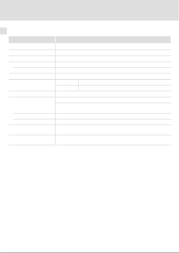
Bereich Werte
Eingangsspannung 3/PE AC 400 V (AC 320 ... 550 V), 45 ... 65 Hz
Eingangsstrom AC 0.1 ... 0.61 A
Ausgangsspannung
DC 180 V bei Netzspannung AC 400 V
Maximaler Bremsenstrom
(pilot duty)
Steuereingang
Steuerspannung
Steuerstrom 5 ... 10 mA
Schutzfunktion Verpolungssicher bis DC 60 V
Min. zulässige Aus-
schaltdauer
Maximal anschließbarer
Leitungsquerschnitt
DC 225 V bei Netzspannung AC 500 V
DC 0.47 A Einbau in 8200 motec
DC 0.61 A Einbau im Schaltschrank
DC 24 V, SPS−Pegel
HIGH
LOW
t
off
1.5 mm
AWG 16
>20 ms
2
DC +15 ... 30 V
DC 0 ... +3 V
14
EDK82ZWBRE DE/EN/FR 6.0
Page 15

Technische Daten
Bemessungsdaten
Zulässige Schalthäufigkeiten
Empfohlene Bremse Leistung Spule: Spannung DC 180 V Zulässige Schalthäufigkeit
Typ P [W] L [H] I [A] (20 °C) [1/min]
BFK457−06E
BFK458−06E
BFK457−08E
BFK458−08E
BFK457−10E
BFK458−10E
BFK457−12E
BFK458−12E
BFK457−14E
BFK458−14E
BFK457−16E
BFK458−16E
BFK457−18E
BFK458−18E
BFK457−20E
BFK458−20E
BFK457−25E
BFK458−25E
1)
1)
1)
1)
1)
Betrieb nur erlaubt, wenn der Bremsenschalter im Schaltschrank montiert ist
20
25 50 0.14 60
30 69 0.17 60
40 81 0.22 40
50 78 0.28 30
55 102 0.31 20
85 77 0.47 10
100 92 0.56 8
110 102 0.61 6
60 0.11 60
3
EDK82ZWBRE DE/EN/FR 6.0
15
Page 16
4 Mechanische Installation
Einbau im Schaltschrank
4 Mechanische Installation
Einbau im Schaltschrank
Montageort
Bedingungen
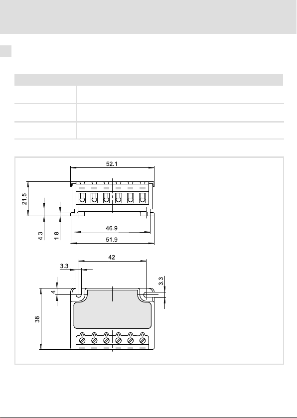
Einbaufreiräume Für gute Belüftung sorgen. Die vom Bremsenschalter erzeugte Wärme muss
Befestigung Mit 2 Schrauben M3
Gewicht 0.1 kg
Abmessungen
ungehindert abgeführt werden.
Anzugsmoment: 0.7 Nm (6 lb−in)
Abb. 1 Abmessungen
Alle Maße in Millimeter.
16
82zwbrx_02
EDK82ZWBRE DE/EN/FR 6.0
Page 17
Einbau in 8200 motec, Typ E82MV551_4B ... E82MV222_4B
Mechanische Installation
Einbau in 8200 motec, Typ E82MV551_4B ... E82MV222_4B
0.7 Nm
6 lbin
M3 10×
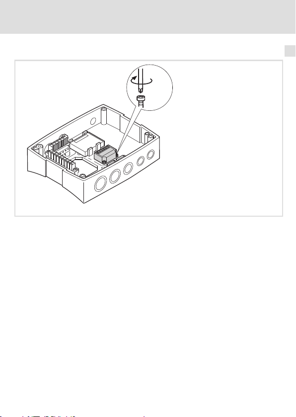
Abb. 2 Bremsenschalter in 8200 motec einbauen
4
82zwbrx_04
EDK82ZWBRE DE/EN/FR 6.0
17
Page 18
4 Mechanische Installation
Einbau in 8200 motec, Typ E82MV302_4B ... E82MV752_4B
Einbau in 8200 motec, Typ E82MV302_4B ... E82MV752_4B
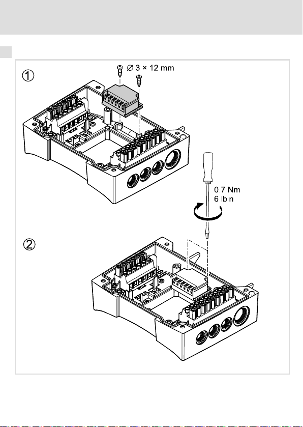
Abb. 3 Bremsenschalter in 8200 motec einbauen
18
82zwbrx_09
EDK82ZWBRE DE/EN/FR 6.0
Page 19

Elektrische Installation
Verdrahtung im Schaltschrank
5 Elektrische Installation
Verdrahtung im Schaltschrank
Hinweis!
Wird der Bremsenschalter im Schaltschrank eingesetzt, ist ein separater
Leitungsschutz in der Zuleitung zum Bremsenschalter erforderlich.
5
EDK82ZWBRE DE/EN/FR 6.0
19
Page 20
5 Elektrische Installation
Verdrahtung im Schaltschrank
3/PE AC 400 V … 500 V
L1
L2
L3
PE
B6 A/C6A (EN 60204-1)
E82ZWBRE
GI DIL2 L1
BD1BD2
BD1=+
+-
}
BD2=-
M
3~
DC 180 V (AC 400 V)
DC 225 V (AC 500 V)
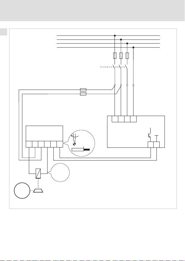
Abb. 4 Bremsenschalter verdrahten
F10
5A (UL 248)
0.5 … 0.6 Nm
4.4 … 5.3 lb-in
6mm
0.24 in
F1...F3
K10
L3
L2
L1 PE
A1
DIGOUT
+15 … +30 V,
5 … 10 mA
GND
82zwbrx_10
A1 Lenze−Antriebsregler mit Digitalausgang
F10 Zusätzlicher Leitungsschutz
20
EDK82ZWBRE DE/EN/FR 6.0
Page 21

Verdrahtung im 8200 motec
3/PEAC400V…500V
L1
L2
L3
N
PE
F1...F3
K10
Elektrische Installation
Verdrahtung im 8200 motec
5
8200 motec
X1.1
E82ZWBRE
M
3~
DC 180 V (AC 400 V)
DC 225 V (AC 500 V)
Abb. 5 Bremsenschalter verdrahten
Legende siehe nächste Seite
EDK82ZWBRE DE/EN/FR 6.0
L3
L1 PE
L2
BD1BD2
GI DIL2 L1
+-
}
BD1=+
BD2=-
0.5 … 0.6 Nm
4.4 … 5.3 lb-in
6mm
0.24 in
Z1
Z1
GI DI
GI DI
A1
K12
GND1GND1
7720
GND
7
K14K11
+20 V
GND2
………
0
5939
A1
+20 V
1
2
……
82zwbrx_11
21
+20 V
……
20
59
Z1
GND1
720
Page 22

5 Elektrische Installation
Verdrahtung im 8200 motec
Anschlussvariante 1:
Z1 Funktionsmodul Standard−I/O
Die interne Spannungsquelle des Funktionsmoduls versorgt den Digitalausgang.
Ansteuerung des Bremsenschalters über den Digitalausgang des Funktionsmoduls.
Anschlussvariante 2:
Z1 Funktionsmodul Application−I/O
Die interne Spannungsquelle des Funktionsmoduls versorgt den Digitalausgang.
Ansteuerung des Bremsenschalters über den Digitalausgang des Funktionsmoduls.
Anschlussvariante 3 (nur mit 8200 motec, Variante V152 oder V153):
Z1 Funktionsmodul
Die interne Spannungsquelle des Funktionsmoduls versorgt den Digitalausgang des
motec.
Ansteuerung des Bremsenschalters über den Digitalausgang des motec.
Hinweis:
Statt über die interne Spannungsquelle des Funktionsmoduls können Sie den
Digitalausgang des motec auch über eine externe Spannungsquelle DC 24 V versorgen.
Klemmendaten
Leiterquerschnitt Anzugsmoment
[mm2] [AWG] [Nm] [lb−in]
flexibel
mit Aderendhülse
0.5 ... 1.5
20 ... 16 0.5 ... 0.6 4.5 ... 6.2
22
EDK82ZWBRE DE/EN/FR 6.0
Page 23

Contents i
1 About this documentation 24. . . . . . . . . . . . . . . . . . . . . . . . . . . . . . . . . . . . . . . . . . .
Target group 24. . . . . . . . . . . . . . . . . . . . . . . . . . . . . . . . . . . . . . . . . . . . . . . . . . . . . .
Validity information 24. . . . . . . . . . . . . . . . . . . . . . . . . . . . . . . . . . . . . . . . . . . . . . . .
Document history 25. . . . . . . . . . . . . . . . . . . . . . . . . . . . . . . . . . . . . . . . . . . . . . . . . .
Conventions used 25. . . . . . . . . . . . . . . . . . . . . . . . . . . . . . . . . . . . . . . . . . . . . . . . . .
Notes used 26. . . . . . . . . . . . . . . . . . . . . . . . . . . . . . . . . . . . . . . . . . . . . . . . . . . . . . . .
2 Safety instructions 28. . . . . . . . . . . . . . . . . . . . . . . . . . . . . . . . . . . . . . . . . . . . . . . . .
General safety and application notes 28. . . . . . . . . . . . . . . . . . . . . . . . . . . . . . . . . .
Safety instructions for the installation according to UL 30. . . . . . . . . . . . . . . . . . . .
3 Technical data 31. . . . . . . . . . . . . . . . . . . . . . . . . . . . . . . . . . . . . . . . . . . . . . . . . . . . .
General data and operating conditions 31. . . . . . . . . . . . . . . . . . . . . . . . . . . . . . .
Rated data 34. . . . . . . . . . . . . . . . . . . . . . . . . . . . . . . . . . . . . . . . . . . . . . . . . . . . . . . .
4 Mechanical installation 36. . . . . . . . . . . . . . . . . . . . . . . . . . . . . . . . . . . . . . . . . . . . .
Installation in the control cabinet 36. . . . . . . . . . . . . . . . . . . . . . . . . . . . . . . . . . . . .
Installation in 8200 motec, type E82MV551_4B ... E82MV222_4B 37. . . . . . . . . . .
Installation in 8200 motec, type E82MV302_4B ... E82MV752_4B 38. . . . . . . . . . .
5 Electrical installation 39. . . . . . . . . . . . . . . . . . . . . . . . . . . . . . . . . . . . . . . . . . . . . . .
Wiring in the control cabinet 39. . . . . . . . . . . . . . . . . . . . . . . . . . . . . . . . . . . . . . . .
Wiring in the 8200 motec 41. . . . . . . . . . . . . . . . . . . . . . . . . . . . . . . . . . . . . . . . . .
EDK82ZWBRE DE/EN/FR 6.0
23
Page 24

1 About this documentation
Target group
0Fig. 0Tab. 0
1 About this documentation
Target group
This documentation is directed at qualified skilled personnel according to IEC 60364.
Qualified skilled personnel are persons who have the required qualifications to carry out all
activities involved in installing, mounting, commissioning, and operating the product.
Validity information
This documentation is only valid:
ƒ together with the corresponding documentation for the standard devices permitted
for the application.
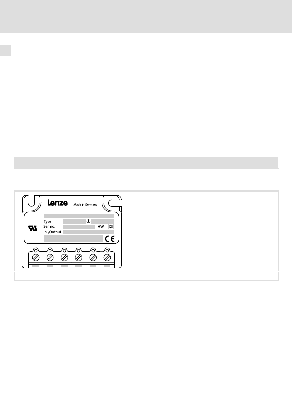
ƒ for brake switches with the below nameplate data or higher
E82ZWBRE
Identification
82zwbrx_08
E82ZWBRE
Hardware version
24
EDK82ZWBRE DE/EN/FR 6.0
Page 25

About this documentation
Document history
Document history
Material number Version Description
.ODn 6.0 05/2014 TD06 Correction of UR warnings,
13233641 5.0 10/2010 TD00 UR requirements added
13201031 4.0 03/2007 TD00 Review of chapter "Technical Data"
13181077 3.0 11/2006 TD00 Review of chapter "Technical Data"
Error corrections
Tip!
Information and auxiliary devices related to the Lenze products can be found
in the download area at
http://www.Lenze.com
Conventions used
This documentation uses the following conventions to distinguish between different types
of information:
Spelling of numbers
Decimal separator
Warnings
UL warnings
UR warnings
Text
Program name » « PC software
Icons
Page reference
Point In general, the decimal point is used.
For instance: 1234.56
Given in English and French
For example: »Engineer«, »Global
Drive Control« (GDC)
Reference to another page with
additional information
For instance: 16 = see page 16
1
EDK82ZWBRE DE/EN/FR 6.0
25
Page 26

1 About this documentation
Notes used
Notes used
The following pictographs and signal words are used in this documentation to indicate
dangers and important information:
Safety instructions
Structure of safety instructions:
Danger!
(characterises the type and severity of danger)
Note
(describes the danger and gives information about how to prevent dangerous
situations)
Pictograph and signal word Meaning
Danger of personal injury through dangerous electrical
Danger!
Danger!
Stop!
voltage.
Reference to an imminent danger that may result in
death or serious personal injury if the corresponding
measures are not taken.
Danger of personal injury through a general source of
danger.
Reference to an imminent danger that may result in
death or serious personal injury if the corresponding
measures are not taken.
Danger of property damage.
Reference to a possible danger that may result in
property damage if the corresponding measures are not
taken.
26
EDK82ZWBRE DE/EN/FR 6.0
Page 27

Application notes
Pictograph and signal word Meaning
About this documentation
Notes used
1
Note!
Tip!
Special safety instructions and application notes
Pictograph and signal word Meaning
Warnings!
Warnings!
Important note to ensure troublefree operation
Useful tip for simple handling
Reference to another documentation
Safety note or application note for the operation
according to UL or CSA requirements.
The measures are required to meet the requirements
according to UL or CSA.
EDK82ZWBRE DE/EN/FR 6.0
27
Page 28

2 Safety instructions
General safety and application notes
2 Safety instructions
General safety and application notes
Danger!
Disregarding the following basic safety measures may lead to severe personal
injury and damage to material assets!
ƒ Lenze drive and automation components ...
... must only be used for the intended purpose.
... must never be operated if damaged.
... must never be subjected to technical modifications.
... must never be operated unless completely assembled.
... must never be operated without the covers/guards.
... can − depending on their degree of protection − have live, movable or rotating parts
during or after operation. Surfaces can be hot.
ƒ All specifications of the corresponding enclosed documentation must be observed.
This is vital for a safe and trouble−free operation and for achieving the specified product
features.
The procedural notes and circuit details provided in this document are proposals which
the user must check for suitability for his application. The manufacturer does not accept
any liability for the suitability of the specified procedures and circuit proposals.
ƒ Only qualified skilled personnel are permitted to work with or on Lenze drive and
automation components.
According to IEC 60364 or CENELEC HD 384, these are persons ...
... who are familiar with the installation, assembly, commissioning and operation of the
product,
... possess the appropriate qualifications for their work,
... and are acquainted with and can apply all the accident prevent regulations, directives
and laws applicable at the place of use.
28
EDK82ZWBRE DE/EN/FR 6.0
Page 29

General safety and application notes
Danger!
Safety instructions
Dangerous electrical voltage!
Dangerous electrical voltages may be applied to the connections of the brake
switch.
Possible consequences:
ƒ Death or severe injuries when touching the terminals.
Protective measures:
ƒ Disconnect the standard device and the brake switch from the mains
before carrying out any operations.
ƒ Check that all power terminals are deenergised.
Note!
In order to guarantee an error−free operation of the brake switch, observe the
minimally required disconnection time (see technical data)
2
EDK82ZWBRE DE/EN/FR 6.0
29
Page 30

2 Safety instructions
Safety instructions for the installation according to UL
Safety instructions for the installation according to UL
Warnings!
Conditions of Acceptability:
ƒ These devices should be used within their marked Recognized ratings.
ƒ These devices should be mounted within a suitable ultimate enclosure
with proper spacings being maintained.
ƒ Maximum surrounding air temperature 60 °C.
ƒ Use 75°C copper wires only, min. wire size 20 AWG.
ƒ These devices are intended for use with Power Conversion Equipment (e.g
for use with of Lenze Drives as registered in File E132659 Vol.11, Sec. 1
(series E82MV)).
30
EDK82ZWBRE DE/EN/FR 6.0
Page 31

General data and operating conditions
Technical data
3 Technical data
General data and operating conditions
Function
The electronic brake switch enables the control of the electromechanical holding brake in
a brake motor.
Application range
The electronic brake switch can be used with the following standard devices:
Standard device Mounting place
8200 motec frequency inverter E82MVxxx_4B
with standard I/O or application I/O function module
8200 motec frequency inverter E82MVxxx_4B
Variants V152, V153
8200 vector frequency inverter E82xVxxxKxC
with standard I/O or application I/O function module
Other Lenze controllers
with digital output +15 ... +30 V, 5 ... 10 mA
In the motec
Activation via the digital output of the
function module
In the motec
Activation via the integrated digital
output of the motec
In the control cabinet
Activation via the digital output of the
function module
In the control cabinet
3
EDK82ZWBRE DE/EN/FR 6.0
31
Page 32

3 Technical data
General data and operating conditions
General data
Conformity and approval
Conformity
CE
Approval
UR UL 508C Power Conversion Equipment − Component
Protection of persons and equipment
Enclosure EN 60529
Protective measures Against short circuit
Cable protection
EMC
Noise emission EN 61800−3
Noise immunity EN 61800−3
2006/95/EC Low−Voltage Directive
(file no. E132659) for USA
IP00
EN 60204−1 6 A, tripping characteristic "B" or "C"
UL 248 5 A
Conducted, category C2.
Burst on mains cable: 2 kV/5 kHz
Burst on control cable: 2 kV/5 kHz
Surge on mains cable:
1 kV (1.2 ms/50 ms;
phase − phase)
2 kV (1.2 ms/50 ms;
phase − PE)
32
EDK82ZWBRE DE/EN/FR 6.0
Page 33

General data and operating conditions
Operating conditions
Ambient conditions
Climatic
Storage
Transport IEC/EN 60721−3−2 2K3 (−25 ... +70 °C)
Operation IEC/EN 60721−3−3 3K3 (−10 ... +55 °C)
Pollution EN 61800−5−1 Degree of pollution 2
Site altitude < 4000 m amsl
Mechanical
Vibration resistance Germanischer
IEC/EN 60721−3−1 1K3 (−25 ... +60 °C)
Lloyd
General conditions
Acceleration−resistant up to 2 g
Technical data
3
EDK82ZWBRE DE/EN/FR 6.0
33
Page 34

3 Technical data
Rated data
Rated data
Range Values
Input voltage 3/PE AC 400 V (AC 320 ... 550 V), 45 ... 65 Hz
Input current AC 0.1 ... 0.61A
Output voltage
DC 180 V at AC 400 V mains voltage
Maximum brake current
(pilot duty)
Control input
Control voltage
Control current 5 ... 10 mA
Protective function Protected against polarity reversal until DC 60 V
Min. permissible
switch−off time
Maximally connectable
cable cross−section
DC 225 V at AC 500 V mains voltage
DC 0.47 A Installation in 8200 motec
DC 0.61 A Installation in control cabinet
DC 24 V, PLC−level
HIGH
LOW
t
off
1.5 mm
AWG 16
>20ms
2
DC +15 ... 30V
DC 0 ... +3 V
34
EDK82ZWBRE DE/EN/FR 6.0
Page 35

Technical data
Rated data
Permissible switching rates
Recommended brake Power Coil: voltage DC 180 V Permissible switching rate
Type P [W] L [H] I [A] (20 °C) [1/min]
BFK457−06E
BFK458−06E
BFK457−08E
BFK458−08E
BFK457−10E
BFK458−10E
BFK457−12E
BFK458−12E
BFK457−14E
BFK458−14E
BFK457−16E
BFK458−16E
BFK457−18E
BFK458−18E
BFK457−20E
BFK458−20E
BFK457−25E
BFK458−25E
1)
1)
1)
1)
1)
Operation only permitted if the brake switch is mounted in the control cabinet
20
25 50 0.14 60
30 69 0.17 60
40 81 0.22 40
50 78 0.28 30
55 102 0.31 20
85 77 0.47 10
100 92 0.56 8
110 102 0.61 6
60 0.11 60
3
EDK82ZWBRE DE/EN/FR 6.0
35
Page 36

4 Mechanical installation
Installation in the control cabinet
4 Mechanical installation
Installation in the control cabinet
Mounting location
Conditions
Free spaces Ensure good ventilation. The heat generated by the brake switch must be
Fastening Using two M3 screws
Weight 0.1 kg
Dimensions
dissipated freely.
Starting torque: 0.7 Nm (6 lb−in)
Fig. 1 Dimensions
All dimensions in millimetres.
36
82zwbrx_02
EDK82ZWBRE DE/EN/FR 6.0
Page 37

Installation in 8200 motec, type E82MV551_4B ... E82MV222_4B
Mechanical installation
Installation in 8200 motec, type E82MV551_4B ... E82MV222_4B
0.7 Nm
6 lbin
M3 10×
Fig. 2 Brake switch installation in 8200 motec
4
82zwbrx_04
EDK82ZWBRE DE/EN/FR 6.0
37
Page 38

4 Mechanical installation
Installation in 8200 motec, type E82MV302_4B ... E82MV752_4B
Installation in 8200 motec, type E82MV302_4B ... E82MV752_4B
Fig. 3 Brake switch installation in 8200 motec
38
82zwbrx_09
EDK82ZWBRE DE/EN/FR 6.0
Page 39

Electrical installation
Wiring in the control cabinet
5 Electrical installation
Wiring in the control cabinet
Note!
If the brake switch is used in the control cabinet, a separate cable protection is
required in the supply cable of the brake switch.
5
EDK82ZWBRE DE/EN/FR 6.0
39
Page 40

5 Electrical installation
Wiring in the control cabinet
3/PE AC 400 V … 500 V
L1
L2
L3
PE
B6 A/C6A (EN 60204-1)
E82ZWBRE
GI DIL2 L1
BD1BD2
BD1=+
+-
}
BD2=-
M
3~
DC 180 V (AC 400 V)
DC 225 V (AC 500 V)
Fig. 4 Wiring of brake switch
F10
5A (UL 248)
0.5 … 0.6 Nm
4.4 … 5.3 lb-in
6mm
0.24 in
F1...F3
K10
L3
L2
L1 PE
A1
DIGOUT
+15 … +30 V,
5 … 10 mA
GND
82zwbrx_10
A1 Lenze controller with digital output
F10 Additional cable protection
40
EDK82ZWBRE DE/EN/FR 6.0
Page 41

Wiring in the 8200 motec
3/PEAC400V…500V
L1
L2
L3
N
PE
F1...F3
K10
Electrical installation
Wiring in the 8200 motec
5
8200 motec
X1.1
L3
L1 PE
L2
E82ZWBRE
BD1BD2
GI DIL2 L1
BD1=+
+-
}
BD2=-
M
3~
DC 180 V (AC 400 V)
DC 225 V (AC 500 V)
Fig. 5 Wiring of brake switch
For legend see next page
EDK82ZWBRE DE/EN/FR 6.0
0.5 … 0.6 Nm
4.4 … 5.3 lb-in
6mm
0.24 in
Z1
Z1
GI DI
GI DI
A1
K12
GND1GND1
7720
GND
7
K14K11
+20 V
GND2
………
0
5939
A1
+20 V
1
2
……
82zwbrx_11
41
+20 V
……
20
59
Z1
GND1
720
Page 42

5 Electrical installation
Wiring in the 8200 motec
Connection variant 1:
Z1 Standard I/O function module
The internal voltage source of the function module supplies the digital output.
Control of the brake switch via the digital output of the function module.
Connection variant 2:
Z1 Application I/O function module
The internal voltage source of the function module supplies the digital output.
Control of the brake switch via the digital output of the function module.
Connection variant 3 (only with 8200 motec, variant V152 or V153):
Z1 Function module
The internal voltage source of the function module supplies the digital output of the
motec.
Control of the brake switch via the digital output of the motec.
Note:
Instead of using the internal voltage source of the function module, you can also supply
the digital output of the motec via an external 24 V DC voltage source.
Terminal data
Conductor cross−section Tightening torque
[mm2] [AWG] [Nm] [lb−in]
Flexible
With wire end
ferrule
0.5 ... 1.5
20 ... 16 0.5 ... 0.6 4.5 ... 6.2
42
EDK82ZWBRE DE/EN/FR 6.0
Page 43

Sommaire i
1 Présentation du document 44. . . . . . . . . . . . . . . . . . . . . . . . . . . . . . . . . . . . . . . . . . .
Public visé 44. . . . . . . . . . . . . . . . . . . . . . . . . . . . . . . . . . . . . . . . . . . . . . . . . . . . . . . .
Validité 44. . . . . . . . . . . . . . . . . . . . . . . . . . . . . . . . . . . . . . . . . . . . . . . . . . . . . . . . . . .
Historique du document 45. . . . . . . . . . . . . . . . . . . . . . . . . . . . . . . . . . . . . . . . . . . . .
Conventions utilisées 45. . . . . . . . . . . . . . . . . . . . . . . . . . . . . . . . . . . . . . . . . . . . . . .
Consignes utilisées 46. . . . . . . . . . . . . . . . . . . . . . . . . . . . . . . . . . . . . . . . . . . . . . . . .
2 Consignes de sécurité 48. . . . . . . . . . . . . . . . . . . . . . . . . . . . . . . . . . . . . . . . . . . . . . .
Instructions générales de sécurité et d’utilisation 48. . . . . . . . . . . . . . . . . . . . . . . .
Consignes de sécurité pour l’installation selon UL 50. . . . . . . . . . . . . . . . . . . . . . . .
3 Spécifications techniques 51. . . . . . . . . . . . . . . . . . . . . . . . . . . . . . . . . . . . . . . . . . .
Caractéristiques générales et conditions d’utilisation 51. . . . . . . . . . . . . . . . . . . .
Caractéristiques assignées 54. . . . . . . . . . . . . . . . . . . . . . . . . . . . . . . . . . . . . . . . . . .
4 Installation mécanique 56. . . . . . . . . . . . . . . . . . . . . . . . . . . . . . . . . . . . . . . . . . . . . .
Montage sur panneau en armoire électrique 56. . . . . . . . . . . . . . . . . . . . . . . . . . . .
Intégration dans le 8200 motec, type E82MV551_4B ... E82MV222_4B 57. . . . . . .
Intégration dans le 8200 motec, type E82MV302_4B ... E82MV752_4B 58. . . . . . .
5 Installation électrique 59. . . . . . . . . . . . . . . . . . . . . . . . . . . . . . . . . . . . . . . . . . . . . . .
Câblage dans l’armoire électrique 59. . . . . . . . . . . . . . . . . . . . . . . . . . . . . . . . . . . .
Câblage dans le 8200 motec 61. . . . . . . . . . . . . . . . . . . . . . . . . . . . . . . . . . . . . . . .
EDK82ZWBRE DE/EN/FR 6.0
43
Page 44

1 Présentation du document
Public visé
0Fig. 0Tab. 0
1 Présentation du document
Public visé
Cette documentation s’adresse à un personnel qualifié et habilité conformément à la
norme CEI 60364.
On entend par "personnel qualifié et habilité" des personnes compétentes en matière
d’installation, de montage, de mise en service et de fonctionnement du produit et
possédant les qualifications correspondant à leurs activités.
Validité
Ce document est uniquement valable :
ƒ avec la documentation relative aux appareils de base compatibles,
ƒ pour les contacteurs de frein à partir de la version suivante (voir plaque
signalétique) :
E82ZWBRE
Identification
82zwbrx_08
E82ZWBRE
Version matérielle
44
EDK82ZWBRE DE/EN/FR 6.0
Page 45

Présentation du document
Historique du document
Historique du document
Numéro de matériel Version Description
.ODn 6.0 05/2014 TD06 Révision des UR−Warnings,
13233641 5.0 10/2010 TD00 Chapitre complété : exigences selon UR
13201031 4.0 03/2007 TD00 Chapitre revu : "Spécifications techniques"
13181077 3.0 11/2006 TD00 Chapitre revu : "Spécifications techniques"
Correction d’erreurs
Conseil !
Toutes les informations relatives aux produits Lenze peuvent être téléchargées
sur notre site à l’adresse suivante :
http://www.Lenze.com
Conventions utilisées
Pour distinguer les différents types d’information, cette documentation utilise les
conventions suivantes :
Représentation des chiffres
Séparateur décimal
Consignes préventives
Consignes préventives UL
Consignes préventives UR
Mise en évidence de textes spéciaux
Nom de programme » « Logiciel pour PC
Pictogrammes
Renvoi à la page
Point Le point décimal est généralement
utilisé.
Exemple : 1234.56
En anglais et en français
Exemple : »Engineer«, »Global Drive
Control« (GDC)
Renvoi à une autre page contenant
des informations complémentaires
Exemple : 16 = voir page 16
1
EDK82ZWBRE DE/EN/FR 6.0
45
Page 46

1 Présentation du document
Consignes utilisées
Consignes utilisées
Pour indiquer des risques et des informations importantes, la présente documentation
utilise les mots et pictogrammes suivants :
Consignes de sécurité
Présentation des consignes de sécurité
Danger !
(Le pictogramme indique le type de risque.)
Explication
(L’explication décrit le risque et les moyens de l’éviter.)
Pictogramme et mot associé Explication
Situation dangereuse pour les personnes en raison d’une
tension électrique élevée
Danger !
Danger !
Stop !
Indication d’un danger imminent qui peut avoir pour
conséquences des blessures mortelles ou très graves en
cas de non−respect des consignes de sécurité
correspondantes
Situation dangereuse pour les personnes en raison d’un
danger d’ordre général
Indication d’un danger imminent qui peut avoir pour
conséquences des blessures mortelles ou très graves en
cas de non−respect des consignes de sécurité
correspondantes
Risques de dégâts matériels
Indication d’un risque potentiel qui peut avoir pour
conséquences des dégâts matériels en cas de non−respect
des consignes de sécurité correspondantes
46
EDK82ZWBRE DE/EN/FR 6.0
Page 47

Consignes d’utilisation
Pictogramme et mot associé Explication
Présentation du document
Consignes utilisées
1
Remarque
importante !
Conseil !
Consignes de sécurité et d’utilisation spéciales
Pictogramme et mot associé Description
Avertissements !
Avertissements !
Remarque importante pour assurer un fonctionnement
correct
Conseil utile pour faciliter la mise en uvre
Renvoi à une autre documentation
Consigne de sécurité ou d’utilisation pour le
fonctionnement selon les normes UL ou CSA.
Les mesures sont requises pour répondre aux exigences
des normes UL ou CSA.
EDK82ZWBRE DE/EN/FR 6.0
47
Page 48

2 Consignes de sécurité
Instructions générales de sécurité et d’utilisation
2 Consignes de sécurité
Instructions générales de sécurité et d’utilisation
Danger !
Le non−respect des consignes fondamentales de sécurité suivantes peut
entraîner des blessures et des dommages matériels graves.
ƒ Les composants d’entraînement et d’automatisation Lenze ...
... doivent exclusivement être utilisés conformément à leur fonction.
... ne doivent jamais être mis en service si des dommages sont décelés.
... ne doivent jamais être modifiés d’un point de vue technique.
... ne doivent jamais être mis en service s’ils ne sont pas montés intégralement.
... ne doivent jamais être mis en service sans le capot obligatoire.
... peuvent − selon l’indice de protection − contenir des pièces sous tension, en
mouvement ou en rotation. Les surfaces peuvent être brûlantes.
ƒ Respecter les consignes et les indications contenues dans la documentation
concernée.
Il s’agit de la condition préalable pour garantir un fonctionnement sûr et fiable et pour
obtenir les caractéristiques du produit indiquées.
Les procédures à suivre et les plans de raccordement fournis constituent des
recommandations dont l’adéquation avec l’application concernée doit être vérifiée.
Lenze n’assumera aucune responsabilité pour les dommages liés à un problème
d’adéquation des procédures et plans de raccordements indiqués.
ƒ Les travaux réalisés avec et au niveau des composants d’entraînement et
d’automatisation Lenze ne doivent être exécutés que par un personnel qualifié et
habilité.
Selon les normes CEI 60364 ou CENELEC HD 384, ces personnes doivent ...
... connaître parfaitement l’installation, le montage, la mise en service et le
fonctionnement du produit.
... posséder les qualifications appropriées pour l’exercice de leur activité.
... connaître toutes les prescriptions pour la prévention d’accidents, directives et lois
applicables sur le lieu d’utilisation et être en mesure de les appliquer.
48
EDK82ZWBRE DE/EN/FR 6.0
Page 49

Instructions générales de sécurité et d’utilisation
Danger !
Consignes de sécurité
Tension électrique dangereuse !
Des tensions électriques dangereuses peuvent circuler dans les raccordements
du contacteur de frein.
Risques encourus :
ƒ Mort ou blessures très graves en cas de contact accidentel avec les bornes
de raccordement.
Mesures de protection :
ƒ Couper l’appareil de base et le contacteur de frein du réseau avant tous
travaux.
ƒ S’assurer que toutes les bornes de puissance sont hors tension.
Remarque importante !
Pour assurer un fonctionnement correct du contacteur de frein, il faut
impérativement respecter la durée de mise hors tension minimale requise (voir
Specifications techniques).
2
EDK82ZWBRE DE/EN/FR 6.0
49
Page 50

2 Consignes de sécurité
Consignes de sécurité pour l’installation selon UL
Consignes de sécurité pour l’installation selon U
L
Avertissements !
Conditions d’acceptabilité :
ƒ Ces équipements doivent être utilisés conformément aux caractéristiques
assignées de référence reconnues.
ƒ Les équipements doivent être montés dans un coffret adapté en respectant
les espaces minimums prescrits.
ƒ Température ambiante maximale : 60 °C.
ƒ Utiliser exclusivement des conducteurs en cuivre 75°C de 20 AWG
minimum.
ƒ Ces équipements sont destinés à être utilisés avec des convertisseurs de
puissance (systèmes d’entraînement Lenze référencés dans le dossier
E132659, vol.11, sec. 1 [série E82MV]).
50
EDK82ZWBRE DE/EN/FR 6.0
Page 51

Caractéristiques générales et conditions d’utilisation
Spécifications techniques
3 Spécifications techniques
Caractéristiques générales et conditions d’utilisation
Fonction
Le contacteur de frein électronique permet de piloter le frein de parking électromagnétique
intégré dans un moteur−frein.
Utilisation
Le contacteur de frein électronique est compatible avec les appareils de base suivants :
Appareil de base Emplacement de montage
Convertisseur de fréquence 8200 motec E82MVxxx_4B
avec module de fonction ES standard ou E/S application
Convertisseur de fréquence 8200 motec E82MVxxx_4B
Variante V152, V153
Convertisseur de fréquence 8200 vector E82xVxxxKxC
avec module de fonction ES standard ou E/S application
Autres variateurs de vitesse Lenze
avec sortie numérique +15 ... +30 V, 5 ... 10 mA
Dans le motec
Pilotage via sortie numérique du module
de fonction
Dans le motec
Pilotage via sortie numérique intégrée du
motec
En armoire électrique
Pilotage via sortie numérique du module
de fonction
En armoire électrique
3
EDK82ZWBRE DE/EN/FR 6.0
51
Page 52

3 Spécifications techniques
Caractéristiques générales et conditions d’utilisation
Caractéristiques générales
Conformité et homologation
Conformité
CE
Homologation
UR UL 508C Power Conversion Equipment − Component
Protection des personnes et protection de l’appareil
Indice de protection EN 60529
Mesures de protection Contre les courts−circuits
Protection de ligne
CEM
Perturbations
radioélectriques :
émission
Protection contre les
parasites
2006/95/CE Directive Basse Tension
(File No. E132659) pour les Etas−Unis
IP00
EN 60204−1 6 A, caractéristiques de déclenchement "B" ou "C"
UL 248 5 A
EN 61800−3
EN 61800−3
Conduites par câbles, catégorie C2.
Transitoires rapides en
salves : câble réseau
Transitoires rapides en
salves : câble de
commande
Ondes de chocs : câble
réseau
2 kV/5 kHz
2 kV/5 kHz
1 kV (1.2 ms/50 ms ;
phase − phase)
2 kV (1.2 ms/50 ms ;
phase − PE)
52
EDK82ZWBRE DE/EN/FR 6.0
Page 53

Caractéristiques générales et conditions d’utilisation
Spécifications techniques
Conditions d’utilisation
Conditions ambiantes
Conditions climatiques
Stockage
Transport CEI/EN 60721−3−2 Classe 2K3 (−25 ... +70 °C)
Fonctionnement CEI/EN 60721−3−3 Classe 3K3 (−10 ... +55 °C)
Pollution ambiante
admissible
Altitude
d’implantation
Mécanique
Résistance aux chocs Germanischer
CEI/EN 60721−3−1 Classe 1K3 (−25 ... +60 °C)
EN 61800−5−1 Degré de pollution 2
< 4000 m au−dessus du niveau de la mer
Lloyd
Conditions générales
Résistance à l’accélération jusqu’à 2 g
3
EDK82ZWBRE DE/EN/FR 6.0
53
Page 54

3 Spécifications techniques
Caractéristiques assignées
Caractéristiques assignées
Domaine Valeurs
Tension d’entrée 3/PE 400 V CA (320 ... 550 V CA), 45 ... 65 Hz
Courant d’entrée 0.1 ... 0.61 A CA
Tension de sortie
180 V CC Pour une tension réseau de 400 V CA
Courant de freinage max.
(pilot duty)
Entrée de commande
Tension de commande
Courant de commande 5 ... 10 mA
Fonction de protection Protection contre une inversion de polarité jusqu’à 60 V CC
Durée de coupure min.
admissible
Section de câble max.
connectable
225 V CC Pour une tension réseau de 500 V CA
0.47 A (CC) Montage dans le 8200 motec
0.61 A CC Montage en armoire électrique
24 V CC, niveau API
HAUT
BAS
t
off
1.5 mm
AWG 16
>20 ms
2
+15 ... 30 V CC
0 ... +3 V CC
54
EDK82ZWBRE DE/EN/FR 6.0
Page 55

Spécifications techniques
Caractéristiques assignées
Fréquences de manoeuvre admissibles
Frein recommandé Puissance Bobine : tension de 180 V CC Fréquence de manoeuvre
Type P [W] L [H] I [A] (20 °C) [1/min]
BFK457−06E
BFK458−06E
BFK457−08E
BFK458−08E
BFK457−10E
BFK458−10E
BFK457−12E
BFK458−12E
BFK457−14E
BFK458−14E
BFK457−16E
BFK458−16E
BFK457−18E
BFK458−18E
BFK457−20E
BFK458−20E
BFK457−25E
BFK458−25E
1)
1)
1)
1)
1)
Fonctionnement autorisé uniquement si le contacteur de frein est monté dans l’armoire électrique.
20
25 50 0.14 60
30 69 0.17 60
40 81 0.22 40
50 78 0.28 30
55 102 0.31 20
85 77 0.47 10
100 92 0.56 8
110 102 0.61 6
60 0.11 60
admissible
3
EDK82ZWBRE DE/EN/FR 6.0
55
Page 56

4 Installation mécanique
Montage sur panneau en armoire électrique
4 Installation mécanique
Montage sur panneau en armoire électrique
Emplacement de montage
Conditions
Espaces de montage Assurer une ventilation suffisante. La chaleur produite par le contacteur de
Fixation Avec 2 vis M3
Poids 0.1 kg
Encombrements
frein doit être évacuée sans entrave.
Couple de serrage : 0.7 Nm (6 lb−in)
Fig. 1 Encombrements
Cotes en [mm]
56
82zwbrx_02
EDK82ZWBRE DE/EN/FR 6.0
Page 57

Intégration dans le 8200 motec, type E82MV551_4B ... E82MV222_4B
Installation mécanique
Intégration dans le 8200 motec, type E82MV551_4B ... E82MV222_4B
0.7 Nm
6 lbin
M3 10×
Fig. 2 Intégration du contacteur de frein dans le 8200 motec
4
82zwbrx_04
EDK82ZWBRE DE/EN/FR 6.0
57
Page 58

4 Installation mécanique
Intégration dans le 8200 motec, type E82MV302_4B ... E82MV752_4B
Intégration dans le 8200 motec, type E82MV302_4B ... E82MV752_4B
Fig. 3 Intégration du contacteur de frein dans le 8200 motec
58
82zwbrx_09
EDK82ZWBRE DE/EN/FR 6.0
Page 59

Installation électrique
Câblage dans l’armoire électrique
5 Installation électrique
Câblage dans l’armoire électrique
Remarque importante !
Lorsque le contacteur de frein est utilisé dans l’armoire électrique, il faut
prévoir une protection de ligne séparée dans le câble du contacteur de frein.
5
EDK82ZWBRE DE/EN/FR 6.0
59
Page 60

5 Installation électrique
Câblage dans l’armoire électrique
3/PE AC 400 V … 500 V
L1
L2
L3
PE
B6 A/C6A (EN 60204-1)
5A (UL 248)
E82ZWBRE
GI DIL2 L1
BD1BD2
+-
}
M
3~
DC 180 V (AC 400 V)
DC 225 V (AC 500 V)
Fig. 4 Câblage du contacteur de frein
BD1=+
BD2=-
0.5 … 0.6 Nm
4.4 … 5.3 lb-in
F10
6mm
0.24 in
F1...F3
K10
L3
L2
L1 PE
A1
DIGOUT
+15 … +30 V,
5 … 10 mA
GND
82zwbrx_10
A1 Variateur Lenze avec sortie numérique
F10 Protection de ligne supplémentaire
60
EDK82ZWBRE DE/EN/FR 6.0
Page 61

Câblage dans le 8200 motec
3/PEAC400V…500V
L1
L2
L3
N
PE
F1...F3
K10
Installation électrique
Câblage dans le 8200 motec
5
8200 motec
X1.1
E82ZWBRE
M
3~
DC 180 V (AC 400 V)
DC 225 V (AC 500 V)
Fig. 5 Câblage du contacteur de frein
Voir légende sur la page suivante
EDK82ZWBRE DE/EN/FR 6.0
L3
L1 PE
L2
BD1BD2
GI DIL2 L1
+-
}
BD1=+
BD2=-
0.5 … 0.6 Nm
4.4 … 5.3 lb-in
6mm
0.24 in
Z1
Z1
GI DI
GI DI
A1
K12
GND1GND1
7720
GND
7
K14K11
+20 V
GND2
………
0
5939
A1
+20 V
1
2
……
82zwbrx_11
61
+20 V
……
20
59
Z1
GND1
720
Page 62

5 Installation électrique
Câblage dans le 8200 motec
Variante de raccordement 1 :
Z1 Module de fonction E/S standard
Alimentation de la sortie numérique via source de tension interne du module de
fonction.
Pilotage du contacteur de frein via la sortie numérique du module de fonction.
Variante de raccordement 2 :
Z1 Module de fonction E/S application
Alimentation de la sortie numérique via source de tension interne du module de
fonction.
Pilotage du contacteur de frein via la sortie numérique du module de fonction.
Variante de raccordement 3 (uniquement avec 8200 motec, variante V152 ou V153) :
Z1 Module de fonction
Alimentation de la sortie numérique du motec via source de tension interne du module
de fonction.
Pilotage du contacteur de frein via la sortie numérique du motec.
Remarque :
Plutôt que par la source de tension interne du module de fonction, la sortie numérique
du motec peut aussi être alimentée par une source de tension externe 24 V CC.
Spécifications pour bornier
Section de câble Couple de serrage
[mm2] [AWG] [Nm] [lb−in]
flexible
avec embouts
0.5 ... 1.5
20 ... 16 0.5 ... 0.6 4.5 ... 6.2
62
EDK82ZWBRE DE/EN/FR 6.0
Page 63

Page 64

© 05/2014
Lenze Drives GmbH
F
Postfach 10 13 52, D−31763 Hameln
Breslauer Straße 3, D−32699 Extertal
Germany
(
+49515482−0
Ê
+49515482−2800
lenze@lenze.com
ü
www.lenze.com
Service Lenze Service GmbH
Breslauer Straße 3, D−32699 Extertal
Germany
(
0080002446877 (24 h helpline)
Ê
+49515482−1112
service@lenze.com
EDK82ZWBRE § .ODn § DE/EN/FR § 6.0 § TD06
10987654321
 Loading...