

Page 1

Quick Start
Quick Start
OPTIWAVE 5200 C/F
OPTIWAVE 5200 C/F
OPTIWAVE 5200 C/FOPTIWAVE 5200 C/F
Quick Start Quick Start
2-wire / 10 GHz Radar (FMCW) Level Meter
for distance, level, volume, flow and reflection measurement of liquids, pastes and
slurries
© KROHNE 08/2013 - 4001905202 - QS OPTIWAVE 5200 R02 en
Page 2

CONTENTS
OPTIWAVE 5200 C/F
1 Safety instructions 3
2 Installation 4
2.1 Intended use ..................................................................................................................... 4
2.2 Scope of delivery............................................................................................................... 4
2.3 Visual Check ..................................................................................................................... 5
2.4 Storage ............................................................................................................................. 6
2.5 Transport .......................................................................................................................... 6
2.6 Pre-installation requirements ......................................................................................... 6
2.7 Installation........................................................................................................................ 7
2.7.1 Pressure and temperature ranges......................................................................................... 7
2.7.2 Recommended mounting position.......................................................................................... 9
2.7.3 Mounting restrictions............................................................................................................ 11
2.7.4 Standpipes (stilling wells and bypass chambers) ................................................................16
2.7.5 Wall support for the remote version .................................................................................... 16
2.7.6 How to attach an antenna extension (Metallic Horn or Wave Guide antennas)................... 17
2.7.7 How to turn or remove the signal converter ........................................................................ 19
2.7.8 How to attach the weather protection to the device............................................................. 20
2.7.9 How to open the weather protection .................................................................................... 23
3 Electrical connections 24
3.1 Electrical installation: 2-wire, loop-powered ................................................................ 24
3.1.1 Compact version ................................................................................................................... 24
3.1.2 Remote version ..................................................................................................................... 26
3.2 Non-Ex devices............................................................................................................... 27
3.3 Devices for hazardous locations .................................................................................... 27
3.4 Minimum power supply voltage ..................................................................................... 28
3.5 Protection category ........................................................................................................29
3.6 Networks ........................................................................................................................ 30
3.6.1 General information.............................................................................................................. 30
3.6.2 Point-to-point connection..................................................................................................... 30
3.6.3 Multi-drop networks ............................................................................................................. 31
3.6.4 Fieldbus networks................................................................................................................. 32
4 Operation 34
4.1 General notes ................................................................................................................. 34
4.2 Digital display screen .....................................................................................................34
4.2.1 Local display screen layout .................................................................................................. 34
4.2.2 Functions of keypad buttons................................................................................................. 34
4.3 Quick Setup (Parameters) .............................................................................................. 35
5 Notes 37
2
www.krohne.com 08/2013 - 4001905202 - QS OPTIWAVE 5200 R02 en
Page 3

OPTIWAVE 5200 C/F
Warnings and symbols used
DANGER!
This information refers to the immediate danger when working with electricity.
DANGER!
These warnings must be observed without fail. Even partial disregard of this warning can lead to
serious health problems and even death. There is also the risk of seriously damaging the device
or parts of the operator's plant.
WARNING!
Disregarding this safety warning, even if only in part, poses the risk of serious health problems.
There is also the risk of damaging the device or parts of the operator's plant.
CAUTION!
Disregarding these instructions can result in damage to the device or to parts of the operator's
plant.
INFORMATION!
These instructions contain important information for the handling of the device.
SAFETY INSTRUCTIONS 1
HANDLING
• This symbol designates all instructions for actions to be carried out by the operator in the
specified sequence.
i RESULT
RESULT
RESULTRESULT
This symbol refers to all important consequences of the previous actions.
Safety instructions for the operator
CAUTION!
Installation, assembly, start-up and maintenance may only be performed by appropriately
trained personnel. The regional occupational health and safety directives must always be
observed.
LEGAL NOTICE!
The responsibility as to the suitability and intended use of this device rests solely with the user.
The supplier assumes no responsibility in the event of improper use by the customer. Improper
installation and operation may lead to loss of warranty. In addition, the "Terms and Conditions of
Sale" apply which form the basis of the purchase contract.
INFORMATION!
•
Further information can be found in the handbook and on the data sheet. These documents
can be downloaded from the website (Download Center).
•
If you need to return the device to the manufacturer or supplier, please fill out the device
return form and send it with the device. Unfortunately, the manufacturer cannot repair or
inspect the device without the completed form. The form can be found in the handbook or
downloaded from the website. Click on the "Service" tab on one of the web pages and read
the instructions.
www.krohne.com08/2013 - 4001905202 - QS OPTIWAVE 5200 R02 en
3
Page 4

2 INSTALLATION
2.1 Intended use
CAUTION!
Responsibility for the use of the measuring devices with regard to suitability, intended use and
corrosion resistance of the used materials against the measured fluid lies solely with the
operator.
INFORMATION!
The manufacturer is not liable for any damage resulting from improper use or use for other than
the intended purpose.
This radar level transmitter measures distance, level, mass, volume, flow rate (in open
channels) and reflectivity of liquids, pastes and slurries. It does not touch the measured product.
2.2 Scope of delivery
INFORMATION!
Do a check of the packing list to make sure that you have all the elements given in the order.
OPTIWAVE 5200 C/F
Figure 2-1: Scope of delivery
1 Signal converter and antenna (compact version)
2 Quick Start
3 Strap wrench
4 DVD-ROM (including Handbook, Quick Start, Technical Datasheet and related software)
INFORMATION!
METALLIC HORN AND WAVE GUIDE ANTENNAS
If the device has an antenna extension option, this part is attached to the device if the antenna
extension length, L
≤ 300 mm / 11.8¨. If L
ext
not attached to the device. Obey the assembly procedure on page 17
4
www.krohne.com 08/2013 - 4001905202 - QS OPTIWAVE 5200 R02 en
> 300 mm / 11.8¨, then the antenna extension is
ext
.
Page 5

OPTIWAVE 5200 C/F
2.3 Visual Check
INFORMATION!
Inspect the cartons carefully for damages or signs of rough handling. Report damage to the
carrier and to the local office of the manufacturer.
INSTALLATION 2
Figure 2-2: Visual check
1 Device nameplate (for more data, refer to the handbook)
2 Process connection data (size and pressure rating, material reference and heat number)
3 Gasket material data - refer to the illustration that follows
Figure 2-3: Symbols for the supplied gasket material (on the side of the process connection)
1 EPDM
2 Kalrez
3 PFA
®
6375
If the device is supplied with an FKM/FPM gasket, there is no symbol on the side of the process
connection.
INFORMATION!
Look at the device nameplate to ensure that the device is delivered according to your order.
Check for the correct supply voltage printed on the nameplate.
www.krohne.com08/2013 - 4001905202 - QS OPTIWAVE 5200 R02 en
5
Page 6

2 INSTALLATION
2.4 Storage
WARNING!
Do not keep the device in a vertical position. This will damage the antenna and the device will not
measure correctly.
OPTIWAVE 5200 C/F
Figure 2-4: Storage conditions
1 When you put the device into storage, do not keep it in a vertical position
2 Put the device on its side. We recommend that you use the packaging in which it was delivered.
3 Storage temperature range: -40...+80°C / -40...+176°F
• Store the device in a dry and dust-free location.
• Store the device in its original packing.
2.5 Transport
WARNING!
•
Depending on the version, the device will weight approx. 5...30 kg / 11...66 lbs. To carry, use
both hands to lift the device carefully by the converter housing. If necessary, lift the device
with a hoist.
•
When handling the device, avoid hard blows, jolts, impact, etc. to prevent damage.
2.6 Pre-installation requirements
INFORMATION!
Obey the precautions that follow to make sure that the device is correctly installed.
• Make sure that there is sufficent space on all sides.
• Protect the signal converter from direct sunlight. The device has a weather protection option.
• Do not subject the signal converter to heavy vibrations.
6
www.krohne.com 08/2013 - 4001905202 - QS OPTIWAVE 5200 R02 en
Page 7

OPTIWAVE 5200 C/F
2.7 Installation
2.7.1 Pressure and temperature ranges
DANGER!
If the ambient temperature is more than +70
device. Use a protective cover or metallic grid to prevent injury.
INSTALLATION 2
°
C / +158°F, there is a risk of injury if you touch the
Figure 2-5: Pressure and temperature ranges
1 Flange temperature
Non-Ex devices: Depends on the type of antenna, process connection and the seal material. Refer to the table that follows.
Ex devices: see supplementary operating instructions
2 Ambient temperature for operation of the display
-20...+60°C / -4...+140°F
If the ambient temperature is not between these limits, the display screen switches off automatically. The device continues to operate.
3 Ambient temperature
Non-Ex devices: -40...+80°C / -40...+176°F
Ex devices: see supplementary operating instructions
4 Process pressure
Depends on the type of antenna and process connection. Refer to the table that follows.
Antenna type Process
connection
Seal Process connection
temperature
Process pressure
[°C] [°F] [barg] [psig]
PP
Wave Horn
PTFE
Wave Horn
Metallic Horn
Wave Guide
1 Higher temperature on request
2 Higher pressure on request
G1½;
1½ NPT
Flange with
PTFE plate
Flange Metaglas® with
- -20...+100 -4...+212 -1...16 -14.5...232
- -50...+150 -58...+302 -1...40 -14.5...580
FKM/FPM
Metaglas® with
Kalrez® 6375
Metaglas® with
PFA
Metaglas® with
EPDM
-40...+200 1-40...+392
-20...+250
1
-60...+130 1-76...+266
-50...+130 1-58...+266
1
-4...+482
1
1
1
-1...40 2-14.5...580
-1...40 2-14.5...580
-1...40 2-14.5...580
-1...40 2-14.5...580
2
2
2
2
For more data on pressure ratings, refer to the "Technical Data" chapter in the handbook.
www.krohne.com08/2013 - 4001905202 - QS OPTIWAVE 5200 R02 en
7
Page 8

2 INSTALLATION
Ambient temperature / flange temperature, flange and threaded connection, in °C
Figure 2-6: Ambient temperature / flange temperature, flange and threaded connection, in °C
OPTIWAVE 5200 C/F
Ambient temperature / flange temperature, flange and threaded connection, in °F
Figure 2-7: Ambient temperature / flange temperature, flange and threaded connection, in °F
1 Maximum ambient temperature, °C
2 Maximum flange temperature, °C
3 Maximum ambient temperature, °F
4 Maximum flange temperature, °F
5 PP Wave Horn antenna
6 PTFE Wave Horn antennas. Metallic Horn and Wave Guide antennas (standard temperature version).
7 Metallic Horn and Wave Guide antennas (high temperature version)
There is no change (de-rating) in ambient temperature below 0°C/ 0°F. The process connection
temperature must agree with the temperature limits of the gasket material. For pressure rating
data, refer to the "Technical Data" chapter in the Handbook.
8
www.krohne.com 08/2013 - 4001905202 - QS OPTIWAVE 5200 R02 en
Page 9

OPTIWAVE 5200 C/F
2.7.2 Recommended mounting position
CAUTION!
Follow these recommendations to make sure that the device measures correctly. They have an
effect on the performance of the device.
INSTALLATION 2
Figure 2-8: Recommended mounting position for liquids, pastes and slurries
1 Sockets for the PP Wave Horn antenna
2 Nozzles for the PTFE Wave Horn antenna
3 Nozzles for DN150 or DN200 Metallic Horn antennas
4 Nozzles for Wave Guide antennas
5 Tank diameter
6 Minimum distance of the nozzle or socket from the tank wall (depends on the antenna type and size - refer to items
1, 2 , 3 and 4 in this list):
- PP/PTFE Wave Horn (1 and 2): 1/7 × tank height
- Metallic Horn (3): 1/10 × tank height
- Wave Guide (4): There is no minimum distance from the Wave Guide antenna to metallic walls and other metal ob-
jects
Maximum distance of nozzle from the tank wall (depends on the antenna type and size - refer to items 1, 2 and 3 in
this list):
- PP/PTFE Wave Horn (1 and 2): 1/3 × tank diameter
- Metallic Horn (3): 1/3 × tank diameter
- Wave Guide (4): There is no maximum distance from the Wave Guide antenna to metallic walls and other metal ob-
jects
7 Tank height
www.krohne.com08/2013 - 4001905202 - QS OPTIWAVE 5200 R02 en
9
Page 10
2 INSTALLATION
Point the device in the correct direction
Figure 2-9: Point the device in the correct direction to get the best performance
Point the tag hole on the housing in the direction of the nearest tank wall.
1 Tag hole
2 Nearest tank wall
OPTIWAVE 5200 C/F
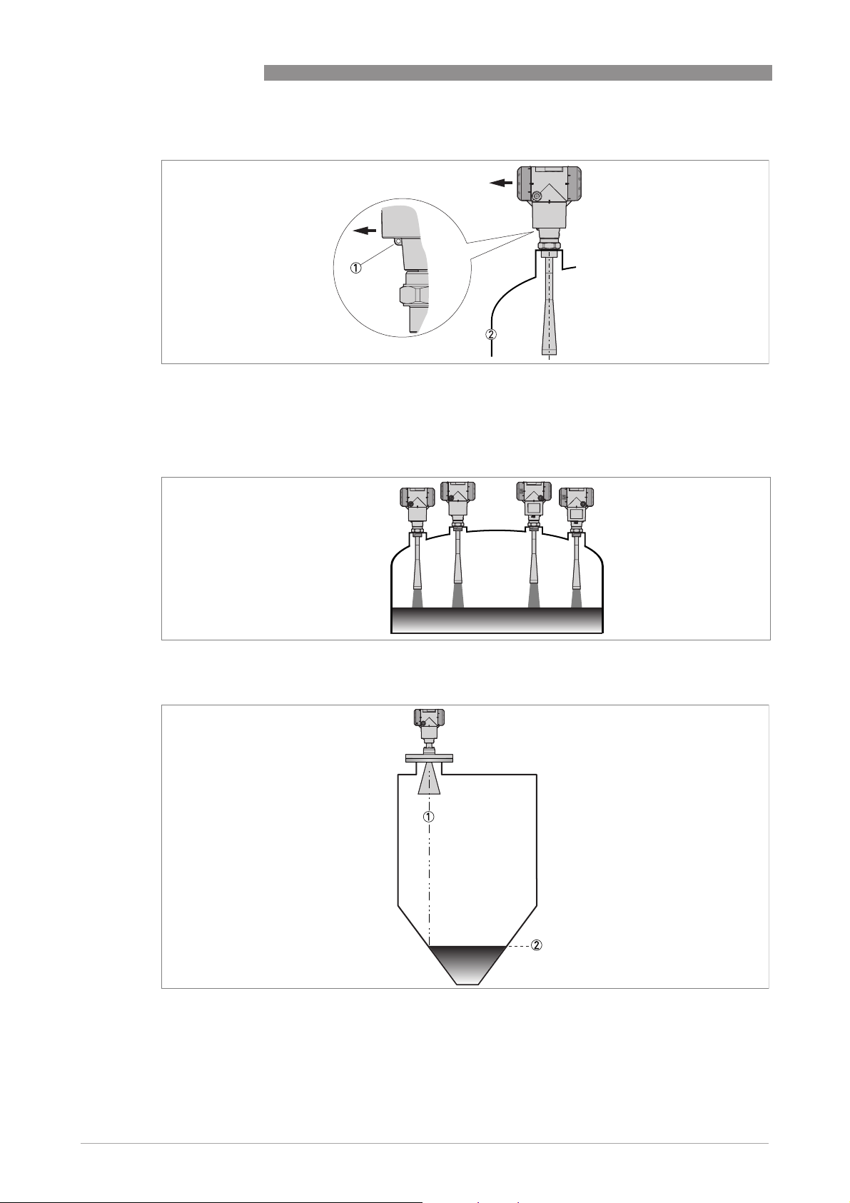
Figure 2-10: A maximum of 4 FMCW radar level meters can be operated in a tank
Figure 2-11: Tanks with conical bottoms
Conical bottoms have an effect on the measuring range. The device cannot measure to the bottom of the tank.
1 Axis of radar beam
2 Minimum level reading
10
www.krohne.com 08/2013 - 4001905202 - QS OPTIWAVE 5200 R02 en
Page 11

OPTIWAVE 5200 C/F
2.7.3 Mounting restrictions
CAUTION!
Follow these recommendations to make sure that the device measures correctly. They have an
effect on the performance of the device.
We recommend that you prepare the installation when the tank is empty.
Mounting restrictions: General data
INSTALLATION 2
Figure 2-12: Mounting restrictions: General data
1 Do not tilt the device more than 2°
2 We recommend that you do an empty spectrum recording if there are too many obstacles in the radar beam (refer to
Operation
Operation). If necessary, install a bypass chamber or stilling well or use an "S" antenna extension or a "L" antenna
OperationOperation
extension (the device must be installed on the side of the tank) to move the device away from obstacles.
3 5mm/ 0.2¨ max. for high-dielectric constant liquids
4 Beam radius (DN80 (3¨) Metallic Horn antenna): increments of 290 mm/m or 3.4¨/ft (16°)
Beam radius (DN100 (4¨) Metallic Horn antenna): increments of 210 mm/m or 2.6¨/ft (12°)
Beam radius (DN150 (6¨) Metallic Horn antenna): increments of 140 mm/m or 1.7¨/ft (8°)
Beam radius (DN200 (8¨) Metallic Horn antenna): increments of 100 mm/m or 1.3¨/ft (6°)
Beam radius (PP Wave Horn and PTFE Wave Horn antenna): increments of 176 mm/m or 2.1¨/ft (10°)
www.krohne.com08/2013 - 4001905202 - QS OPTIWAVE 5200 R02 en
11
Page 12

2 INSTALLATION
Obstacles in the tank
Figure 2-13: Obstacles in the tank
Do not put the device directly above obstacles (agitator, support beams, heating tubes etc.). Parasitic signals from obstacles will cause the device to measure incorrectly.
1 Solution 1: Put the device on another process connection away from obstacles
2 Solution 2: Use the same process connection, but also use an "S" extension
3 Solution 3: Attach the device to the side of the tank and use an "L" (right angle) extension
OPTIWAVE 5200 C/F
CAUTION!
Do not put the device near to the product inlet. If the product that enters the tank touches the
antenna, the device will measure incorrectly. If the product fills the tank directly below the
antenna, the device will also measure incorrectly.
Figure 2-14: Product inlets
1 The device is in the correct position.
2 The device is too near to the product inlet.
12
www.krohne.com 08/2013 - 4001905202 - QS OPTIWAVE 5200 R02 en
Page 13

OPTIWAVE 5200 C/F
Devices with Metallic Horn antenna
Figure 2-15: Devices with Metallic Horn antenna
1 If the roof is not flat, the antenna must project out of the nozzle
2 Short tank nozzle
3 Long tank nozzle (device with an antenna extension)
4 If the roof is flat and the tank fitting is symmetrical, it is not necessary for the antenna to project out of the nozzle.
Thus, the device can have a larger measuring range.
INSTALLATION 2
The antenna must project out of the nozzle. If necessary, use an antenna extension. But if the
tank roof is flat and the tank fitting is symmetrical, it is not necessary for the antenna to project
out of the nozzle. Thus, the device can have a larger measuring range.
Devices with PTFE or PP Wave Horn antenna
Figure 2-16: Devices with PTFE or PP Wave Horn antenna
Recommended height of tank process connection, a = 44...200 mm / 1.7...7.87¨
1 Device with a PTFE Wave Horn antenna and a flange connection. There are antenna extension options available
(100 mm / 4¨, 200 mm / 8¨ and 300 mm / 12¨) for long nozzles.
2 Device with a PP Wave Horn antenna and a thread connection
CAUTION!
If there are parasitic signals, the device will not measure correctly. Parasitic signals are caused
by:
•
Objects in the tank.
•
Sharp corners that are perpendicular to the path of the radar beam.
•
Sudden changes in tank diameter in the path of the radar beam.
Do an Empty Spectrum recording (refer to Operation
www.krohne.com08/2013 - 4001905202 - QS OPTIWAVE 5200 R02 en
Operation) to remove parasitic signals with a filter.
OperationOperation
13
Page 14

2 INSTALLATION
Requirements for flange connections
Figure 2-17: Flange connection
Equipment needed:
• Device
• Flange gasket (not supplied)
• Wrench (not supplied)
• Make sure the flange on the nozzle is level.
• Make sure that you use the applicable gasket for the flange dimensions and the process.
• Align the gasket correctly on the flange facing of the nozzle.
• Lower the antenna carefully into the tank.
• Make sure that you point the device in the correct direction. Refer to "Point the device in the
correct direction" in this section.
• Tighten the flange bolts.
i Refer to local rules and regulations for the correct torque to apply to the bolts.
OPTIWAVE 5200 C/F
14
www.krohne.com 08/2013 - 4001905202 - QS OPTIWAVE 5200 R02 en
Page 15

OPTIWAVE 5200 C/F
Requirements for threaded connections
Figure 2-18: Threaded connection
Equipment needed:
• Device
• Gasket for G 1½ connection (not supplied)
• Thread seal tape (PTFE) for 1½ NPT connection (not supplied)
• 50 mm / 2¨ wrench (not supplied)
INSTALLATION 2
WARNING!
Do not tighten the connection to a torque more than 40 Nm. If the connection is too tight, this will
damage the thread.
To prevent damage to the antenna, make sure that the minimum diameter of the hole for a
½
NPT thread connection is not less than 43.4 mm / 1.71¨.
1
• Make sure the tank connection is level.
• ISO 228-1 (G) connection:
ISO 228-1 (G) connection: Make sure that you use the applicable gasket for the connection
ISO 228-1 (G) connection:ISO 228-1 (G) connection:
dimensions and the process.
• ISO 228-1 (G) connection:
ISO 228-1 (G) connection: Align the gasket correctly.
ISO 228-1 (G) connection:ISO 228-1 (G) connection:
• NPT connection:
NPT connection: Wind the thread seal tape around the process connection in agreement with
NPT connection:NPT connection:
good engineering practice.
• Lower the antenna carefully into the tank.
• Turn the threaded connection on the antenna to attach the device to the process connection.
• Make sure that you point the device in the correct direction. Refer to "Point the device in the
correct direction" in this section.
• Tighten the connection to the correct torque (not more than 40 Nm).
www.krohne.com08/2013 - 4001905202 - QS OPTIWAVE 5200 R02 en
15
Page 16

2 INSTALLATION
2.7.4 Standpipes (stilling wells and bypass chambers)
Use a standpipe if:
• There is highly conductive foam in the tank.
• The liquid is very turbulent or agitated.
• There are too many other objects in the tank.
• The device is measuring a liquid (petro-chemicals) in a tank with a floating roof.
• The device is installed in a horizontal cylindrical tank (refer to the end of this section)
For more data, refer to the Handbook.
OPTIWAVE 5200 C/F
Figure 2-19: Installation recommendations for standpipes (stilling wells and bypass chambers)
1 A stilling well solution
2 A bypass chamber solution
3 Air circulation hole
4 Level of the liquid
2.7.5 Wall support for the remote version
Figure 2-20: Wall support for the remote version (attached to the remote converter)
16
www.krohne.com 08/2013 - 4001905202 - QS OPTIWAVE 5200 R02 en
Page 17

OPTIWAVE 5200 C/F
1 Use marks on the wall to help you put the wall support in the correct position. For more data,
refer to "Dimensions and Weights" in the handbook.
2 Use equipement and tools that agree with health and safety regulations and good engineering
practice.
3 Make sure the wall support is correctly attached to the wall.
INSTALLATION 2
2.7.6 How to attach an antenna extension (Metallic Horn or Wave Guide antennas)
CAUTION!
IF THE ANTENNA EXTENSION IS SUPPLIED WITH THE DEVICE AS AN OPTION:
If the antenna extension is attached to the device, no more work is necessary.
If the antenna extension is not attached to the device, refer to Procedure 1 in this section. It is not
necessary to change the device settings. The manufacturer sets the related menu items to the
correct values in the factory.
IF THE ANTENNA EXTENSION IS SUPPLIED AFTER DELIVERY OF THE DEVICE (SPARE PART):
You must attach the antenna extension to the device and change the device settings in the
SUPERVISOR menu. If you have a straight antenna extension, refer to Procedures 1 and 2A. If you
have an "S" or "L" (right-angle) antenna extension, refer to Procedures 1 and 2B.
DANGER!
If you installed the device on the tank before the procedure, make the device safe (de-energize
the circuit, clean the device etc.) before you continue the work.
Equipment needed
Figure 2-21: Equipment needed
1 Device (with a Metallic Horn or Wave Guide antenna option only)
2 Antenna extension. From left to right: straight, "S" and "L" (right-angle) extension.
3 10 mm open-end or box-end wrench (not supplied)
4 3 hex head screws M6×25-A4-70 (supplied in a plastic sachet)
Obey the assembly procedure that follows:
www.krohne.com08/2013 - 4001905202 - QS OPTIWAVE 5200 R02 en
17
Page 18

2 INSTALLATION
OPTIWAVE 5200 C/F
Figure 2-22: Procedure: How to attach an antenna extension
WARNING!
Make sure that you do not damage the PTFE cone when you remove or install the antenna.
Procedure 1: How to attach an antenna extension
1 Remove the 3 hex head screws from the antenna with the 10 mm wrench.
2 Remove the antenna. Make sure that you do not damage the PTFE cone when you remove the
antenna.
3 Attach the antenna extension below the flange. Make sure that the antenna extension is fully
engaged. Make sure that you do not damage the PTFE cone when you attach the antenna extension.
4 Attach 3 hex head screws to the antenna extension with a 10 mm wrench. Tighten the screws
to a torque of 8 Nm.
5 Attach the antenna below the antenna extension.
6 Attach 3 hex head screws to the antenna with a 10 mm wrench. Tighten the screws to a torque
of 8 Nm.
i If the antenna extension is supplied with the device, it is not necessary to change the device
settings. End of the procedure.
7 If the antenna extension is supplied after delivery of the device, it is necessary to change the
device settings. Make a selection from one of the procedures (2A or 2B) that follow: straight
18
www.krohne.com 08/2013 - 4001905202 - QS OPTIWAVE 5200 R02 en
Page 19

OPTIWAVE 5200 C/F
antenna extension, "S" antenna extension or "L" (right angle) antenna extension.
Procedure 2A: Device settings for a device with a straight antenna extension
• Enter the SUPERVISOR menu (2.0.0).
• Push [>>>>], 2 × [], [>>>>] and 6 × [] to go to menu item ANTENNA EXTENSION (2.3.7).
• Push [>>>>] to change the value. Push [>>>>] to change the position of the cursor. Push [] to
decrease the value or [] to increase the value.
i If the antenna extension has a length of 500 mm, enter the value "500" (if units for this
menu item are in mm).
• Push 3 × [^^^^] to go back to the "STORE" screen.
• Push [] or [] to set the screen to STORE YES
i End of the procedure.
Procedure 2A: Device settings for a device with an "S" or L" (right angle) antenna
extension
• Enter the SUPERVISOR menu (2.0.0).
• Push [>>>>], 2 × [], [>>>>] and 6 × [] to go to menu item ANTENNA EXTENSION (2.3.7).
• Push [>>>>] to change the value. Push [>>>>] to change the position of the cursor. Push [] to
decrease the value or [] to increase the value.
i If units are in mm, enter the value "243" (for an "S" extension) or "236" (for an "L"
extension).
• Push [^^^^] to go back to the menu. Push 2 × [] to go to menu item DIST.PIECE (2.3.9).
• Push [>>>>] to change the value. Push [>>>>] to change the position of the cursor. Push [] to
decrease the value or [] to increase the value.
i If units are in mm, enter the value "221" (for an "S" extension) or "236" (for an "L"
extension).
• Push 3 × [^^^^] to go back to the "STORE" screen.
• Push [] or [] to set the screen to STORE YES
i End of the procedure.
STORE YES and push [^^^^].
STORE YESSTORE YES
STORE YES and push [^^^^].
STORE YESSTORE YES
INSTALLATION 2
Settings for devices with antenna extensions in mm
Antenna extension type Device settings
ANTENNA EXTENSION (2.3.7) DIST.PIECE (2.3.9)
Straight
"S" 243 221 2
"L" (right angle) 236 236 2
1 This value depends on the length of the antenna extension. Enter the length of the antenna extension: 100, 200, 300,
400, 500 or 1000 mm
2 If the device has a high temperature extension, add 120 mm to this value
1
2.7.7 How to turn or remove the signal converter
The converter turns 360°, but we recommend that the tag hole on the housing points to the
nearest tank wall. For more data, refer to
converter can be removed from the process connection assembly under process conditions.
Recommended mounting position
0 2
on page 9. The
www.krohne.com08/2013 - 4001905202 - QS OPTIWAVE 5200 R02 en
19
Page 20

2 INSTALLATION
OPTIWAVE 5200 C/F
Figure 2-23: How to turn or remove the signal converter
1 Tool: 5 mm Allen wrench (not supplied) for the lock screw on the signal converter
2 Cover for the wave guide hole on top of the process connection assembly (not supplied)
CAUTION!
Do not loosen the 4 socket head screws on the process connection assembly.
If you remove the housing, put a cover on the the wave guide hole on top of the process
connection assembly. Make sure that the wave guide hole is clean and dry.
When the housing is attached to the process connection assembly, tighten the lock screw with
the 5 mm Allen wrench 1.
2.7.8 How to attach the weather protection to the device
The device and the weather protection option are supplied disassambled in the same box. You
must attach the weather protection when you install the device.
20
Figure 2-24: Equipment needed
1 Device
2 Weather protection (option).
3 2 butterfly screws and spring washers. The manufacturer attaches these parts to the device before delivery.
www.krohne.com 08/2013 - 4001905202 - QS OPTIWAVE 5200 R02 en
Page 21

OPTIWAVE 5200 C/F
INSTALLATION 2
Figure 2-25: Installation of the weather protection (general procedure)
1 Remove the 2 butterfly screws from the housing. Make sure that spring washer is attached
correctly to the housing (on the weather protection fixture).
2 Lower the weather protection onto the device.
3 Attach the 2 butterfly screws. Make sure that you use the correct holes to attach the weather
protection. The holes must agree with the housing option used (compact vertical (non-Ex or
Ex i-approved etc.)). For more data, refer to the illustration that follows:
www.krohne.com08/2013 - 4001905202 - QS OPTIWAVE 5200 R02 en
21
Page 22

2 INSTALLATION
OPTIWAVE 5200 C/F
Figure 2-26: Holes for installation of the weather protection (housing versions)
1 Compact horizontal housing (non-Ex and Ex i-approved devices)
2 Compact horizontal housing (Ex d-approved devices)
3 Compact vertical housing (non-Ex and Ex i-approved devices)
4 Compact vertical housing (Ex d-approved devices)
The overall dimensions of the weather protection are in "Dimensions and weight" in the
handbook.
22
www.krohne.com 08/2013 - 4001905202 - QS OPTIWAVE 5200 R02 en
Page 23

OPTIWAVE 5200 C/F
2.7.9 How to open the weather protection
INSTALLATION 2
Figure 2-27: How to open the weather protection
1 Loosen the bolt on each side of the weather protection.
2 Pull the sides of the weather protection out of the notch for the closed position.
3 Pull the weather protection up and back.
i This will open the weather protection.
4 Tighten the bolts to lock the weather protection in its open position.
www.krohne.com08/2013 - 4001905202 - QS OPTIWAVE 5200 R02 en
23
Page 24

3 ELECTRICAL CONNECTIONS
3.1 Electrical installation: 2-wire, loop-powered
3.1.1 Compact version
Terminals for electrical installation
Figure 3-1: Terminals for electrical installation
1 Grounding terminal in the housing (if the electrical cable is shielded)
2 Current output -
3 Current output +
4 Location of the external grounding terminal (at the bottom of the converter)
OPTIWAVE 5200 C/F
INFORMATION!
Electrical power to the output terminal energizes the device. The output terminal is also used for
®
HART
communication.
CAUTION!
•
Use the applicable electrical cables with the cable glands.
•
Make sure that the power supply does not have a current more than 5 A or that there is 5 Arated fuse in the electrical circuit that energizes the device.
•
Make sure that the polarity of the power supply is correct. If the polarity is incorrect, you will
not cause damage to the device but the device will not operate.
Open the terminal compartment cover
24
Figure 3-2: How to open the terminal compartment cover
www.krohne.com 08/2013 - 4001905202 - QS OPTIWAVE 5200 R02 en
Page 25

OPTIWAVE 5200 C/F
• Loosen the lock screw with a 2.5 mm Allen wrench.
• Turn the cover counterclockwise with a strap wrench.
• Remove the cover.
Figure 3-3: Procedure for electrical installation
ELECTRICAL CONNECTIONS 3
Equipment needed:
• Small slotted tip screwdriver (not supplied)
Procedure:
1 Do not disconnect the safety cord from the terminal compartment cover. Put the terminal
compartment cover adjacent to the housing.
2 Remove the connector from the circuit board.
3 Connect the electrical wires to the connector. Attach the connector to the circuit board. Tight-
en the cable entry glands.
Close the terminal compartment cover
Figure 3-4: How to close the terminal compartment cover
• Put the cover on the housing and push it down.
• Turn the cover clockwise until it is fully engaged.
• Tighten the lock screw.
www.krohne.com08/2013 - 4001905202 - QS OPTIWAVE 5200 R02 en
25
Page 26

3 ELECTRICAL CONNECTIONS
3.1.2 Remote version
Terminals for electrical installation
Figure 3-5: Terminals for electrical installation
1 Grounding terminal in the housing (if the electrical cable is shielded)
2 Current output -
3 Current output +
4 Location of the external grounding terminal (on the wall support)
OPTIWAVE 5200 C/F
INFORMATION!
Electrical power to the output terminal energizes the device. The output terminal is also used for
®
HART
communication.
CAUTION!
•
Use the applicable electrical cables with the cable glands.
•
Make sure that the power supply does not have a current more than 5 A or that there is 5 Arated fuse in the electrical circuit that energizes the device.
•
Make sure that the polarity of the power supply is correct. If the polarity is incorrect, you will
not cause damage to the device but the device will not operate.
Connections between the remote converter and the antenna housing
26
Figure 3-6: Connections between the remote converter and the antenna housing
1 Remote coverter
2 Antenna housing
3 Power supply: voltage in -
4 Power supply: voltage in +
5 Signal cable B
6 Signal cable A
7 Shielding wire (attached to Faston connectors in the housings of the remote converter and the antenna housing)
www.krohne.com 08/2013 - 4001905202 - QS OPTIWAVE 5200 R02 en
Page 27

OPTIWAVE 5200 C/F
ELECTRICAL CONNECTIONS 3
For more electrical installation data, refer to
For more data about the communication cable between the remote converter and the antenna
housing, refer to the handbook.
3.2 Non-Ex devices
Figure 3-7: Electrical connections for non-Ex devices
1 Power supply
2 Resistor for HART
3 Optional connection to the grounding terminal
4 Output: 12...30 VDC for an output of 22 mA at the terminal
5 Device
®
communication
Compact version
on page 24.
3.3 Devices for hazardous locations
DANGER!
For electrical data for device operation in hazardous locations, refer to the related certificates of
compliance and supplementary instructions (ATEX, IECEx, cFMus, ...). You can find this
documentation on the DVD-ROM delivered with the device or it can be downloaded free of charge
from the website (Download Center).
www.krohne.com08/2013 - 4001905202 - QS OPTIWAVE 5200 R02 en
27
Page 28

3 ELECTRICAL CONNECTIONS
3.4 Minimum power supply voltage
Use these graphs to find the minimum power supply voltage for a given current output load.
Non-Ex and Hazardous Location approved (Ex i / IS) devices
1000
900
800
700
600
500
400
300
200
100
OPTIWAVE 5200 C/F
0
12 13 14 15 16 17 18 19 20 21 22 23 24 25 26 27 28 29 30 31 32 33 34 35 36
Figure 3-8: Minimum power supply voltage for an output of 22 mA at the terminal (Non-Ex and Hazardous Location
approval (Ex i / IS))
X: Power supply U [VDC]
Y: Current output load R
L
[Ω]
Hazardous Location (Ex d / XP/NI) approved devices
28
Figure 3-9: Minimum power supply voltage for an output of 22 mA at the terminal (Hazardous Location approval (Ex d /
XP/NI))
X: Power supply U [VDC]
Y: Current output load R
L
[Ω]
www.krohne.com 08/2013 - 4001905202 - QS OPTIWAVE 5200 R02 en
Page 29

OPTIWAVE 5200 C/F
3.5 Protection category
INFORMATION!
The device fulfills all requirements per protection category IP 66/67. It also fulfils all
requirements per NEMA type 4X (housing) and type 6P (antenna).
DANGER!
Make sure that the cable gland is watertight.
ELECTRICAL CONNECTIONS 3
Figure 3-10: How to make the installation agree with protection category IP 67
• Make sure that the gaskets are not damaged.
• Make sure that the electrical cables are not damaged.
• Make sure that the electrical cables agree with the national electrical code.
• The cables are in a loop in front of the device 1 so water does not go into the housing.
• Tighten the cable feedthroughs 2.
• Close unused cable feedthroughs with dummy plugs 3.
The diameter of the outer sheath of the electrical cable and must be 6…10 mm or 0.2…0.39¨.
www.krohne.com08/2013 - 4001905202 - QS OPTIWAVE 5200 R02 en
29
Page 30

3 ELECTRICAL CONNECTIONS
3.6 Networks
3.6.1 General information
The device uses the HART® communication protocol. This protocol agrees with the HART®
Communication Foundation standard. The device can be connected point-to-point. It can also
operate in a multi-drop network of up to 15 devices.
The device output is factory-set to communicate point-to-point. To change the communication
mode from point-to-point
3.6.2 Point-to-point connection
point-to-point to multi-drop
point-to-pointpoint-to-point
multi-drop, refer to "Network configuration" in the handbook.
multi-dropmulti-drop
OPTIWAVE 5200 C/F
Figure 3-11: Point-to-point connection (non-Ex)
1 Address of the device (0 for point-to-point connection)
2 4...20 mA + HART
3 Resistor for HART® communication
4 Power supply
5 HART
6 HART
®
converter
®
communication software
®
30
www.krohne.com 08/2013 - 4001905202 - QS OPTIWAVE 5200 R02 en
Page 31

OPTIWAVE 5200 C/F
3.6.3 Multi-drop networks
ELECTRICAL CONNECTIONS 3
Figure 3-12: Multi-drop network (non-Ex)
1 Address of the device (each device must have a different address in multidrop networks)
2 4mA + HART
3 Resistor for HART® communication
4 Power supply
5 HART
6 HART
®
®
converter
®
communication software
www.krohne.com08/2013 - 4001905202 - QS OPTIWAVE 5200 R02 en
31
Page 32

3 ELECTRICAL CONNECTIONS
3.6.4 Fieldbus networks
INFORMATION!
Fieldbus options are available for the compact version of the device.
For more data, refer to the supplementary instructions for FOUNDATION™ fieldbus and
PROFIBUS PA.
FOUNDATION™ fieldbus network (non-Ex)
OPTIWAVE 5200 C/F
Figure 3-13: FOUNDATION™ fieldbus network (non-Ex)
1 Field device
2 Junction box
3 H1 network
4 H1/HSE converter
5 High Speed Ethernet (HSE)
6 Workstation
32
www.krohne.com 08/2013 - 4001905202 - QS OPTIWAVE 5200 R02 en
Page 33

OPTIWAVE 5200 C/F
PROFIBUS PA/DP network (non-Ex)
ELECTRICAL CONNECTIONS 3
Figure 3-14: PROFIBUS PA/DP network (non-Ex)
1 Field device
2 Bus termination
3 PROFIBUS PA bus segment
4 Segment coupler (PA/DP link)
5 PROFIBUS DP bus line
6 Control system (PLC / Class 1 master device)
7 Engineering or operator workstation (Control tool / Class 2 master device)
www.krohne.com08/2013 - 4001905202 - QS OPTIWAVE 5200 R02 en
33
Page 34

4 OPERATION
4.1 General notes
For more data about device configuration, refer to the handbook.
4.2 Digital display screen
4.2.1 Local display screen layout
OPTIWAVE 5200 C/F
Figure 4-1: Local display screen layout in Normal mode
1 Current output percentage (bar graph and text — only shown if the current output function is the same as the mea-
surement on the screen in normal mode)
2 Measurement type (in this example, distance)
3 Device status (NE 107 symbols)
4 Device tag name
5 Updated measurement data symbol (the symbol flashes each time the measurement data is updated)
6 Measurement value and units
7 Device status (markers)
8 Keypad buttons (refer to the table in the section that follows)
4.2.2 Functions of keypad buttons
Keypad button Function
[Right]
[Return / Escape]
[Down]
[Up]
1 If you have made a strapping table in menu item 2.8.1 INPUT TABLE for volume or mass measurement, "Conversion"
and "Ullage Conv." will be shown in the list of measurement types
Normal mode:
Normal mode: Enter Information menu (Enter Configuration mode)
Normal mode:Normal mode:
Configuration mode:
Configuration mode: Move cursor to the right
Configuration mode:Configuration mode:
Normal mode:
Normal mode: Change units (m, cm, mm, in, ft)
Normal mode:Normal mode:
Configuration mode:
Configuration mode: Exit
Configuration mode:Configuration mode:
Normal mode:
Normal mode: Change measurement type (distance, level , output (%),
Normal mode:Normal mode:
output (mA), conversion, ullage conversion, reflection) 1
Configuration mode:
Configuration mode: Decrease value or change parameter
Configuration mode:Configuration mode:
Normal mode:
Normal mode: Change measurement type (distance, level , output (%),
Normal mode:Normal mode:
output (mA), conversion, ullage conversion, reflection) 1
Configuration mode:
Configuration mode: Increase value or change parameter
Configuration mode:Configuration mode:
34
For data on keypad functions, refer to the Operation
Operation section in the Handbook.
OperationOperation
www.krohne.com 08/2013 - 4001905202 - QS OPTIWAVE 5200 R02 en
Page 35

OPTIWAVE 5200 C/F
4.3 Quick Setup (Parameters)
Use this procedure to change the tank height, tank type, output function, output range and give
the top and bottom measuring limits. « xx » in the illustrations shows that you can change the
value or the parameter. Push the keypad buttons in the correct sequence:
Procedure
Screen Steps Description
• [>
>], [] and [>>>>]. Default screen.
>>
• [>
>], [^^^^], [], [], [>>>>] and [^^^^]. Enter the password (the default password
>>
OPERATION 4
Enter configuration mode (2.0.0
SUPERVISOR).
is shown). If it is necessary to change the
password, refer to the handbook.
• 2× [>
• [>
• [>
• [
• [^
• [
• [^
>] Push this button to start the quick set-up
>>
>] to change the tank height (H).
>>
>] to change the position of the cursor.
>>
] to decrease the value or [] to
increase the value.
^] to confirm.
^^
] or [] for the selection of the
conditions in which the device is used
(Storage, Process, Agitator).
^] to confirm.
^^
procedure.
The distance from the flange face / thread
stop of the tank connection down to the
tank bottom. If the tank has a dish-shaped
or conical bottom, the tank height is
measured to a point on the tank bottom
directly below the antenna.
If the surface of the product is flat, select
"Storage". If the surface of the product is
disturbed, select "Process". If the surface
of the product is agitated with vortexes and
foam, select "Agitator".
• [
] or [] for the selection of the
measurement name (Distance, Level,
Conversion, Ullage Conv. or Reflection).
• [^
^] to confirm.
^^
www.krohne.com08/2013 - 4001905202 - QS OPTIWAVE 5200 R02 en
The manufacturer sets the output function
to “Level” before delivery.
If it is necessary to measure volume,
ullage volume, mass or ullage mass
(Conversion or Ullage Conv.), refer to the
handbook.
35
Page 36

4 OPERATION
Screen Steps Description
• [
] or [] for the selection of the current
output range (4-20 mA/3.6E, 4-20, 3.8-
20.5/3.6E, etc.).
• [^
^] to confirm.
^^
• [>
>] to change Scale 4 mA.
>>
• [>
>] to change the position of the cursor.
>>
• [
] to decrease the value or [] to
increase the value.
• [^
^] to confirm.
^^
OPTIWAVE 5200 C/F
Use this step to give the 4 mA output
setting (0% limit) in the tank. Refer to the
illustrations that follow. Illustration 1
shows the settings for level. Illustration 2
shows the settings for distance.
• [>
>] to change Scale 20 mA.
>>
• [>
>] to change the position of the cursor.
>>
• [
] to decrease the value or [] to
increase the value.
• [^
^] to confirm.
^^
• [
] or [] for the selection of the error
delay (0 s, 10 s, 20 s, 30 s, 1 mn, 2 mn,
5mn or 15mn).
• [^
^] to confirm.
^^
• [>
>] to change the tag name.
>>
• [>
>] to change the position of the cursor.
>>
• [
] to decrease the alphanumeric value
(A, B, ..., 1, 2, ...) or [] to increase the
alphanumeric value.
• [^
^] to confirm.
^^
• 2× [^
• [
• [^
^] to confirm.
^^
] or [] for the selection of the save
option (STORE NO or STORE YES).
^] to confirm.
^^
Use this step to give the 20 mA output
setting (100% limit) in the tank. Refer to
the illustrations that follow. Illustration 1
shows the settings for level. Illustration 2
shows the settings for distance.
The time after which the current output
changes to an error value. The error value
shows that there is a measurement error.
The device has an identification code (tag
name). The supervisor can enter a
maximum of 8 numbers or letters.
Set to STORE YES to save and use the data.
Set to STORE NO to cancel the changes to
the device settings.
36
www.krohne.com 08/2013 - 4001905202 - QS OPTIWAVE 5200 R02 en
Page 37

OPTIWAVE 5200 C/F
NOTES 5
www.krohne.com08/2013 - 4001905202 - QS OPTIWAVE 5200 R02 en
37
Page 38

5 NOTES
OPTIWAVE 5200 C/F
38
www.krohne.com 08/2013 - 4001905202 - QS OPTIWAVE 5200 R02 en
Page 39

OPTIWAVE 5200 C/F
NOTES 5
www.krohne.com08/2013 - 4001905202 - QS OPTIWAVE 5200 R02 en
39
Page 40

KROHNE product overview
• Electromagnetic flowmeters
• Variable area flowmeters
• Ultrasonic flowmeters
• Mass flowmeters
• Vortex flowmeters
• Flow controllers
• Level meters
• Temperature meters
• Pressure meters
• Analysis products
• Products and systems for the oil & gas industry
• Measuring systems for the marine industry
Head Office KROHNE Messtechnik GmbH
Ludwig-Krohne-Str. 5
47058 Duisburg (Germany)
Tel.:+49 (0)203 301 0
Fax:+49 (0)203 301 10389
info@krohne.de
The current list of all KROHNE contacts and addresses can be found at:
© KROHNE 08/2013 - 4001905202 - QS OPTIWAVE 5200 R02 en - Subject to change without notice.
www.krohne.com
 Loading...