

Page 1
Handbook
Handbook
PIPEPATROL
PIPEPATROL
PIPEPATROLPIPEPATROL
Leak detection and localisation system
HandbookHandbook
© KROHNE 02/2013 - 4002275001 - MA PipePatrol R01 en
Page 2

: IMPRINT :::::::::::::::::::::::::::::::::::::::
All rights reserved. It is prohibited to reproduce this documentation, or any part thereof, without
the prior written authorisation of KROHNE Messtechnik GmbH.
Subject to change without notice.
Copyright 2013 by
KROHNE Messtechnik GmbH - Ludwig-Krohne-Str. 5 - 47058 Duisburg (Germany)
2
www.krohne.com 02/2013 - 4002275001 - MA PipePatrol R01 en
Page 3

PIPEPATROL
CONTENTS
1 Safety instructions 5
1.1 Intended use ..................................................................................................................... 5
1.2 Safety instructions from the manufacturer ..................................................................... 5
1.2.1 Copyright and data protection ................................................................................................ 5
1.2.2 Disclaimer ............................................................................................................................... 5
1.2.3 Product liability and warranty ................................................................................................ 6
1.2.4 Information concerning the documentation........................................................................... 6
1.2.5 Warnings and symbols used................................................................................................... 7
1.3 Safety instructions for the operator................................................................................. 7
2 Device description 8
2.1 Functionality ..................................................................................................................... 8
2.2 Hardware installation....................................................................................................... 8
2.3 Principle of Extended Real Time Transient Model (E-RTTM).......................................... 9
2.4 Leak localisation method ............................................................................................... 10
3 Operation 12
3.1 General safety notes.......................................................................................................12
3.2 Start-up........................................................................................................................... 13
3.3 Layout of user interface ................................................................................................. 13
3.3.1 Status window ....................................................................................................................... 14
3.3.2 Controls................................................................................................................................. 17
3.3.3 Operator windows ................................................................................................................. 17
3.3.4 Main Overview ....................................................................................................................... 18
3.3.5 Pipeline Overview.................................................................................................................. 20
3.3.6 Trend ..................................................................................................................................... 21
3.4 Detailed description of leak detection screens ............................................................. 24
3.4.1 Leak information................................................................................................................... 24
3.4.2 Events.................................................................................................................................... 26
3.4.3 Alarm history......................................................................................................................... 29
3.4.4 Explanation (Legend) ............................................................................................................ 30
3.5 Leak alarm handling ...................................................................................................... 31
3.6 LDS system commands.................................................................................................. 36
3.6.1 Stop and start the LDS.......................................................................................................... 36
3.6.2 Application alarm.................................................................................................................. 37
3.7 Messages and error handling ........................................................................................ 38
3.7.1 List of event messages ......................................................................................................... 38
3.7.2 List of alarm messages ........................................................................................................ 41
3.7.3 Troubleshooting .................................................................................................................... 42
3.8 Expert functions on Operator Station ............................................................................ 43
3.8.1 User settings......................................................................................................................... 43
3.8.2 Default passwords ................................................................................................................ 43
www.krohne.com02/2013 - 4002275001 - MA PipePatrol R01 en
3
Page 4

CONTENTS
PIPEPATROL
4 Service 44
4.1 Maintenance on the hardware ....................................................................................... 44
4.1.1 Filters .................................................................................................................................... 44
4.1.2 Mechanical damages ............................................................................................................ 44
4.2 Availability of services .................................................................................................... 44
5 Notes 45
4
www.krohne.com 02/2013 - 4002275001 - MA PipePatrol R01 en
Page 5

PIPEPATROL
1.1 Intended use
PipePatrol is a leak detection and localisation system for liquid and gas pipelines which operates
in the stand-alone mode without any human interaction. It can be used during pumping, rampup, ramp-down, shut in and standstill conditions and allows continuous montitoring during all
operating conditions. Additionally functionalities are the batch tracking and the instrument error
analysis.
1.2 Safety instructions from the manufacturer
1.2.1 Copyright and data protection
The contents of this document have been created with great care. Nevertheless, we provide no
guarantee that the contents are correct, complete or up-to-date.
The contents and works in this document are subject to copyright. Contributions from third
parties are identified as such. Reproduction, processing, dissemination and any type of use
beyond what is permitted under copyright requires written authorisation from the respective
author and/or the manufacturer.
SAFETY INSTRUCTIONS 1
The manufacturer tries always to observe the copyrights of others, and to draw on works created
in-house or works in the public domain.
The collection of personal data (such as names, street addresses or e-mail addresses) in the
manufacturer's documents is always on a voluntary basis whenever possible. Whenever
feasible, it is always possible to make use of the offerings and services without providing any
personal data.
We draw your attention to the fact that data transmission over the Internet (e.g. when
communicating by e-mail) may involve gaps in security. It is not possible to protect such data
completely against access by third parties.
We hereby expressly prohibit the use of the contact data published as part of our duty to publish
an imprint for the purpose of sending us any advertising or informational materials that we have
not expressly requested.
1.2.2 Disclaimer
The manufacturer will not be liable for any damage of any kind by using its product, including,
but not limited to direct, indirect or incidental and consequential damages.
This disclaimer does not apply in case the manufacturer has acted on purpose or with gross
negligence. In the event any applicable law does not allow such limitations on implied warranties
or the exclusion of limitation of certain damages, you may, if such law applies to you, not be
subject to some or all of the above disclaimer, exclusions or limitations.
Any product purchased from the manufacturer is warranted in accordance with the relevant
product documentation and our Terms and Conditions of Sale.
The manufacturer reserves the right to alter the content of its documents, including this
disclaimer in any way, at any time, for any reason, without prior notification, and will not be liable
in any way for possible consequences of such changes.
www.krohne.com02/2013 - 4002275001 - MA PipePatrol R01 en
5
Page 6

1 SAFETY INSTRUCTIONS
1.2.3 Product liability and warranty
The operator shall bear responsibility for the suitability of the device for the specific purpose.
The manufacturer accepts no liability for the consequences of misuse by the operator. Improper
installation and operation of the devices (systems) will cause the warranty to be void. The
respective "Standard Terms and Conditions" which form the basis for the sales contract shall
also apply.
1.2.4 Information concerning the documentation
To prevent any injury to the user or damage to the device it is essential that you read the
information in this document and observe applicable national standards, safety requirements
and accident prevention regulations.
If this document is not in your native language and if you have any problems understanding the
text, we advise you to contact your local office for assistance. The manufacturer can not accept
responsibility for any damage or injury caused by misunderstanding of the information in this
document.
This document is provided to help you establish operating conditions, which will permit safe and
efficient use of this device. Special considerations and precautions are also described in the
document, which appear in the form of underneath icons.
PIPEPATROL
6
www.krohne.com 02/2013 - 4002275001 - MA PipePatrol R01 en
Page 7
PIPEPATROL
1.2.5 Warnings and symbols used
Safety warnings are indicated by the following symbols.
DANGER!
This information refers to the immediate danger when working with electricity.
DANGER!
This warning refers to the immediate danger of burns caused by heat or hot surfaces.
DANGER!
This warning refers to the immediate danger when using this device in a hazardous atmosphere.
DANGER!
These warnings must be observed without fail. Even partial disregard of this warning can lead to
serious health problems and even death. There is also the risk of seriously damaging the device
or parts of the operator's plant.
SAFETY INSTRUCTIONS 1
WARNING!
Disregarding this safety warning, even if only in part, poses the risk of serious health problems.
There is also the risk of damaging the device or parts of the operator's plant.
CAUTION!
Disregarding these instructions can result in damage to the device or to parts of the operator's
plant.
INFORMATION!
These instructions contain important information for the handling of the device.
LEGAL NOTICE!
This note contains information on statutory directives and standards.
• HANDLING
HANDLING
HANDLINGHANDLING
This symbol designates all instructions for actions to be carried out by the operator in the
specified sequence.
i RESULT
RESULT
RESULTRESULT
This symbol refers to all important consequences of the previous actions.
1.3 Safety instructions for the operator
WARNING!
In general, devices from the manufacturer may only be installed, commissioned, operated and
maintained by properly trained and authorized personnel.
This document is provided to help you establish operating conditions, which will permit safe and
efficient use of this device.
www.krohne.com02/2013 - 4002275001 - MA PipePatrol R01 en
7
Page 8

2 DEVICE DESCRIPTION
2.1 Functionality
INFORMATION!
For detailed overview about the system architecture please refer to the "Functional Design
Specification (FDS)" of the project.
The PipePatrol leak detection system (LDS) station will be configured to provide the following
main features:
Monitoring Station (LDS server)
• Leak detection and localisation in pumping and standstill conditions
• Calculation of the leak rate
• Calculation of the leak location
• Remote maintenance via a remote access gateway (if connection is available)
• Alarming
• Data logging and event reporting
• Storing of reports and other data
PIPEPATROL
Operator Station (LDS client)
• Visualisation of the running leak detection system
• Alarming (visual and acoustic)
• Trending
• Event logging
• Controlling & operating functions
2.2 Hardware installation
The Monitoring Station (MS) is completely installed before the start-up. No further installation is
required.
8
www.krohne.com 02/2013 - 4002275001 - MA PipePatrol R01 en
Page 9

PIPEPATROL
DEVICE DESCRIPTION 2
2.3 Principle of Extended Real Time Transient Model (E-RTTM)
According to API 1130, leak detection systems can be categorised into external and internal
systems. External systems include acoustic sensors and sensing cables that are placed
alongside the pipeline. Due to the extremely high installation costs the use of external systems is
usually restricted to high risk areas such as nature protection areas and near rivers. Internal
systems are systems that perform leak detection based on measured parameters such as flow,
pressure and temperature.
PipePatrol is an internal system based on E-RTTM (Extended Real Time Transient Model) and
SMB (Statistical Mass Balance).
E-RTTM
E-RTTM
E-RTTME-RTTM
E-RTTM is a combination of RTTM and leak pattern recognition by means of statistical analysis.
The fundamental principle is that RTTM is a series of algorithms that allow calculation of the
flow, based solely on pressure and temperature readings at the inlet and outlet of the pipeline.
To do this RTTM uses the conservation laws for mass, momentum and energy and the
thermodynamic state equations for pressure and enthalpy.
When applying RTTM algorithms, the flow is not only measured by flowmeters but also
calculated from pressure and temperature readings at the inlet and outlet. Subtracting the
calculated flow from the measured flow gives the flow residual. Combining the two flow
residuals gives the true flow residual (inlet minus outlet). The RTTM algorithms compensate for
medium compressibility and line expansion.
Leak pattern recognition
Leak pattern recognition
Leak pattern recognitionLeak pattern recognition
Basically the leak pattern recognition algorithm constantly monitors whether the residual
(difference between inlet and outlet flow after the transient effects have been compensated for
by RTTM) exceed a predefined threshold. If this threshold is exceeded statistical analysis will be
used to determine whether this is caused by a true leak or by a sensor drift.
SMB
SMB
SMBSMB
SMB is a combination of compensated mass balance and leak pattern recognition by means of
statistical analysis.
Compensated mass balance method is based on the equation of conservation of mass. The
result of this equation is permanently passed to the leak pattern recognition, which analyses it
statistical to avoid false alarms.
www.krohne.com02/2013 - 4002275001 - MA PipePatrol R01 en
9
Page 10
2 DEVICE DESCRIPTION
2.4 Leak localisation method
To idendify the source of the leak accuratley the following 3 localisation methods are combined
in PipePatrol.
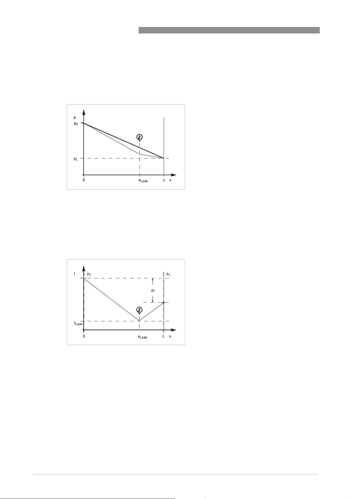
Gradient Intersection Method
Figure 2-1: Gradient Intersection Method
PIPEPATROL
Under zero leak conditions, pressure drops uniformly along the pipeline. When a leak occurs,
more liquid or gas flows through the pipeline before the leak than after it.
The pressure gradient along the pipeline therefore changes at the leak. The leak localisation can
thus be identified at the point where the gradient changes.
Wave Propagation Method
Figure 2-2: Wave Propagation Method
A sudden leak will cause a negative pressure wave in the pipeline, simply because gas or liquid is
leaking out. This pressure wave will travel through the pipeline at the sound velocity of gas or
liquid.
10
Depending on the localisation of the leak, the pressure wave will arrive at one end of the pipeline
before it arrives at the other. The leak position can be calculated from the difference in the
arrival times at the inlet and outlet.
www.krohne.com 02/2013 - 4002275001 - MA PipePatrol R01 en
Page 11
PIPEPATROL
DEVICE DESCRIPTION 2
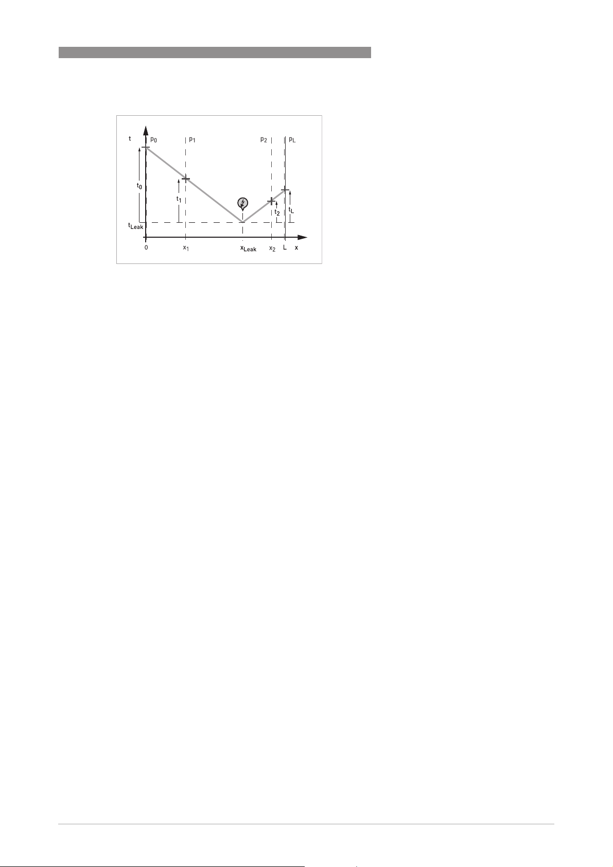
Extended Wave Propagation Method
Figure 2-3: Extended Wave Propagation Method
Using the same physical principle as the wave propagation method, the extended method takes
into account intermediate station measurements. Using the information from intermediate
stations and E-RTTM's knowledge about the velocity of sound profile in the pipeline, jitter error
introduced by slow sensor scan rates can be eliminated.
www.krohne.com02/2013 - 4002275001 - MA PipePatrol R01 en
11
Page 12
3 OPERATION
3.1 General safety notes
DANGER!
This system operates on 230 VAC, 50/60 Hz. This current can cause serious injuries or death.
WARNING!
•
None of the system components should be opened, unless by trained and certified electrical
engineers.
•
Damaged or interrupted electrical cables between the PC and the rest of the system, as well
as terminated or damaged software, can lead to a failure in the leak detection system.
•
The PCs must be properly grounded and cannot be used in an Ex area.
INFORMATION!
•
Before shutting down (one of the) PCs all running software application should be closed in a
normal way.
•
The instructions mentioned in manuals from subsuppliers should be followed.
•
Each operator must know the functionality of all functions that are accessible for this
operator.
PIPEPATROL
12
www.krohne.com 02/2013 - 4002275001 - MA PipePatrol R01 en
Page 13

PIPEPATROL
3.2 Start-up
The LDS software is automatically loaded after the monitoring station has been switched on. The
software automatically starts to record measurement data and reaches its operational state
shortly after start-up.
For the correct operation of the system, the following items should be considered:
• An uninterrupted power supply is required. Power supply variations can lead to re-starting of
the computer and in the worst case cause the PC to crash.
• The data communication between monitoring station and the metering system must be
running in order for the system to receive measurement data.
3.3 Layout of user interface
The main screen is the interface between the user and the leak detection system. The menu
layout and the different windows are shown in the following drawing.
OPERATION 3
Figure 3-1: Layout of user interface
1 Status window
2 Operator window
3 Controls
www.krohne.com02/2013 - 4002275001 - MA PipePatrol R01 en
13
Page 14
3 OPERATION
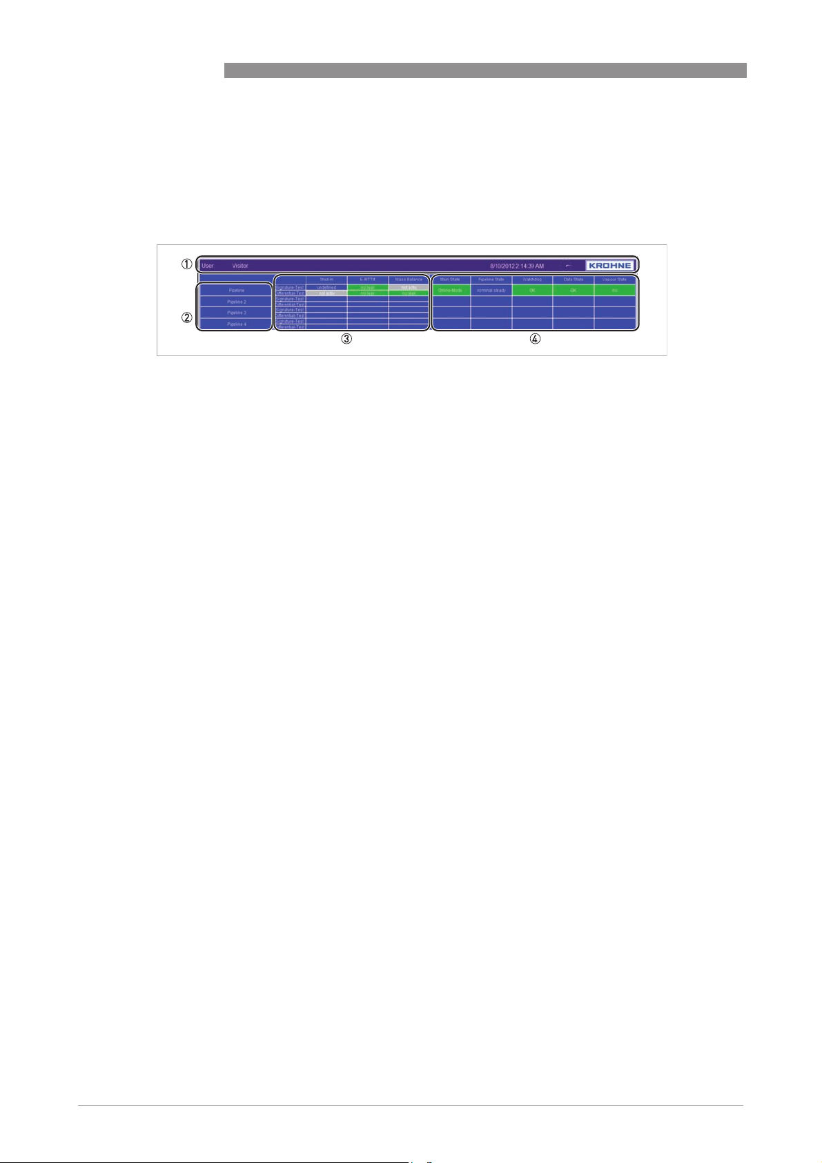
3.3.1 Status window
The status window shows main information of each applicable system, which is available on each
screen of the PipePatrol HMI. The functionality of each information is explained in the following
part.
1 General error information from the operator station
General error information from the operator station
General error information from the operator stationGeneral error information from the operator station
The operator station is the PC where the actual HMI is running.
The following information can be shown:
• Name of the user who is logged in
• Date and time of the operator station machine
• Error OPC Connection (red/flashing)
The connection to the OPC server of the leak detection software is lost.
2 Name of the leak detection system
Name of the leak detection system
Name of the leak detection systemName of the leak detection system
The operator station HMI is designed to be able to monitor several running leak detection systems
which are designated by a unique system name. A click on one of the systems, switches the operator
screen to the leak information of the selected leak detection system.
3 Alarm information of the running leak detection
Alarm information of the running leak detection
Alarm information of the running leak detectionAlarm information of the running leak detection
The system performs leak detection by using different modules. Each module provides alarm
information by Signature-Test and Differential-Test. The usage of these modules depends on the
actual running conditions of the pipeline.
• Shut-In:
Shut-In: This module is performing an analysis of the pressure reading inside the closed pipe
Shut-In:Shut-In:
section. As long one of the reading is available it will perform leak detection for standstill
conditions.
• E-RTTM:
E-RTTM: This module indicates the model based leak detection. It will be activated as long flow,
E-RTTM:E-RTTM:
pressure and temperature readings are available.
• Mass Balance:
Mass Balance: This module offers a statistical analysis of the inlet and outlet flow. As long both
Mass Balance:Mass Balance:
readings are available it will provide leak detection in pumping conditions.
• Following additional modules, following the same operating philosophy, may be available:
- Virtual Flow
- Substation Monitoring
The following information can be shown:
• Undefined (blue):
Undefined (blue): LDS is not running; no leak information is available.
Undefined (blue):Undefined (blue):
• Unknown (blue):
Unknown (blue): LDS is starting-up; leak information will be available soon.
Unknown (blue):Unknown (blue):
• No leak (green):
No leak (green): The system is running; no leak is detected.
No leak (green):No leak (green):
• Leak Alarm (red flushing):
Leak Alarm (red flushing): The system is up and running and a leak has been detected.
Leak Alarm (red flushing):Leak Alarm (red flushing):
• Acknowledge alarm (blue):
Acknowledge alarm (blue): An alarm has been detected and confirmed by a logged operator.
Acknowledge alarm (blue):Acknowledge alarm (blue):
4 States information of the running leak detection
States information of the running leak detection
States information of the running leak detectionStates information of the running leak detection
The following state information are available:
• Main State:
Main State: Indication of the main systems states.
Main State:Main State:
• Pipeline State:
Pipeline State: Indication of the actual pipeline conditions.
Pipeline State:Pipeline State:
• Watchdog:
Watchdog: Indication of the actual status of the watchdog monitoring.
Watchdog:Watchdog:
• Data State:
Data State: Indication of the actual status of data gathering.
Data State:Data State:
• Indication of the status of vapour monitoring along the line.
PIPEPATROL
14
For detailed information refer to the following details.
www.krohne.com 02/2013 - 4002275001 - MA PipePatrol R01 en
Page 15

PIPEPATROL
OPERATION 3
Main State
Main State
Main StateMain State
A click on the "Main State" box of a system enables the change of the actual state.
The following information can be shown:
• Undefined (blue):
Undefined (blue): The system is not running; no system information is available.
Undefined (blue):Undefined (blue):
• Stopped (red):
Stopped (red): The system is stopped. The recording of data is still running.
Stopped (red):Stopped (red):
• Online-Mode (green):
Online-Mode (green): The system is running by using the current measured pipeline data.
Online-Mode (green):Online-Mode (green):
• Self Test-Mode (yellow):
Self Test-Mode (yellow): The system is running by using the recorded pipeline data.
Self Test-Mode (yellow):Self Test-Mode (yellow):
• Tuning-Mode (blue):
Tuning-Mode (blue): Maintenance activities are carried out on the monitoring station.
Tuning-Mode (blue):Tuning-Mode (blue):
Therefore the leak detection is stopped at the moment.
• Application alarm (red):
Application alarm (red): An internal error of the leak detection software has been detected.
Application alarm (red):Application alarm (red):
System stopped working. A logged operator has to reset the alarm and to restart the system.
If the failure occurs several times please contact our support.
• Error (red):
Error (red): The application is not running correctly.
Error (red):Error (red):
Pipeline State
Pipeline State
Pipeline StatePipeline State
The following information can be shown:
• Undefined (blue):
Undefined (blue): The system is not running; no information is available.
Undefined (blue):Undefined (blue):
• Unknown (blue):
Unknown (blue): The system is filling up the internal FIFOs. There is not enough information
Unknown (blue):Unknown (blue):
available to estimate the pipeline conditions (possible after a restart of the system). The
information will be available soon.
• Shut-In (blue):
Shut-In (blue): The pipeline is running in shut-in conditions. Valves at the inlet and at the
Shut-In (blue):Shut-In (blue):
outlet are closed.
• Multi Shut-in (blue):
Multi Shut-in (blue): All valves are closed.
Multi Shut-in (blue):Multi Shut-in (blue):
• Partial Shut-in (blue):
Partial Shut-in (blue): At least one section is closed.
Partial Shut-in (blue):Partial Shut-in (blue):
• Blocked Line (blue):
Blocked Line (blue): Minimum one valve is closed, either at the inlet or at the outlet.
Blocked Line (blue):Blocked Line (blue):
• Standstill (blue):
Standstill (blue): No flow conditions along the line. The flow readings are below a predefined
Standstill (blue):Standstill (blue):
value. Valves at the inlet and at the outlet are opened.
• Start-Up (blue):
Start-Up (blue): The pipeline start-up with pumping operations. The flow readings are above a
Start-Up (blue):Start-Up (blue):
predefined value.
• Shutdown (blue):
Shutdown (blue): The pumping operations stopped.
Shutdown (blue):Shutdown (blue):
• Nominal unknown (blue):
Nominal unknown (blue): The pipeline is running in pumping conditions at nominal flow level.
Nominal unknown (blue):Nominal unknown (blue):
The system is filling the internal FIFOs. There is not enough information available to estimate
further exact pipeline conditions (possible after a restart of the system). Further pipeline
information about pipeline conditions will be available soon.
• Nominal high transient (blue):
Nominal high transient (blue): The pipeline is running in pumping conditions at nominal flow
Nominal high transient (blue):Nominal high transient (blue):
level. High transient conditions detected by high variation of flow readings.
Watchdog
Watchdog
WatchdogWatchdog
A click on the "Watchdog" box of one of the systems opens a dialogue windows which is showing
all available counters, monitored by the HMI.
The following information can be shown:
• OK:
OK: The watchdog counter of the system is updated within the timeout range.
OK:OK:
• Alarm (red/flashing):
Alarm (red/flashing): The watchdog counter of the system is not updated and exceeds the
Alarm (red/flashing):Alarm (red/flashing):
timeout range. The system might be not working correctly.
www.krohne.com02/2013 - 4002275001 - MA PipePatrol R01 en
15
Page 16

3 OPERATION
Data State
Data State
Data StateData State
The following information can be shown:
• Undefined:
Undefined: The system is not running; no information is available.
Undefined:Undefined:
• Unknown:
Unknown: The system is filling the internal FIFOs. There is not enough information available
Unknown:Unknown:
to estimate the pipeline conditions (possible after a restart of the system). The information
will be available soon.
• OK (green):
OK (green): All measured data is available.
OK (green):OK (green):
• Warning (yellow):
Warning (yellow): Minimum one measured data is not available. This measurement is not
Warning (yellow):Warning (yellow):
essential for the functionality of the LDS. The system is working by using fall back values.
• Error (red):
Error (red): Minimum one measured data is not available. This measurement is essential for
Error (red):Error (red):
the functionality of the LDS. The system holds functionality until the necessary
measurements are back online.
Vapour State
Vapour State
Vapour StateVapour State
The following information can be shown:
• Undefined:
Undefined: The system is not running; no information is available.
Undefined:Undefined:
• No (green):
No (green): The pressure along the line is above the predefined vapour pressure (product
No (green):No (green):
property).
• Warning (yellow):
Warning (yellow): The pressure along the line is reaching the area of predefined vapour
Warning (yellow):Warning (yellow):
pressure (product property).
• Small (red):
Small (red): The pressure along the line is slightly below the predefined vapour pressure
Small (red):Small (red):
(product property). Small cavitation can be expected.
• Large (red):
Large (red): The pressure along the line is below the predefined vapour pressure (product
Large (red):Large (red):
property). Large cavitation can be expected.
• Error (red):
Error (red): There is not enough information available to estimate the vapour conditions
Error (red):Error (red):
(possible reason is no pressure readings are available).
PIPEPATROL
16
www.krohne.com 02/2013 - 4002275001 - MA PipePatrol R01 en
Page 17

PIPEPATROL
3.3.2 Controls
The control buttons, at the bottom of the screen, enable to switch between different screens. The
offered buttons and their functionality depend on the actual showed screen. The meaning of
them will be explained in detail in the next chapters. The following buttons are available on each
screen:
Figure 3-2: Control buttons
1 Button to switch to last showed screen
2 Events
3 Alarm History
4 Explanation
1 Last showed screen:
2 Shows the event list (for details refer to
3 Shows the alarm history (for details refer to
4 Shows the legend screen (for details refer to
Switch back to the last showed screen.
(After a start-up of the HMI this button has no functionality)
Events
on page 26).
Alarm history
Explanation (Legend)
OPERATION 3
on page 29).
on page 30).
3.3.3 Operator windows
The operator window is the essential part of the PipePatrol HMI. With this screen the operator
can look on the details of each running leak detection system, monitor the behaviour and control
the system. The actual showed information depends on the selected screen.
Description of the offered screen architecture of the HMI
Main Overview
Leak Information
Trends
Pipeline Overview
Trends
Login/Logoff
User Settings
Exit
Events
Alarm History
Explanation
www.krohne.com02/2013 - 4002275001 - MA PipePatrol R01 en
17
Page 18
3 OPERATION
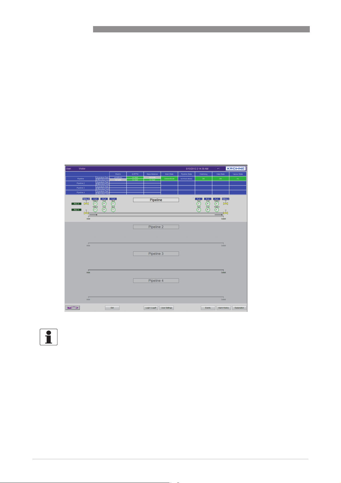
3.3.4 Main Overview
An overview of the most important data for all pipelines is given in the "Main Overview". This
screen is also the start-up screen after a reboot of the station computer.
For each pipeline that is included in the leak detection system, the following information can be
seen:
• Actual volume/mass flow at inlet and outlet
• Actual temperature and pressure at inlet and outlet
• Description of the product at inlet and outlet (multi-product applications only)
• Graphical tracking of batches in the pipeline (for fluids applications only)
PIPEPATROL
18
Figure 3-3: Main Overview screen
INFORMATION!
With a click on one of the available pipelines, the HMI will switch to the particular "Pipeline
Overview" screen (details on page 20
).
www.krohne.com 02/2013 - 4002275001 - MA PipePatrol R01 en
Page 19
PIPEPATROL
OPERATION 3
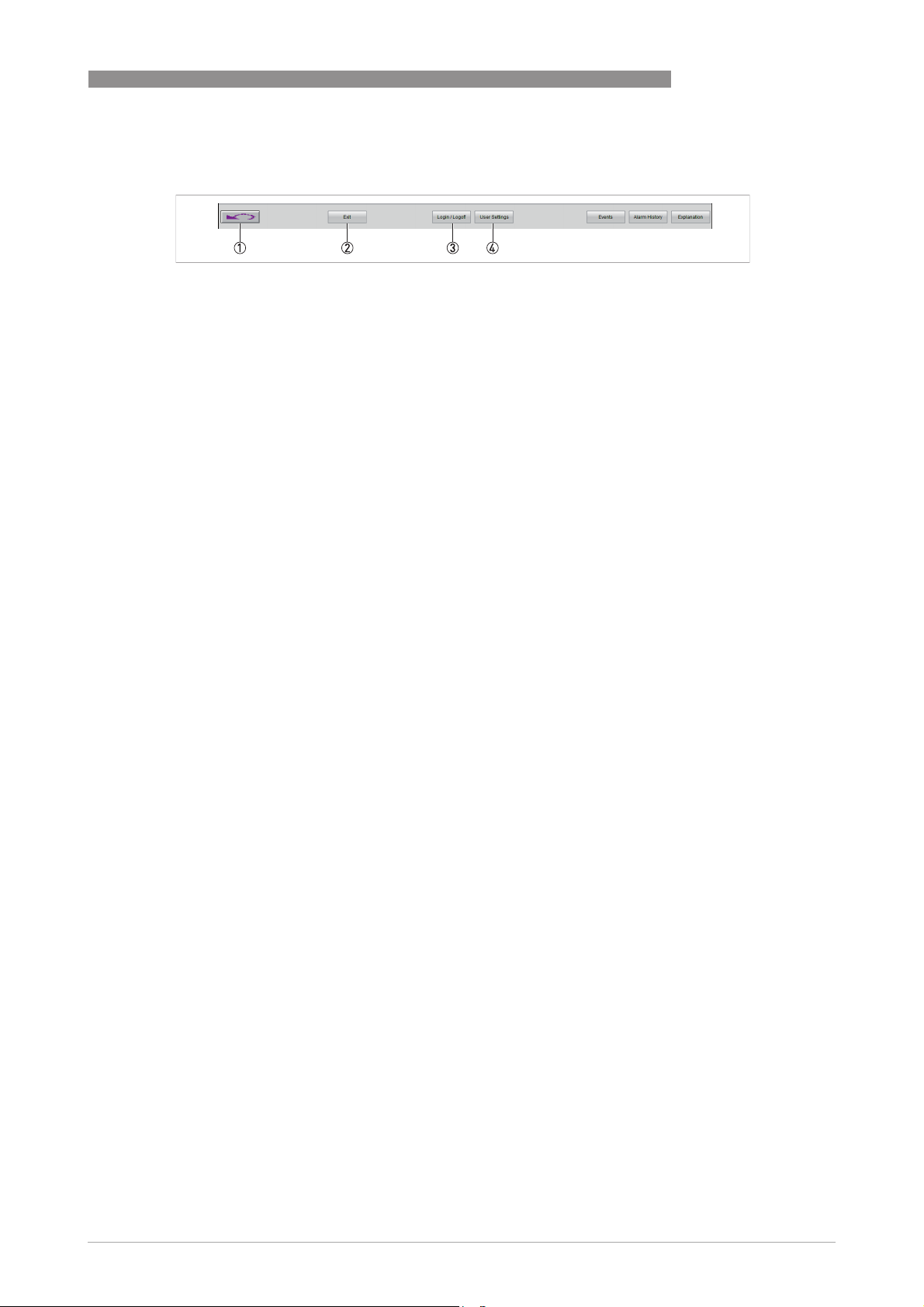
The following controls, at the bottom of the screen, are available on this screen:
1 Last showed screen
Last showed screen
Last showed screenLast showed screen
Switch back to the last showed screen.
(After a start-up of the HMI this button has no functionality)
2 Exit/Shutdown the Operator Station
Exit/Shutdown the Operator Station
Exit/Shutdown the Operator StationExit/Shutdown the Operator Station
Menu to stop the HMI and get back to Windows or to shut down the machine.
3 Login/Logoff
Login/Logoff
Login/LogoffLogin/Logoff
At start-up, the system logs in automatically the visitor account. This account only allows to view the
process data. To get unrestricted access the user has to log in as a specific user. To do this, click on
the "Login/Logoff" button. This button is only available from the "Main Overview" screen.
If the operator is already logged in, the first click logs the account off. A second click on the button
opens a dialogue box with request of login data. With "OK" the system proves the input and grants
access.
The system is delivered with a list of predefined users. That allows the operator crew to log into the
system immediately.
Note:
Note: If the current operator doesn't take any actions for more than 3 minutes, his account will be
Note:Note:
automatically locked.
4 User Settings
User Settings
User SettingsUser Settings
Menu for administration of the HMI user accounts. The details are part of the functional design
specifications (FDS).
www.krohne.com02/2013 - 4002275001 - MA PipePatrol R01 en
19
Page 20
3 OPERATION
3.3.5 Pipeline Overview
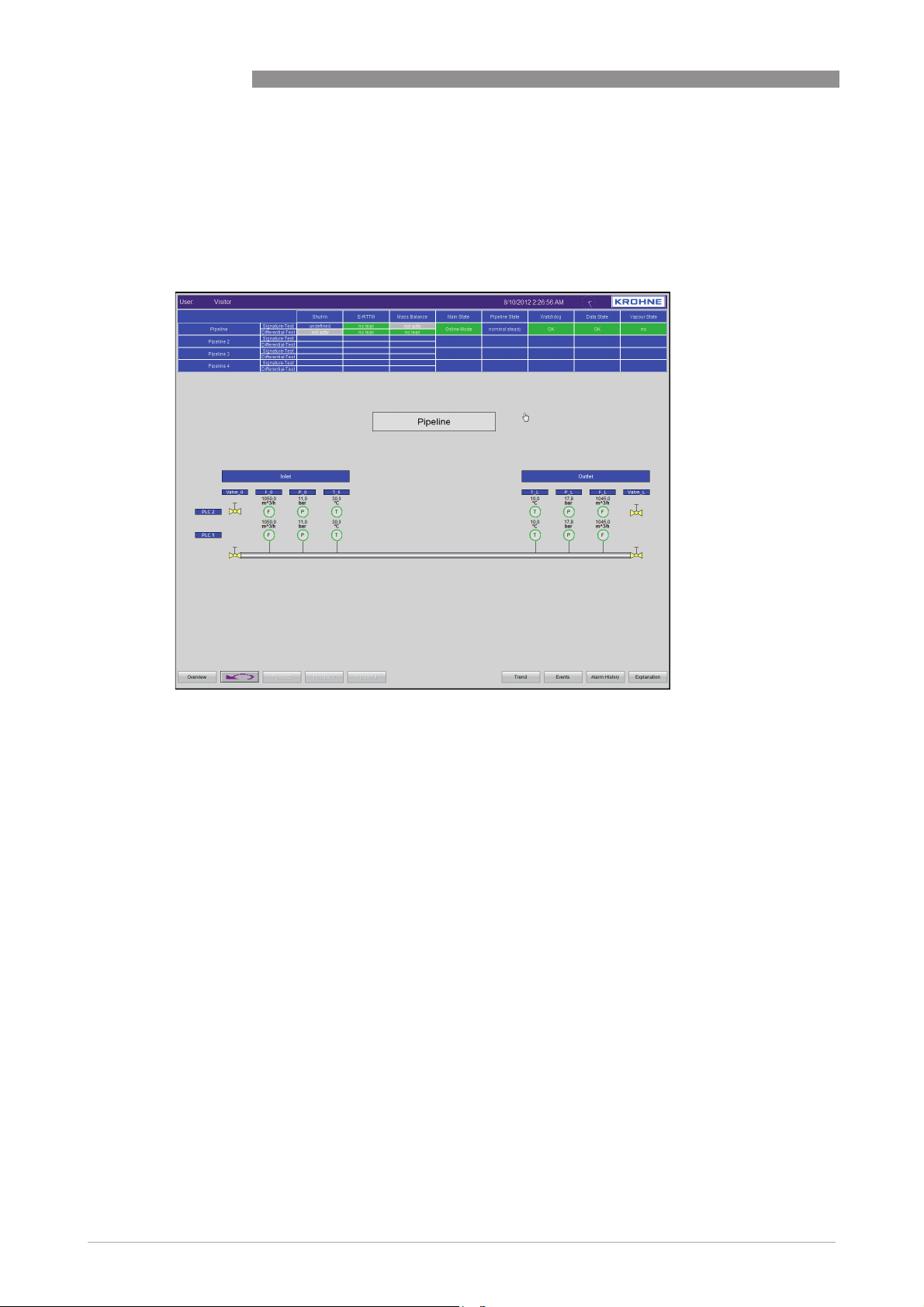
By selecting one of the pipelines showed on the "Main Overview", a detailed overview of this
particular pipeline will be displayed. In this paragraph the pipeline details for pipeline 1 are
described, details are however exactly similar for all pipelines.
PIPEPATROL
Figure 3-4: Example of pipeline details
The following data is shown:
• Actual volume/mass flow at inlet and outlet
• Actual pressure at inlet and outlet
• Actual product temperature at inlet and outlet
• Actual ground temperature at inlet and outlet (optional)
• Actual density at inlet and outlet (optional)
• Actual standardised flow at inlet and outlet (optional)
• Velocity of sound at inlet and outlet (optional)
• Actual measurement data of additional sensors (e.g. intermediate stations, optional)
• Actual state of measurement
- (grey): unknown
- (green): OK
- (red): faulty
• Valves position at inlet and outlet (optional)
- (grey): unknown
- (black): closed
- (yellow): open
- (yellow/grey): moving
- (red): faulty
20
www.krohne.com 02/2013 - 4002275001 - MA PipePatrol R01 en
Page 21
PIPEPATROL
3.3.6 Trend
OPERATION 3
Additional information
Additional information
Additional informationAdditional information
• Batch data at inlet and outlet (optional)
INFORMATION!
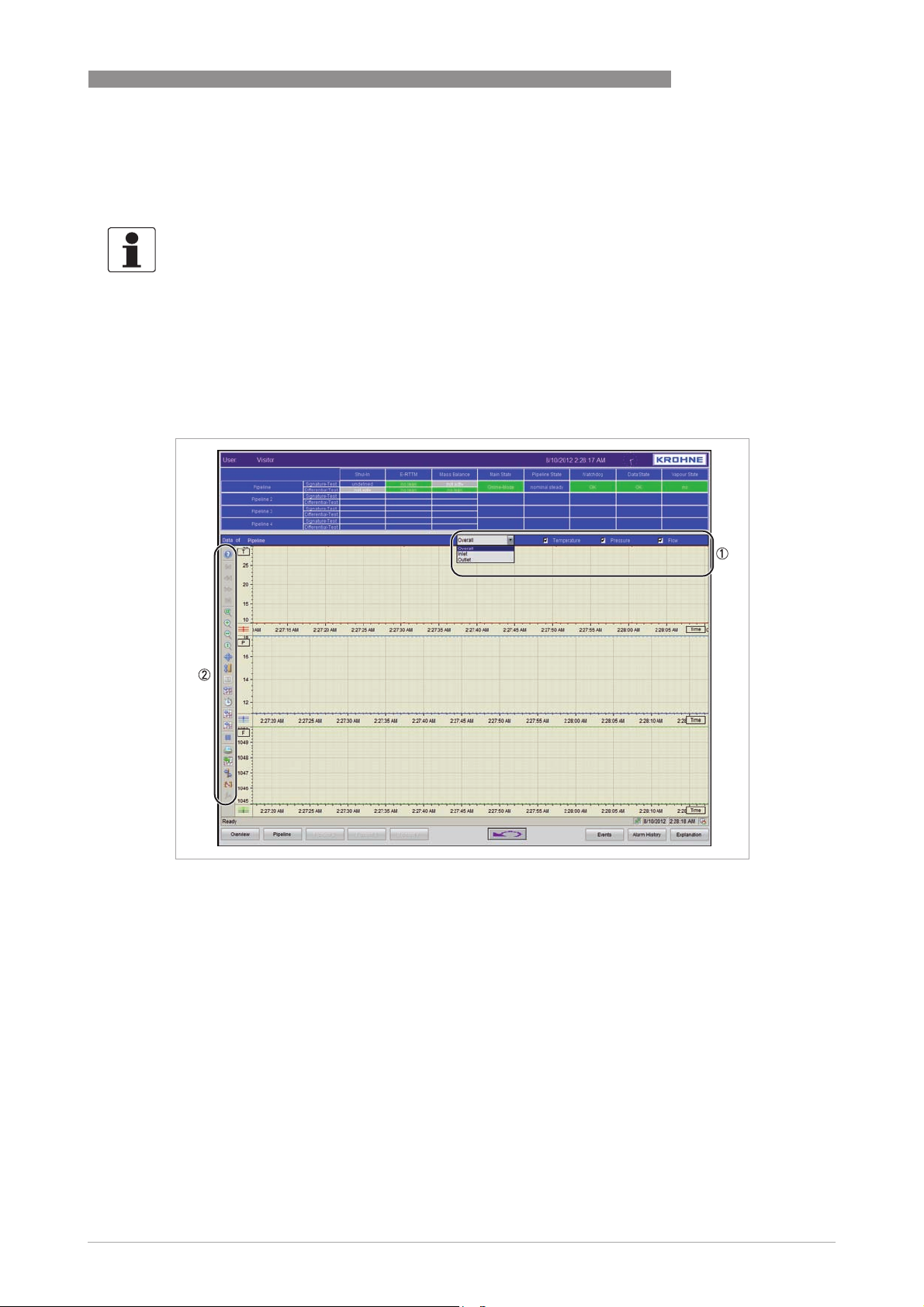
Trending: The screen will switch to trending view.
Trend means the presentation of measurement data in a curve. Using a trend enables to review
the actual measurement data. Since all the measured data is stored on the hard disk, the trend
also allows tracking back historical events.
Figure 3-5: Example of a trend screen
1 Drop down for selection of the type of trend (overall, inlet or outlet)
2 Control boxes for viewing or changing settings
Selection of trends
Selection of trends
Selection of trendsSelection of trends
Use drop down menu and the check boxes from the title of the trend (1) to select which trend
has to be displayed. It is possible either to take a look on the measurements from one station
only (e.g. inlet, outlet or both (overall)) or to select or deselect one or more measurements (e.g.
flow, pressure, temperature etc.).
Trend controls
Trend controls
Trend controlsTrend controls
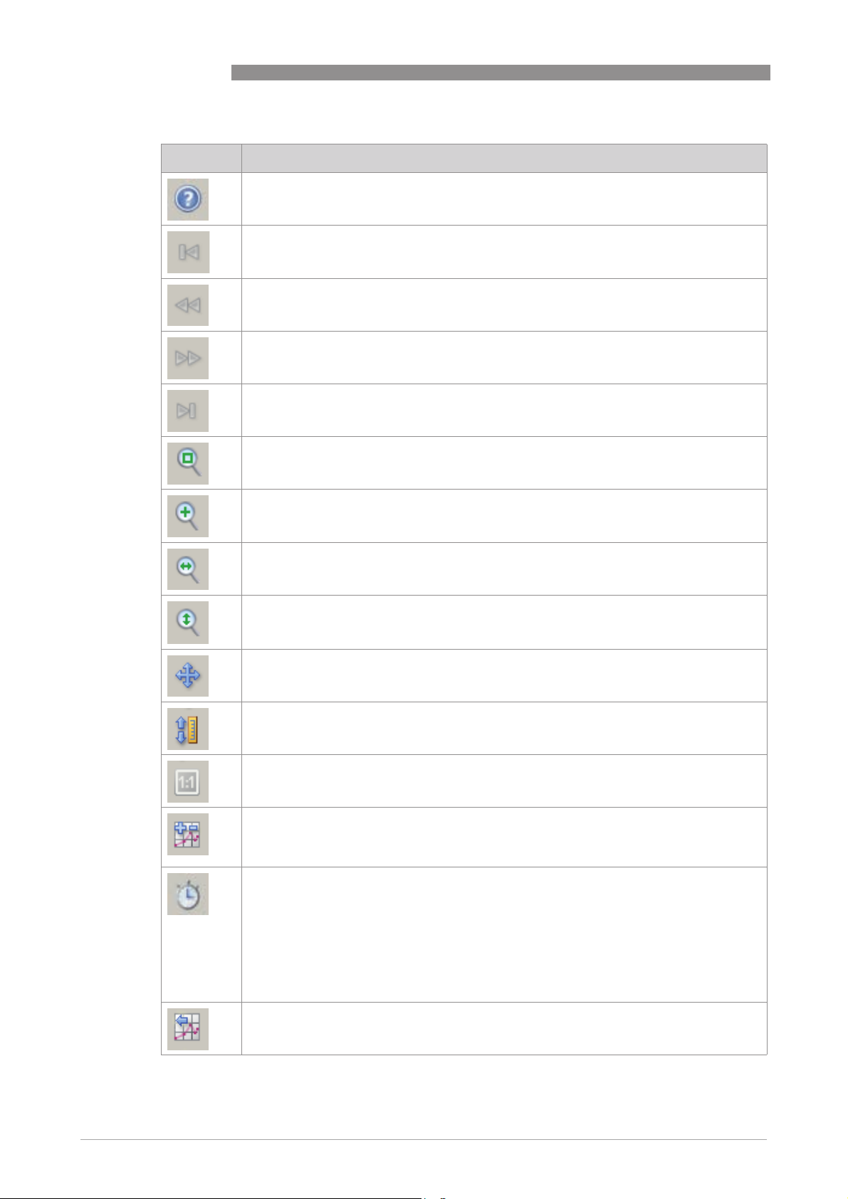
The control boxes (2) enable to change the settings of the trends and to scroll through the
recorded data.
www.krohne.com02/2013 - 4002275001 - MA PipePatrol R01 en
21
Page 22
3 OPERATION
Symbol Description
PIPEPATROL
Help
Help
HelpHelp
Calls up the online help.
First data record
First data record
First data recordFirst data record
Course of a tag within the set time range is displayed. The display starts with the first
archived value.
Previous data record
Previous data record
Previous data recordPrevious data record
Course of a tag within the previous time range is displayed. The display starts with the
currently set time interval.
Next data record
Next data record
Next data recordNext data record
The course of a tag within the next time range is displayed. The display starts with the
currently set time interval.
Last data record
Last data record
Last data recordLast data record
The course of a tag within the set time range is displayed. The display ends with the last
archived value.
Zoom area
Zoom area
Zoom areaZoom area
Enlarge any area of the trend window.
Zoom +/-
Zoom +/-
Zoom +/-Zoom +/Zoom the trend where the cursor mouse is pointing on.
Zoom time axis+/-
Zoom time axis+/-
Zoom time axis+/-Zoom time axis+/Zoom the time axis of the trend where the mouse cursor is pointing on.
Zoom value axis+/-
Zoom value axis+/-
Zoom value axis+/-Zoom value axis+/Zoom the value axis of the trend where the mouse cursor is pointing on.
Move trend range
Move trend range
Move trend rangeMove trend range
Move the selected trend by using the mouse cursor.
Move axis range
Move axis range
Move axis rangeMove axis range
Move the time or value axis of the selected trend by using the mouse cursor.
Original view
Original view
Original viewOriginal view
Return to the configured normal view from an enlarged trend display.
Select trends
Select trends
Select trendsSelect trends
Select or deselect several trends of the trending view. Minimum one trend has to be
selected. With the buttons "Up" and "Down" it is possible to change the order of the
displayed trends.
Select time range
Select time range
Select time rangeSelect time range
Select a time range of the trending view. At minimum one trend has to be selected.
22
Settings:
Settings:
Settings:Settings:
• Trends:
Trends: Select the trend, which time range has to be modified.
Trends:Trends:
• Time range:
Time range: Several options are available to set the time range of the selected trend.
Time range:Time range:
0 - Time range (set the start time and time range)
1 - Start and end time (set the start and end time)
2 - Number of measurement points (set the start and number of measurement points)
Previous trend
Previous trend
Previous trendPrevious trend
The previous trend in the trend view will be marked as the active one.
www.krohne.com 02/2013 - 4002275001 - MA PipePatrol R01 en
Page 23
PIPEPATROL
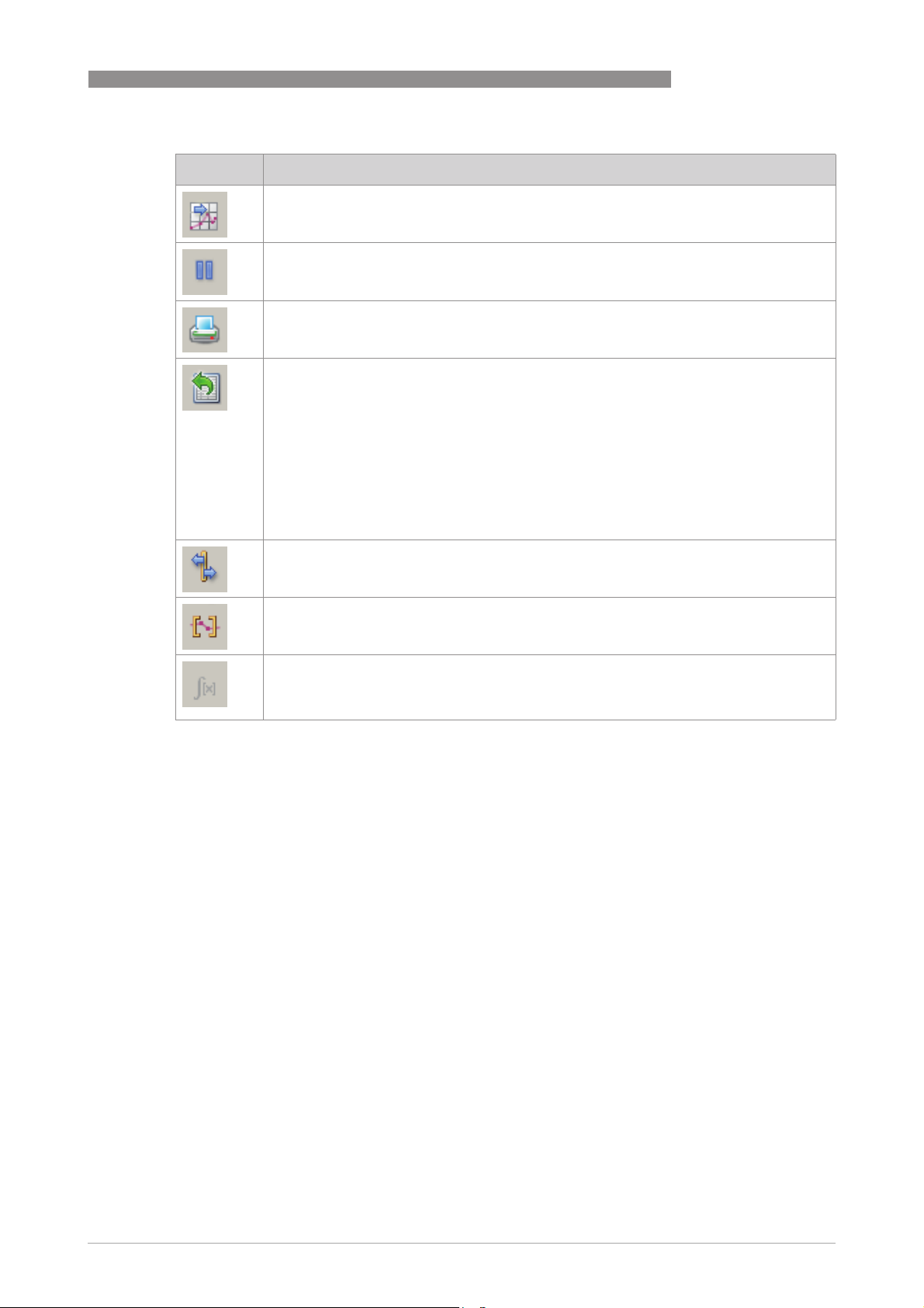
Symbol Description
Next trend
Next trend
Next trendNext trend
The next trend in the trend view will be marked as the active one.
Start/Stop
Start/Stop
Start/StopStart/Stop
Stops the updated display. The values are stored in a clipboard and re-entered after
activating the button again.
Print
Print
PrintPrint
The current view will be printed out, if a printer is connected and configured.
Export data
Export data
Export dataExport data
Export the actual trend to a file.
Settings:
Settings:
Settings:Settings:
• File name and directory:
File name and directory: Select the file name and the folder where the exported data has
File name and directory:File name and directory:
to be stored.
• Scope of data export:
Scope of data export: Select between two options for data export.
Scope of data export:Scope of data export:
0 - All (all data in the trending window will be exported)
1 - Selection (only the selected view will be exported)
• Format:
Format: Only "CSV" available as file extension. A click on the right box enables to set a
Format:Format:
delimiter symbol for the data export.
Ruler
Ruler
RulerRuler
Upright will be showed.
OPERATION 3
Define statistics area
Define statistics area
Define statistics areaDefine statistics area
This button is used to define the time range for calculating the statistics in the trend
window.
Calculate Statistics
Calculate Statistics
Calculate StatisticsCalculate Statistics
The button shows the statistical values in the statistics window. The displayed values refer
to a selected trend with the configured calculation time range. The button is only functional
if a statistics window is connected with the "OnlineTrendControl".
www.krohne.com02/2013 - 4002275001 - MA PipePatrol R01 en
23
Page 24
3 OPERATION
3.4 Detailed description of leak detection screens
3.4.1 Leak information
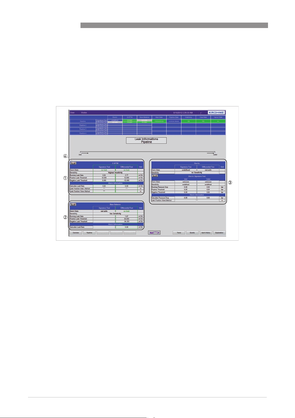
The "Leak Information" screen is showing in details the results which are generated by the leak
detection system. In the standard configuration the information is divided into three parts:
E-RTTM, Mass Balance (or Statistical Flow Balance) and Shut-In leak detection.
PIPEPATROL
Figure 3-6: Example of leak detection screen
1 E-RTTM leak detection
2 Mass Balance leak detection
3 Shut-In leak detection
4 Button to switch to trend view of this module
For each leak detection module the following information are available:
Alarm State
Alarm State
Alarm StateAlarm State
The following information can be shown:
• Undefined (grey):
Undefined (grey): No information available (possible reason: the module is not running).
Undefined (grey):Undefined (grey):
• No leak (green):
No leak (green): Pipeline is running in leak free conditions.
No leak (green):No leak (green):
• Alarm (red):
Alarm (red): Leak detected.
Alarm (red):Alarm (red):
• Alarm acknowledge (red):
Alarm acknowledge (red): A leak alarm has been acknowledge by the operator.
Alarm acknowledge (red):Alarm acknowledge (red):
• Alarm pressure Rising (red):
Alarm pressure Rising (red): A positive pressure wave was detected (only for the Shut-In
Alarm pressure Rising (red):Alarm pressure Rising (red):
module)
• Alarm pressure Drop (red):
Alarm pressure Drop (red): A negative pressure wave was detected (only for the Shut-In
Alarm pressure Drop (red):Alarm pressure Drop (red):
module)
24
www.krohne.com 02/2013 - 4002275001 - MA PipePatrol R01 en
Page 25

PIPEPATROL
OPERATION 3
Sensitivity
Sensitivity
SensitivitySensitivity
The actual sensitivity level of the module under current conditions. The Shut-In module is
showing on the one hand the overall sensitivity of the module, on the other hand it shows the
sensitivity of each monitored pressure transmitter (which can show different sensitivity states).
The following information can be shown:
• Undefined:
Undefined: The module is not running.
Undefined:Undefined:
• No Sensitivity:
No Sensitivity: No sensitivity available.
No Sensitivity:No Sensitivity:
• Lowest Sensitivity
Lowest Sensitivity
Lowest SensitivityLowest Sensitivity
• Low Sensitivity
Low Sensitivity
Low SensitivityLow Sensitivity
• High Sensitivity
High Sensitivity
High SensitivityHigh Sensitivity
• Highest Sensitivity:
Highest Sensitivity: The module is offering the highest available sensitivity.
Highest Sensitivity:Highest Sensitivity:
• Mixed Sensitivity:
Mixed Sensitivity: For the Shut-In module only. The sensitivities of the monitored pressure
Mixed Sensitivity:Mixed Sensitivity:
transmitters are showing different sensitivity states.
Running Leak Rate/Running Pressure Drop
Running Leak Rate/Running Pressure Drop
Running Leak Rate/Running Pressure DropRunning Leak Rate/Running Pressure Drop
For the Signature-Test and Differential-Test of the E-RTTM module, as well as for the Mass
Balance module, it shows the average value of the estimated leak rate in volume or mass flow.
For the Shut-In conditions it shows the average value of the estimated pressure drops.
Pos. and neg. Leak Threshold under current conditions
Pos. and neg. Leak Threshold under current conditions
Pos. and neg. Leak Threshold under current conditionsPos. and neg. Leak Threshold under current conditions
For the Signature-Test and Differential-Test of the E-RTTM module, as well as for the Mass
Balance module, it shows the smallest detectable leak rate. For the Shut-In conditions it shows
the smallest detectable pressure drop.
INFORMATION!
•
In case of an alarm it shows the leak rate and leak location.
•
The provided information of each module are also available as trending view by selecting the
trend button (4) of each module.
www.krohne.com02/2013 - 4002275001 - MA PipePatrol R01 en
25
Page 26
3 OPERATION
3.4.2 Events
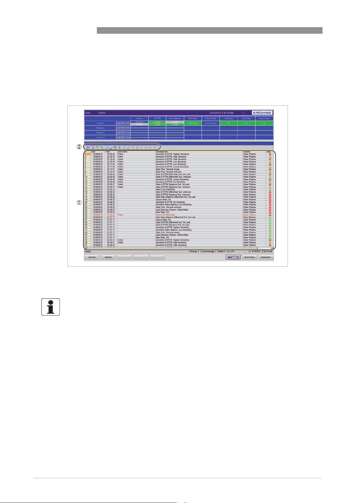
The "Events" screen shows all pending and historical events of the system (e.g. changes in
states, etc.).
PIPEPATROL
Figure 3-7: Example of "Events" screen
1 List of events
2 Control boxes to view and print events
INFORMATION!
Each event will be displayed in a separate line.
The following information will be shown:
• Number
• Date
• Time
• User name (name of the logged user)
• Message
• Pipeline (running LDS will change the states)
• State of the message (green: coming; red: going)
26
www.krohne.com 02/2013 - 4002275001 - MA PipePatrol R01 en
Page 27
PIPEPATROL
OPERATION 3
Event controls
Event controls
Event controlsEvent controls
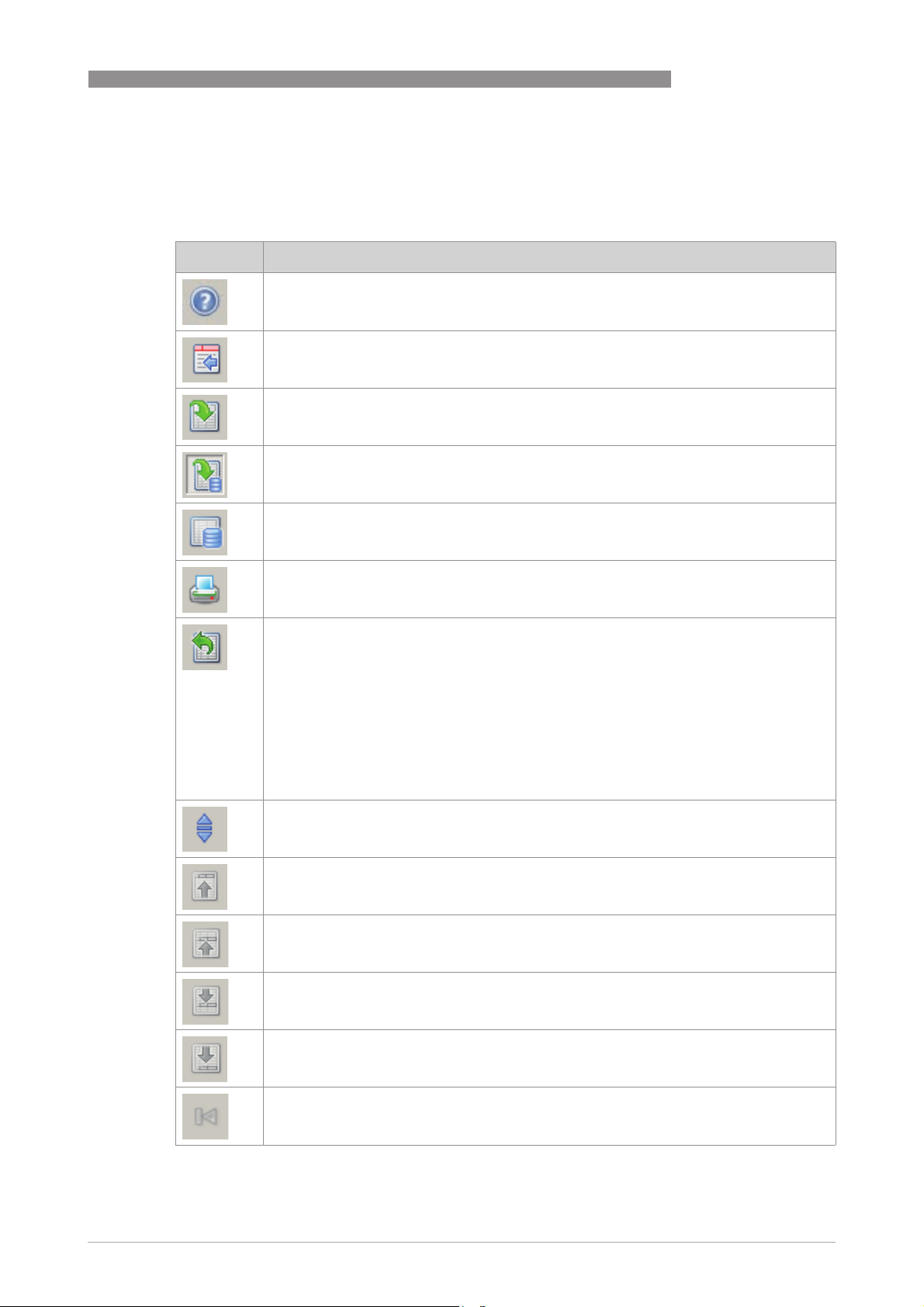
The control boxes, at the left side of the event view, offer the possibility to scroll through the
recorded event data.
Symbol Description
Help
Help
HelpHelp
Calls up the online help.
Configuration dialog
Configuration dialog
Configuration dialogConfiguration dialog
Opens the configuration dialog, in which you can change the properties of the function.
Message list
Message list
Message listMessage list
Shows the actual event list.
Short-term archive list
Short-term archive list
Short-term archive listShort-term archive list
Shows the messages stored in the short-term archive.
Long-term archive list
Long-term archive list
Long-term archive listLong-term archive list
Shows the messages stored in the long-term archive.
Print
Print
PrintPrint
Current view will be printed, if a printer is connected and configured.
Export data
Export data
Export dataExport data
Dialogue box for export of the actual event to a file.
Settings:
Settings:
Settings:Settings:
• File name and directory:
File name and directory: Select the file name and the folder where the exported data
File name and directory:File name and directory:
should be stored.
• Scope of data export:
Scope of data export: Selection between two options for data export.
Scope of data export:Scope of data export:
0 - All (all data in the event list window will be exported)
1 - Selection (only the selected view will be exported)
• Format:
Format: Only "CSV" available as file extension. Clicking on the right box enables to set a
Format:Format:
delimiter symbol for the data export.
Autoscroll
Autoscroll
AutoscrollAutoscroll
If selected, the event list will automatically insert new events at the beginning of the list
and will scroll down, so at any time the actual events are visible.
First message
First message
First messageFirst message
List will be scrolled to the newest incoming message.
Previous message
Previous message
Previous messagePrevious message
Depending on the current selected message the previous message will be selected.
Next message
Next message
Next messageNext message
Depending on the current selected message the next message will be selected.
Last message
Last message
Last messageLast message
List will be scrolled to the latest upcoming message.
First page
First page
First pageFirst page
List will be scrolled to the first page of the long-term archive. Only available if long-term
archive is selected.
www.krohne.com02/2013 - 4002275001 - MA PipePatrol R01 en
27
Page 28

3 OPERATION
Symbol Description
The complete list of possible messages is available on page 38.
PIPEPATROL
Previous page
Previous page
Previous pagePrevious page
List will be scrolled to the previous page of the long-term archive. Only available if longterm archive is selected.
Next page
Next page
Next pageNext page
List will be scrolled to the next page of the long-term archive. Only available if long-term
archive is selected.
Last page
Last page
Last pageLast page
List will be scrolled to the last page of the long-term archive. Only available if long-term
archive is selected.
28
www.krohne.com 02/2013 - 4002275001 - MA PipePatrol R01 en
Page 29
PIPEPATROL
3.4.3 Alarm history
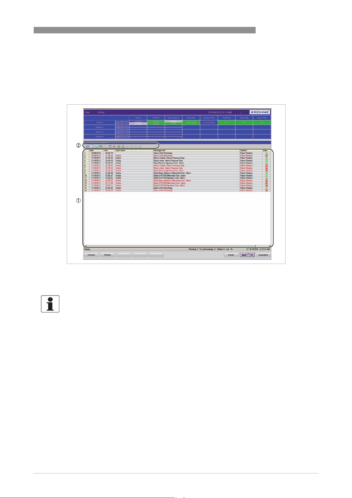
The "Alarm History" screen is showing all pending and historical alarms of the system (e.g. leak
alarms, system alarms).
OPERATION 3
Figure 3-8: Example of "Alarm History" screen
1 List of alarms
2 Control boxes to view and print events of the alarm history list
INFORMATION!
Each message in the "Alarm History" will be displayed in a separate line.
The following information will be shown:
• Number
• Date
• Time
• User name (name of the logged user)
• Message
• Pipeline (running LDS which raised the alarm)
• State of the message (green: coming; red: going)
The controls of the alarm history are offering the same functionality as the ones on the events
Events
screen. For details refer to
The complete list of possible messages can be found on page 41.
on page 26.
www.krohne.com02/2013 - 4002275001 - MA PipePatrol R01 en
29
Page 30
3 OPERATION
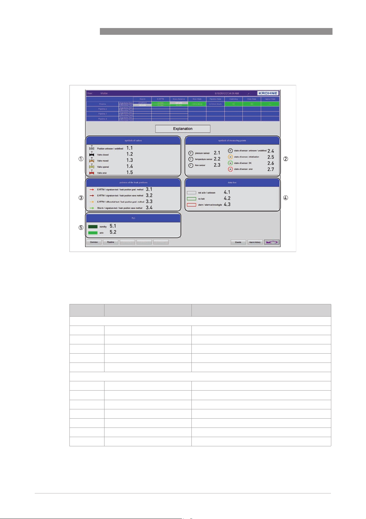
3.4.4 Explanation (Legend)
PIPEPATROL
Figure 3-9: Example of "Legend" screen
1 Symbols of valves
2 Symbols of measuring points
3 Pointers of the leak positions
4 Data box
5 PLC
Symbol Colour of filling/outline Description
Symbols of valves
Symbols of valves 1111
Symbols of valves Symbols of valves
1.1 grey Position unknown / undefined
1.2 black Valve closed
1.3 white/orange Valve moved
1.4 yellow Valve opened
1.5 red Valve error
Symbols of measuring points
Symbols of measuring points 2222
Symbols of measuring points Symbols of measuring points
2.1 black Pressure sensor
2.2 black Temperature sensor
2.3 black Flow sensor
2.4 black State of sensor: unknown / undefined
2.5 orange State of sensor: initialisation
2.6 green State of sensor: OK
2.7 red State of sensor: error
30
www.krohne.com 02/2013 - 4002275001 - MA PipePatrol R01 en
Page 31
PIPEPATROL
Symbol Colour of filling/outline Description
Pointers of the leak positions
Pointers of the leak positions 3333
Pointers of the leak positions Pointers of the leak positions
3.1 red E-RTTM / signature-test / leak position grad. method
3.2 violett E-RTTM / signature-test / leak position wave method
3.3 orange E-RTTM / differential-test / leak position grad. method
3.4 green E-RTTM / differential-test / leak position wave method
Data box
Data box 4444
Data box Data box
4.1 grey not active / unknown
4.2 green no leak
4.3 red alarm / alarm acknowledge
PLC
PLC 5555
PLC PLC
5.1 dark green standby
5.2 green active
3.5 Leak alarm handling
OPERATION 3
In this chapter it is described step by step how a leak alarm should be confirmed and how the
LDS system can be reset.
INFORMATION!
This chapter only concerns the LDS. With regards to possible additional actions, the company
policy should be followed.
In the standard configuration the system differs of four different kinds of leak alarms, which are
coming from four different modules. Three alarms are possible during pumping conditions of
the fluid, Signature-Alarm and Differential-Alarm and Mass Balance-alarm. During Shut-In
operation these modules are disabled. In cases of leak during shut-in conditions, the Shut-In
module will alarm if a leak is recognised.
The following example gives a detailed view on the alarm raises by the Signature-Test module of
the E-RTTM leak detection.
In some cases during transient operation several modules, e.g. Signature-Test and DifferentialTest, are able to raise an alarm. In this case all incoming alarms and leak information will be
displayed. Additionally the alarm will be indicated by an acoustic signal of the Operator Station.
The procedures and the order how to manage a leak alarm coming from another module are
similar to the procedures described in the following. All screens and buttons described in this
chapter are available in the same mode, see the special boxes for each module.
INFORMATION!
Each of the occurred alarms has to be acknowledged separately by the operator.
www.krohne.com02/2013 - 4002275001 - MA PipePatrol R01 en
31
Page 32
3 OPERATION
Alarm handling procedure
Alarm handling procedure
Alarm handling procedureAlarm handling procedure
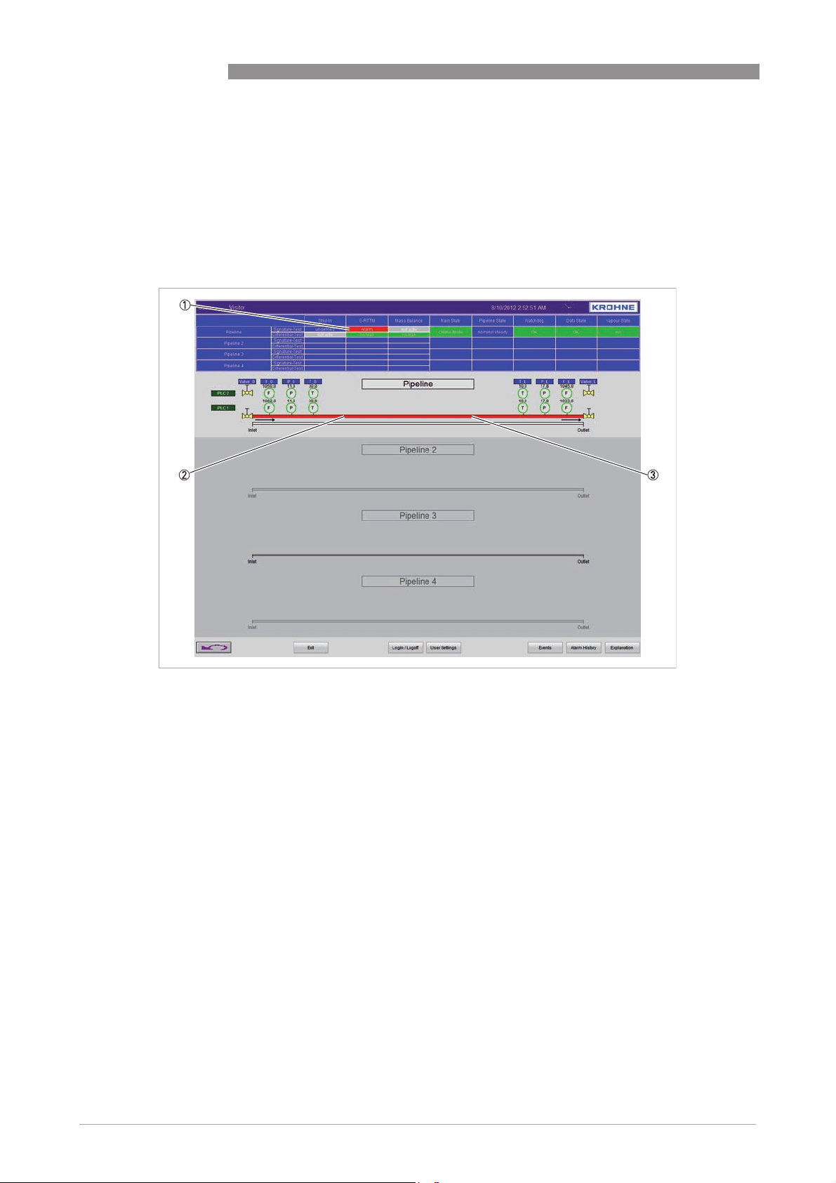
When a leak alarm occurs, this will be highlighted in both the "Status Window" and the "Operator
Window" by means of red boxes (1).
If a leak alarm was raised, by any running LDS, the PipePatrol HMI returns automatically to the
"Main Overview" screen.
Step 1: Recognise leak and switch to "Leak Information" screen
PIPEPATROL
Figure 3-10: Example of leak indication in "Main Window"
1 Module which raise the alarm will be indicate in red (flashing)
2 Alarming system (affected pipeline) will be shown in red
3 Right click on the alarming system to switch to the "Leak Information" screen for details on the leak
32
www.krohne.com 02/2013 - 4002275001 - MA PipePatrol R01 en
Page 33
PIPEPATROL
OPERATION 3
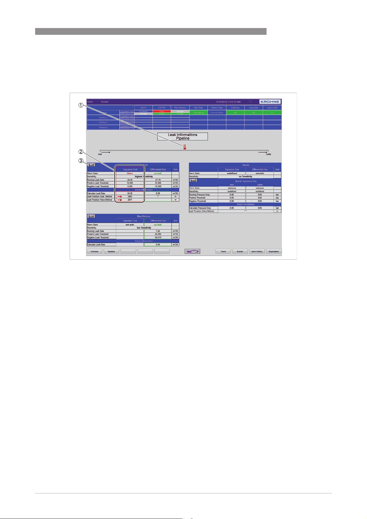
Once the operator selects the alarming system the screen with additional information about the
leak will be shown. In the red box details are given on the leak rate and the leak location.
Step 2: Open leak detection details in "Pipeline Overview" screen
Figure 3-11: Leak detection details in "Pipeline Overview" screen
1 Leak location is showed with an arrow (different colours dep. on the module) along the line
2 Numeric presentation of leak data for the alarming module is shown
3 Control to open the trending of the leak data of the alarming module
www.krohne.com02/2013 - 4002275001 - MA PipePatrol R01 en
33
Page 34
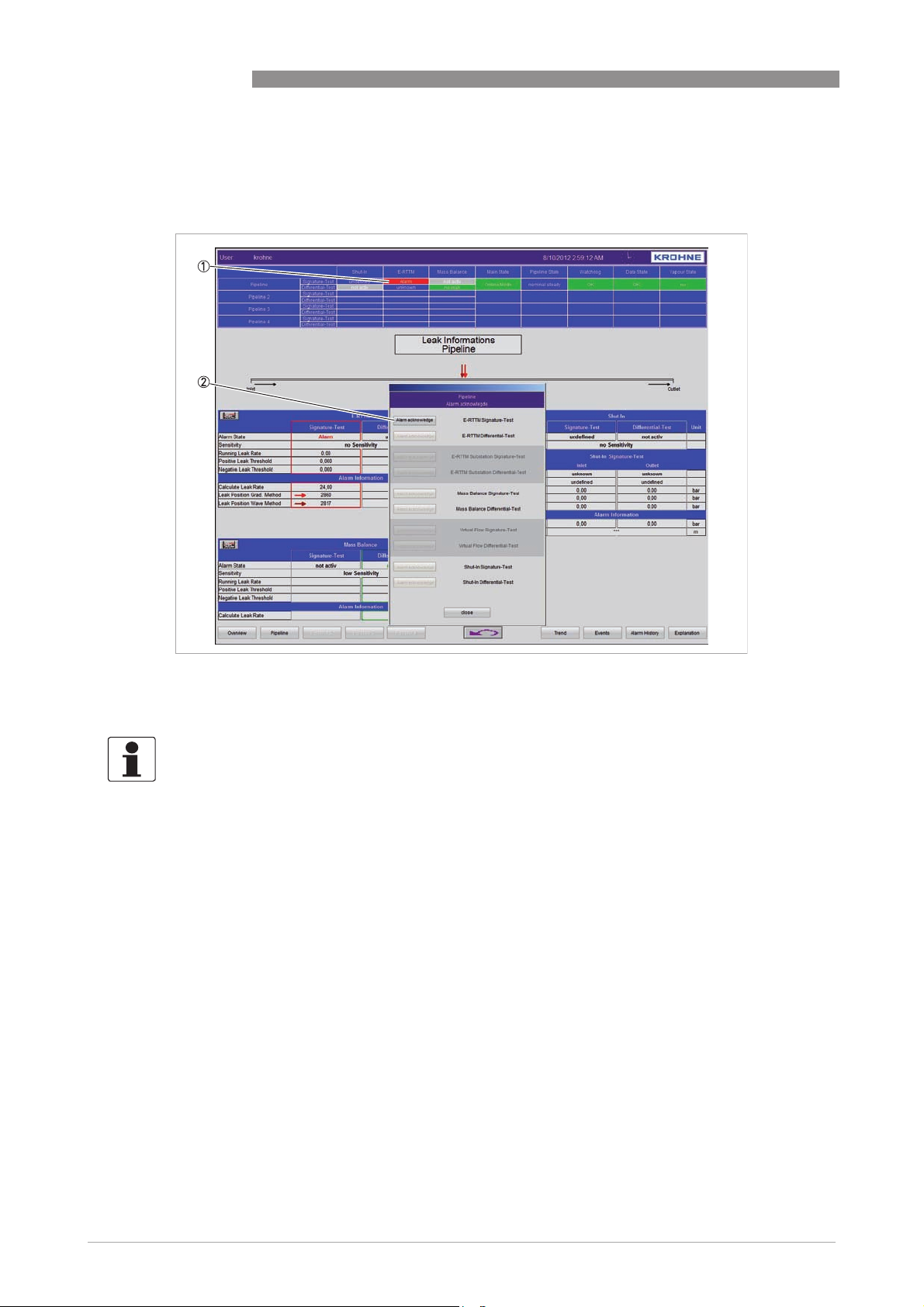
3 OPERATION
Clicking on the alarming box (1) of the module which raised the alarm, opens a dialogue box
with the functionality to acknowledge the alarm (2) and to close afterwards the dialogue box.
Step 3: Acknowledge the alarm
PIPEPATROL
Figure 3-12: Acknowledge the alarm
1 Alarming box to open dialogue for acknowledgement
2 Control to select "Alarm acknowledge"
INFORMATION!
After step 3 it is a good possibility to analyse the leak alarm using the trends and LDS data.
34
www.krohne.com 02/2013 - 4002275001 - MA PipePatrol R01 en
Page 35
PIPEPATROL
OPERATION 3
After the leak alarm has been acknowledged, the operator can either reset the classificatory
only or reset the whole software and reinitialise the LDS.
Reset the classificatory
Reset the classificatory means that the system is running in alarming state and therefore the
Reset the classificatoryReset the classificatory
modules which raised the alarm will not be able to recognise a new leak.
By executing an LDS reset
of the LDS will take more time till the system is ready to detect leaks. This depends for example
on the length of the pipeline, on the numbers of intermediate station along the pipeline, etc.
In these kind of applications it is more practicable if a leak occurs only to reset the classificator
instead of restart the LDS. However, before doing so it must be sure that no leak is present in the
line.
INFORMATION!
To reset any incoming alarm an operator has to be logged into the HMI with the authorisation of
the operator group.
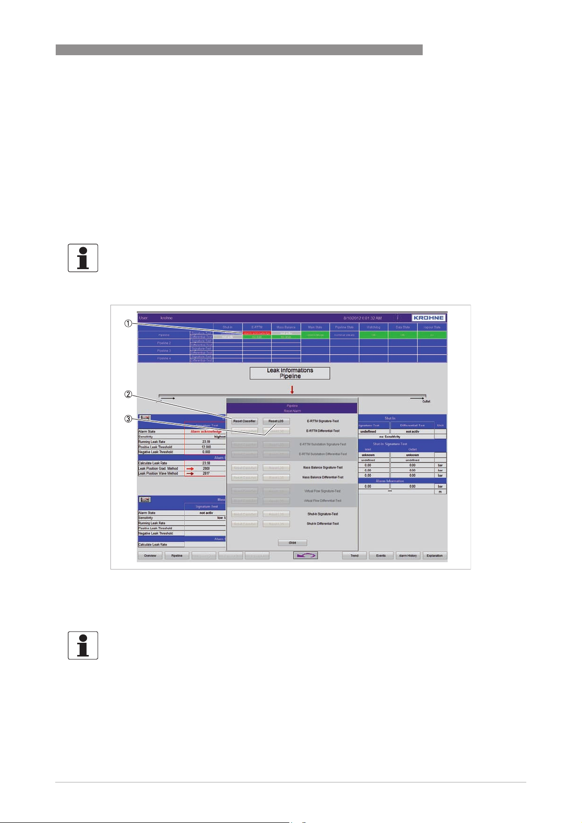
Step 4: Reset the alarm
LDS reset, the system will start again to perform a leak detection. Indeed a reset
LDS resetLDS reset
Figure 3-13: Reset the alarm
1 Alarming box to open dialogue for alarm reset
2 Control to reset the classificator
3 Control to reset the complete leak detection system
INFORMATION!
After a reset of the system, the system will first go into a reinitialising phase. During this phase
no leak information will be available. The time period of this phase is application dependant.
www.krohne.com02/2013 - 4002275001 - MA PipePatrol R01 en
35
Page 36
3 OPERATION
3.6 LDS system commands
3.6.1 Stop and start the LDS
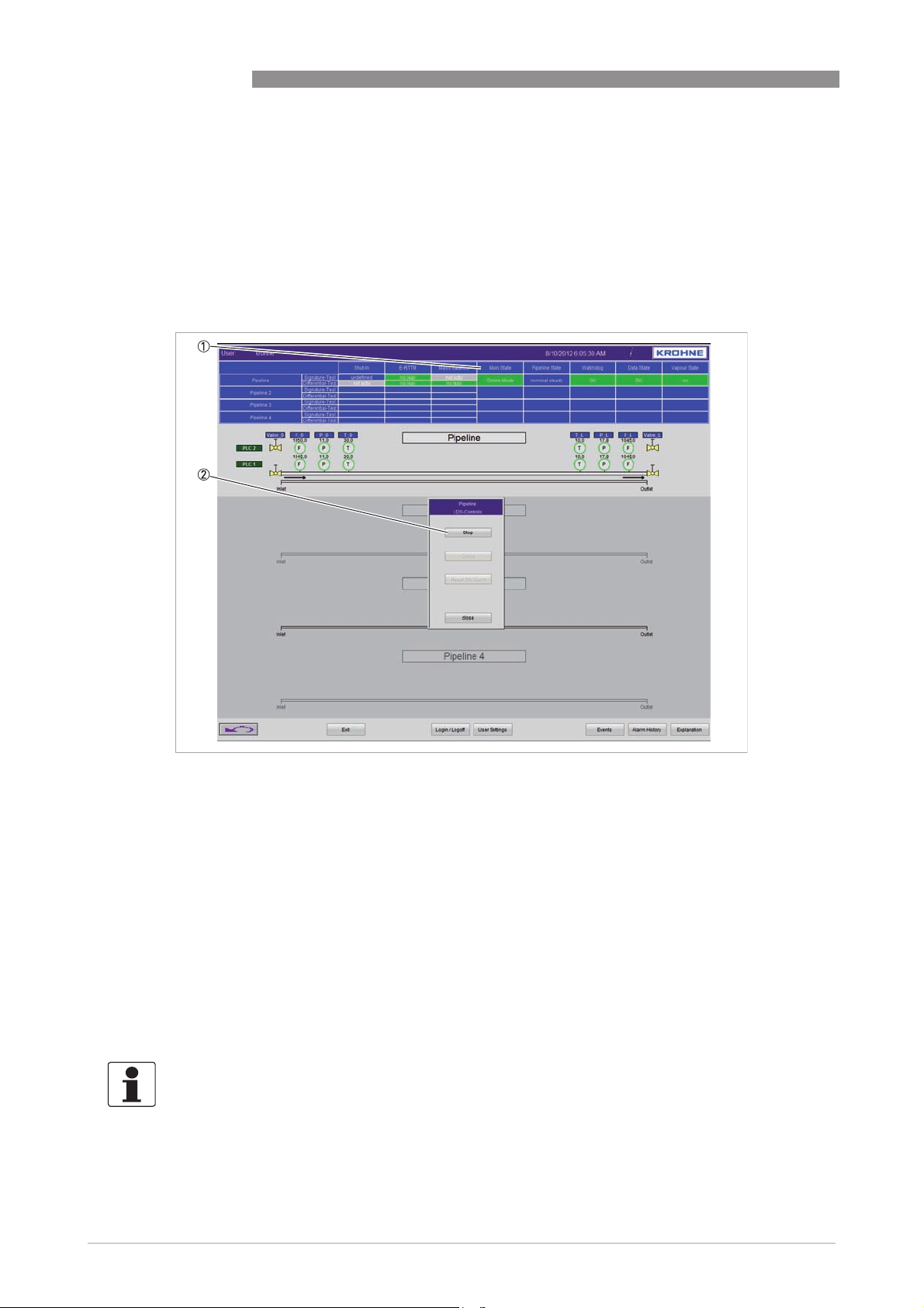
It may be required from time to time to stop the LDS and then to put it back online again. This can
be done from each screen by clicking on "Main State" in the "Status Window" of the selected
system.
PIPEPATROL
Figure 3-14: LDS commands
1 "Main State" box to control the system
2 Select "Stop" to stop the system and afterwards "close" the dialogue box
Only the currently possible commands will be enabled (i.e. if the system is online therefore only
"Stop" is enabled).
• Stop
Stop
StopStop
Stops the LDS for the current pipeline.
• Online
Online
OnlineOnline
Starts the LDS for the current pipeline.
• Reset SW-Alarm
Reset SW-Alarm
Reset SW-AlarmReset SW-Alarm
Resets an application alarm that has been raised for a pipeline (for details refer to
Application alarm
on page 37).
INFORMATION!
Each of the displayed pipelines can be stopped separately.
36
www.krohne.com 02/2013 - 4002275001 - MA PipePatrol R01 en
Page 37
PIPEPATROL
3.6.2 Application alarm
CAUTION!
Weather this malfunction occures, contact the manufacturer immediately to check-up the
system!
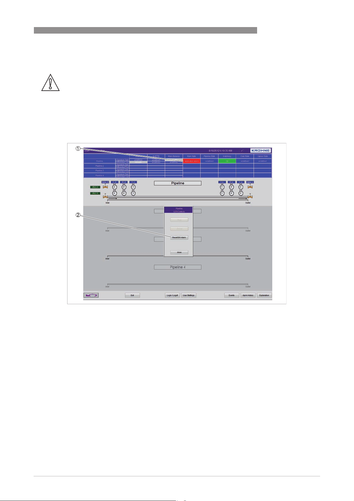
In some cases it could happen that the current system conditions lead into a system failure. If
this happens, the leak detection will stop and raise an application alarm shown in the "Main
State" box of the "Status Window".
OPERATION 3
Figure 3-15: Application alarm and reset of this alarm
1 "Main State" box with the application alarm
2 Select "Reset SW-Alarm" to reset the system and afterwards "close" the dialogue box
After pressing the button (2), the system performs a restart and goes into the "Stop" mode. The
operator has to set the system back online (for details refer to
Stop and start the LDS
on page
36).
www.krohne.com02/2013 - 4002275001 - MA PipePatrol R01 en
37
Page 38

3 OPERATION
3.7 Messages and error handling
In the next pages the alarm messages are rated by a priority. The following table gives you a
description of the priority and the needed action to be taken after appearance of the massage.
Priority Type Action
1 fatal Contact manufacturer.
2 serious Proceed according to the written procedures of your company.
3 low -
4 information only -
3.7.1 List of event messages
Message Priority Description
PIPEPATROL
Leak Alarm State: No
Alarm
Leak Alarm State: Alarm 2 For this pipeline a leak has been detected. One of the alarming module
Leak Alarm State: Alarm
Acknowledge
E-RTTM Signature-Test:
No Leak
E-RTTM Signature-Test:
Alarm
E-RTTM Signature-Test:
Alarm Acknowledge
Shut-In: No Leak 4 The LDS judges this line to be leak free.
Shut-In: Alarm 2 For this pipeline a leak has been detected. A dynamic leak signature during
Shut-In: Alarm
Acknowledge
E-RTTM Differential-Test:
No Leak
E-RTTM Differential-Test:
Alarm
E-RTTM Differential-Test:
Alarm Acknowledge
Mass Balance: No Leak 4 The LDS judges this line to be leak free. No statistic leak signature
Mass Balance: Alarm 2 For this pipeline a leak has been detected. The operator is asked to confirm
Mass Balance: Alarm
Acknowledge
E-RTTM Signature-Test:
Alarm Acknowledge
(User)
E-RTTM Signature-Test:
Reset Classificator (User)
4 The LDS judges this line to be leak free. No one of the alarming module
recognised a leak.
recognised a leak. The operator is asked to confirm the leak.
3 An alarm has been confirmed by the operator.
4 The LDS judges this line to be leak free. No dynamic leak signature
recognised.
2 For this pipeline a leak has been detected. A dynamic leak signature during
pumping conditions has been recognised. The operator is asked to confirm
the leak.
3 An alarm has been confirmed by the operator.
Shut-In conditions has been recognised. The operator is asked to confirm
the leak.
3 An alarm has been confirmed by the operator.
4 The LDS judges this line to be leak free. No slow leak signature recognised.
2 For this pipeline a leak has been detected. A slow leak signature during
pumping conditions has been recognised. The operator is asked to confirm
the leak.
3 An alarm has been confirmed by the operator.
recognised.
the leak. A statistic leak signature during pumping conditions has been
recognised.
3 An alarm has been confirmed by the operator.
3 An alarm has been confirmed by the operator logged on the operator station.
3 A reset of the classificator has been executed by the operator on the
operator station.
38
www.krohne.com 02/2013 - 4002275001 - MA PipePatrol R01 en
Page 39

PIPEPATROL
Message Priority Description
OPERATION 3
E-RTTM Signature-Test:
Reset Leak Detection
(User)
E-RTTM Differential-Test:
Alarm Acknowledge
(User)
E-RTTM Differential-Test:
Reset Classificator (User)
E-RTTM Differential-Test:
Reset Leak Detection
(User)
Mass Balance: Alarm
Acknowledge (User)
Mass Balance: Reset
Classificator (User)
Mass Balance: Reset Leak
Detection (User)
Shut-In: Alarm
Acknowledge (User)
Shut-In: Reset
Classificator (User)
Shut-In: Reset Leak
Detection (User)
Leak Detection E-RTTM:
Initialising
Leak Detection E-RTTM:
Standby
Leak Detection E-RTTM:
Running
Leak Detection E-RTTM:
Error
Leak Detection Shut-In:
Initialising
Leak Detection Shut-In:
Standby
Leak Detection Shut-In:
Running
Leak Detection Shut-In:
Error
Leak Detection Mass
Balance: Initialising
Leak Detection Mass
Balance: Standby
Leak Detection Mass
Balance: Running
Leak Detection Mass
Balance: Error
Data Processing: Best
Condition
Data Processing: Warning 3 One or more signals are not available. The LDS is still running and
Data Processing: Error 1 One or more signals are not available. The LDS is on pending till the
3 A reset of the leak detection has been executed by the operator on the
operator station.
3 An alarm has been confirmed by the operator logged on the operator station.
3 A reset of the classificator has been executed by the operator on the
operator station.
3 A reset of the leak detection has been executed by the operator on the
operator station.
3 An alarm has been confirmed by the operator logged on the operator station.
3 A reset of the classificator has been executed by the operator on the
operator station.
3 A reset of the leak detection has been executed by the operator on the
operator station.
3 An alarm has been confirmed by the operator logged on the operator station.
3 A reset of the classificator has been executed by the operator on the
operator station.
3 A reset of the leak detection has been executed by the operator on the
operator station.
4 The module for model based LD in pumping conditions is starting up and will
be online soon.
4 The module for model based LD in pumping conditions is initialising the
pipeline conditions, after initialisation the module will start-up.
4 The module for model based LD in pumping conditions is running.
1 A serious error occurred automatically (e.g. instrument outtake).
4 The module for leak detection in shut-in conditions is starting up and will be
online soon.
4 The module for leak detection in shut-in conditions is initialising the pipeline
conditions, after initialisation the module will start up.
4 The module for leak detection in shut-in conditions is running.
1 A serious error occurred automatically (e.g. instrument outtake).
4 The statistical leak detection module is starting up and will be online soon.
4 The statistical leak detection module initialising the pipeline conditions,
after initialisation the module will start-up.
4 The statistical leak detection module is running to detect leaks during
standstill conditions.
1 A serious error occurred automatically (e.g. instrument outtake).
4 All field signals are available.
performing leak detection.
necessary measurements are back online.
www.krohne.com02/2013 - 4002275001 - MA PipePatrol R01 en
39
Page 40

3 OPERATION
Message Priority Description
PIPEPATROL
Leak Detection System:
Stop
4 The system has stopped and the following functions are no longer
supported:
• Leak Detection
• Batch tracking (optional)
• Pipeline conditions are recognised
• Data logging
• Nominal value calculation
Leak Detection System:
Online-Mode
4 The system is running and the following functions are supported:
• Leak Detection
• Batch tracking (optional)
• Pipeline conditions are recognised
• Data logging
• Nominal value calculation
Leak Detection System:
Self Test-Mode
Leak Detection System:
Tuning-Mode
Leak Detection System:
Error
Stop Command Leak
Detection System
Online Command Leak
Detection System
Offline Command Leak
Detection System
Reset Command Leak
Detection System
Leak Detection System:
Application Alarm
Flow-Tracker: Unknown 4 The system is starting-up, the classification of the flow is not available.
Flow-Tracker: Standstill
Safe
Flow-Tracker: Standstill 4 The pipeline has been shut down but is still not closed.
Flow-Tracker: Starting up 4 The pumps are starting up.
Flow-Tracker: Shutdown 4 The pumps are shutting down.
Flow-Tracker: Nominal
Unknown
Flow-Tracker: Nominal
High / Low Transient
Flow-Tracker: Nominal
Steady
Pressure-Tracker:
Unknown
Pressure-Tracker: Steady 4 The pipeline is operating in stationary pumping or standstill conditions.
Pressure-Tracker: Low /
High Transient
no connect to LDS-MS 1 The communication between the operator (OS) and monitoring station (MS)
4 The LDS system is being tested using historical data. Leak detection is not
active.
4 Maintenance activities are carried out on the monitoring station. Leak
detection is not active.
1 The application is not running correctly.
3 A stop command has been received. The system is going to shut down.
3 An online command has been received. The system is starting up.
3 An offline command has been received. The system is going to "Self-Test"
mode.
3 A reset has been executed. The system will be restarting.
1 An internal error of the leak detection software has been detected. System
will go in "Stop" mode and can be reset by the user. Please contact our
support.
4 The stand still model is running to detect leaks in a closed pipeline.
4 The pipeline is operating in unknown conditions.
4 The pipeline is operating in transient pumping conditions.
4 The pipeline is operating in stationary pumping conditions.
4 The system is starting-up, the classification of the pressure is not available.
4 The pipeline is operating in transient pumping or standstill conditions.
is connected (e.g. the network connection is lost or the MS is down).
40
www.krohne.com 02/2013 - 4002275001 - MA PipePatrol R01 en
Page 41
PIPEPATROL
3.7.2 List of alarm messages
Message Priority Description
OPERATION 3
State E-RTTM SignatureTest: Alarm
State E-RTTM
Differential-Test: Alarm
State Mass Balance
Differential-Test: Alarm
State Shut-In SignatureTest: Alarm
Shut-In Inlet: Alarm
Pressure Rising
Shut-In Inlet: Alarm
Pressure Drop
Shut-In Outlet: Alarm
Pressure Rising
Shut-In Outlet: Alarm
Pressure Drop
Leak Detection System:
Application Alarm
Alarm LDS-Watchdog 2 A failure of the leak detection system. The Leak Detection software is not
2 The E-RTTM module Signature-Test detects a leak.
2 The E-RTTM module Differential-Test detects a leak.
2 The Mass Balance module Differential-Test detects a leak.
2 The Shut-In module Signature-Test detects a leak.
2 The Shut-In module Signature-Test detects a leak and indicates that the
inlet transmitter shows a positive pressure wave.
2 The Shut-In module Signature-Test detects a leak and indicates that the
inlet transmitter shows a negative pressure wave.
2 The Shut-In module Signature-Test detects a leak and indicates that the
outlet transmitter shows a positive pressure wave.
2 The Shut-In module Signature-Test detects a leak and indicates that the
outlet transmitter shows a negative pressure wave.
2 The system stopped working due to an internal error.
working correctly.
www.krohne.com02/2013 - 4002275001 - MA PipePatrol R01 en
41
Page 42
3 OPERATION
3.7.3 Troubleshooting
For troubleshooting it is necessary that the maintenance crew has a profound knowledge of the
leak detection system.
Possible errors can be divided in internal and external. Internal errors are declared as occurring
in the leak detection software program, e.g. an incorrect parameter setting. External errors are
failures outside the LDS operator or monitoring station, e.g. a failure in the data communication
system.
Internal error
Error Cause Action
PIPEPATROL
The status window of the OS
indicates a system error
No reaction when PC is switched onNo power available Check electrical connection.
The PC does not boot Disk or CD in drive Take out disk and press any key.
PC starts-up, software loads but
LDS is not operational
PC does not boot and internal
speaker gives signal
The data states on the user HMI
reports periodically data errors
The "Status Window" of the user
HMI indicates ERROR OPCConnection
Wrong parameter setting Correct parameter.
Internal error Contact manufacturer.
Power supply failure Check the power supply of each
Other reason Contact manufacturer.
Other reason Contact manufacturer.
Error in software/hardware or
outside the PipePatrol software.
Component in PC broken Contact manufacturer.
Runtime problems caused by the
installed operating system
Connection to the LDS OPCServer fails
LDS station.
Contact manufacturer.
Restart the monitoring station.
If the system is reporting the
error again contact the
manufacturer.
Restart the monitoring station.
If the system is reporting the
error again contact the
manufacturer.
External error
Error Cause Action
42
The "Status Window" of the OS
indicates that the LDS is not
working or "Data State" indicates
data error/warning while the
pipeline is in normal use
A measurement sensor is broken Check status of datacom
Data communication is lost
Some transmitted signals are out
of the predefined range
No signal received from valve
position change
No signal received from batch
change
www.krohne.com 02/2013 - 4002275001 - MA PipePatrol R01 en
Page 43
PIPEPATROL
3.8 Expert functions on Operator Station
3.8.1 User settings
Clicking on the button "User Settings" in the "Main Overview" screen of the PipePatrol HMI,
opens the "User Administration".
In "User Administration" the following settings are available:
• add new users and user group
• change the user permission
• change the access protection
• block specific functions
• automatically log of a user after a certain period
3.8.2 Default passwords
Operating system
The following password allows you to login to both machines: Operator Station and Monitoring
Station
OPERATION 3
Name Password Group
Administrator Administrator Administrator
HMI
The system is delivered with a list of predefined users. That allows the operator crew to login
into the system.
Name Password Group Permissions
Administrator Administrator Administrator All
Visitor Visitor User Change screens
Auto logged after reboot
Operator Operator Operator Change screens
Alarm handling (acknowledge)
Engineer Engineer Engineer Change screens
Process controlling (start/stop LDS)
Alarm handling (acknowledge and
restart)
INFORMATION!
If the current operator doesn't take any actions for more than 10 minutes, his account will be
automatically locked.
www.krohne.com02/2013 - 4002275001 - MA PipePatrol R01 en
43
Page 44

4 SERVICE
4.1 Maintenance on the hardware
Frequently maintenance on the hardware will improve the lifetime and avoid downtime of the
leak detection system. The following maintenance recommendations should be carried out on a
regular basis.
Maintenance on the software is not required.
4.1.1 Filters
The components inside the computer machine are air cooled by a ventilator. Pending on the
pollution of the environment the air filters need to be cleaned regularly. Refer to the manual of
the PC supplier for further details.
4.1.2 Mechanical damages
Regularly check the cables and connectors for damages. In case of a damage replace
immediately the components!
4.2 Availability of services
PIPEPATROL
The manufacturer offers a range of services to support the customer after expiration of the
warranty. These include repair, maintenance, technical support and training.
INFORMATION!
For more precise information, please contact your local sales office.
44
www.krohne.com 02/2013 - 4002275001 - MA PipePatrol R01 en
Page 45

PIPEPATROL
NOTES 5
www.krohne.com02/2013 - 4002275001 - MA PipePatrol R01 en
45
Page 46

5 NOTES
PIPEPATROL
46
www.krohne.com 02/2013 - 4002275001 - MA PipePatrol R01 en
Page 47

PIPEPATROL
NOTES 5
www.krohne.com02/2013 - 4002275001 - MA PipePatrol R01 en
47
Page 48

KROHNE product overview
• Electromagnetic flowmeters
• Variable area flowmeters
• Ultrasonic flowmeters
• Mass flowmeters
• Vortex flowmeters
• Flow controllers
• Level meters
• Temperature meters
• Pressure meters
• Analysis products
• Products and systems for the oil & gas industry
• Measuring systems for the marine industry
Head Office KROHNE Messtechnik GmbH
Ludwig-Krohne-Str. 5
47058 Duisburg (Germany)
Tel.:+49 (0)203 301 0
Fax:+49 (0)203 301 10389
[email protected]
© KROHNE 02/2013 - 4002275001 - MA PipePatrol R01 en - Subject to change without notice.
The current list of all KROHNE contacts and addresses can be found at:
www.krohne.com
 Loading...