

Page 1
Supplementary instructions
Supplementary instructions
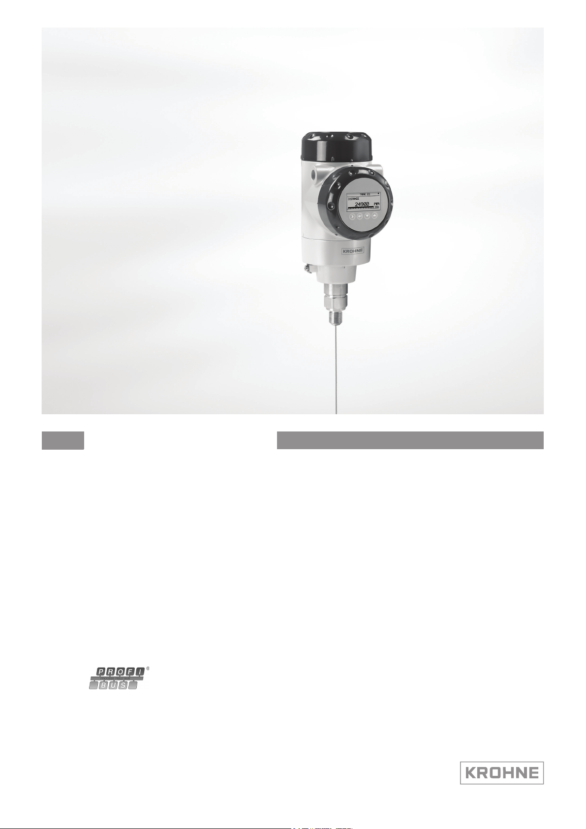
OPTIFLEX 2200 C
OPTIFLEX 2200 C
OPTIFLEX 2200 COPTIFLEX 2200 C
Supplementary instructions Supplementary instructions
2-wire / Guided Radar (TDR) Level Meter
Description of PROFIBUS PA interface
Description of PROFIBUS PA interface
Description of PROFIBUS PA interfaceDescription of PROFIBUS PA interface
The documentation is only complete when it is used in combination with the relevant
documentation of the level meter.
© KROHNE 10/2013 - 4003066801 - MA OPTIFLEX2200C-PA-R01-en-AD
Page 2

CONTENTS
OPTIFLEX 2200 C
1 Safety instructions 3
1.1 Installation........................................................................................................................ 3
1.2 Scope of the document..................................................................................................... 3
1.3 Scope of delivery............................................................................................................... 3
2 PROFIBUS PA 4
2.1 Software history ............................................................................................................... 4
2.2 Device description ............................................................................................................ 4
2.3 Function blocks and the PROFIBUS PA Profile ............................................................... 4
2.4 Technical data................................................................................................................... 5
3 Electrical connection 6
3.1 Topology of a PROFIBUS PA network .............................................................................. 6
3.2 Electrical connection for signal converter....................................................................... 7
4 Commissioning / Operation 8
4.1 Hardware settings ............................................................................................................ 8
4.2 GSD files ......................................................................................................................... 10
4.3 Ident. Number ................................................................................................................ 10
4.4 Configuration of cyclic data transfer.............................................................................. 11
4.5 Cyclic data....................................................................................................................... 12
4.5.1 Input data .............................................................................................................................. 12
4.6 Diagnosis ........................................................................................................................ 17
5 Notes 21
2
www.krohne.com 10/2013 - 4003066801 - MA OPTIFLEX2200C-PA-R01-en-AD
Page 3

OPTIFLEX 2200 C
1.1 Installation
Install the GSD files in your system. If it is necessary to use the process control system to change
the settings of the device, install the DD files. If it is necessary to use PACTware™ to change the
settings of the device, install PACTware™ and the DTM PROFIBUS PA files.
The software, files and installation instructions are given on the DVD-ROM supplied with the
device. You can download the latest version of PACTware™ and the DTM PROFIBUS PA from our
website. For more data, refer to the “readme.txt” files.
1.2 Scope of the document
These instructions are supplementary to the standard product documentation of the signal
converter. The details described herein, in particular the safety information, are valid and shall
be adhered to. The present supplementary instructions provide additional information for the
device when it is connected to a PROFIBUS network.
INFORMATION!
The information in this document only contains the data applicable to the PROFIBUS module.
The technical data in the signal converter Handbook is valid in its current version, provided that it
is not rendered invalid or replaced by these supplementary instructions.
SAFETY INSTRUCTIONS 1
1.3 Scope of delivery
A device for PROFIBUS communication is supplied with:
Supplementary instructions for the PROFIBUS PA interface (this document)
www.krohne.com10/2013 - 4003066801 - MA OPTIFLEX2200C-PA-R01-en-
3
Page 4

2 PROFIBUS PA
2.1 Software history
Issued Signal converter Application program System integration
OPTIFLEX 2200 C
Mth./
Hardware Firmware Hardware Software Driver Version Model name
year
08/13 PROFIBUS PA
module Ident.
No
0x4550
(4001858601c)
V2.42.0.42 Simatic
2.2 Device description
This device is a 2-wire level transmitter that uses TDR (Time Domain Reflectometry) / Guided
Radar technology. It measures the distance of liquids, liquid gases, pastes, powders, slurries
and granular products.
The level transmitter has an MBP (Manchester-coded, bus-powered) interface to connect the
device to a PROFIBUS PA network, when equipped with the appropriate options.
The level transmitter is approved for use in potentially explosive atmospheres when equipped
with the appropriate options.
PCS7
or
other SPS of
other
manufact.
Laptop / PC PDM
HW Config
or
other
Software of
other SPS
manufact.
(≥ 6.0 SP5)DD(Ident.-No.)
Pactware DTM ≥ 1.0.0
GSD (device
specific)
GSD (profile
specific)
KR014550.GSD OPTIFLEX 2200
PA1397.GSD AI 1 (Phy MBP)
2.3 Function blocks and the PROFIBUS PA Profile
The Analog Input Function Block agrees with PROFIBUS PA Profile 3.02. The Analog Input
Function Block is the data interface to a process control system (a PLC, ...). The control system
(cyclic communication services) can read or write input and output data.
INFORMATION!
The PROFIBUS PA Profile 3.02 has a standard set of parameters and functions available for
PROFIBUS devices used in process control. The PROFIBUS device is a function block application
in which parameters and functions are grouped into different blocks.
The device has these blocks:
Block Usage
1 Physical Block (PB) contains identification and diagnosis parameters of the device
1 Level Transducer Block (TB-Level) contains parameters and functions to control the level
4 Analog Input Function Blocks (AI-FB) contains parameters and functions to control the measuring
measurement
output; provides the measuring value(s)
4
www.krohne.com 10/2013 - 4003066801 - MA OPTIFLEX2200C-PA-R01-en-
Page 5

OPTIFLEX 2200 C
The device has 4 slots. The Analog Input Function Blocks use slot 1 (as a virtual module). The
user cannot change this setting. But the user can change the measurement name and unit for
each Function Block. Refer to the table that follows:
INFORMATION!
If it is necessary to change the measurement name, change the channel parameter in the acyclic
PROFIBUS services.
PROFIBUS PA 2
Slot Module
type
1 AI-FB Level (default setting) mm 1
1 Default measurement unit
The calibration units are used as default units.
2.4 Technical data
Hardware
Type PROFIBUS MBP interface. This interface agrees with IEC 61158-2 (bit rate
Device power supply 9...32 V - bus powered; no additional power supply required
Polarity sensitivity No
Base current 14 mA
FDE Yes. The Fault Disconnection Electronics (FDE) operates independently.
Max. error current 20.5 mA
Start current after 10 ms Lower than base current
Measurement name Unit
Distance mm 1
Conversion L 1
Conversion Distance L 1
31.25 kbit/s);
voltage mode (MBP = Manchester-Coded, Bus-Powered)
Software
Supported GSD KR014550.GSD
PA139700.GSD
Device profile PROFIBUS PA Profile V3.02; conformance class B, compact
Address setting Default: 126
Hardware DIP switch: 0…125
PROFIBUS service Set_Slave_Add: 0...125
Factory_Reset=2712: 126
Write protection Password and/or hardware switch
SAPs 2 × MS1 SAPs – acyclic interface to PLC
3 × MS2 SAPs – the number of MS2 Service Access Points is usually equal to
the maximum number of master class 2 tools
Function blocks 1 Physical Block
1 Level Transducer Block
4 Analog Input Function Blocks
www.krohne.com10/2013 - 4003066801 - MA OPTIFLEX2200C-PA-R01-en-
5
Page 6

3 ELECTRICAL CONNECTION
3.1 Topology of a PROFIBUS PA network
The following diagram shows a typical network configuration with PROFIBUS PA devices in
hazardous and non-hazardous areas, as well as the connection of conventional non-PROFIBUS
devices (e.g. with 4 … 20 mA signals) to a PROFIBUS network.
The PROFIBUS PA segment is connected to a segment coupler which, among other things,
provides the conversion to the PROFIBUS DP bus line. In addition it provides the power supply for
bus–powered PROFIBUS PA devices. Refer to the instruction manual of the segment coupler
concerning the DP bus parameters, e.g. the supported baud rates.
OPTIFLEX 2200 C
Figure 3-1: PROFIBUS PA network
1 Control system (PLC); class 1 master
2 Engineering or operation control tool; class 2 master
3 PROFIBUS DP network with max. 12 Mbit/s
4 PROFIBUS PA segment coupler DP / PA
5 PROFIBUS PA network with 31.25 kbit/s
6 HART
7 More devices with 4…20 mA
8 Analogue I/O module
®
device
Refer also to the PROFIBUS PA User and Installation Guideline (Version 2.2, February 2003 PNO
Order No. 2.092).
6
www.krohne.com 10/2013 - 4003066801 - MA OPTIFLEX2200C-PA-R01-en-
Page 7
OPTIFLEX 2200 C
ELECTRICAL CONNECTION 3
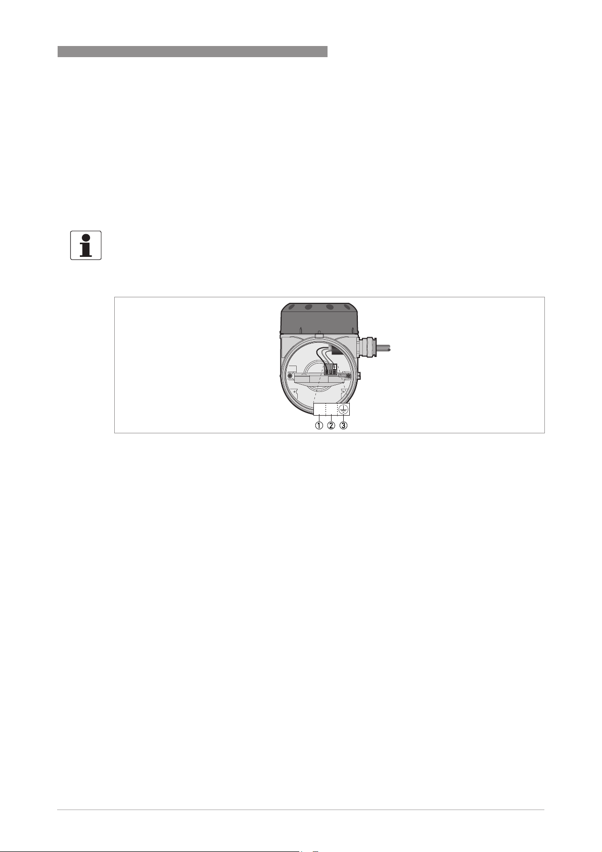
3.2 Electrical connection for signal converter
Bus cable - Shielding and grounding
The statements of the FISCO model only apply if the used bus cable meets the required
specifications.
In order to ensure optimum electromagnetic compatibility of systems it is important that the
system components, and in particular the bus cables, are shielded. These shields must have as
few gaps as possible.
INFORMATION!
The PROFIBUS PA interface of the signal converter will operate only if the power supply is
connected/available. The device terminal is not sensitive to electrical polarity.
Figure 3-2: Electrical installation: terminals
1 Power supply / communication terminal
2 Power supply / communication terminal
3 Grounding terminal
Use the shortest possible length of shield wire to connect the electrical cable to the functional
earth (FE) terminal.
www.krohne.com10/2013 - 4003066801 - MA OPTIFLEX2200C-PA-R01-en-
7
Page 8
4 COMMISSIONING / OPERATION
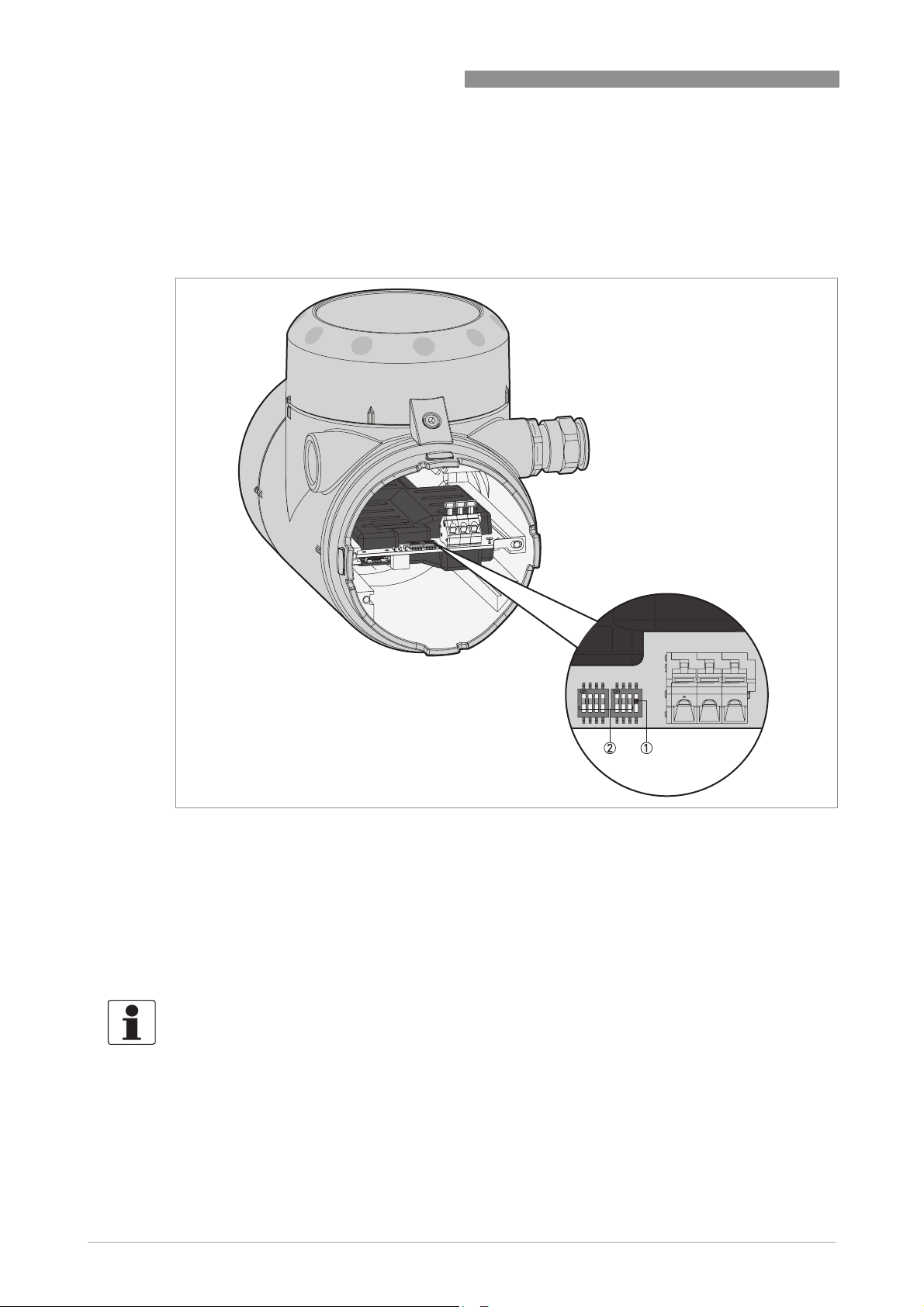
4.1 Hardware settings
There is a DIP switch block with 8 switches on the level transmitter module to set the PROFIBUS
device address and prevent changes to the station address from the network.
OPTIFLEX 2200 C
Figure 4-1: How to use the DIP switches to change the station address
1 Hardware DIP switch
OFF: The user can set the station address with the network bus
ON: The user can set the address of the device with the 7 other DIP swtiches (item 2). You cannot use the network bus
or the local display to change the station address.
2 7 "Station Address" DIP switches. Each DIP switch is a bit position (bits 0...6). Bit 0 is on the left side of the switch
block.The base 10 value of each bit is given in the table that follows. This data is used to calculate the "Station Address"
number.
OFF: binary number "0".
ON: binary number "1".
INFORMATION!
If the Hardware DIP switch is set to "ON", the hardware is locked and you cannot use the network
bus to change the station address.
8
www.krohne.com 10/2013 - 4003066801 - MA OPTIFLEX2200C-PA-R01-en-
Page 9

OPTIFLEX 2200 C
Station address: DIP switch positions
Function Bit DIP switch positions
Hardware 1 7 OFF ON
Station address 6 + 0 + 64
1 If this DIP switch is set to "ON", you cannot use the network bus to change the station address
The station address is calculated by adding the "ON" values of each switch on the DIP switch
block. The default setting for each switch is “OFF”.
COMMISSIONING / OPERATION 4
Value ("OFF") Value ("ON")
5 + 0 + 32
4 + 0 + 16
3 + 0 + 8
2 + 0 + 4
1 + 0 + 2
0 + 0 + 1
Station address
• If the "Station Address" DIP switches are set to a correct station address (≤125), the device
uses this address. The Set_Slave_Add service is not used. Automatic Ident. Number
adaptation is not possible via Set_Slave_Add service in this case. Physical block parameter
FACTORY_RESET code 2712 (reset station address to its default value) is rejected.
• If the "Station Address" DIP switches are set to an incorrect address (>125), the device
ignores this setting. The Set_Slave_Add service and the Physical block parameter
FACTORY_RESET code 2712 (reset station address to its default value) are used. If
No_add_Cfg flag is set to "ON", the device will continue to use FACTORY_RESET code 2712.
• If the "Station Address" DIP switches are changed from an incorrect address to a correct
address, the device uses the address set on the DIP switch block.
• If the "Station Address" DIP switches are changed from a correct address to an incorrect
address, the device will use the default address 126. The flag No_Add_Chg will be set back to
"OFF".
INFORMATION!
You can also use the local display (menu item 2.6.1 ADDRESS) to set the Station Address to a
new value. You can change the value when the Hardware DIP switch is "OFF". If the Hardware
DIP switch is "ON", you can see the Station Address on the local display screen but you cannot
change the value.
www.krohne.com10/2013 - 4003066801 - MA OPTIFLEX2200C-PA-R01-en-
9
Page 10

4 COMMISSIONING / OPERATION
4.2 GSD files
The GSD file contains information that will be needed for configuration of the PROFIBUS DP
communication network. Supplementary files (e.g. ___.bmp and ___.dib) contain icons which will
represent the PROFIBUS devices in the view of the bus configuration system/master system. The
files must be loaded into the configuration program before you connect the device to the
network. Follow the instructions in the manual of the host supplier when installing GSD file and
supplementary files.
The GSD files of all KROHNE devices with PROFIBUS PA interface are available at the KROHNE
internet site for download.
INFORMATION!
If it is supported by the host configuration tool the device entry for the level meter will be located
within the slave family
“
PROFIBUS PA”.
4.3 Ident. Number
Manufacturer specific Ident. Number (4550hex)
Manufacturer specific Ident. Number (4550hex)
Manufacturer specific Ident. Number (4550hex)Manufacturer specific Ident. Number (4550hex)
This setting gives a complete set of operations that can be run on the device. All Functions
Blocks (4 AI-FB) are used for cyclic data transfer. Device-specific diagnosis data is transferred in
addition to the Profile diagnosis.
OPTIFLEX 2200 C
Cyclic layout:
Slot Function Block Valid GSD Modules
1 AI-FB Empty Module
It is necessary to use GSD file KR014550.GSD in this mode. It is possible to use this file for all
types of PROFIBUS DP/PA segment couplers.
AI: Out
INFORMATION!
If a different GSD file is used in the PROFIBUS master system, it is not possibe to transfer cyclic
data.
10
www.krohne.com 10/2013 - 4003066801 - MA OPTIFLEX2200C-PA-R01-en-
Page 11

OPTIFLEX 2200 C
Profile specific Ident. Number (9700hex)
Profile specific Ident. Number (9700hex)
Profile specific Ident. Number (9700hex)Profile specific Ident. Number (9700hex)
The 4 AI-FB are available only for cyclic data transfer. Cyclic PROFIBUS services cannot supply
device-specific diagnosis data. This operational condition can make devices from different
suppliers operate better together. The system will only use functions that are available to all
PROFIBUS PA level transmitters. It is not necessary to change the settings of the control system
to transfer data.
Cyclic layout:
Slot Function Block Valid GSD Modules
COMMISSIONING / OPERATION 4
1 AI-FB Analog Input (AI) short
It is necessary to use GSD file PA139700.GSD in this mode. This file is supplied by PROFIBUS
International (refer to www.profibus.com). It is possible to use this file for all types of PROFIBUS
DP/PA segment couplers. If this file is used, “Condensed Status” is not available.
INFORMATION!
If a different GSD file is used in the PROFIBUS master system, it is not possibe to transfer cyclic
data.
4.4 Configuration of cyclic data transfer
During network configuration the user has to select which function block input/output data shall
be transferred between the PROFIBUS master and the PROFIBUS slave. The GSD file described
above contains several types of modules for this purpose. During configuration a module has to
be assigned to each slot of the device in order to select which data has to be transferred for the
corresponding function blocks. The cyclic layout (see section Ident. Number selector) shows
which module types are valid for each slot. The order of transmission of the data always remains
the same. If an “Empty Module” is assigned to a slot no data will be sent for the corresponding
function block and all function block data following this empty module will move up one position.
Analog Input (AI) long
www.krohne.com10/2013 - 4003066801 - MA OPTIFLEX2200C-PA-R01-en-
11
Page 12

4 COMMISSIONING / OPERATION
4.5 Cyclic data
In a PROFIBUS network cyclic data is described from the point of view of the master. Therefore
input data is transferred from the slave to the master while output data is transferred from the
master to the slave.
4.5.1 Input data
Input data is transferred from the level transmitter to the master for the measuring value. If
input data transfer is configured, 5 bytes are transferred for the corresponding slot:
• 4 byte float value (Float Format according to IEEE Standard 754 Short Real Number)
• 1 byte status value
Float value
Float value
Float valueFloat value
The example that follows shows the format of the float value according to IEEE Standard 754
Short Real Number:
OPTIFLEX 2200 C
Float format
Byte n Byte n+1
Bit7 Bit6 Bit7 Bit6
7
6
5
4
3
2
1
0
VZ
2
2
2
2
2
2
2
2
Exponent Mantissa
Byte n+2 Byte n+3
Bit7 Bit7
-82-92-102-112-122-132-142-152-162-172-182-192-202-212-222-23
2
Mantissa Mantissa
Example (binary): 40 F0 00 00 (hex) = 0100 0000 1111 0000 0000 0000 0000 0000
Formula:
Formula:
Formula:Formula:
VZ
(Exponent – 127)
value = (-1)
value = (-1)
0
* 2
* 2
(129 – 127)
* (1 + Mantissa)
* (1 + 2-1 + 2-2 + 2-3)
value = 1 * 4 * (1 + 0.5 + 0.25 + 0.125)
value = 7.5
-12-22-32-42-52-62-7
2
12
www.krohne.com 10/2013 - 4003066801 - MA OPTIFLEX2200C-PA-R01-en-
Page 13

OPTIFLEX 2200 C
Status value
Status value
Status valueStatus value
The PROFIBUS interface of the level transmitter supports the PROFIBUS-PA Profile Version
3.02. In this Profile the Condensed Status and Diagnosis has replaced by default the Classic
Status and Diagnosis of the PROFIBUS-PA Profile Version 3.0. The Condensed Status and
Diagnosis has been created to make diagnostic events more obvious and to allow predictive and
preventive maintenance. Nevertheless Classic Status and Diagnosis is still available for the level
transmitter. It is implemented for backwards compatibility to "older" devices or PLC systems
which do not support Condensed Status and Diagnosis.
The device may be switched between "Condensed Status and Diagnosis" and "Classic Status and
Diagnosis"
• automatically during start-up of the cyclic data transfer by setting the parameter PRM_COND
within the Set_Prm service data.
• using an engineering tool (e.g. DD/DTM) to write the parameter COND_STATUS_DIAG (slot 0,
index 43).
Coding for both parameters is:
• 0: Classic Status
• 1: Condensed Status (factory setting)
COMMISSIONING / OPERATION 4
INFORMATION!
The parameter COND_STATUS_DIAG cannot be modified directly if cyclic data transfer is active.
Nevertheless it is reset to the factory setting if a reset to default data is requested by an
engineering tool.
The coding of the status value depends on the active status and diagnosis mode. It is described in
the following tables.
Condensed Status
Condensed Status
Condensed StatusCondensed Status
The Condensed Status codes have been defined to allow easier decoding of the information
provided by the PROFIBUS devices. The coding is shown in the following table:
Quality Quality substatus Limits
Gr Gr QS QS QS QS Qu Qu
7
2
0 0 = bad
0 1 = uncertain
1 0 = good (Non Cascade)
1 1 = good (Cascade) - not supported
262
5
4
2
232
2
1
0
2
2
www.krohne.com10/2013 - 4003066801 - MA OPTIFLEX2200C-PA-R01-en-
13
Page 14

4 COMMISSIONING / OPERATION
Status = bad
Quality Quality substatus Limits
Gr Gr QS QS QS QS Qu Qu
7
2
0 0 0 0 0 0 0 0 = non-specific (not provided by the device)
0 0 1 0 0 0 1 1 = passivated (diagnostic alerts inhibited)
0 0 1 0 0 1 x x = maintenance alarm, more diagnosis available
0 0 1 0 1 0 x x = process related, no maintenance
0 0 1 1 1 1 x x = function check / local override; value not usable
Status = uncertain
Quality Quality substatus Limits
Gr Gr QS QS QS QS Qu Qu
7
2
0 1 0 0 1 0 x x = substitute set
0 1 0 0 1 1 1 1 = initial value
0 1 1 0 1 0 x x = maintenance demanded
0 1 1 1 0 0 1 1 = simulated value, start
0 1 1 1 0 1 1 1 = simulated value, end
0 1 1 1 1 0 x x = process related, no maintenance
262
262
5
4
2
5
4
2
232
232
2
1
2
2
1
2
OPTIFLEX 2200 C
0
2
0
2
Status = good (Non Cascade)
Quality Quality substatus Limits
Gr Gr QS QS QS QS Qu Qu
7
2
1 0 0 0 0 0 x x = ok
1 0 0 0 0 1 x x = update event
1 0 0 0 1 0 x x = advisory alarm
1 0 0 0 1 1 x x = critical alarm
1 0 1 0 0 0 x x = initiate fail safe (not provided by the level
1 0 1 0 0 1 x x = maintenance required
1 0 1 0 1 0 x x = maintenance demanded
1 0 1 1 1 1 x x = function check
262
5
4
2
232
2
1
0
2
2
transmitter)
14
www.krohne.com 10/2013 - 4003066801 - MA OPTIFLEX2200C-PA-R01-en-
Page 15

OPTIFLEX 2200 C
Status = Limits
Quality Quality substatus Limits
Gr Gr QS QS QS QS Qu Qu
7
2
Check the first two quality bits in order to get the quality information of the measurement value:
• Good (Non Cascade):
Good (Non Cascade): function block output value is ok and can be used without restrictions
Good (Non Cascade):Good (Non Cascade):
• Good (Cascade):
Good (Cascade): will not be supported, because it is not applicable for the device
Good (Cascade):Good (Cascade):
• Uncertain:
Uncertain: function block output value can be used but the accuracy can not be guaranteed
Uncertain:Uncertain:
(function block outputs value has been frozen, A/D converter is saturated or out of range, ...)
• Bad:
Bad: function block output value is bad - do not use it for process control!
Bad:Bad:
262
COMMISSIONING / OPERATION 4
5
4
2
232
2
1
0
2
2
0 0 = ok
0 1 = low limited
1 0 = high limited
1 1 = constant
The "Quality-Substatus" and "Limit" bits will be used for further diagnostics or limit checking.
INFORMATION!
The status should be monitored because a number will be transmitted even if the status of the
measurement value is bad or uncertain. This is the only way to check the quality of the
transmitted measurement values.
Classic Status
Classic Status
Classic StatusClassic Status
The Classic Status is implemented to provide compatibility to systems which are not configured
for Condensed Status. The coding is shown in the following table:
Quality Quality substatus Limits
Gr Gr QS QS QS QS Qu Qu
7
2
0 0 = bad
0 1 = uncertain
1 0 = good (Non Cascade)
1 1 = good (Cascade) - not supported
262
5
4
2
232
2
1
0
2
2
www.krohne.com10/2013 - 4003066801 - MA OPTIFLEX2200C-PA-R01-en-
15
Page 16

4 COMMISSIONING / OPERATION
Status = bad
Quality Quality substatus Limits
Gr Gr QS QS QS QS Qu Qu
7
2
0 0 0 0 0 0 = non-specific
0 0 0 0 0 1 = configuration error
0 0 0 0 1 0 = not connected
0 0 0 0 1 1 = device failure
0 0 0 1 0 0 = sensor failure
0 0 0 1 0 1 = no communication (last usable value)
0 0 0 1 1 0 = no communication (no usable value)
0 0 0 1 1 1 = out of service
Status = uncertain
Quality Quality substatus Limits
262
5
4
2
232
2
1
2
OPTIFLEX 2200 C
0
2
Gr Gr QS QS QS QS Qu Qu
7
2
262
5
4
2
232
2
1
0
2
2
0 1 0 0 0 0 = non-specific
0 1 0 0 0 1 = last usable value
0 1 0 0 1 0 = substitute-set
0 1 0 0 1 1 = initial value
0 1 0 1 0 0 = sensor conversion not accurate
0 1 0 1 0 1 = engineering unit violation (unit not in the valid set)
0 1 0 1 1 0 = sub-normal
0 1 0 1 1 1 = configuration error
0 1 1 0 0 0 = simulated value
Status = good (Non Cascade)
Quality Quality substatus Limits
Gr Gr QS QS QS QS Qu Qu
7
2
1 0 0 0 0 0 = ok
1 0 0 0 0 1 = update event
1 0 0 0 1 0 = active advisory alarm
1 0 0 0 1 1 = active critical alarm
1 0 0 1 0 0 = unacknowledged update event
1 0 0 1 0 1 = unacknowledged advisory alarm
1 0 0 1 1 0 = unacknowledged critical alarm
1 0 1 0 0 0 = initiate fail safe
1 0 1 0 0 1 = maintenance required
262
5
4
2
232
2
1
0
2
2
16
www.krohne.com 10/2013 - 4003066801 - MA OPTIFLEX2200C-PA-R01-en-
Page 17

OPTIFLEX 2200 C
Status = Limits
Quality Quality substatus Limits
Gr Gr QS QS QS QS Qu Qu
7
2
Check the first two quality bits in order to get the quality information of the measurement value:
• Good (Non Cascade):
Good (Non Cascade): function block output value is ok and can be used without restrictions
Good (Non Cascade):Good (Non Cascade):
• Good (Cascade):
Good (Cascade): will not be supported, because it is not applicable for the device
Good (Cascade):Good (Cascade):
• Uncertain:
Uncertain: function block output value can be used but the accuracy can not be guaranteed
Uncertain:Uncertain:
(function block outputs value has been frozen, A/D converter is saturated or out of range, ...)
• Bad:
Bad: function block output value is bad - do not use it for process control!
Bad:Bad:
262
COMMISSIONING / OPERATION 4
5
4
2
232
2
1
0
2
2
0 0 = ok
0 1 = low limited
1 0 = high limited
1 1 = constant
The "Quality-Substatus" and "Limit" bits will be used for further diagnostics or limit checking.
INFORMATION!
The status should be monitored because a number will be transmitted even if the status of the
measurement value is bad or uncertain. This is the only way to check the quality of the
transmitted measurement values.
4.6 Diagnosis
The device does internal self-tests. The results are given as detailed diagnosis data that agrees
with PROFIBUS PA Profile 3.02. You can set device parameters to see the diagnosis data and you
can also use an engineering tool (DD/DTM, ...) to read it. Cyclic services transfer diagnosis data
to the control system (PLC, ...).
Diagnosis is bitwise coded. Thus it is possible to report more than one indication simultaneously.
The GSD file contains a text for each diagnosis bit to show a text message in the control system.
The references are specified in the UNIT_DIAG_BIT(i) entries. They show which bit is set to
indicate a special diagnosis event.
The quantity and content of diagnosis data depends on the device settings. The active Ident.
Number and the selected status and diagnosis mode will have an effect diagnosis propagation.
The tables that follow show the diagnosis events which are reported for different settings. The
bit number is equal to the count in the GSD file. It gives the position in the device-related
diagnostic field of the Slave_Diag service.
Diagnosis to control system in case of
• Manufacturer specific Ident. Number (4550hex)
• Profile specific Ident. Number (9700hex)
www.krohne.com10/2013 - 4003066801 - MA OPTIFLEX2200C-PA-R01-en-
17
Page 18

4 COMMISSIONING / OPERATION
Bit Number
supported
Description
Correction action
OPTIFLEX 2200 C
16 yes Error appears -
17 yes Error disappears -
1
24
Hardware failure electronics Restart the device. If the error occurs again: send the device back
to the manufacturer with an indication of the error.
1
27
Electronic temperature too low Electronic temperature below -40°C. Comply with the application
limits with regard to temperature of the medium and ambient
temperature. If the process conditions are within the specified
limits: send the device back to the manufacturer with an
indication of the error.
Electronic temperature too high Electronic temperature above +85°C. Comply with the application
limits with regard to temperature of the medium and ambient
temperature. If the process conditions are within the specified
limits: send the device back to the manufacturer with an
indication of the error.
1
28
Memory error Reset the device to Factory/Default settings. If the error occurs
again: send the device back to the manufacturer with an
indication of the error.
1
29
Measurement failure Check process conditions (Flow/Level, Temperature). If the
process conditions are within the specified limits: send the device
back to the manufacturer with an indication of the error.
1
34
Configuration invalid Reset the device to Factory/Default settings. If the error occurs
again: send the device back to the manufacturer with an
indication of the error.
35 yes Restart Device is restarted because of power-up or warmstart request. In
case of unexpected restart: send the device back to the
manufacturer with an indication of the error.
36 yes Coldstart Device is reset to its Factory/Default settings because of a user
request or exchange of the basic module (serial number is
changed). Recover user specific parameter settings.
37 yes Maintenance required Linearization or temperature compensation is not operating
correct. See for detailed failure message or send the device back
to the manufacturer with an indication of the error.
39 yes Ident_Number violation Ident. Number Selector was modified while cyclic data transfer
was active. To clear this message perform one of the following
actions:
• Reset Ident. Number Selector to its former setting
• Stop cyclic data transfer
• Restart the device
2
40
42
43
55 yes Extension available Refer to detailed diagnosis in bits 56 to 103.
56
57
Maintenance alarm Check detailed diagnosis. Restart the device. If the error occurs
again: send the device back to the manufacturer with an
indication of the error.
2
Function check Simulation is active. Disable simulation to clear this message.
2
Invalid process condition Check process conditions (Flow/Level, Temperature). If the
process conditions are within the specified limits: send the device
back to the manufacturer with an indication of the error.
3
Converter EEPROM Error Replace the signal converter.For more data, refer to the
handbook.
3
Converter RAM Error Replace the signal converter.For more data, refer to the
handbook.
18
www.krohne.com 10/2013 - 4003066801 - MA OPTIFLEX2200C-PA-R01-en-
Page 19

OPTIFLEX 2200 C
Bit Number
supported
Description
3
58
59
60
61
63
64
65
66
67
68
72
73
75
76
Converter ROM Error Replace the signal converter.For more data, refer to the
3
Sensor EEPROM Error Replace the signal converter.For more data, refer to the
3
Sensor RAM Error Replace the signal converter.For more data, refer to the
3
Sensor ROM Error Replace the signal converter.For more data, refer to the
3
Oscillator Frequency Failure Replace the signal converter.For more data, refer to the
3
Converter Voltage Error Replace the signal converter.For more data, refer to the
3
Sensor Voltage Error Do a check of the power supply at the device terminals. Make sure
3
Internal Communication Error De-energize the device. Make sure that the signal cable engages
3
Temperature Out of Range Error Measure the ambient temperature. De-energize the device until
3
Sensor not compatible Go to menu 1.1.0 IDENT. in Configuration mode. Record the
3
Reference Lost Error Speak to your supplier to make sure that the electronics are still
3
Level Lost Error Measure the level of the contents in the tank using another
3
Overfill Error Remove some of the product until the level is below the blocking
3
No Probe detected Error Replace the signal converter.For more data, refer to the
COMMISSIONING / OPERATION 4
Correction action
handbook.
handbook.
handbook.
handbook.
handbook.
handbook.
that voltage values are in the specified limits in menu item 2.2.2
DIAGNOSTIC (Configuration mode / Supervisor menu). If the
voltage is correct, replace the signal converter. For more data on
how to replace the signal converter, refer to the handbook.
in the terminal and the screw connection is tight. Energize the
device. If the problem continues, replace the signal converter. For
more data, refer to the handbook.
the ambient temperature is back in the given range. If the
temperature does not stay in the correct range, make sure that
there is insulation around the signal converter. If this error
occurs 2 times, replace the device.
version numbers of the device software given in menu items 1.1.2,
1.1.3 and 1.1.4. Give this data to the supplier.
functioning correctly. Make sure that your installation has ESD
protection. For more data, refer to the handbook.
method of measurement. If the tank is empty (the level is below
the end of the probe), then fill the tank until product level is in the
measurement range. If the tank is full (the level is in the blocking
distance), then remove the contents from the tank until the level
is back in the measuring range. If the product was lost and the
tank is neither full nor empty, wait for the device to find the level
again.
If the device has to measure a product with εr≥1.6, refer to MEAS.
AMP. (Measured Pulse Amplitude, menu item 2.5.6) and then
adjust MEAS. THRESH. (measurement threshold, menu item
2.5.7). If the product has a low dielectric constant (εr<1.6) and the
device is in TBF mode, refer to PROBE END AMP (probe end pulse
amplitude, menu item 2.5.8) and then adjust PROBE END TH.
(probe end threshold, menu item 2.5.9). For more data, refer to
the handbook.
Make sure that the signal converter is correctly attached the
probe. For more data, refer to the handbook.
distance.
handbook.
www.krohne.com10/2013 - 4003066801 - MA OPTIFLEX2200C-PA-R01-en-
19
Page 20

4 COMMISSIONING / OPERATION
Bit Number
supported
80
Description
3
Flange Lost Warning Risk of device failure. Replace electronics module or contact the
Correction action
OPTIFLEX 2200 C
supplier.
3
82
Snapshot Invalid Do a check of the device, tank and the process.
Do a new snapshot recording. If necessary, contact the supplier.
3
84
Reference Position Outside Range Risk of device failure. Replace electronics module or contact the
supplier.
3
85
Audio Signal Offset Outside Range Risk of device failure. Replace electronics module or contact the
supplier.
3
86
Temperature Below -35°C Measure the ambient temperature. De-energize the device until
the ambient temperature is back in the given range. If the
temperature does not stay in the correct range, make sure that
there is insulation around the signal converter.
3
87
Temperature Above +75°C Measure the ambient temperature. De-energize the device until
the ambient temperature is back in the given range. If the
temperature does not stay in the correct range, make sure that
there is insulation around the signal converter.
3
90
Temperature out of range warning Measure the ambient temperature. De-energize the device until
the ambient temperature is back in the given range. If the
temperature does not stay in the correct range, make sure that
there is insulation around the signal converter.
3
93
Local Operation The device is in configuration mode. A supervisor has used the
LCD display of the device to enter a menu. Use the LCD display to
go back to normal mode.
3
100
No OF2200C Connection De-energize the device. Make sure that the signal cable engages
in the terminal and the screw connection is tight. Energize the
device. If the problem continues, replace the signal converter. For
more data, refer to the handbook.
1 Indication is supported if Classic Diagnosis is active only.
2 Indication is supported if Condensed Diagnosis is active only.
3 Indication is supported in cyclic diagnosis only if Ident. Number 4550 hex is active. Nevertheless this information is always available via
acyclic access (e.g. by using DD / DTM) for all Ident. Numbers supported.
20
www.krohne.com 10/2013 - 4003066801 - MA OPTIFLEX2200C-PA-R01-en-
Page 21

OPTIFLEX 2200 C
NOTES 5
www.krohne.com10/2013 - 4003066801 - MA OPTIFLEX2200C-PA-R01-en-
21
Page 22

5 NOTES
OPTIFLEX 2200 C
22
www.krohne.com 10/2013 - 4003066801 - MA OPTIFLEX2200C-PA-R01-en-
Page 23

OPTIFLEX 2200 C
NOTES 5
www.krohne.com10/2013 - 4003066801 - MA OPTIFLEX2200C-PA-R01-en-
23
Page 24

KROHNE product overview
• Electromagnetic flowmeters
• Variable area flowmeters
• Ultrasonic flowmeters
• Mass flowmeters
• Vortex flowmeters
• Flow controllers
• Level meters
• Temperature meters
• Pressure meters
• Analysis products
• Products and systems for the oil & gas industry
• Measuring systems for the marine industry
Head Office KROHNE Messtechnik GmbH
Ludwig-Krohne-Str. 5
47058 Duisburg (Germany)
Tel.:+49 (0)203 301 0
Fax:+49 (0)203 301 10389
info@krohne.de
© KROHNE 10/2013 - 4003066801 - MA OPTIFLEX2200C-PA-R01-en-AD - Subject to change without notice.
The current list of all KROHNE contacts and addresses can be found at:
www.krohne.com
 Loading...