

Page 1
Technical Datasheet
Technical Datasheet
OPTIWAVE 1010
OPTIWAVE 1010
OPTIWAVE 1010OPTIWAVE 1010
Technical DatasheetTechnical Datasheet
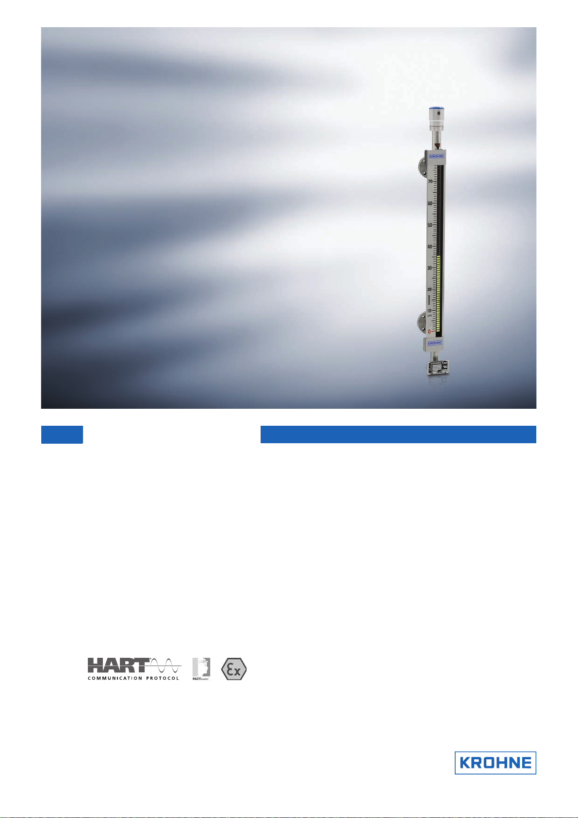
Radar (FMCW) Level Transmitter for bypass chambers
and magnetic level indicators (BM 26 Advanced)
•
Device welded to a bypass chamber with an optional IP68 level indicator (BM 26
Advanced) – for the continuous measurement of clean liquids
•
Device is configured and ready to use before it leaves the factory
•
Measuring distance up to 8 m / 26.2 ft
© KROHNE 10/2016 - 4004263503 - TD OPTIWAVE 1010 R03 en
Page 2

CONTENTS
OPTIWAVE 1010
1 Product features 3
1.1 The FMCW radar level transmitter for bypass chambers ............................................... 3
1.2 Overview............................................................................................................................ 4
1.3 Measuring principle.......................................................................................................... 6
2 Technical data 7
2.1 Technical data................................................................................................................... 7
2.2 Measuring accuracy ....................................................................................................... 11
2.3 Minimum power supply voltage ..................................................................................... 13
2.4 Dimensions and weights ................................................................................................ 14
3 Installation 16
3.1 Pre-installation requirements ....................................................................................... 16
3.2 Pressure and temperature ranges ................................................................................ 16
3.3 Recommended mounting position ................................................................................. 19
3.4 Mounting restrictions ..................................................................................................... 19
4 Electrical connections 20
4.1 Electrical installation: 2-wire, loop-powered ................................................................ 20
4.2 Electrical connection for current output ....................................................................... 20
4.2.1 Non-Ex devices ..................................................................................................................... 20
4.2.2 Devices for hazardous locations........................................................................................... 21
4.3 Networks ........................................................................................................................ 21
4.3.1 General information.............................................................................................................. 21
4.3.2 Point-to-point connection..................................................................................................... 21
4.3.3 Multi-drop networks ............................................................................................................. 22
5 Order information 23
5.1 Order code ...................................................................................................................... 23
5.2 Accessories..................................................................................................................... 25
6 Notes 26
2
www.krohne.com 10/2016 - 4004263503 - TD OPTIWAVE 1010 R03 en
Page 3
OPTIWAVE 1010
PRODUCT FEATURES
1.1 The FMCW radar level transmitter for bypass chambers
The OPTIWAVE 1010 is a non-contact FMCW radar welded to a bypass chamber with an optional
IP68 level indicator (BM 26 Advanced). It continuously measures the distance and level of clean
liquids.
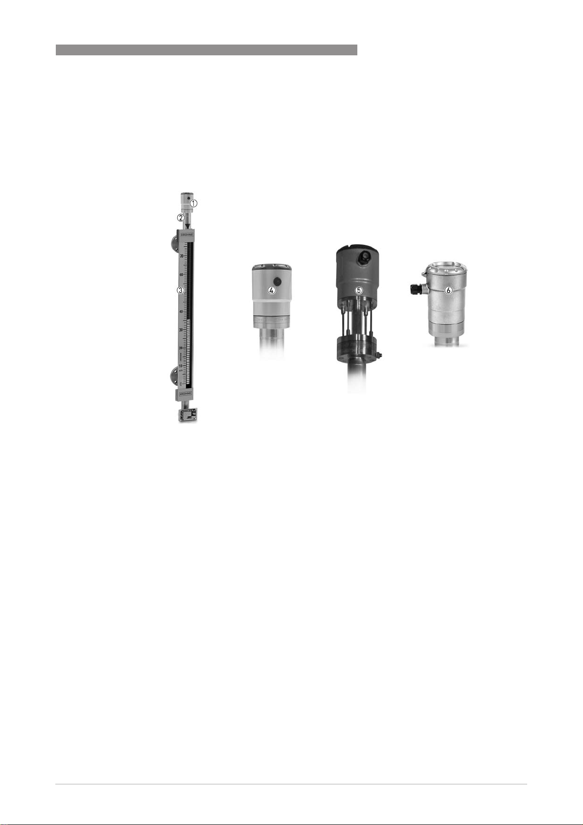
1
1 OPTIWAVE 1010 radar level transmitter
2 Welded connection (matching element)
3 BM 26 Advanced magnetic level indicator (MLI) or bypass chamber
4 Standard aluminium housing
5 Aluminium housing with distance piece
6 Stainless steel housing
Highlights
• 2-wire, loop-powered, HART®, 6 GHz Radar (FMCW) Level Transmitter for clean liquids
• Welded to a bypass chamber or BM 26 Advanced MLI
• Device is configured and ready to use before it leaves the factory
• Adjustments possible using HART® communication / DTM / DDs
• ±5mm/ 0.2¨ accuracy
• Measuring distance up to 8 m / 26.2 ft
• Metaglas® or Metapeek seal (dual process seal system)
• Max. process conditions +150°C / +302°F and 40 barg / 580 psig
• No minimum dielectric constant when using a float
www.krohne.com10/2016 - 4004263503 - TD OPTIWAVE 1010 R03 en
3
Page 4
1
PRODUCT FEATURES
Industries
• Chemical market
• Power
• Water & Wastewater
• Automotive
• HVACR (heating, ventilation, air conditioning and refrigeration)
Applications
• Raw material storage
• Water hammer arresters
• Liquefied gas
• Hydraulic oil
• Cooling water and steam condensates
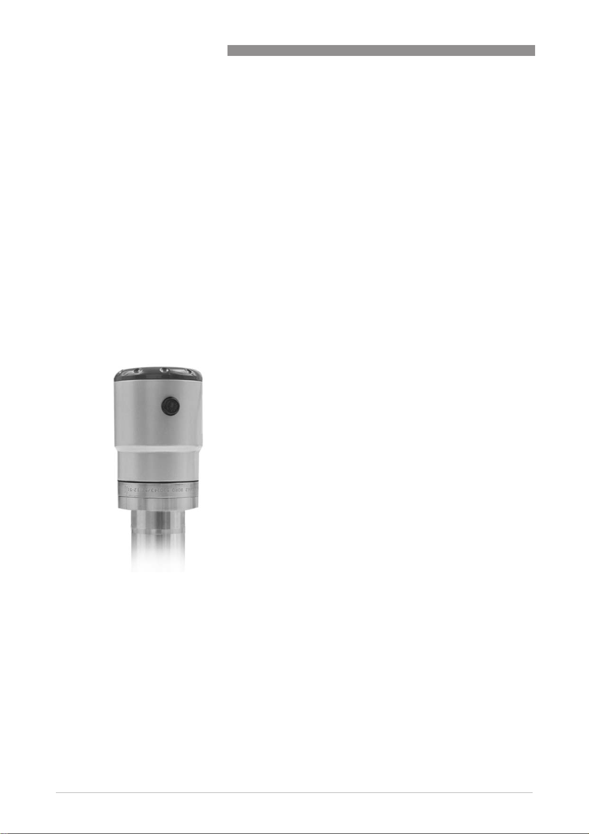
1.2 Overview
Standard aluminium housing
OPTIWAVE 1010
• Max. process connection temperature:
+100°C / +212°F
• Max. process pressure: 16 barg / 232 psig
• Metapeek process seal
4
www.krohne.com 10/2016 - 4004263503 - TD OPTIWAVE 1010 R03 en
Page 5
OPTIWAVE 1010
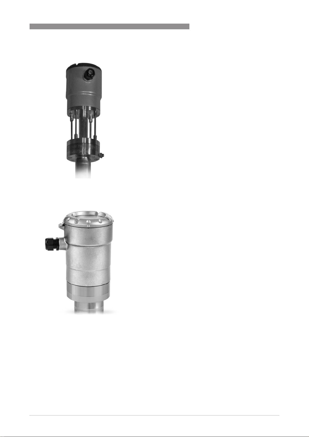
Aluminium housing with distance piece
PRODUCT FEATURES
• Max. process connection temperature:
+150°C / +302°F
• Max. process pressure: 40 barg / 580 psig
• Metaglas® process seal
1
Stainless steel housing
• Max. process connection temperature:
+120°C / +248°F
• Max. process pressure: 40 barg / 580 psig
• Metaglas® process seal
www.krohne.com10/2016 - 4004263503 - TD OPTIWAVE 1010 R03 en
5
Page 6
1
PRODUCT FEATURES
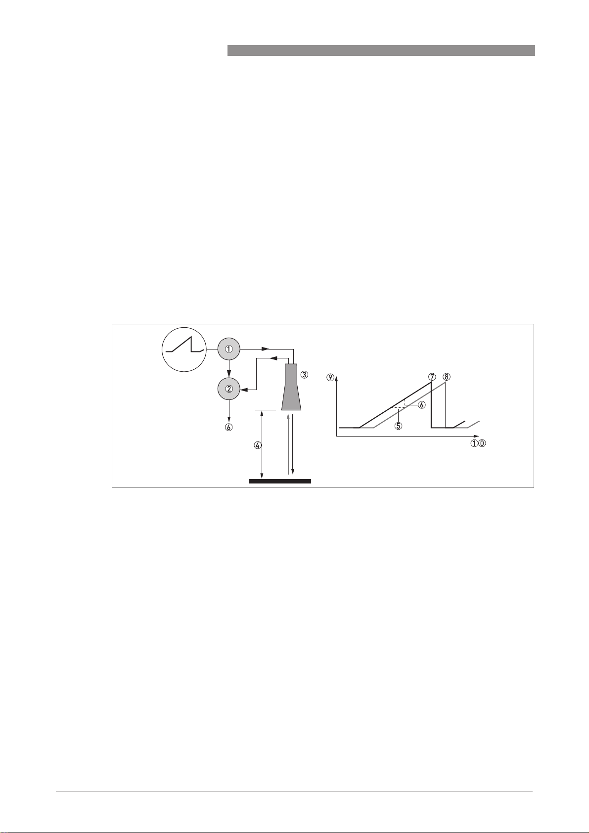
1.3 Measuring principle
A radar signal is emitted via an antenna, reflected from the product surface and received after a
time t. The radar principle used is FMCW (Frequency Modulated Continuous Wave).
The FMCW-radar transmits a high frequency signal whose frequency increases linearly during
the measurement phase (called the frequency sweep). The signal is emitted, reflected on the
measuring surface and received with a time delay, t. Delay time, t=2d/c, where d is the distance
to the product surface and c is the speed of light in the gas above the product.
For further signal processing the difference Δf is calculated from the actual transmitted
frequency and the received frequency. The difference is directly proportional to the distance. A
large frequency difference corresponds to a large distance and vice versa. The frequency
difference Δf is transformed via a Fourier transformation (FFT) into a frequency spectrum and
then the distance is calculated from the spectrum. The level results from the difference between
the maximum distance and the measured distance.
OPTIWAVE 1010
Figure 1-1: Measuring principle of FMCW radar
1 Transmitter
2 Mixer
3 Antenna
4 Distance to product surface, where change in frequency is proportional to distance
5 Differential time delay, Δt
6 Differential frequency, Δf
7 Frequency transmitted
8 Frequency received
9 Frequency
10 Time
6
www.krohne.com 10/2016 - 4004263503 - TD OPTIWAVE 1010 R03 en
Page 7

OPTIWAVE 1010
TECHNICAL DATA
2.1 Technical data
•
The following data is provided for general applications. If you require data that is more
relevant to your specific application, please contact us or your local sales office.
•
Additional information (certificates, special tools, software,...) and complete product
documentation can be downloaded free of charge from the website (Downloadcenter).
Measuring system
Measuring principle 2-wire loop-powered level transmitter; C-band (6 GHz) FMCW radar
Application range Level indication of liquids in applications up to 40 barg / 580 psig
Primary measured value Distance to the surface of the liquid (or the top of the float, if the liquid has a low
Secondary measured value Level of the liquid in the bypass chamber
Design
Construction The measurement system consists of a bypass chamber, a signal converter and an
Measuring range 0.3...5.6 m / 0.98...18.4 ft (max. 8 m / 26.2 ft)
Top dead zone Minimum value: 300 mm / 11.8¨ from the matching element
User interface
User interface
User interfaceUser interface
User interface PACTware™
dielectric constant)
optional float
2
Measuring accuracy
Repeatability ±2mm/ ±0.08¨
Accuracy Standard: ±10 mm / ±0.4¨ without calibration or with a 2-point calibration
Influence of temperature on the
bypass chamber
Reference conditions acc. to DIN EN 61298-1
Reference conditions acc. to DIN EN 61298-1
Reference conditions acc. to DIN EN 61298-1Reference conditions acc. to DIN EN 61298-1
Temperature +18...+30°C / +64...+86°F
Pressure 860...1060 mbara / 12.5...15.4 psia
Relative air humidity 45...75%
Target A special float with a target is installed in the bypass chamber and used to calibrate
Option: ±5mm/ ±0.2¨ with a 5-point calibration¨
0.01 mm/1 m of distance/°C (relative to +25°C) /
0.000216¨/1 ft of distance/°F (relative to +77°F)
the device
1
Operating conditions
Temperature
Temperature
TemperatureTemperature
Ambient temperature -40…+85°C/ -40…+185°F
Storage temperature -40…+85°C/ -40…+185°F
Ex: see supplementary operating instructions or approval certificates
www.krohne.com10/2016 - 4004263503 - TD OPTIWAVE 1010 R03 en
7
Page 8

2
TECHNICAL DATA
OPTIWAVE 1010
Process temperature Standard aluminium version with Metapeek process seal:
Pressure
Pressure
PressurePressure
Process pressure Standard (with Metapeek):
Other conditions
Other conditions
Other conditionsOther conditions
Minimum dielectric constant (εr) Not applicable. If εr <3, a float with a target is used.
Ingress protection IEC 60529: IP66/67
Maximum rate of change 10 m/min / 32.8 ft/min
Measurement update rate Typically 2 measurement cycles/s
Standard aluminium version with Metapeek process seal:
Standard aluminium version with Metapeek process seal:Standard aluminium version with Metapeek process seal:
with a Kalrez® 6375 gasket: -20...+100°C / -4...+212°F
with a FKM/FPM gasket: -40...+100°C / -40...+212°F
with a EPDM gasket: -40...+100°C / -40...+212°F
Aluminium version with distance piece and Metaglas
Aluminium version with distance piece and Metaglas® process seal:
Aluminium version with distance piece and MetaglasAluminium version with distance piece and Metaglas
with a Kalrez® 6375 gasket: -20...+150°C / -4...+302°F
with a FKM/FPM gasket: -40...+150°C / -40...+302°F
with a EPDM gasket: -40...+150°C / -40...+302°F
Stainless steel version with Metaglas
Stainless steel version with Metaglas® process seal:
Stainless steel version with MetaglasStainless steel version with Metaglas
with a Kalrez® 6375 gasket: -20...+120°C / -4...+248°F
with a FKM/FPM gasket: -40...+120°C / -40...+248°F
with a EPDM gasket: -40...+120°C / -40...+248°F
The process connection temperature must agree with the temperature limits of the
gasket material.
Ex: see supplementary operating instructions or approval certificates
Standard (with Metapeek): -1…16 barg / -14.5…232 psig
Standard (with Metapeek):Standard (with Metapeek):
With Metaglas
With Metaglas®:::: -1…40 barg / -14.5…580 psig
With MetaglasWith Metaglas
process seal:
process seal: process seal:
2
3
3
process seal:
process seal: process seal:
Installation conditions
Dimensions and weights For dimensions and weights data, refer to
the technical data sheet for the BM 26 Basic / Advanced.
Dimensions and weights
on page 14 and
Materials
Housing Standard: Polyester-coated aluminium
Option: Stainless steel (1.4408 / 316)
Wetted materials Standard: Stainless steel (1.4404 / 316L) bypass chamber / magnetic level indicator
Process seal Standard Aluminium: Metapeek process seal with O-ring
Cable gland Standard: none
Weather protection (option) Stainless steel (1.4404 / 316L)
with a PEEK cone in the matching element and a FKM/FPM, EPDM or Kalrez® 6375
O-ring
Aluminium version with distance piece: Metaglas® process seal with O-ring
Stainless steel version: Metaglas® process seal with O-ring
Options: Plastic (Non-Ex: black, Ex ia-approved: blue); nickel-plated brass;
stainless steel
8
www.krohne.com 10/2016 - 4004263503 - TD OPTIWAVE 1010 R03 en
Page 9

OPTIWAVE 1010
TECHNICAL DATA
Process connections
The device is welded to the top of the bypass chamber of the magnetic level indicator. For more data about the process
connections of the magnetic level indicator, refer to the technical data sheet for the BM 26 Basic / Advanced.
Electrical connections
Power supply Non-Ex, Ex db- and Ex tb-approved devices
Maximum current 22 mA
Current output load RL [Ω] ≤ ((U
Cable entry Standard: M20×1.5; Option: ½ NPT
Cable gland Standard: none
Cable entry capacity (terminal) 0.5…2.5 mm²
Non-Ex, Ex db- and Ex tb-approved devices
Non-Ex, Ex db- and Ex tb-approved devicesNon-Ex, Ex db- and Ex tb-approved devices
14.5…32 VDC; min./max. value for an output of 22 mA at the terminals
Ex ia-approved devices
Ex ia-approved devices
Ex ia-approved devicesEx ia-approved devices
14.5…30 VDC; min./max. value for an output of 22 mA at the terminals
-14.5 V)/22 mA). For more data, refer to
voltage
Options: M20×1.5 (cable diameter: 6...10 mm / 0.2...0.39¨); others are available on
request
ext
on page 13.
Minimum power supply
2
Input and output
Current output / HART
Current output / HART®
Current output / HARTCurrent output / HART
Output signal 4…20 mA HART® or 3.8…20.5 mA acc. to NAMUR NE 43
Resolution ±3 µA
Analog temperature drift Typically 50 ppm/K (150 ppm/K maximum)
Digital temperature drift Typically ±5mm/ 0.2¨ – max. 15 mm / 0.59¨ for the full temperature range
Error signal High: 22 mA; Low: 3.6 mA acc. to NAMUR NE 43
4
Approvals and certification
CE The device meets the essential requirements of the EU Directives. The
Vibration resistance EN 60068-2-6 / IEC 61298-3
Explosion protection
Explosion protection
Explosion protectionExplosion protection
ATEX (Ex ia or Ex db or Ex tb)
KIWA 15ATEX0022 X
IECEx (Ex ia or Ex db or Ex tb)
IECEx KIW 15.0012 X
manufacturer certifies successful testing of the product by applying the CE
marking.
For more data about the EU Directives and European Standards related to this
device, refer to the EU Declaration of Conformity. You can find this documentation
on the DVD-ROM supplied with the device or it can be downloaded free of charge
from the website (Download Center).
10-82.2 Hz: 0.15 mm; 82.2-1000 Hz: 20 m/s²
II 1/2 G Ex ia IIC Tx Ga/Gb;
II 2 D Ex ia IIIC T120°C Db (stainless steel housing only);
II 1/2 G Ex db IIC T6...T4 Ga/Gb (stainless steel housing only);
II 2 D Ex tb IIIC T120°C Db (stainless steel housing only)
Ex ia IIC Tx Ga/Gb;
Ex ia IIIC T120°C Db (stainless steel housing only);
Ex db IIC T6...T4 Ga/Gb (stainless steel housing only);
Ex tb IIIC T120°C Db (stainless steel housing only)
5
5
www.krohne.com10/2016 - 4004263503 - TD OPTIWAVE 1010 R03 en
9
Page 10

2
TECHNICAL DATA
Other standards and approvals
Other standards and approvals
Other standards and approvalsOther standards and approvals
EMC Electromagnetic Compatibility (EMC) directive
Radio approvals EU
LVD Essential requirements of Low-Voltage (LVD) directive
NAMUR NAMUR NE 43 Standardization of the Signal Level for the Failure Information of
Construction code Option: NACE MR0175 / ISO 15156; NACE MR0103
1 For more data, refer to the "Measuring accuracy" section in this chapter
2 Kalrez® is a registered trademark of DuPont Performance Elastomers L.L.C. The process connection temperature must agree with
the temperature limits of the gasket material.
3 Metaglas® is a registered trademark of Herberts Industrieglas, GMBH & Co., KG. The process connection temperature must agree
with the temperature limits of the gasket material.
4 HART® is a registered trademark of the HART Communication Foundation
5 Tx = T6...T4 (without a distance piece) or T6...T3 (with a distance piece)
EU
EUEU
Radio Equipment directive
FCC Rules
FCC Rules
FCC RulesFCC Rules
Part 15
Industry Canada
Industry Canada
Industry CanadaIndustry Canada
License-exempt RSS-210
Digital Transmitters
NAMUR NE 53 Software and Hardware of Field Devices and Signal Processing
Devices with Digital Electronics
NAMUR NE 107 Self-Monitoring and Diagnosis of Field Devices
OPTIWAVE 1010
10
www.krohne.com 10/2016 - 4004263503 - TD OPTIWAVE 1010 R03 en
Page 11

OPTIWAVE 1010
2.2 Measuring accuracy
Use these graphs to find the measuring accuracy for a given distance from the transmitter.
Measuring accuracy without calibration or after 2-point calibration (with a 2-point
calibration certificate)
TECHNICAL DATA
2
Figure 2-1: Measuring accuracy / distance from the process connections of the bypass chamber, in mm
X: Distance from the top process connection [mm]
Y: Accuracy [+yy mm / -yy mm]
1: 200 mm
2: Float offset. Refer to the "Basic parameters" menu in the DTM for the float offset value.
Figure 2-2: Measuring accuracy / distance from the process connections of the bypass chamber, in inches
X: Distance from the top process connection [inches]
Y: Accuracy [+yy¨ / -yy¨]
1: 7.9¨
2: Float offset. Refer to the "Basic parameters" menu in the DTM for the float offset value.
www.krohne.com10/2016 - 4004263503 - TD OPTIWAVE 1010 R03 en
11
Page 12

2
TECHNICAL DATA
Measuring accuracy after 5-point calibration (with a 5-point calibration certificate)
Figure 2-3: Measuring accuracy / distance from the process connections of the bypass chamber, in mm
X: Distance from the top process connection [mm]
Y: Accuracy [+yy mm / -yy mm]
1: 200 mm
2: Float offset. Refer to the "Basic parameters" menu in the DTM for the float offset value.
3: 200 mm
OPTIWAVE 1010
12
Figure 2-4: Measuring accuracy / distance from the process connections of the bypass chamber, in inches
X: Distance from the top process connection [inches]
Y: Accuracy [+yy¨ / -yy¨]
1: 7.9¨
2: Float offset. Refer to the "Basic parameters" menu in the DTM for the float offset value.
3: 7.9¨
www.krohne.com 10/2016 - 4004263503 - TD OPTIWAVE 1010 R03 en
Page 13

OPTIWAVE 1010
2.3 Minimum power supply voltage
Use these graphs to find the minimum power supply voltage for a given current output load.
Non-Ex devices or devices with a Hazardous Location approval (Ex db / Ex tb)
TECHNICAL DATA
2
Figure 2-5: Minimum power supply voltage for an output of 22 mA at the terminal (Non-Ex devices or devices with a
Hazardous Location approval (Ex db / Ex tb))
X: Power supply U [VDC]
Y: Current output load R
L
[Ω]
Devices with a Hazardous Location approval (Ex ia)
Figure 2-6: Minimum power supply voltage for an output of 22 mA at the terminal (devices with a Hazardous Location
approval (Ex ia))
X: Power supply U [VDC]
Y: Current output load R
L
[Ω]
www.krohne.com10/2016 - 4004263503 - TD OPTIWAVE 1010 R03 en
13
Page 14

2
TECHNICAL DATA
2.4 Dimensions and weights
Device versions
Figure 2-7: Device versions
1 Non-Ex or Ex ia-approved device (aluminium housing – standard version)
2 Non-Ex or Ex ia-approved device (aluminium housing – with distance piece)
3 Non-Ex, Ex ia- Ex db- or Ex tb-approved device (stainless steel housing)
Device versions: Dimensions in mm and inches
OPTIWAVE 1010
Dimensions Device versions
Aluminium:
non-Ex or Ex ia-approved
(standard)
non-Ex or Ex ia-approved
Aluminium:
(with distance piece)
Stainless steel:
non-Ex, Ex ia, Ex db or
Ex tb-approved
[mm] [inches] [mm] [inches] [mm] [inches]
aaaa 98 3.86 98 3.86 99.5 3.92
bbbb 178 7.01 278 10.94 189 7.44
cccc 138 5.43 138 5.43 133 5.24
dddd 153 6.02 253 9.96 164 6.46
eeee 14 0.55 14 0.55 14 0.55
ffff 42.4 1.67 42.4 1.67 42.4 1.67
gggg 90 3.54 90 3.54 90 3.54
hhhh 64.5 2.54 164 6.47 60 2.36
14
www.krohne.com 10/2016 - 4004263503 - TD OPTIWAVE 1010 R03 en
Page 15

OPTIWAVE 1010
Weather protection
Figure 2-8: Device versions with the weather protection option
1 Non-Ex or Ex ia-approved device (aluminium housing – standard version)
2 Non-Ex or Ex ia-approved device (aluminium housing – with distance piece)
3 Non-Ex, Ex ia- Ex db- or Ex tb-approved device (stainless steel housing)
Devices with weather protection: Dimensions in mm and inches
Dimensions Devices with weather protection
TECHNICAL DATA
2
Aluminium:
non-Ex or Ex ia-approved
(standard)
non-Ex or Ex ia-approved
Aluminium:
(with distance piece)
Stainless steel:
non-Ex, Ex ia, Ex db or
Ex tb-approved
[mm] [inches] [mm] [inches] [mm] [inches]
aaaa 154 6.06 154 6.06 154 6.06
bbbb 119 4.69 119 4.69 98 3.86
cccc 136 5.35 136 5.35 118 4.65
dddd 183 7.20 272 10.71 186 7.32
Weights
Type of device Weights
Aluminium Stainless steel
without weather
protection
[kg] [lb] [kg] [lb] [kg] [lb] [kg] [lb]
Non-Ex / intrinsically-safe (Ex ia)
Non-Ex / intrinsically-safe (Ex ia)
Non-Ex / intrinsically-safe (Ex ia)Non-Ex / intrinsically-safe (Ex ia)
Standard 2.54 5.61 3.87 8.53 — — — —
With distance piece 3.52 7.76 4.85 10.69 — — — —
with weather
protection
without weather
protection
with weather
protection
Non-Ex / intrinsically-safe (Ex ia) / Explosion proof (Ex db) / Protected by enclosure (Ex tb)
Non-Ex / intrinsically-safe (Ex ia) / Explosion proof (Ex db) / Protected by enclosure (Ex tb)
Non-Ex / intrinsically-safe (Ex ia) / Explosion proof (Ex db) / Protected by enclosure (Ex tb)Non-Ex / intrinsically-safe (Ex ia) / Explosion proof (Ex db) / Protected by enclosure (Ex tb)
Standard — — — — 3.85 8.49 5.18 11.42
www.krohne.com10/2016 - 4004263503 - TD OPTIWAVE 1010 R03 en
15
Page 16

3
INSTALLATION
3.1 Pre-installation requirements
Obey the precautions that follow to make sure that the device is correctly installed.
• Make sure that there is sufficient space on all sides.
• Protect the signal converter from direct sunlight.
• Do not subject the signal converter to heavy vibrations.
3.2 Pressure and temperature ranges
OPTIWAVE 1010
If the ambient temperature is more than +70
°
C / +158°F, there is a risk of injury if you touch the
device. Use a protective cover or metallic grid to prevent injury.
Figure 3-1: Pressure and temperature ranges
1 Bypass chamber temperature
Non-Ex devices: Depends on the device versions and the seal material. Refer to the table that follows.
Ex devices: see supplementary operating instructions
2 Ambient temperature
Non-Ex devices: -40...+85°C / -40...+185°F
Ex devices: see supplementary operating instructions
3 Process pressure
Depends on the type of seal and process connection. Refer to the table that follows.
16
www.krohne.com 10/2016 - 4004263503 - TD OPTIWAVE 1010 R03 en
Page 17

OPTIWAVE 1010
Aluminium housing for non-Ex and Ex ia-approved devices
INSTALLATION
3
Version Seal Distance piece Bypass chamber
Process pressure
temperature
[°C] [°F] [barg] [psig]
Metapeek FKM/FPM with
Metapeek
Kalrez® 6375
with Metapeek
EPDM with
Metapeek
Metaglas®
and
distance
piece
FKM/FPM with
Metaglas®
Kalrez® 6375
with Metaglas®
EPDM with
Metaglas®
without -40...+100 -40...+212 -1...16 -14.5...232
without -20...+100 -4...+212
without -40...+100 -40...+212
with -40...+150 -40...+302 -1...40 -14.5...580
with -20...+150 -4...+302
with -40...+150 -40...+302
Stainless steel housing for non-Ex , Ex ia-, Ex db- and Ex tb-approved devices
Version Seal Distance piece Bypass chamber
temperature
[°C] [°F] [barg] [psig]
Metaglas® FKM/FPM with
Metaglas®
Kalrez® 6375
with Metaglas®
EPDM with
Metaglas®
without -40...+120 -40...+248 -1...40 -14.5...580
without -20...+120 -4...+248
without -40...+120 -40...+248
Process pressure
www.krohne.com10/2016 - 4004263503 - TD OPTIWAVE 1010 R03 en
17
Page 18

3
INSTALLATION
Ambient temperature / process temperature, in °C
Figure 3-2: Ambient temperature / process temperature, in °C
OPTIWAVE 1010
Ambient temperature / process temperature, in °F
Figure 3-3: Ambient temperature / process temperature, in °F
1 Maximum ambient temperature, °C
2 Maximum process temperature, °C
3 Maximum ambient temperature, °F
4 Maximum process temperature, °F
5 Device with aluminium housing
6 Device with stainless steel housing
7 Device with aluminium housing and distance piece
18
The maximum ambient temperature for non-Ex devices is +85°C / +185°F. The process
connection temperature must agree with the temperature limits of the gasket material.
www.krohne.com 10/2016 - 4004263503 - TD OPTIWAVE 1010 R03 en
Page 19

OPTIWAVE 1010
3.3 Recommended mounting position
Follow these recommendations to make sure that the device measures correctly. They have an
effect on the performance of the device.
Make sure that the cable glands are aligned with the process connections of the bypass
chamber.
INSTALLATION
3
Figure 3-4: Recommended mounting position
1 Internal tube diameter. Min. ... Max.: 38...56 mm / 1.50...2.20¨
2 Float offset (the distance between the surface of the liquid and the radar target on top of the float).
Min. ... Max.: 0...200 mm / 0...7.87¨.
3 Distance to top process connection (bypass chamber) = minimum distance (refer to the "basic parameters" menu in
the DTM)
4 Distance to bottom process connection (bypass chamber) = maximum distance (refer to the "basic parameters" menu
in the DTM)
3.4 Mounting restrictions
Follow these recommendations to make sure that the device measures correctly. They have an
effect on the performance of the device.
If the device uses a float to measure the level of the liquid, slowly pressurize the bypass
chamber. A float can damage the PEEK cone of the radar level transmitter at the top of the
bypass chamber.
If there are parasitic signals, the device will not measure correctly. Parasitic signals are caused
by sudden changes in bypass chamber diameter in the path of the radar beam.
www.krohne.com10/2016 - 4004263503 - TD OPTIWAVE 1010 R03 en
19
Page 20

4
ELECTRICAL CONNECTIONS
4.1 Electrical installation: 2-wire, loop-powered
Figure 4-1: Terminals for electrical installation
1 Grounding terminal in the housing (if the electrical cable is shielded)
2 Current output terminal – polarity insensitive
3 Current output terminal – polarity insensitive
4 External ground connection
OPTIWAVE 1010
Electrical power to the output terminal energizes the device. The output terminal is also used for
®
HART
communication.
4.2 Electrical connection for current output
4.2.1 Non-Ex devices
Figure 4-2: Electrical connections for non-Ex devices
1 Power supply
2 Resistor for HART® communication
3 Optional connection to the grounding terminal
4 Output: 14.5...32 VDC for an output of 22 mA at the terminal
5 Device
20
Electrical polarity has no effect on device operation.
www.krohne.com 10/2016 - 4004263503 - TD OPTIWAVE 1010 R03 en
Page 21

OPTIWAVE 1010
4.2.2 Devices for hazardous locations
For electrical data for device operation in hazardous locations, refer to the related certificates of
compliance and supplementary instructions (ATEX, IECEx etc.). You can find this documentation
on the DVD-ROM delivered with the device or it can be downloaded free of charge from the
website (Download Center).
4.3 Networks
4.3.1 General information
The device uses the HART® communication protocol. This protocol agrees with the HART®
Communication Foundation standard. The device can be connected point-to-point. It can also
operate in a network with a device address from 1 to 63.
The device output is factory-set to communicate point-to-point. To change the communication
mode from point-to-point
4.3.2 Point-to-point connection
point-to-point to multi-drop
point-to-pointpoint-to-point
multi-drop, refer to "HART" in the handbook.
multi-dropmulti-drop
ELECTRICAL CONNECTIONS
4
Figure 4-3: Point-to-point connection (non-Ex)
1 Address of the device (0 for point-to-point connection)
2 4...20 mA + HART®
3 Resistor for HART® communication
4 Power supply
5 HART® converter
6 HART® communication software
www.krohne.com10/2016 - 4004263503 - TD OPTIWAVE 1010 R03 en
21
Page 22

4
ELECTRICAL CONNECTIONS
4.3.3 Multi-drop networks
OPTIWAVE 1010
Figure 4-4: Multi-drop network (non-Ex)
1 Address of the device (each device must have a different address in multidrop networks)
2 4mA + HART®
3 Resistor for HART® communication
4 Power supply
5 HART® converter
6 HART® communication software
22
www.krohne.com 10/2016 - 4004263503 - TD OPTIWAVE 1010 R03 en
Page 23

OPTIWAVE 1010
5.1 Order code
The measuring system has 2 parts:
• The OPTIWAVE 1010 radar (FMCW) level transmitter. Give the order code – refer to the table
that follows.
• The BM26 Advanced (magnetic level indicator (MLI) or bypass chamber). Give the order code
– refer to the table for the Advanced version (with OPTIWAVE 1010)
Basic/Advanced technical data sheet
Make a selection from each column to get the full order code. The characters of the order code
highlighted in light grey describe the standard.
ORDER INFORMATION
Advanced version (with OPTIWAVE 1010) in the BM26
Advanced version (with OPTIWAVE 1010)Advanced version (with OPTIWAVE 1010)
5
VF01 4 OPTIWAVE 1010 6 GHz Radar (FMCW) Level Transmitter for bypass chambers and magnetic level indicators
VF01
VF01 4 Order code (complete this code on the pages that follow)
VF01VF01
OPTIWAVE 1010 6 GHz Radar (FMCW) Level Transmitter for bypass chambers and magnetic level indicators
OPTIWAVE 1010 6 GHz Radar (FMCW) Level Transmitter for bypass chambers and magnetic level indicators OPTIWAVE 1010 6 GHz Radar (FMCW) Level Transmitter for bypass chambers and magnetic level indicators
(BM 26 ADVANCED)
(BM 26 ADVANCED)
(BM 26 ADVANCED)(BM 26 ADVANCED)
Converter version (Housing material
Converter version (Housing material – protection class)
Converter version (Housing material Converter version (Housing material
1 OPTIWAVE 1010: Compact version (Aluminium – IP66 / IP67)
2 OPTIWAVE 1010: Compact version (Stainless steel – IP66 / IP67)
3 OPTIWAVE 1010: Compact version (Aluminium – IP66/67) with distance piece for electronic spare parts
only
Approval
Approval
ApprovalApproval
0 Without
1 ATEX II 1/2 G Ex ia IIC Tx Ga/Gb + II 2 D Ex ia IIIC T120°C
2 ATEX II 1/2 G Ex db IIC T6…T4 Ga/Gb + II 2 D Ex tb IIIC T120°C Db
6 IECEx Ex ia IIC Tx Ga/Gb + Ex ia IIIC T120°C Db
7 IECEx Ex db IIC T6…T4 Ga/Gb + Ex tb IIIC T120°C Db
1
Other approval
Other approval
Other approvalOther approval
0 Without
B EAC Russia
C EAC Belarus
K EAC Kazakhstan
Order code (complete this code on the pages that follow)
Order code (complete this code on the pages that follow)Order code (complete this code on the pages that follow)
6
6
6
protection class)
protection class) protection class)
4
2
3
5
www.krohne.com10/2016 - 4004263503 - TD OPTIWAVE 1010 R03 en
23
Page 24

5
ORDER INFORMATION
Process seal
Process seal – Temperature / Pressure / Material / Remarks (material to be checked by the
Process seal Process seal
customer)
customer)
customer)customer)
0 Without
1 -40°C...+100°C (-40°F…+212°F) / -1…16 barg (-14.5…232 psig) / FKM/FPM / aluminium
housing and Metapeek process seal
2 -40°C...+100°C (-40°F…+212°F) / -1…16 barg (-14.5…232 psig) / EPDM / aluminium housing
and Metapeek process seal
3 -20°C...+100°C (-4°F…+212°F) / -1…16 barg (-14.5…232 psig) / Kalrez® 6375 / aluminium
housing and Metapeek process seal
5 -40°C...+150°C (-40°F…+302°F) / -1...40 barg (-14.5…580 psig) / FKM/FPM / aluminium
housing, Metaglas® process seal and distance piece
6 -40°C...+150°C (-40°F…+302°F) / -1...40 barg (-14.5…580 psig) / EPDM / aluminium housing,
Metaglas® process seal and distance piece
7 -20°C...+150°C (-4°F…+302°F) / -1...40 barg (-14.5…580 psig) / Kalrez® 6375 / aluminium
housing, Metaglas® process seal and distance piece
A -40°C...+120°C (-40°F…+248°F) / -1...40 barg (-14.5…580 psig) / FKM/FPM / stainless steel
housing and Metaglas® process seal
B -40°C...+120°C (-40°F…+248°F) / -1...40 barg (-14.5…580 psig) / EPDM / stainless steel
housing and Metaglas® process seal
C -20°C...+120°C (-4°F…+248°F) / -1...40 barg (-14.5…580 psig) / Kalrez® 6375 / stainless steel
housing and Metaglas® process seal
Antenna: Matching element / Material
Antenna: Matching element / Material
Antenna: Matching element / MaterialAntenna: Matching element / Material
0 Without
1 Metallic Horn for tube Ø42.4 × 2 / 316L
0 0 0 0 Output
VF01
VF01 4 0 0 0 0 1 0 0 0 0 Order code (complete this code on the
VF01VF01
Temperature / Pressure / Material / Remarks (material to be checked by the
Temperature / Pressure / Material / Remarks (material to be checked by the Temperature / Pressure / Material / Remarks (material to be checked by the
Output
OutputOutput
1 2-wire / 4...20mA passive HART
Cable entry / Cable gland
Cable entry / Cable gland
Cable entry / Cable glandCable entry / Cable gland
1 M20×1.5 / Without
2 M20×1.5 / Plastic
3 M20×1.5 / Nickel-plated brass
4 M20×1.5 / Stainless steel
A ½ NPT (nickel-plated brass) / Without
B ½NPT (stainless steel) / Without
Housing (Orientation / Display / Weather protection)
Housing (Orientation / Display / Weather protection)
Housing (Orientation / Display / Weather protection)Housing (Orientation / Display / Weather protection)
A Vertical / Without / Without
D Vertical / Without / With
0 Version
Version
VersionVersion
0 KROHNE (RAL 9006 / RAL 5005)
6 KROHNE USA (FCC)
A KMIC L (for liquid applications)
0 0 0 Calibration certificate
Calibration certificate
Calibration certificateCalibration certificate
0 Without
1 Calibration certificate 2 factory default
points
2 Calibration certificate 5 factory default
points for accuracy ±5mm (±0.2¨)
Order code (complete this code on the
Order code (complete this code on the Order code (complete this code on the
pages that follow)
pages that follow)
pages that follow)pages that follow)
OPTIWAVE 1010
24
www.krohne.com 10/2016 - 4004263503 - TD OPTIWAVE 1010 R03 en
Page 25

OPTIWAVE 1010
VF01
VF01 4 0 0 0 0 1 0 0 0 0 Order code
VF01VF01
1 For more data, refer to the Technical data section (Approvals and certification)
2 The dust approval is only applicable to the stainless steel housing. The bypass chamber or BM 26 Advanced must be approved for ATEX
applications.
3 For the stainless steel housing only. The bypass chamber or BM 26 Advanced must be approved for ATEX applications.
4 The dust approval is only applicable to the stainless steel housing.
5 For the stainless steel housing only
6 Pending
ORDER INFORMATION
TAG Number
TAG Number
TAG NumberTAG Number
0 Without
2 Tag No. on stainless steel plate
(18 characters max.)
Other constructions
Other constructions
Other constructionsOther constructions
0 Without
1 NACE design
(MR 0175 / MR 0103 / ISO 15156)
Order code
Order codeOrder code
5
5.2 Accessories
We supply accessories for this device. When you send an order for accessories, please give the
reference numbers that follow:
Figure 5-1: Accessories
1 Viator RS232 / HART converter
2 Viator USB / HART converter
3 316L stainless steel weather protection
Item Description Quantity Part reference
1 Viator RS232 / HART converter 1 XF50020600
2 Viator USB / HART converter 1 XF50020700
3 316L stainless steel weather protection 1 XF50050800
www.krohne.com10/2016 - 4004263503 - TD OPTIWAVE 1010 R03 en
25
Page 26

6
NOTES
OPTIWAVE 1010
26
www.krohne.com 10/2016 - 4004263503 - TD OPTIWAVE 1010 R03 en
Page 27

OPTIWAVE 1010
NOTES
6
www.krohne.com10/2016 - 4004263503 - TD OPTIWAVE 1010 R03 en
27
Page 28

K
K
K
KROHNE – Process instrumentation and measurement solutions
•
Flow
•
Level
•
Temperature
•
Pressure
•
Process Analysis
•
Services
© KROHNE 10/2016 - 4004263503 - TD OPTIWAVE 1010 R03 en - Subject to change without notice.
Head Office KROHNE Messtechnik GmbH
Ludwig-Krohne-Str. 5
47058 Duisburg (Germany)
Tel.: +49 203 301 0
Fax: +49 203 301 10389
info@krohne.com
The current list of all KROHNE contacts and addresses can be found at:
www.krohne.com
 Loading...