

Page 1
OPTITEMP TRA-CXX
OPTITEMP TRA-CXX
OPTITEMP TRA-CXXOPTITEMP TRA-CXX
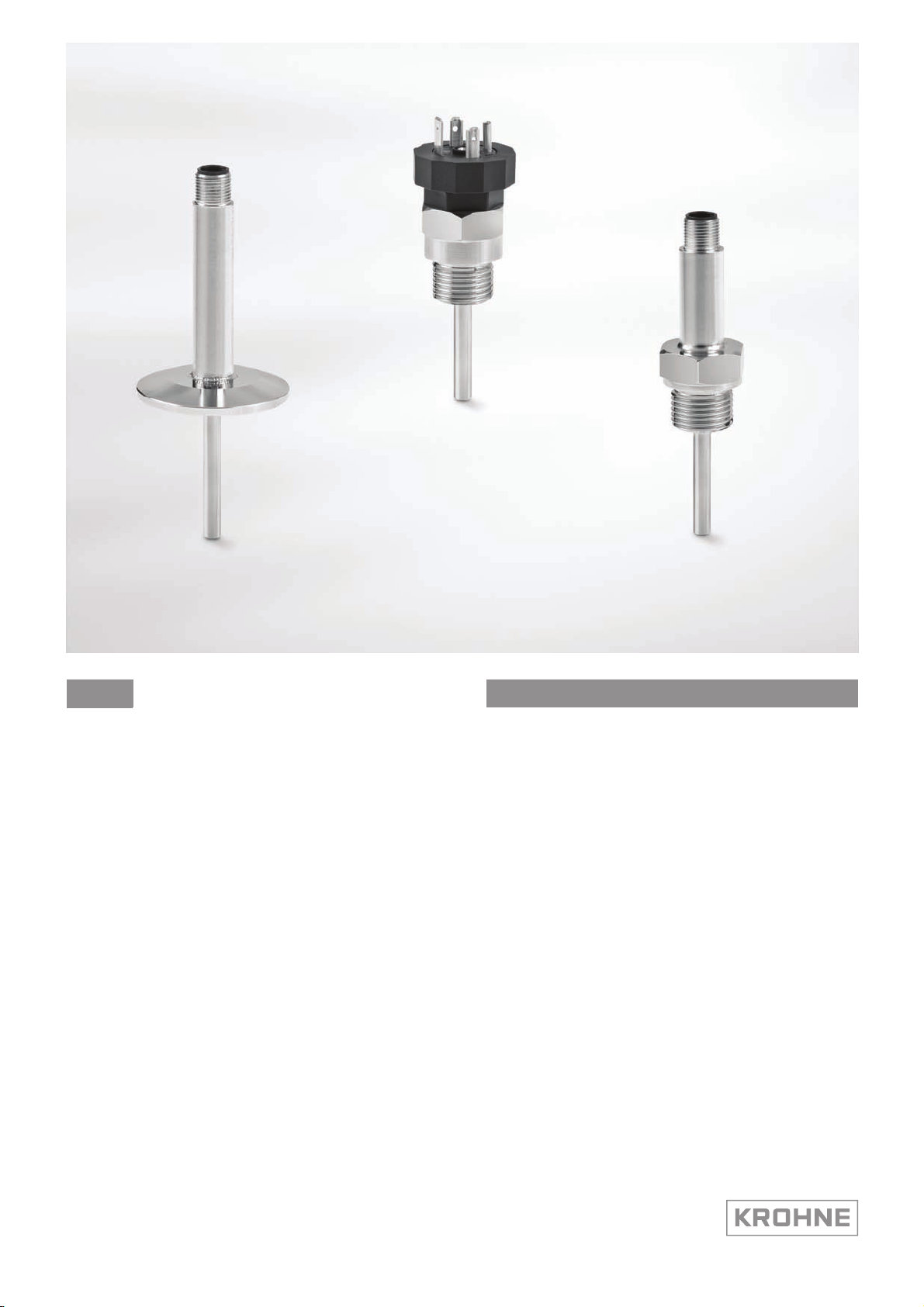
Industrial compact sensors
Handbook
Handbook
HandbookHandbook
© KROHNE 02/2014 - 4003290501 - MA OPTITEMP TRA-Cxx R01 en
Page 2

: IMPRINT :::::::::::::::::::::::::::::::::::::::
OPTITEMP TRA-CXX
All rights reserved. It is prohibited to reproduce this documentation, or any part thereof, without
the prior written authorisation of KROHNE Messtechnik GmbH.
Subject to change without notice.
Copyright 2014 by
KROHNE Messtechnik GmbH - Ludwig-Krohne-Str. 5 - 47058 Duisburg (Germany)
2
www.krohne.com 02/2014 - 4003290501 - MA OPTITEMP TRA-Cxx R01 en
Page 3

OPTITEMP TRA-CXX
CONTENTS
1 Safety instructions 5
1.1 Intended use ..................................................................................................................... 5
1.2 Approvals and certifications............................................................................................. 5
1.2.1 CE ............................................................................................................................................ 5
1.3 Safety instructions from the manufacturer ..................................................................... 5
1.3.1 Copyright and data protection ................................................................................................ 5
1.3.2 Disclaimer ............................................................................................................................... 6
1.3.3 Product liability and warranty ................................................................................................ 7
1.3.4 Information concerning the documentation........................................................................... 7
1.3.5 Warnings and symbols used................................................................................................... 8
1.4 Safety instructions for the operator................................................................................. 8
2 Device description 9
2.1 Scope of delivery............................................................................................................... 9
2.2 Device description .......................................................................................................... 10
2.2.1 Design of the compact sensors ............................................................................................10
2.2.2 Types of electrical connections ............................................................................................ 11
2.2.3 Types of temperature transmitters ...................................................................................... 12
2.2.4 Housing ................................................................................................................................. 13
2.2.5 Thermowells ......................................................................................................................... 13
2.3 Process connections and areas of application .............................................................. 14
2.3.1 Threaded sensor ................................................................................................................... 14
2.3.2 Flange sensor ....................................................................................................................... 14
2.4 Overview of available versions ....................................................................................... 15
2.5 Nameplate ...................................................................................................................... 16
3 Installation 17
3.1 General notes on installation ......................................................................................... 17
3.2 Storage ........................................................................................................................... 17
3.3 Transport ........................................................................................................................ 17
3.4 Proper installation.......................................................................................................... 17
3.4.1 Possible installations............................................................................................................ 18
3.4.2 Other installation requirements........................................................................................... 19
3.5 Load limits ...................................................................................................................... 20
3.5.1 Vibration load ........................................................................................................................ 20
3.5.2 Temperature load ................................................................................................................. 20
3.6 Installation notes on the individual device classes........................................................ 22
3.6.1 Threaded compact sensor .................................................................................................... 22
3.6.2 Flange sensor ....................................................................................................................... 23
4 Electrical connections 24
4.1 Safety instructions.......................................................................................................... 24
4.2 Electrical connection of M12 connector......................................................................... 25
4.3 Electrical connection of Valve EN 175301-803 connector ............................................. 26
4.4 Grounding ....................................................................................................................... 27
4.5 Protection category ........................................................................................................27
www.krohne.com02/2014 - 4003290501 - MA OPTITEMP TRA-Cxx R01 en
3
Page 4

CONTENTS
OPTITEMP TRA-CXX
4.6 Power supply .................................................................................................................. 27
5 Operation 28
5.1 Start-up........................................................................................................................... 28
5.2 Normal operation ...........................................................................................................28
5.3 Faults and damage: reason and remedies .................................................................... 28
6 Service 30
6.1 Cleaning and maintenance............................................................................................. 30
6.2 Availability of services .................................................................................................... 30
6.3 Returning the device to the manufacturer..................................................................... 30
6.3.1 General information.............................................................................................................. 30
6.3.2 Form (for copying) to accompany a returned device............................................................ 31
6.4 Disposal .......................................................................................................................... 31
7 Technical data 32
7.1 Measuring principle........................................................................................................32
7.1.1 Resistance temperature sensor ........................................................................................... 32
7.2 Technical data tables ..................................................................................................... 33
7.3 Dimensions ..................................................................................................................... 36
7.3.1 Compact sensors .................................................................................................................. 36
7.4 Measuring accuracy ....................................................................................................... 39
7.5 Process connections ...................................................................................................... 39
7.6 Sensor response time .................................................................................................... 40
8 Appendix 41
8.1 Technical legislation in effect ........................................................................................ 41
9 Notes 42
4
www.krohne.com 02/2014 - 4003290501 - MA OPTITEMP TRA-Cxx R01 en
Page 5

OPTITEMP TRA-CXX
1.1 Intended use
CAUTION!
Responsibility for the use of the measurement devices with regard to suitability, intended use
and corrosion resistance of the used materials against the measured fluid lies solely with the
operator.
INFORMATION!
The manufacturer is not liable for any damage resulting from improper use or use for other than
the intended purpose.
The compact sensors are used to measure the temperature of gases, liquids, vapour and solids
in industrial applications with limited installation space. The devices are particularly suited to
the measurement of
• liquids with low viscosity
• water and chemicals with low corrosiveness
1.2 Approvals and certifications
SAFETY INSTRUCTIONS 1
1.2.1 CE
Article 1, section 2.1.4 of the Pressure Equipment Directive 97/23/EC does not apply to compact
thermometers. For this reason, neither a conformity assessment nor a CE marking is possible.
The EC directives applicable to temperature transmitters are contained in transmitter part of
this documentation.
1.3 Safety instructions from the manufacturer
1.3.1 Copyright and data protection
The contents of this document have been created with great care. Nevertheless, we provide no
guarantee that the contents are correct, complete or up-to-date.
The contents and works in this document are subject to copyright. Contributions from third
parties are identified as such. Reproduction, processing, dissemination and any type of use
beyond what is permitted under copyright requires written authorisation from the respective
author and/or the manufacturer.
The manufacturer tries always to observe the copyrights of others, and to draw on works created
in-house or works in the public domain.
The collection of personal data (such as names, street addresses or e-mail addresses) in the
manufacturer's documents is always on a voluntary basis whenever possible. Whenever
feasible, it is always possible to make use of the offerings and services without providing any
personal data.
We draw your attention to the fact that data transmission over the Internet (e.g. when
communicating by e-mail) may involve gaps in security. It is not possible to protect such data
www.krohne.com02/2014 - 4003290501 - MA OPTITEMP TRA-Cxx R01 en
5
Page 6

1 SAFETY INSTRUCTIONS
completely against access by third parties.
We hereby expressly prohibit the use of the contact data published as part of our duty to publish
an imprint for the purpose of sending us any advertising or informational materials that we have
not expressly requested.
1.3.2 Disclaimer
The manufacturer will not be liable for any damage of any kind by using its product, including,
but not limited to direct, indirect or incidental and consequential damages.
This disclaimer does not apply in case the manufacturer has acted on purpose or with gross
negligence. In the event any applicable law does not allow such limitations on implied warranties
or the exclusion of limitation of certain damages, you may, if such law applies to you, not be
subject to some or all of the above disclaimer, exclusions or limitations.
Any product purchased from the manufacturer is warranted in accordance with the relevant
product documentation and our Terms and Conditions of Sale.
The manufacturer reserves the right to alter the content of its documents, including this
disclaimer in any way, at any time, for any reason, without prior notification, and will not be liable
in any way for possible consequences of such changes.
OPTITEMP TRA-CXX
6
www.krohne.com 02/2014 - 4003290501 - MA OPTITEMP TRA-Cxx R01 en
Page 7

OPTITEMP TRA-CXX
1.3.3 Product liability and warranty
The operator shall bear responsibility for the suitability of the device for the specific purpose.
The manufacturer accepts no liability for the consequences of misuse by the operator. Improper
installation and operation of the devices (systems) will cause the warranty to be void. The
respective "Standard Terms and Conditions" which form the basis for the sales contract shall
also apply.
1.3.4 Information concerning the documentation
To prevent any injury to the user or damage to the device it is essential that you read the
information in this document and observe applicable national standards, safety requirements
and accident prevention regulations.
If this document is not in your native language and if you have any problems understanding the
text, we advise you to contact your local office for assistance. The manufacturer can not accept
responsibility for any damage or injury caused by misunderstanding of the information in this
document.
This document is provided to help you establish operating conditions, which will permit safe and
efficient use of this device. Special considerations and precautions are also described in the
document, which appear in the form of underneath icons.
SAFETY INSTRUCTIONS 1
www.krohne.com02/2014 - 4003290501 - MA OPTITEMP TRA-Cxx R01 en
7
Page 8
1 SAFETY INSTRUCTIONS
1.3.5 Warnings and symbols used
Safety warnings are indicated by the following symbols.
DANGER!
This information refers to the immediate danger when working with electricity.
DANGER!
This warning refers to the immediate danger of burns caused by heat or hot surfaces.
DANGER!
This warning refers to the immediate danger when using this device in a hazardous atmosphere.
DANGER!
These warnings must be observed without fail. Even partial disregard of this warning can lead to
serious health problems and even death. There is also the risk of seriously damaging the device
or parts of the operator's plant.
OPTITEMP TRA-CXX
WARNING!
Disregarding this safety warning, even if only in part, poses the risk of serious health problems.
There is also the risk of damaging the device or parts of the operator's plant.
CAUTION!
Disregarding these instructions can result in damage to the device or to parts of the operator's
plant.
INFORMATION!
These instructions contain important information for the handling of the device.
LEGAL NOTICE!
This note contains information on statutory directives and standards.
• HANDLING
HANDLING
HANDLINGHANDLING
This symbol designates all instructions for actions to be carried out by the operator in the
specified sequence.
i RESULT
RESULT
RESULTRESULT
This symbol refers to all important consequences of the previous actions.
1.4 Safety instructions for the operator
WARNING!
In general, devices from the manufacturer may only be installed, commissioned, operated and
maintained by properly trained and authorized personnel.
This document is provided to help you establish operating conditions, which will permit safe and
efficient use of this device.
8
www.krohne.com 02/2014 - 4003290501 - MA OPTITEMP TRA-Cxx R01 en
Page 9

OPTITEMP TRA-CXX
2.1 Scope of delivery
INFORMATION!
Inspect the cartons carefully for damages or signs of rough handling. Report damage to the
carrier and to the local office of the manufacturer.
INFORMATION!
Do a check of the packing list to make sure that you have all the elements given in the order.
INFORMATION!
Look at the device nameplate to ensure that the device is delivered according to your order.
The manufacturer delivers all industrial temperature sensors with the relevant technical
documentation. The following table illustrates which sensor is delivered with which
documentation (HB = Handbook):
Scope of order HB for temperature sensors HB for transmitters
DEVICE DESCRIPTION 2
Compact sensor without
transmitter
Compact sensor with built in
transmitter
Compact sensor with rail mount
transmitter
X -
X -
X X
www.krohne.com02/2014 - 4003290501 - MA OPTITEMP TRA-Cxx R01 en
9
Page 10
2 DEVICE DESCRIPTION
2.2 Device description
2.2.1 Design of the compact sensors
INFORMATION!
In this documentation, the term "compact sensor" refers to all temperature assemblies
featuring with/without built-in transmitter.
OPTITEMP TRA-CXX
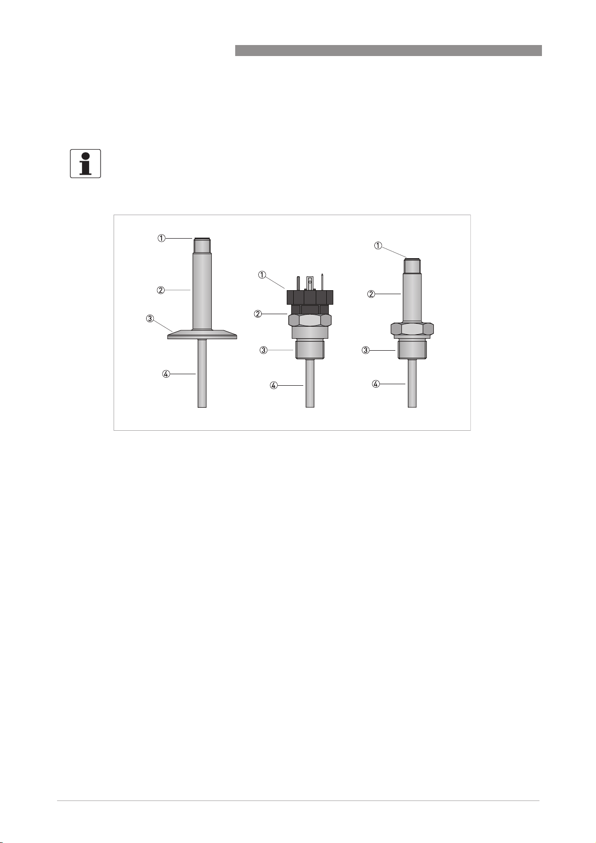
Figure 2-1: Design of all compact sensors
1 Electrical connection
2 Housing
3 Process connection
4 Thermowell
OPTITEMP compact sensors consist of a measuring probe with a process connection and a neck
tube with an electrical connection at the end. The sensors are avaiable with a built in
transmitter.
The transmitter linearizes to measured value to a 4… 20mA output and has a built in failure
mode, loop.
10
www.krohne.com 02/2014 - 4003290501 - MA OPTITEMP TRA-Cxx R01 en
Page 11

OPTITEMP TRA-CXX
2.2.2 Types of electrical connections
Electrical connections protects the temperature transmitter from environmental effects
(e. g. dirt or dust). They are available as:
• M12 connector
• Valve EN 175301-803 connector
Electrical connections available
M12 connector
M12 connector Valve EN 175301-803 connector
M12 connectorM12 connector
DEVICE DESCRIPTION 2
Valve EN 175301-803 connector
Valve EN 175301-803 connectorValve EN 175301-803 connector
www.krohne.com02/2014 - 4003290501 - MA OPTITEMP TRA-Cxx R01 en
11
Page 12

2 DEVICE DESCRIPTION
2.2.3 Types of temperature transmitters
Electrical temperature assemblies have just one, weak, interference-prone output signal. If this
signal has to travel a great distance or if a standard signal of 4...20 mA is required, use of a
temperature transmitter is recommended:
INFORMATION!
The manufacturer cannot make any general statement as to the distance from which the use of a
temperature transmitter is necessary as it depends on the specific interference associated with
the installation site. The operator alone is responsible for this decision.
There are two types of temperature transmitters:
• Built-in transmitter: Located in the housing of the temperature assembly
• Rail-mounted transmitter: Located in the control cabinet or field housing, recognisable by
the "R" in the product name (e. g. TT 50 R); they are usually used when the temperature in the
connection head does not allow for the use of a head-mounted transmitter
Built in transmitters
Built in transmitters
Built in transmittersBuilt in transmitters
OPTITEMP TRA-CXX
The built-in transmitters convert the temperature sensor's small signal into a standardised
output signal of 4...20 mA, not susceptible to interference. Which built in transmitter that is used
depends on the choice of the sensor.
The temperature range is set at factory:
• 0... +100°C / +32... +212°F
• -50... +150°C / -58... +302°F
Other temperature ranges are available on request.
Rail mounted transmitters
Rail mounted transmitters
Rail mounted transmittersRail mounted transmitters
You can parameterise almost any temperature transmitter using a PC and a computer program.
The only exceptions are the TT 10 R and TT 11 R versions, whose measuring ranges must be set
using solder bridges. The following temperature transmitters are currently available:
Available rail mounted transmitters
TT 10 R (analogue, 4...20 mA)
TT 11 R (analogue 3-wire transmitter, output: 0...10 VDC)
TT 30 R (digital, 4...20 mA)
TT 31 R (digital, 4...20 mA, 1- & 2-channel)
TT 32 R (digital 4-wire, outputs: 0/4...20 mA, 0/1...5 VDC, 0/2...10 VDC)
TT 40 R (digital, 4...20 mA, precise)
12
TT 50 R (digital, 4...20 mA, HART®)
TT 51 R (digital, 4...20 mA, HART®, SIL2, precise)
TT 60 R (digital, Profibus-PA)
www.krohne.com 02/2014 - 4003290501 - MA OPTITEMP TRA-Cxx R01 en
Page 13

OPTITEMP TRA-CXX
INFORMATION!
Consult the relevant transmitter handbook for more detailed information on the rail mountesd
temperature transmitters.
2.2.4 Housing
The housing connects the process connection (i.e. screw socket or flange) to the electrical
contact. Its function is to thermally decouple the connection and transmitter so the ambient
temperature doesn't exceed the permissible limits.
The materials of the housing and the thermowell are identical.
2.2.5 Thermowells
The thermowell is designed to prevent external loads (e. g. static pressure, flowing and
aggressive media) from damaging the sensor element. As a rule, the thermowell is made of the
same material as the system in which the measuring is done. The thermowell is built up from
multiple part and welded together.
DEVICE DESCRIPTION 2
www.krohne.com02/2014 - 4003290501 - MA OPTITEMP TRA-Cxx R01 en
13
Page 14

2 DEVICE DESCRIPTION
2.3 Process connections and areas of application
2.3.1 Threaded sensor
The gas tight threaded process connection is suitable for general applications with none or low
pressure. Can be mounted on pipes or tanks like in the chemical industry and into a solid part as
in the equipment industry. Depending on the application there are several types of threads and
standards to consider.
2.3.2 Flange sensor
The ISO 2852 Stainless steel clamp is a pipe coupling for the food and beverage industry. It is an
international standard defining a non-permanent hygienic piping interconnect method. Mainly
used in the food processing industry and with dairy farm equipment. The connection is built up
with a flange on the instrument and a counter flange in the pipe or tank. Between the flanges a
polymer sealing gasket fitting is placed. An enclosing clamp covers the outer circumference of
the flange to squeeze the two flanges together and with help of the gasket make a tight and solid
connection.
This clamp connection makes it easy to connect and disconnect without any special tools,
suitable for processes where continues cleaning is required like the food and beverage industry.
Companies that supply products according to the specifications of ISO 2852 do not necessarily
mention the ISO standard as such, instead referring to the equipment by terms common in the
relevant industries or applications like Tri-clamp or S-clamp.
OPTITEMP TRA-CXX
14
www.krohne.com 02/2014 - 4003290501 - MA OPTITEMP TRA-Cxx R01 en
Page 15

OPTITEMP TRA-CXX
2.4 Overview of available versions
INFORMATION!
The beginning of the product name refers to the type of sensor in the temperature assembly:
•
TRA: Sensor with Pt100, RTD
•
C: Compact series
TRA-C10
TRA-C10 TRA-C20
TRA-C10TRA-C10
TRA-C20 TRA-C30
TRA-C20TRA-C20
DEVICE DESCRIPTION 2
TRA-C30
TRA-C30TRA-C30
www.krohne.com02/2014 - 4003290501 - MA OPTITEMP TRA-Cxx R01 en
15
Page 16

2 DEVICE DESCRIPTION
2.5 Nameplate
INFORMATION!
Look at the device nameplate to ensure that the device is delivered according to your order.
The nameplate is located on the housing, it measures 42.4 mm x 8.5 mm / 1.67" x 0.33":
OPTITEMP TRA-CXX
TRA-CXX
Figure 2-2: Sample nameplate
1 Type of compact sensor
2 Production Order
3 Part number
4 Individual serial number
5 Manufacturer
6 Production site
7 Manufacturer's website
8 Range
9 Output
10 Note that the handbook is available for download from the manufacturer's website
11 CE Marking
12 WEEE Marking
PN: XXXXXXXXXX
SN: Nyyww.XXXXXX
PO: XXXXXXXXX
Range: XXXXXXXXXX
Output: XXXXXXXXXXX
Malmö, SWEDEN
www.krohne.com
INFORMATION!
For a customer-specific TAG No., the manufacturer can print out a separate label if required.
16
www.krohne.com 02/2014 - 4003290501 - MA OPTITEMP TRA-Cxx R01 en
Page 17

OPTITEMP TRA-CXX
3.1 General notes on installation
CAUTION!
Installation, assembly, start-up and maintenance may only be performed by appropriately
trained personnel. The regional occupational health and safety directives must always be
observed.
INFORMATION!
Inspect the cartons carefully for damages or signs of rough handling. Report damage to the
carrier and to the local office of the manufacturer.
INFORMATION!
Do a check of the packing list to make sure that you have all the elements given in the order.
INFORMATION!
Look at the device nameplate to ensure that the device is delivered according to your order.
INSTALLATION 3
INFORMATION!
Assembly materials and tools are not part of the delivery. Use the assembly materials and tools
in compliance with the applicable occupational health and safety directives.
3.2 Storage
CAUTION!
Always store industrial temperature assemblies in a dry place protected from dust. The
permissible range for storage temperatures is -40...+70
3.3 Transport
CAUTION!
Always transport industrial temperature assemblies in their original packaging. Do not expose
the devices to moisture or vibration during transport. The information that applies to storage
also applies to transport.
3.4 Proper installation
CAUTION!
Take the following points into consideration prior to installing the temperature assembly:
•
The dimensions of the thermowell (length, diameter, wall thickness, type of tip) comply with
the requirements of the measuring point. The mechanical load as a result of flowing media,
vibration and resonances is the focus here. In addition, incorrect dimensions can lead to
measurement errors.
•
The thermowell is sufficiently resistant to chemically aggressive media (refer to the generally
accessible corrosion tables). Otherwise, corrosion may occur or the medium may penetrate
into the thermowell. When in doubt, select a thermowell made from the same material as
your system.
°
C / -40...+176°F.
www.krohne.com02/2014 - 4003290501 - MA OPTITEMP TRA-Cxx R01 en
17
Page 18

3 INSTALLATION
3.4.1 Possible installations
Installations include the parameters "installation site", "installation angle" and "insertion
length". Depending on the space available and the diameter of the pipe, three installations are
recommended for pipes with flowing product:
• Small pipe diameter: Installation directly against the direction of flow in a bend in the
pipe (1).
• Small pipe diameter: Installation diagonally against the direction of flow, if a bend in the pipe
is available (2).
• Large pipe diameter: Vertical installation, if flow-induced periodic vortex shedding does not
cause the thermometer to vibrate in its resonance frequency (3).
OPTITEMP TRA-CXX
Figure 3-1: Recommended installations
18
www.krohne.com 02/2014 - 4003290501 - MA OPTITEMP TRA-Cxx R01 en
Page 19

OPTITEMP TRA-CXX
Permitted insertion length of the thermowell or measuring insert
Permitted insertion length of the thermowell or measuring insert
Permitted insertion length of the thermowell or measuring insertPermitted insertion length of the thermowell or measuring insert
The "insertion length" of the thermowell or measuring insert refers to the distance from the seal
of the process connection (for G threads) or the bottom of the flange (for flange thermometers)
to the tip of the thermowell or sheath. This length determines how far the sensor projects into
the measured medium.
To avoid measurement errors, ensure that the insertion length ("b" in the drawing below) meets
the following requirement:
• Tubes with Ø < 300 mm / 11.8": thermowell tip should project past the middle of the pipe is
possible, if the flow velocity of the product allows it.
INSTALLATION 3
Figure 3-2: Permitted insertion length
3.4.2 Other installation requirements
DANGER!
When a seal is damaged or incorrect, the medium may leak out, causing material damage or
bodily harm! It is the sole responsibility of the operator to select the right seal.
• A well-insulated pipeline or tank around the measuring point reduces the heat transfer and
the distorting influence of the ambient temperature.
• To avoid measurement errors caused by poor heat transfer, the measuring insert must
always be in contact with the bottom of the thermowell (this is normally guaranteed by filling
the thermowell with heat conducted compound).
• Choosing the right gasket for the process connection depends on the process conditions; the
manufacturer can thus only give the general recommendation that the gasket must comply
with the individual requirements of the measuring point (e.g. pressure, temperature,
chemically aggressive media, hygienic requirements).
www.krohne.com02/2014 - 4003290501 - MA OPTITEMP TRA-Cxx R01 en
19
Page 20

3 INSTALLATION
3.5 Load limits
The load limits of compact sensors depend on several factors:
• Dimensions and design of the measuring tip (especially the insertion length and diameter)
• Tip material
• Mechanical conditions the tip is subject to due to the measured medium (pressure,
temperature, flow velocity, viscosity, density)
• Sealable pressure of the process connection
• Vibration load
INFORMATION!
The "sealable pressure" is the maximum pressure the process connection can seal against.
The sheer number of factors at play illustrates the difficulty in making universally valid
statements about the load limits. For further information, please contact the manufacturer.
OPTITEMP TRA-CXX
3.5.1 Vibration load
CAUTION!
Permanently operating the sensor tip in its natural resonance can quickly damage or destroy the
temperature assembly! So, prior to installation, ensure that this does not happen and select a
sensor tip with a different length, a different diameter or another material if necessary.
All industrial temperature assemblies that feature an insert and neck tube and are attached to
the process connection have two components that can vibrate: the insert and the neck tube with
the neck tube. That is why the terms "insert resonance" and "neck tube resonance" are
commonly heard.
An insert surrounded by the measured medium is a body behind which vortices periodically are
released ("Kármán vortex street"). If the frequency of the vortex detachment is equal to the
resonance frequency of the thermowell, it starts to vibrate. If this happens for a short period of
time, such as when starting up the system and the frequency of the vortex detachment passes
through the resonance range of the thermowell, there is generally no damage is caused. The
opposite is true, however, if the vibrations remain permanently in the resonance range.
3.5.2 Temperature load
The temperature of the measured medium and the thermal dissipation via thermowell and neck
tube also cause the connection to heat up. After some time, the interior of the neck tube and any
existing transmitter heat up to the temperature of the neck tube.
This occurs in thermometers with and without neck tubes. A neck tube, however, causes thermal
decoupling and can prevent the connection or temperature transmitter from overheating at high
process temperatures.
20
CAUTION!
When the temperature is too high, the connection and the components found in the neck tube
(e. g. temperature transmitter) can be damaged or destroyed! It is your responsibility as the
operator to ensure that the connection and transmitter does not get too hot. If this does happen,
select another installation site or a longer neck tube.
www.krohne.com 02/2014 - 4003290501 - MA OPTITEMP TRA-Cxx R01 en
Page 21

OPTITEMP TRA-CXX
CAUTION!
Sometimes even a neck tube cannot prevent the maximum permissible temperature in the
transmitter or electrical connection from being exceeded! It does cause extensive thermal
decoupling of the connection but you still have to always take into consideration the installation
situation as well as the ambient and process temperatures!
INFORMATION!
For more information regarding the maximum allowable temperatures, please refer to the
"Technical Data" section.
INSTALLATION 3
www.krohne.com02/2014 - 4003290501 - MA OPTITEMP TRA-Cxx R01 en
21
Page 22

3 INSTALLATION
3.6 Installation notes on the individual device classes
3.6.1 Threaded compact sensor
A threaded compact sensor can be installed two different ways:
• Screwed in directly: Pipes with a wall thickness ≥ 20 mm / 0.8" make it possible to drill a hole
and cut a thread.
• Screw into threaded sleeves: Pipes with a wall thickness < 20 mm / 0.8" require a sleeve to be
welded in; these are not included in delivery but make up part of the accessories range.
OPTITEMP TRA-CXX
Figure 3-3: Compact sensor for direct screw-in
1 Housing
2 Threading into application's wall
3 Thermowell
CAUTION!
You, the user, are responsible for selecting a suitable sealing material for the process
connection, not the manufacturer! When installing the seals to the process connection, always
ensure a good fit!
CAUTION!
Sometimes even a neck tube cannot prevent the maximum permissible temperature in the
connection head from being exceeded! It does cause extensive thermal decoupling of the
connection head but you still have to always take into consideration the installation situation as
well as the ambient and process temperatures!
22
www.krohne.com 02/2014 - 4003290501 - MA OPTITEMP TRA-Cxx R01 en
Page 23

OPTITEMP TRA-CXX
3.6.2 Flange sensor
The compact flange sensor can be installed using a ISO 2852 DN25/38 clamp, for example, as
shown in the following drawing:
INSTALLATION 3
Figure 3-4: Installing a compact sensor with a ISO 2852 DN25/38 clamp
1 Housing
2 ISO 2852 DN25/38 clamp
3 Application wall
CAUTION!
You, the user, are responsible for selecting a suitable sealing material for the process
connection, not the manufacturer! When installing the seals to the process connection, always
ensure a good fit!
www.krohne.com02/2014 - 4003290501 - MA OPTITEMP TRA-Cxx R01 en
23
Page 24

4 ELECTRICAL CONNECTIONS
4.1 Safety instructions
DANGER!
All work on the electrical connections may only be carried out with the power disconnected. Take
note of the voltage data on the nameplate!
DANGER!
Observe the national regulations for electrical installations!
WARNING!
Observe without fail the local occupational health and safety regulations. Any work done on the
electrical components of the measuring device may only be carried out by properly trained
specialists.
INFORMATION!
Look at the device nameplate to ensure that the device is delivered according to your order.
OPTITEMP TRA-CXX
24
www.krohne.com 02/2014 - 4003290501 - MA OPTITEMP TRA-Cxx R01 en
Page 25

OPTITEMP TRA-CXX
ELECTRICAL CONNECTIONS 4
4.2 Electrical connection of M12 connector
Electrical connection with transmitter
Electrical connection with transmitter
Electrical connection with transmitterElectrical connection with transmitter
1
2
43
-
+
1 Out
2 M12-connector front view
3 R
Load
Electrical connection without transmitter
Electrical connection without transmitter
Electrical connection without transmitterElectrical connection without transmitter
423
www.krohne.com02/2014 - 4003290501 - MA OPTITEMP TRA-Cxx R01 en
25
Page 26

4 ELECTRICAL CONNECTIONS
4.3 Electrical connection of Valve EN 175301-803 connector
Electrical connection with transmitter
Electrical connection with transmitter
Electrical connection with transmitterElectrical connection with transmitter
1
3
2
-
+
OPTITEMP TRA-CXX
1 I
Out
2 Grounding not connected
3 R
Load
Electrical connection without transmitter
Electrical connection without transmitter
Electrical connection without transmitterElectrical connection without transmitter
312
26
www.krohne.com 02/2014 - 4003290501 - MA OPTITEMP TRA-Cxx R01 en
Page 27

OPTITEMP TRA-CXX
4.4 Grounding
DANGER!
The thermowells on the industrial temperature assemblies are grounded via the process
connection. No additional grounding is required.
4.5 Protection category
The IP protection category of an compact sensors depends on connection contact. When the
cable contact is connected properly the compact sensors TRA-C10 and TRA-C30 are available in
class IP67 and TRA-C20 in class IP65.
4.6 Power supply
INFORMATION!
Assembly materials and tools are not part of the delivery. Use the assembly materials and tools
in compliance with the applicable occupational health and safety directives.
ELECTRICAL CONNECTIONS 4
www.krohne.com02/2014 - 4003290501 - MA OPTITEMP TRA-Cxx R01 en
27
Page 28

5 OPERATION
5.1 Start-up
CAUTION!
Double check the following things prior to starting up an industrial compact sensor in order to
avoid measuring errors as well as damage to or the destruction of the compact sensor:
•
Ensure that the thermowells have been properly installed according to the manufacturer's
instructions.
•
Ensure that the process connection has been successfully tested for leaks.
•
Ensure that the measuring insert has been properly electrically connected according to the
manufacturer's instructions (refer to measuring insert handbook).
5.2 Normal operation
WARNING!
Never touch the thermowell, neck tube or connection in operation without protective gloves!
These components can become very hot during operation and cause burns.
5.3 Faults and damage: reason and remedies
OPTITEMP TRA-CXX
INFORMATION!
The most probable cause of a fault is the sensor element itself and its electronic components.
The following issues come into question here:
•
Short circuit or open circuit
•
Insulation resistance too low
In addition, the following faults and damage may occur:
Liquid on the process connection
A damaged or incorrect seal can lead to a leak at the process connection. Should this occur,
replace the seal and ensure that the new one meets the individual requirements of the
measuring point (pressure, temperature, chemically aggressive media). It is the sole
responsibility of the operator of the device to select the right seal.
28
www.krohne.com 02/2014 - 4003290501 - MA OPTITEMP TRA-Cxx R01 en
Page 29

OPTITEMP TRA-CXX
Temperature indication too high or too low
When reference measurements result in an incorrect temperature indication, three causes
come into question:
• Severe heat transfer caused by too short insertion length of thermowell: the compact sensor
indicates a temperature that is too low when it is above the ambient temperature and one that
is too high when it is below the ambient temperature.
• Severe heat transfer via the process connection, the pipeline or the tank wall due to a lack of
insulation.
• Incorrect thermowell dimensions (diameter, wall thickness).
To keep the heat transfer to a minimum, either increase the insertion length of the compact
sensor or improve the insulation of the measuring point.
Damage to the thermowell and penetrating liquid
If the thermowell is not sufficiently resistant to chemically aggressive media, corrosion may
occur and the measured medium may penetrate. In case of doubt, choose a thermowell made of
the same material as the pipe or tank in which the medium is located.
OPERATION 5
Breaks or tears
It is possible for breaks or tears to occur due to the force of the media flowing against the
thermowell. It is also possible for vibrations in the resonance range to damage or destroy the
thermowell. Superimposition of the two causes or a combination of insufficient mechanical and
chemical resistance is also possible. The following are starting points for troubleshooting:
• Selection of a thermowell with different dimensions
• Change in neck tube length at critical head resonances
• Selection of a different installation site
www.krohne.com02/2014 - 4003290501 - MA OPTITEMP TRA-Cxx R01 en
29
Page 30

6 SERVICE
6.1 Cleaning and maintenance
As a rule, the temperature assemblies require no cleaning or maintenance. However,
depending on the conditions of use and the thermal and mechanical load, they can age. This is
true of both measuring inserts with Pt100 RTDs and measuring inserts with thermocouples.
As a result of the ageing process, the characteristics ("characteristic curve") can change. That
means that the relationship between the electrical resistance (measuring insert with Pt100 RTD)
or the thermovoltage (measuring insert with thermocouple) and the temperature changes. In
this case, calibration shows whether any deviations in measurement values are still within
permissible tolerances.
6.2 Availability of services
The manufacturer offers a range of services to support the customer after expiration of the
warranty. These include repair, maintenance, technical support and training.
INFORMATION!
For more precise information, please contact your local sales office.
OPTITEMP TRA-CXX
6.3 Returning the device to the manufacturer
6.3.1 General information
This device has been carefully manufactured and tested. If installed and operated in accordance
with these operating instructions, it will rarely present any problems.
CAUTION!
Should you nevertheless need to return a device for inspection or repair, please pay strict
attention to the following points:
•
Due to statutory regulations on environmental protection and safeguarding the health and
safety of our personnel, manufacturer may only handle, test and repair returned devices that
have been in contact with products without risk to personnel and environment.
•
This means that the manufacturer can only service this device if it is accompanied by the
following certificate (see next section) confirming that the device is safe to handle.
CAUTION!
If the device has been operated with toxic, caustic, flammable or water-endangering products,
you are kindly requested:
•
to check and ensure, if necessary by rinsing or neutralising, that all cavities are free from
such dangerous substances,
•
to enclose a certificate with the device confirming that is safe to handle and stating the
product used.
30
www.krohne.com 02/2014 - 4003290501 - MA OPTITEMP TRA-Cxx R01 en
Page 31

OPTITEMP TRA-CXX
6.3.2 Form (for copying) to accompany a returned device
Company: Address:
Department: Name:
Tel. no.: Fax no.:
Manufacturer's order no. or serial no.:
The device has been operated with the following medium:
SERVICE 6
This medium is: water-hazardous
toxic
caustic
flammable
We checked that all cavities in the device are free from such
substances.
We have flushed out and neutralized all cavities in the
device.
We hereby confirm that there is no risk to persons or the environment through any residual media
contained in the device when it is returned.
Date: Signature:
Stamp:
6.4 Disposal
CAUTION!
Disposal must be carried out in accordance with legislation applicable in your country.
www.krohne.com02/2014 - 4003290501 - MA OPTITEMP TRA-Cxx R01 en
31
Page 32

7 TECHNICAL DATA
7.1 Measuring principle
All of the temperature assemblies described here belong to the class known as "contact
temperature assemblies". Unlike "radiation temperature assemblies", these temperature
assemblies come into direct contact with the medium whose temperature they are to measure.
The type of measuring principle depends on the sensor that you combine with the transmitter.
Two different sensor types are available for transmitters, RTD and thermocouple. The RTD's
measuring principle are used in the compact sensors and described in the following subsection.
7.1.1 Resistance temperature sensor
The measuring insert with a temperature-sensitive sensor made from a platinum RTD, whose
value at 0°C / +32°F is 100 Ω. That is where the name "Pt100" comes from.
It is generally valid that the electric resistance of metals increases according to a mathematical
function as the temperature rises. This effect is taken advantage of by resistance temperature
sensors to measure temperature. The "Pt100" temperature sensors features a measuring
resistance with defined characteristics, standardised in IEC 60751. The same is true for the
tolerances. The average temperature coefficient of a Pt100 is 3.85 x 10
0...+100°C / +32...+212°F.
OPTITEMP TRA-CXX
-3K-1
in the range from
During operation, a constant current I (≤ 1 mA) flows through the Pt100 RTD, which brings about
a voltage drop U. The resistance R is calculated using Ohm's Law (R=U/I). As the voltage drop U
at 0°C / +32°F is 100 mV, the resulting resistance of the Pt100 temperature assembly is
100 Ω (100 mV / 1 mA = 100 Ω).
Figure 7-1: Pt100 resistance temperature sensor in 4-wire connection at 0°C / +32°F, schematic.
1 Pt100 RTD
2 Voltage meter
3 Current source
32
www.krohne.com 02/2014 - 4003290501 - MA OPTITEMP TRA-Cxx R01 en
Page 33

OPTITEMP TRA-CXX
7.2 Technical data tables
INFORMATION!
•
The following data is provided for general applications. If you require data that is more
relevant to your specific application, please contact us or your local sales office.
•
Additional information (certificates, special tools, software,...) and complete product
documentation can be downloaded free of charge from the website (Download Center).
Measuring system
Application range Measuring the temperature of gases, liquids, vapours and solid
Measuring principle Contact sensor
Measured value Temperature
Design
Modular design Industrial temperature sensors consist of several components which,
TECHNICAL DATA 7
bodies in industrial processes. The devices are particularly suited to
liquids with low viscosity, water and chemicals with low
corrosiveness as well as saturated steam and superheated steam.
together, form a thermometer assembly:
• Thermowell
• Housing
• Electrical connection
• Transmitter (built in or rail mounted )
Signal converter Built-in analog transmitter, OPTITEMP OEM 201
Sensor Pt100 RTD as thin layer (TF), class A with a characteristic according
Surface roughness(only valid for
TRA-C10)
Measuring range Refer to "Operating conditions".
Analogue or digital temperature transmitter in the TT family as railmount transmitter.
to DIN EN 60751.
Ra 0.8, Ra <0.8 electropolished available on request
Measuring accuracy
Reference conditions Ambient temperature: +23°C / +73.4°F (fluctuations due to air
Maximum measuring error More detailed information in the subsection "Measurement Error"
Long term stability for built-in
transmitter
Influence of ambient for bulit in
transmitter
Response time for built in
transmitter
pressure and density have no impact on measuring accuracy).
(also in the "Technical data" section). The maximum measurement
error also depends on the type of sensor:
• Sensor element with Pt100 RTD: measurement error in accordance
with tolerance class A, according to DIN EN 60751.
±0.1% of span per year
Max. of ±0.01°C or ±0.01% of span per °C
Max. of ±0.01°F or ±0.006% of span per °F
< 10 ms
www.krohne.com02/2014 - 4003290501 - MA OPTITEMP TRA-Cxx R01 en
33
Page 34

7 TECHNICAL DATA
Operating conditions
Load limits The load limits depend on several factors (e.g. dimensions, design
Temperature
Temperature
TemperatureTemperature
Process temperature Maximum -50...+200°C / -50...+392°F, depending on design and
Pre-configured temperature
ranges
Ambient temperature Maximum -40...+85°C / -40...+185°F, depending on media
Storage temperature -40...+70°C / -40...+158°F at 40...60% relative humidity.
Other conditions
Other conditions
Other conditionsOther conditions
Protection categories Following protection categories can be provided if the connection
Shock resistance: Acc. to IEC60068-2-31, test Ec
Vibrations resistance: Acc. to IEC60068-2-6, test Fc, 10-2000Hz, 4g
OPTITEMP TRA-CXX
and material of thermowell). The compact sensor TRA-C10 can
handle pressure up to 16 bar / 232 psia while TRA-C20 and TRA-C30
can handle pressures up to 40 bar / 580 psia. This applies only if the
sensor is mounted properly.
material.
-50...+150°C / -58...+302°F or 0...+100°C / 32... +212°F
(Other ranges available on request)
temperature, sensor design and material.
cable is properly connected:
OPTITEMP TRA-C10, TRA-C30: IP67
OPTITEMP TRA-C20: IP65
Installation conditions
Insertion angle 90° to the flow, directly against or diagonally against the flow.
Insertion length Recommendable: 10...15 x thermowell diameter for gas,
5...10 x thermowell diameter for liquids (short insertion lengths may
impair measuring accuracy).
Materials
Thermowells (including process
connection)
The metal materials of the thermowells, neck tubes, flanges and
threads as process connections are always identical:
Standard:
Standard:
Standard:Standard:
1.4404 / AISI 316 L (X2CrNiMo 17-12-2)
Process connections
Threaded thermometer Gastight thread acc. to ISO 228/1: G½, other sizes on request.
Attachment using welding sleeves. Starting at a wall thickness of
20 mm / 0.8", it is possible to screw in directly with thread in the pipe
Flange thermometer Acc. to ISO 2852: DN25/38, other sizes on request.
34
www.krohne.com 02/2014 - 4003290501 - MA OPTITEMP TRA-Cxx R01 en
Page 35

OPTITEMP TRA-CXX
Electrical connections
Power supply Only necessary when using a temperature transmitter and depends
Power consumption Only when using a temperature transmitter, typically 550 mW.
Electrical connection M12-connector (for TRA-C10 and TRA-C30) or Valve EN 175301-803
Current output
Current output
Current outputCurrent output
Output range Exists only when using a temperature transmitter, 4...20 mA
Error signal Sensor break: Upscale (>=21,0 mA)
Load Relevant only when using a temperature transmitter (typically
Other electrical characteristics
Other electrical characteristics
Other electrical characteristicsOther electrical characteristics
Galvanic isolation Relevant only when using a temperature external transmitter (see
Time constant More detailed information can be found in the subsection "Response
TECHNICAL DATA 7
on transmitter type, typically 24 VDC.
7.5...32VDC for the built-in transmitter.
(for TRA-C20)
Sensor short-circuit: Downscale (<=3,6 mA)
250 Ω).
transmitter handbook).
times" of the section "Technical data".
Approvals and certificates
Electromagnetic compatibility For bulit in transmitter EN 61326-1
CE The device fulfils the statutory requirements of the EC directives. The
ESD, Radiated EM-field: Criteria A,
Surge: max 3% of span during disturbance influence
Burst and Conducted RF: max 1% of span during disturbance
influence
For external transmitter, refer to handbook for used temperature
transmitter.
Manufacturer certifies that these requirements have been met by
applying the CE marking.
www.krohne.com02/2014 - 4003290501 - MA OPTITEMP TRA-Cxx R01 en
35
Page 36

7 TECHNICAL DATA
7.3 Dimensions
7.3.1 Compact sensors
The dimensions for the compact sensors given in this subsection are standard measurements.
Upon request the manufacturer can supply devices with other dimensions.
OPTITEMP TRA-C10
OPTITEMP TRA-CXX
c
a
b
Figure 7-2: Dimensions of OPTITEMP TRA-C10
d
e
TRA-C10
"a" (insertion
length)
"b" (thermowell
diameter)
"c" (housing
length)
"d" (housing
diameter)
"e" (flange
diameter)
[mm] ["] [mm] ["] [mm] ["] [mm] ["] [mm] ["]
50 1.97 6 0.24 73 2.87 13.5 0.53 50.5 1.99
100 3.94 6 0.24 73 2.87 13.5 0.53 50.5 1.99
50 1.97 6 0.24 88 3.46 13.5 0.53 50.5 1.99
100 3.94 6 0.24 88 3.46 13.5 0.53 50.5 1.99
36
www.krohne.com 02/2014 - 4003290501 - MA OPTITEMP TRA-Cxx R01 en
Page 37

OPTITEMP TRA-CXX
OPTITEMP TRA-C20
TECHNICAL DATA 7
c
a
Figure 7-3: Dimensions of OPTITEMP TRA-C20
d
b
TRA-C20
"a" (insertion length) "b" (thermowell
diameter)
"c" (housing length) "d" (thread
dimension)
[mm] ["] [mm] ["] [mm] ["] [mm] ["]
50 1.97 6 0.24 35.5 1.40 G1/2" G1/2"
100 3.94 6 0.24 35.5 1.40 G1/2" G1/2"
www.krohne.com02/2014 - 4003290501 - MA OPTITEMP TRA-Cxx R01 en
37
Page 38

7 TECHNICAL DATA
OPTITEMP TRA-C30
OPTITEMP TRA-CXX
c
a
b
Figure 7-4: Dimensions of OPTITEMP TRA-C30
d
e
TRA-C30
"a" (insertion
length)
"b" (thermowell
diameter)
"c" (housing
length)
"d" (housing
diameter)
"e" (thread
dimension)
[mm] ["] [mm] ["] [mm] ["] [mm] ["] [mm] ["]
50 1.97 6 0.24 56 2.2 13.5 0.53 G1/2" G1/2"
100 3.94 6 0.24 56 2.2 13.5 0.53 G1/2" G1/2"
50 1.97 6 0.24 72 2.83 13.5 0.53 G1/2" G1/2"
100 3.94 6 0.24 72 2.83 13.5 0.53 G1/2" G1/2"
38
www.krohne.com 02/2014 - 4003290501 - MA OPTITEMP TRA-Cxx R01 en
Page 39

OPTITEMP TRA-CXX
7.4 Measuring accuracy
The measuring accuracy depends largely on the following factors:
• The type of the measuring sensor (type of circuit, measuring range).
• The correct dimensions (diameter, wall thickness) and insertion length of the thermowell for
good thermal coupling to the process temperature (insufficient insertion depth often results
in measurement errors).
• The type of temperature transmitter used.
INFORMATION!
Please consult the appropriate handbook for further information regarding the accuracy of the
external temperature transmitters.
With the exception of the TT 60 R version, all of the temperature transmitters generate an
analogue output signal. For this reason, the following table indicates the measuring accuracy of
most of the transmitters as a percentage of the measuring range. The measuring accuracy of the
RTD sensor without transmitter is class A according to IEC 60751.
TECHNICAL DATA 7
Temperature transmitter
Type of temperature transmitter Accuracy (% of the measuring range or °K)
Built-in transmitter OPTITEMP OEM 201 (analogue,
4...20 mA)
TT 10 R (analogue, 4...20 mA) ± 0.15%
TT 11 R (analogue 3-wire transmitter, output:
0...10 VDC)
TT 30 R (digital, 4...20 mA) ± 0.10%
TT 31 R (digital, 4...20 mA, 1- & 2-channel) ± 0.10%
TT 32 R (digital 4-wire, outputs: 0/4...20 mA,
0/1...5 VDC, 0/2...10 VDC)
TT 40 R (digital, 4...20 mA, precise) ± 0.05%
TT 50 R (digital, 4...20 mA, HART®)
TT 51 R (digital, 4...20 mA, HART®, SIL2, precise)
TT 60 R (digital, Profibus-PA) ± 0.10°K
7.5 Process connections
Threaded compact sensor
Process connection Ø of thermowell (material 1.4404 / 316 L)
± 0.15%
± 0.15%
± 0.10%
± 0.10%
± 0.05%
[mm] ["]
Thread G½" 6 0.24
Flange compact sensor
Process connection Ø of thermowell (material 1.4404 / 316 L)
[mm] ["]
ISO 2852 Clamp DN25/38 6 0.24
www.krohne.com02/2014 - 4003290501 - MA OPTITEMP TRA-Cxx R01 en
39
Page 40

7 TECHNICAL DATA
7.6 Sensor response time
Sensor response times are generally indicated as "50% time" (t05) and "90% time" (t09). "50%
time" refers to the time needed for a temperature sensor signal to achieve 50% of its end value
in the face of erratic temperature changes (this applies analogously to "90% time").
INFORMATION!
You can find more information about response times in VDI 3522.
Compact sensor with thermowell, with measuring element Pt100 RTD
Ø of thermowell Water with 0.4 m/s or 1.31 ft/s
[mm] ["] t05[s] t09[s]
6 0.24 3.2 9.0
Water flows against the compact sensor at 0.4 m/s
or 1.31 ft/s
OPTITEMP TRA-CXX
The transmitter response time is <10 ms.
40
www.krohne.com 02/2014 - 4003290501 - MA OPTITEMP TRA-Cxx R01 en
Page 41

OPTITEMP TRA-CXX
8.1 Technical legislation in effect
Standard Title
VDE/VDI 3511 Technical temperature measurements
VDI/VDE 3522 Response time of contact temperature assemblies.
IEC 60751 Industrial platinum resistance thermometers and platinum temperature
sensors.
APPENDIX 8
www.krohne.com02/2014 - 4003290501 - MA OPTITEMP TRA-Cxx R01 en
41
Page 42

9 NOTES
OPTITEMP TRA-CXX
42
www.krohne.com 02/2014 - 4003290501 - MA OPTITEMP TRA-Cxx R01 en
Page 43

OPTITEMP TRA-CXX
NOTES 9
www.krohne.com02/2014 - 4003290501 - MA OPTITEMP TRA-Cxx R01 en
43
Page 44

KROHNE product overview
• Electromagnetic flowmeters
• Variable area flowmeters
• Ultrasonic flowmeters
• Mass flowmeters
• Vortex flowmeters
• Flow controllers
• Level meters
• Temperature meters
• Pressure meters
• Analysis products
• Products and systems for the oil & gas industry
• Measuring systems for the marine industry
Head Office KROHNE Messtechnik GmbH
Ludwig-Krohne-Straße 5
47058 Duisburg (Germany)
Tel.:+49 203 301 0
Fax:+49 203 301 103 89
info@krohne.com
© KROHNE 02/2014 - 4003290501 - MA OPTITEMP TRA-Cxx R01 en - Subject to change without notice.
The current list of all KROHNE contacts and addresses can be found at:
www.krohne.com
 Loading...