

KROHNE OPTISYS SLM 2100 Handbook

OPTISYS SLM 2100
OPTISYS SLM 2100
OPTISYS SLM 2100OPTISYS SLM 2100
Sludge level meter
Electronic Revision:
1.0.1
Original handbook
Handbook
Handbook
HandbookHandbook
© KROHNE 01/2017 - 4002737304 - MA OPTISYS SLM 2100 R04 en

:
IMPRINT
:::::::::::::::::::::::::::::::::::::::
All rights reserved. It is prohibited to reproduce this documentation, or any part thereof, without
the prior written authorisation of KROHNE Messtechnik GmbH.
Subject to change without notice.
Copyright 2017 by
KROHNE Messtechnik GmbH - Ludwig-Krohne-Str. 5 - 47058 Duisburg (Germany)
2
www.krohne.com 01/2017 - 4002737304 - MA OPTISYS SLM 2100 R04 en

OPTISYS SLM 2100
CONTENTS
1 Safety instructions 6
1.1 Software history ............................................................................................................... 6
1.2 Intended use ..................................................................................................................... 7
1.3 Certifications .................................................................................................................... 7
1.4 Safety instructions from the manufacturer ..................................................................... 8
1.4.1 Copyright and data protection ................................................................................................ 8
1.4.2 Disclaimer ............................................................................................................................... 8
1.4.3 Product liability and warranty ................................................................................................ 9
1.4.4 Information concerning the documentation........................................................................... 9
1.4.5 Warnings and symbols used................................................................................................. 10
1.5 Safety instructions for the operator............................................................................... 10
2 Device description 11
2.1 Scope of delivery............................................................................................................. 11
2.2 Device description .......................................................................................................... 12
2.3 Nameplate ...................................................................................................................... 14
3 Installation 15
3.1 General notes on installation ......................................................................................... 15
3.2 Storage and transport .................................................................................................... 15
3.3 Typical measuring point ................................................................................................. 16
3.4 Installation order............................................................................................................ 17
3.4.1 Mounting of the sludge level meter...................................................................................... 18
3.5 Installing the cleaning unit (optional) ............................................................................ 24
3.5.1 Installation of the water hose to cleaning unit..................................................................... 25
4 Electrical connections 27
4.1 Safety instructions.......................................................................................................... 27
4.2 Used abbreviations .........................................................................................................27
4.3 Description of electrical symbols................................................................................... 28
4.4 Important device-specific notes on electrical connection............................................. 29
4.5 Overview of cable connections ....................................................................................... 30
4.6 Overview of the terminal compartment ......................................................................... 31
4.7 Connecting the power supply......................................................................................... 32
4.8 Description and properties of the output and the input ................................................ 34
4.8.1 Current output ...................................................................................................................... 34
4.8.2 Control input (active)............................................................................................................. 35
4.9 Connection of output and input ...................................................................................... 36
4.9.1 Important notes..................................................................................................................... 36
4.9.2 Current output ...................................................................................................................... 37
4.9.3 Electrical connection of control inputs................................................................................. 38
4.10 Description and properties of the relays ..................................................................... 40
4.10.1 Connection of the relays ..................................................................................................... 41
4.11 Protection category ...................................................................................................... 42
www.krohne.com01/2017 - 4002737304 - MA OPTISYS SLM 2100 R04 en
3

CONTENTS
OPTISYS SLM 2100
5 Operation 43
5.1 Start-up and general remarks for configuration........................................................... 43
5.2 Switching on the power .................................................................................................. 44
5.3 Operating elements........................................................................................................ 45
5.4 Measuring page .............................................................................................................. 46
5.4.1 Navigating through the menus .............................................................................................47
5.5 Menu mode structure..................................................................................................... 51
5.6 Function tables ............................................................................................................... 52
5.6.1 Menu A, quick setup.............................................................................................................. 52
5.6.2 Menu B, test .......................................................................................................................... 52
5.6.3 Menu C, setup ....................................................................................................................... 53
5.7 Functions in detail .......................................................................................................... 58
5.7.1 Definition of positions and zones.......................................................................................... 59
5.7.2 Initial configuration in extended settings ............................................................................. 60
5.7.3 Measuring function ............................................................................................................... 61
5.7.4 Assignment of current outputs............................................................................................. 62
5.7.5 Measuring mode ................................................................................................................... 62
5.7.6 Definition of fluff and blanket concentration........................................................................ 63
5.7.7 Definition of settings in zone tracking mode........................................................................ 63
5.7.8 Rake guard / trigger input .................................................................................................... 64
5.7.9 Timer / start signal ............................................................................................................... 64
5.7.10 Maintenance switch ............................................................................................................ 64
5.7.11 Calibration........................................................................................................................... 65
5.7.12 Reference point calibration ................................................................................................ 68
5.7.13 Passwords........................................................................................................................... 68
5.7.14 Timeout function ................................................................................................................. 68
5.8 Status messages and diagnostic information................................................................ 69
5.8.1 Error category "Device failure" (bold "F") ............................................................................ 70
5.8.2 Error category "Application error" ( "F", not bold) .............................................................. 71
5.8.3 Error category "Information" (I) ........................................................................................... 71
5.8.4 Error category "Out of specification" (S) .............................................................................. 71
6 Service 72
6.1 Manual initiation of a measurement .............................................................................. 72
6.2 Maintenance ................................................................................................................... 72
6.2.1 Cleaning unit (optional)......................................................................................................... 74
6.3 Spare parts availability...................................................................................................75
6.4 Availability of services .................................................................................................... 75
6.5 Returning the device to the manufacturer..................................................................... 75
6.5.1 General information.............................................................................................................. 75
6.5.2 Form (for copying) to accompany a returned device............................................................ 76
6.6 Disposal .......................................................................................................................... 76
7 Technical data 77
7.1 Measuring principle........................................................................................................77
7.2 Technical data................................................................................................................. 78
7.3 Dimensions ..................................................................................................................... 81
4
www.krohne.com 01/2017 - 4002737304 - MA OPTISYS SLM 2100 R04 en

OPTISYS SLM 2100
CONTENTS
8 Notes 85
www.krohne.com01/2017 - 4002737304 - MA OPTISYS SLM 2100 R04 en
5
1
SAFETY INSTRUCTIONS
1.1 Software history
The "Electronic Revision" (ER) is consulted to document the revision status of electronic
equipment according to NE 53 for all devices. It is easy to see from the ER whether
troubleshooting or larger changes in the electronic equipment have taken place and how that
has affected the compatibility.
Changes and effect on compatibility
1 Downwards compatible changes and fault repair with no effect on operation (e.g. spelling
mistakes on display)
2-_ Downwards compatible hardware and/or software change of interfaces:
HART
®
H
P PROFIBUS
F Foundation Fieldbus
M Modbus
X all interfaces
3-_ Downwards compatible hardware and/or software change of inputs and outputs:
I Current output
F, P Frequency / pulse output
S Status output
C Control input
CI Current input
X all inputs and outputs
4 Downwards compatible changes with new functions
5 Incompatible changes, i.e. electronic equipment must be changed.
OPTISYS SLM 2100
INFORMATION!
In the table below, "x" is a placeholder for possible multi-digit alphanumeric combinations,
depending on the available version.
Release date Electronic revision Changes and
Documentation
compatibility
04/2013 ER 1.0.0 - MA OPTISYS SLM 2100
XX/2015 ER 1.0.1 4 MA OPTISYS SLM 2100
R02 en
R03 en
MA OPTISYS SLM 2100
R04 en
6
www.krohne.com 01/2017 - 4002737304 - MA OPTISYS SLM 2100 R04 en

OPTISYS SLM 2100
1.2 Intended use
The OPTISYS SLM 2100 sludge level meter is primarily designed for use in water and waste
water treatment plants. There it determines the sedimentation profile in clarifiers and sludge
thickeners and detects sludge blanket or fluff level. For this it measures the suspended solids
concentration and height of the sensor above ground as the sensor is lowered into the basin or
tank.
However, the design of the OPTISYS SLM 2100 makes it possible to use it in other applications
where reliable monitoring of interface or stratification in suspensions is necessary.
The OPTISYS SLM 2100 shall not be used in hazardous areas, which e.g. require Ex approvals. It
could ignite gases. Additionally, due to the sensors material, the meter shall not be used in
applications with a high concentration of salt (e.g. seawater). The device has been constructed
for indoor and outdoor use below the maximum altitude of 2000 m / 6562 ft.
By observing the operation instructions, national standards, safety requirements and accident
prevention regulations the residual risk is reduced to an acceptable level.
SAFETY INSTRUCTIONS
1
1.3 Certifications
CE marking
The device meets the essential requirements of the EU directives. The CE marking indicates the
conformity of the product with the union legislation applying to the product and providing for CE
marking.
For full information of the EU directives and standards and the approved certifications, please
refer to the EU declaration on the KROHNE website
www.krohne.com01/2017 - 4002737304 - MA OPTISYS SLM 2100 R04 en
7

1
SAFETY INSTRUCTIONS
1.4 Safety instructions from the manufacturer
1.4.1 Copyright and data protection
The contents of this document have been created with great care. Nevertheless, we provide no
guarantee that the contents are correct, complete or up-to-date.
The contents and works in this document are subject to copyright. Contributions from third
parties are identified as such. Reproduction, processing, dissemination and any type of use
beyond what is permitted under copyright requires written authorisation from the respective
author and/or the manufacturer.
The manufacturer tries always to observe the copyrights of others, and to draw on works created
in-house or works in the public domain.
The collection of personal data (such as names, street addresses or e-mail addresses) in the
manufacturer's documents is always on a voluntary basis whenever possible. Whenever
feasible, it is always possible to make use of the offerings and services without providing any
personal data.
OPTISYS SLM 2100
We draw your attention to the fact that data transmission over the Internet (e.g. when
communicating by e-mail) may involve gaps in security. It is not possible to protect such data
completely against access by third parties.
We hereby expressly prohibit the use of the contact data published as part of our duty to publish
an imprint for the purpose of sending us any advertising or informational materials that we have
not expressly requested.
1.4.2 Disclaimer
The manufacturer will not be liable for any damage of any kind by using its product, including,
but not limited to direct, indirect or incidental and consequential damages.
This disclaimer does not apply in case the manufacturer has acted on purpose or with gross
negligence. In the event any applicable law does not allow such limitations on implied warranties
or the exclusion of limitation of certain damages, you may, if such law applies to you, not be
subject to some or all of the above disclaimer, exclusions or limitations.
Any product purchased from the manufacturer is warranted in accordance with the relevant
product documentation and our Terms and Conditions of Sale.
The manufacturer reserves the right to alter the content of its documents, including this
disclaimer in any way, at any time, for any reason, without prior notification, and will not be liable
in any way for possible consequences of such changes.
8
www.krohne.com 01/2017 - 4002737304 - MA OPTISYS SLM 2100 R04 en

OPTISYS SLM 2100
1.4.3 Product liability and warranty
The operator shall bear responsibility for the suitability of the device for the specific purpose.
The manufacturer accepts no liability for the consequences of misuse by the operator. Improper
installation or operation of the devices (systems) will cause the warranty to be void. The
respective "Standard Terms and Conditions" which form the basis for the sales contract shall
also apply.
1.4.4 Information concerning the documentation
To prevent any injury to the user or damage to the device it is essential that you read the
information in this document and observe applicable national standards, safety requirements
and accident prevention regulations.
If this document is not in your native language and if you have any problems understanding the
text, we advise you to contact your local office for assistance. The manufacturer can not accept
responsibility for any damage or injury caused by misunderstanding of the information in this
document.
This document is provided to help you establish operating conditions, which will permit safe and
efficient use of this device. Special considerations and precautions are also described in the
document, which appear in the form of icons as shown below.
SAFETY INSTRUCTIONS
1
www.krohne.com01/2017 - 4002737304 - MA OPTISYS SLM 2100 R04 en
9

1
SAFETY INSTRUCTIONS
1.4.5 Warnings and symbols used
Safety warnings are indicated by the following symbols.
DANGER!
This warning refers to the immediate danger when working with electricity.
DANGER!
This warning refers to the immediate danger of burns caused by heat or hot surfaces.
DANGER!
This warning refers to the immediate danger when using this device in a hazardous atmosphere.
DANGER!
These warnings must be observed without fail. Even partial disregard of this warning can lead to
serious health problems and even death. There is also the risk of seriously damaging the device
or parts of the operator's plant.
OPTISYS SLM 2100
WARNING!
Disregarding this safety warning, even if only in part, poses the risk of serious health problems.
There is also the risk of damaging the device or parts of the operator's plant.
CAUTION!
Disregarding these instructions can result in damage to the device or to parts of the operator's
plant.
INFORMATION!
These instructions contain important information for the handling of the device.
LEGAL NOTICE!
This note contains information on statutory directives and standards.
• HANDLING
HANDLING
HANDLINGHANDLING
This symbol designates all instructions for actions to be carried out by the operator in the
specified sequence.
i RESULT
RESULT
RESULTRESULT
This symbol refers to all important consequences of the previous actions.
1.5 Safety instructions for the operator
10
WARNING!
In general, devices from the manufacturer may only be installed, commissioned, operated and
maintained by properly trained and authorized personnel.
This document is provided to help you establish operating conditions, which will permit safe and
efficient use of this device.
www.krohne.com 01/2017 - 4002737304 - MA OPTISYS SLM 2100 R04 en

OPTISYS SLM 2100
2.1 Scope of delivery
INFORMATION!
Inspect the packaging carefully for damages or signs of rough handling. Report damage to the
carrier and to the local office of the manufacturer.
INFORMATION!
Do a check of the packing list to make sure that you have all the elements given in the order.
INFORMATION!
Look at the device nameplate to ensure that the device is delivered according to your order.
Check for the correct supply voltage printed on the nameplate.
DEVICE DESCRIPTION
2
Figure 2-1: Scope of delivery
1 Sludge level meter (optional with cleaning unit and spray shield)
2 Key for cable drum lock and key for electronic compartment lock
3 Mounting accessories
4 Documentation
Optional accessories
Optional accessories
Optional accessoriesOptional accessories
• Mounting frame
• Rod steel U-bolts for round handrail
• Cleaning unit
www.krohne.com01/2017 - 4002737304 - MA OPTISYS SLM 2100 R04 en
11
2
DEVICE DESCRIPTION
2.2 Device description
OPTISYS SLM 2100
Figure 2-2: Device description of OPTISYS SLM 2100
1 Fan
2 Electronic compartment door with display
3 Cable drum compartment door
4 Guide roller and zero point reference switch
5 Sensor
6 4 x cable feedthrough M20
7 Cable drum with heating unit at the back
8 Pickup and axle board with optical interface
9 Safety switch
10 Main electronics and connectors
Main electronics unit
The main electronic unit is located in a separate compartment above the cable drum, which can
be accessed via a separate door with a key lock. It contains the mainboard and fan assembly. The
mainboard bears the main processor and all electrical connectors. It also controls all
mechanical and electrical events in the device and communicates with sensor, display and
keyboard. It additionally contains the current outputs and control inputs.
Fan assembly
The position of the fan is on the top right side of the enclosure. In combination with the heater
the instrument maintains suitable temperature conditions inside the enclosure of the meter.
DANGER!
The rotating fan blades can be accessed, when the electronic compartment door is open and
there is a risk of injury when rotating fan is touched.
12
www.krohne.com 01/2017 - 4002737304 - MA OPTISYS SLM 2100 R04 en

OPTISYS SLM 2100
Display and keyboard
Display and keyboard are located in the front door of the electronics compartment. Display and
keyboard are based on the GDC (general device concept), which means a common HMI (human
machine interface) to all KROHNE GDC instruments is provided. The keyboard consists of four
membrane keys and the display is a LCD graphic display with a resolution of 128 x 64 Pixel.
Cable drum assembly and heater unit
The cable drum helps to move the sensor up and down in the basin. It is mounted directly on the
motor shaft of a synchronous motor, hidden behind the drum mounting plate. The cable drum
always moves with a very constant speed. Since the diameter of the cable roll in the drum varies,
the speed of the sensor varies. That is why the sensor moves slower during the end of the
sampling. Due to the roll design, shortening of cable or movement of the metal sleeve on the
sensor cable is prohibited. This will lead to different diameter of the cable roll and finally
resulting in wrong results in the height/depth measurements. The heater unit is located behind
the drum mounting plate. In combination with the fan the instrument maintains suitable
temperature conditions inside the enclosure of the meter.
Guide roller and zero point reference switch
The guide roller helps to keep the cable in place during the measuring process. A stable height
measurement is reached by zero point reference switch. The inductive proximity switch reacts
on the metal sleeve on the sensor cable and calibrates the home position. Each time when
leaving the menu the device performs a zero point calibration. In addition a regular calibration
during the process can be performed time based via the setup.
DEVICE DESCRIPTION
2
Sensor
The sensor used in the OPTISYS SLM 2100 is a suspended solid sensor. The sensor contains a
near-infrared light source and a receiver in an angle of 180°. Both are positioned in such a way
that the emitted near-infrared light has to pass through the liquid before reaching the receiver.
The suspended solids in the liquid absorb the emitted light leading to a lower intensity at the
detector. The light loss is proportional to the suspended solid content.
Pickup board & axle board
The pickup board is mounted on a spring loaded lever arm and transfers power and
communication signals to the cable drum.
The axle board on the cable drum is powered contactless ("inductively") by the pickup board. It
communicates with the main electronics unit via the pickup board and with the sensor via an
optical interface.
Cable feedthroughs
The 4 M20 cable feedthroughs are for the connection of power, signal and control cables. Only
three cable feedthroughs can be used, if the optional cleaning unit is installed.
Safety switch
The safety switch located on the top left corner of the cable drum compartment is a protective
device, which de-energizes the motor when the front door is opened in order to avoid danger due
to moving parts inside the meter.
www.krohne.com01/2017 - 4002737304 - MA OPTISYS SLM 2100 R04 en
13
2
DEVICE DESCRIPTION
Cleaning unit (optional)
The cleaning unit, mounted under the device, consists of a valve and a spraying system to keep
the sensor and cable free of deposits ensuring low maintenance efforts of OPTISYS SLM 2100.
The cleaning unit uses water which can be supplied either by an external water source (process
water) or by water from the clear water phase. The latter can be performed by an external pump
which is controlled by the OPTISYS SLM 2100.
2.3 Nameplate
INFORMATION!
Look at the device nameplate to ensure that the device is delivered according to your order.
Check for the correct supply voltage printed on the nameplate.
OPTISYS SLM 2100
Figure 2-3: Example of a nameplate
1 Manufacturer
2 CE marking
3 Manufacturing year,
Electronic revision,
Power supply data
4 Protection categories
5 Observe the operation and installation instruction,
Electronic / electric device waste marking,
Data matrix code
6 Order code / TAG no.
7 Production order / Serial number
8 Device name
14
www.krohne.com 01/2017 - 4002737304 - MA OPTISYS SLM 2100 R04 en

OPTISYS SLM 2100
3.1 General notes on installation
INFORMATION!
Inspect the packaging carefully for damages or signs of rough handling. Report damage to the
carrier and to the local office of the manufacturer.
INFORMATION!
Do a check of the packing list to make sure that you have all the elements given in the order.
INFORMATION!
Look at the device nameplate to ensure that the device is delivered according to your order.
Check for the correct supply voltage printed on the nameplate.
INFORMATION!
The display should be mounted in a height of 1.5...1.8 m / 4.9...5.9 ft to prevent ergonomic
hazards.
INFORMATION!
During work on the device above the basin the personnel have to be protected by personal safety
equipment.
INSTALLATION
3
3.2 Storage and transport
• Store and transport the device in a dry, dust-free environment.
• Store and transport the device in an environment with a temperature between -20...+60°C/
-4...+140°F.
• The original packing is designed to protect the equipment. It has to be used if the device is
transported or sent back to the manufacturer including the sensor fixation inside the device,
to prevent damage of the sensor.
INFORMATION!
Due to the weight above 20 kg / 44.1 lbs please lift and carry the device only with two persons or
use appropriate lifting equipment and if the surfaces of the device are wet, please use gloves for
lifting.
www.krohne.com01/2017 - 4002737304 - MA OPTISYS SLM 2100 R04 en
15
3
INSTALLATION
3.3 Typical measuring point
OPTISYS SLM 2100
Figure 3-1: Example of typical measuring points
1 OPTISYS SLM 2100 with brackets for round handrail on horizontal post
2 OPTISYS SLM 2100 with brackets for rectangular handrail (not included of scope of delivery)
3 OPTISYS SLM 2100 mounted on a wall
4 Handrail
16
www.krohne.com 01/2017 - 4002737304 - MA OPTISYS SLM 2100 R04 en
OPTISYS SLM 2100
3.4 Installation order
DANGER!
Do not install the sludge level meter in hazardous areas, it can ignite explosive gases!
DANGER!
Do not cover or obstruct the ventilation. It can lead to overheating of the device.
INFORMATION!
The device must not be heated by radiated heat (e.g. exposure to the sun) to a electronics
housing surface temperature above the maximum permissible ambient temperature. If it is
necessary to prevent damage from heat sources, a heat protection (e.g. sun shade) has to be
installed.
INFORMATION!
The operator is responsible for providing, securing and the possibility of switching off the supply
voltage.
INSTALLATION
3
INFORMATION!
The external electrical main switch (red / yellow) of the device has to be located close to the
device and easily accessible. An internal main switch is not available.
INFORMATION!
The device should be located at save installation site in order to prevent the danger of falling in
the water basin. Furthermore, there should be enough space in front of the device ensuring an
easy access.
To install the measuring system in the best way, follow the steps described below.
Steps to install the meter
1 Mounting of the sludge level meter
(for detailed information refer to
2 Installing the cleaning unit (optional)
(for detailed information refer to
3 Connecting the power supply
(for detailed information refer to
4 Connection of the current outputs
(for detailed information refer to
5 Connecting the rake guard switch / external trigger or maintenance switch - if required
(for detailed information refer to
6 Configuration of the sludge level meter
(for detailed information refer to
7 Calibration of the sludge level meter
(for detailed information refer to
Mounting of the sludge level meter
Cleaning unit (optional)
on page 74)
Connecting the power supply
Current output
on page 37).
Electrical connection of control inputs
Functions in detail
Calibration
on page 65).
on page 58).
on page 18).
on page 32).
on page 38).
INFORMATION!
For decommissioning of the device please repeat the steps above in reverse order from 5 to 1.
www.krohne.com01/2017 - 4002737304 - MA OPTISYS SLM 2100 R04 en
17

3
INSTALLATION
3.4.1 Mounting of the sludge level meter
INFORMATION!
To ensure proper assembly, please use only the mounting material provided with the meter.
INFORMATION!
All bolts, nuts and washers should be greased to prevent cold welding and ensure simple
disassemble after use.
INFORMATION!
Please ask a second person to help with this procedure.
Due to many different applications and installation points of sludge level meter a standardised
mounting is often not applicable. To overcome the problem of the local conditions three different
opportunities exist to order the mounting of the sludge meter.
Available mounting possibilities
Available mounting possibilities
Available mounting possibilitiesAvailable mounting possibilities
OPTISYS SLM 2100
INFORMATION!
Ensure that the handrail is suitable for the weight of the mounting frame and the device
(standard: 26.5 kg / 58.4 lbs, with cleaning unit: 31kg / 68.3 lbs); otherwise support the handrail
with additional material. The operator is responsible for safe installation, especially against the
fall in the sedimentation basin.
18
www.krohne.com 01/2017 - 4002737304 - MA OPTISYS SLM 2100 R04 en

OPTISYS SLM 2100
Direct mounting without frame
Direct mounting without frame
Direct mounting without frameDirect mounting without frame
The sludge meter can be mounted directly on the wall. The sludge level meter has 4 M6 threads
on the back and on the bottom of the instrument. If the threads on the bottom are used, ensure
that there is enough space for sensor, cable feedthroughs and the cleaning unit. For further
information refer to
• Mount the meter using the 4 M6 screws
Dimensions
on page 81.
INSTALLATION
3
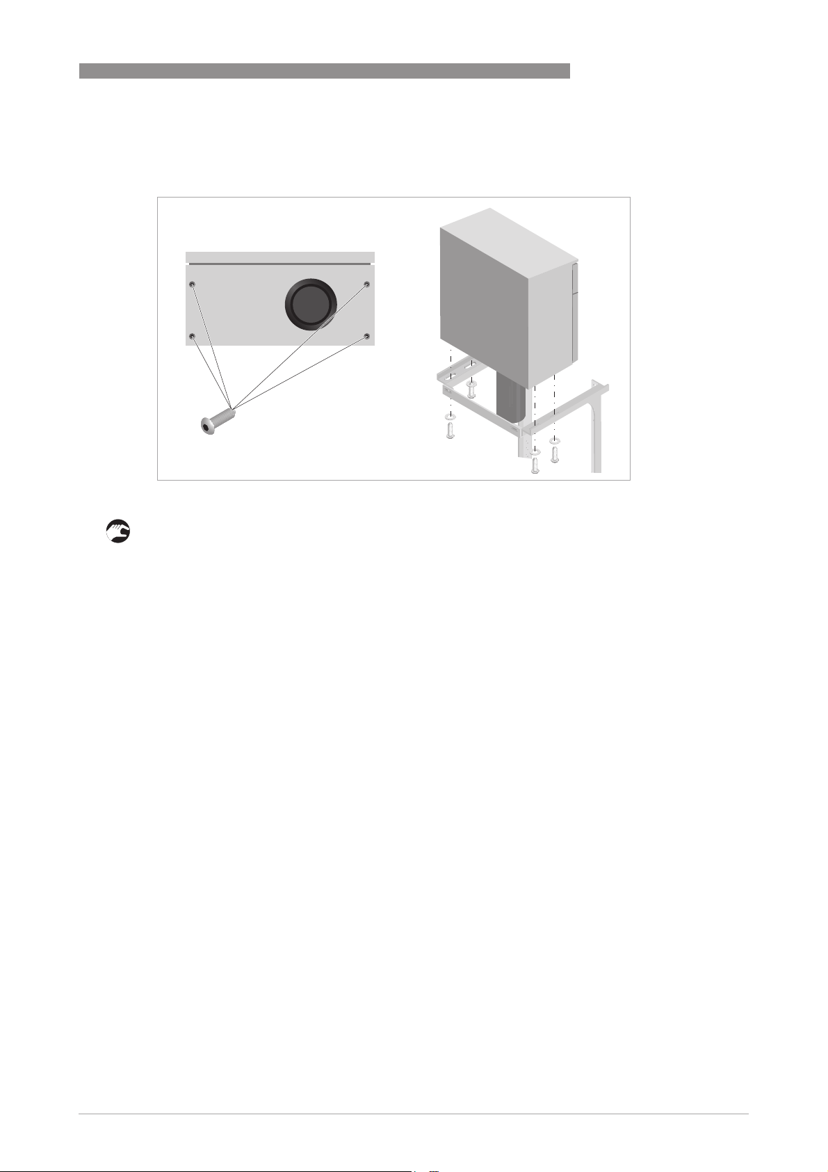
Figure 3-2: Mounting on wall
1 4 x M6 screws
2 Wall
3 OPTISYS SLM 2100
www.krohne.com01/2017 - 4002737304 - MA OPTISYS SLM 2100 R04 en
19
3
INSTALLATION
Mounting frame
Mounting frame
Mounting frameMounting frame
The mounting frame can be used for round or rectangular handrails. For rectangular handrails
suitable rectangular brackets should be selected which are not part of the scope of delivery. Use
at least 3 fixation points as described in the installation of round handrails. For further
information refer to
Mounting frame with brackets with round handrail (vertical or horizontal)
Mounting frame with brackets with round handrail (vertical or horizontal)
Mounting frame with brackets with round handrail (vertical or horizontal)Mounting frame with brackets with round handrail (vertical or horizontal)
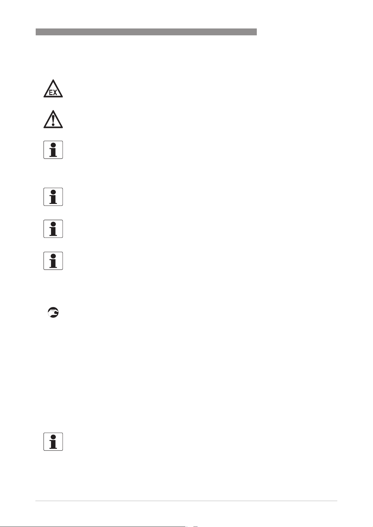
This option allows installing the sludge level meter on many round handrails. The rod steel Ubolts cover handrails between diameters of 33...60.3 mm / 1.3...2.37 inch. Two round rod steel Ubolts fixate the mounting frame on the upper handrail. A further rod steel U-bolt stabilises the
sludge level meter by fixation to a horizontal or vertical bar.
Mounting on round handrail with horizontal bar
Mounting on round handrail with horizontal bar
Mounting on round handrail with horizontal barMounting on round handrail with horizontal bar
Dimensions
OPTISYS SLM 2100
on page 81.
20
Figure 3-3: Mounting of upper handrail
1 Rod steel U-bolts
• Mount the frame using the rod steel U-bolts (M10) and nuts 1 in a position that the frame is
above the handrail.
www.krohne.com 01/2017 - 4002737304 - MA OPTISYS SLM 2100 R04 en
OPTISYS SLM 2100
Mounting on lower round handrail with horizontal bar
Mounting on lower round handrail with horizontal bar
Mounting on lower round handrail with horizontal barMounting on lower round handrail with horizontal bar
INSTALLATION
3
Figure 3-4: Mounting of lower handrail (horizontal)
1 Screws and nuts
2 Rod steel U-bolt
3 Adapter for lower handrail
• Find suitable and stable positions of the lower crossbars.
• Fix crossbars with screws (M8 x 20), nuts and washers 1.
• On both crossbars mount the adaption plate 3.
• Mount the rod steel U-bolt (M10) 2 to the horizontal pole with washers.
• Use the slot holes to adjust the respective height.
• Adjust the position of all brackets.
• Tighten all screws.
• Position the meter on the frame and tighten it with M6 screws.
www.krohne.com01/2017 - 4002737304 - MA OPTISYS SLM 2100 R04 en
21
3
INSTALLATION
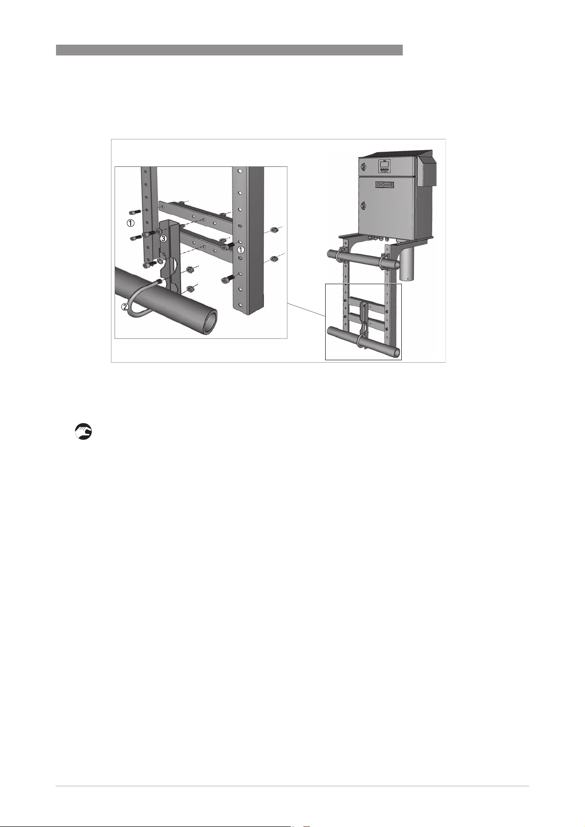
Mounting on lower round handrail with vertical bar
Mounting on lower round handrail with vertical bar
Mounting on lower round handrail with vertical barMounting on lower round handrail with vertical bar
OPTISYS SLM 2100
Figure 3-5: Mounting of lower handrail (vertical)
1 Screws and nuts
2 Rod steel U-bolt
3 Adapter for lower handrail
• Find suitable and stable positions of the lower crossbars.
• Fix crossbars with screws and nuts 1.
• On one crossbar mount the adaption plate 3.
• Mount the rod steel U-bolt 2 to the vertical pole.
• Adjust the position of all brackets.
• Tighten all screws.
• Position the meter on the frame and tighten it with M6 screws.
22
www.krohne.com 01/2017 - 4002737304 - MA OPTISYS SLM 2100 R04 en
OPTISYS SLM 2100
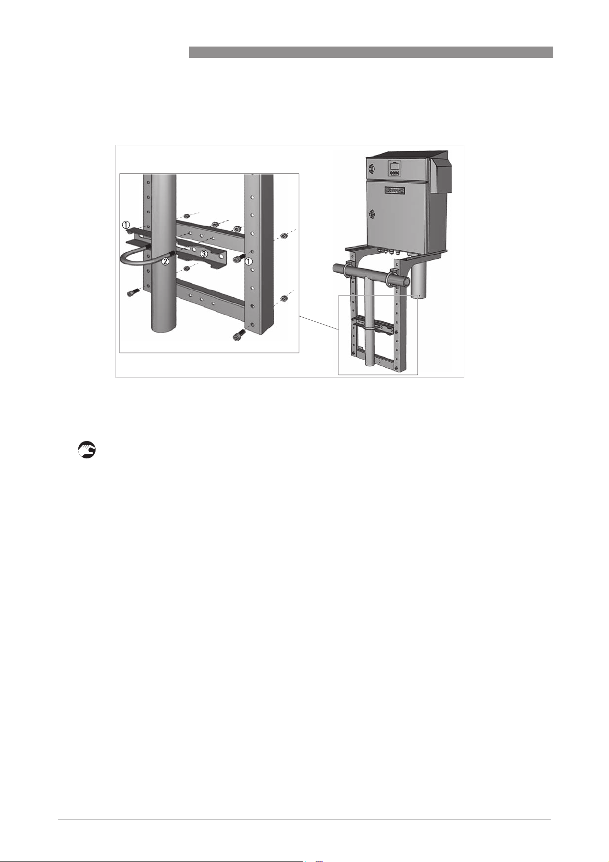
Fixing the meter
Fixing the meter
Fixing the meterFixing the meter
INSTALLATION
3
Figure 3-6: Mounting device on handrail
• Fix the meter to the upper part of the mounting frame using screws (M6 x 16) and washers
according to the drawing above.
• Please make sure that the meter is mounted in such a height that display and keyboard are at
eye level.
• Remove the sensor transportation protection to prevent blocking of the sensor.
www.krohne.com01/2017 - 4002737304 - MA OPTISYS SLM 2100 R04 en
23
3
INSTALLATION
3.5 Installing the cleaning unit (optional)
The cleaning unit, mounted under the device, consists of a valve and a spraying system to keep
the sensor and cable free of deposits ensuring low maintenance efforts of the device. The
cleaning unit is mounted and electrically connected to the device by the manufacturer with
exception of the spray shield and the water connection.
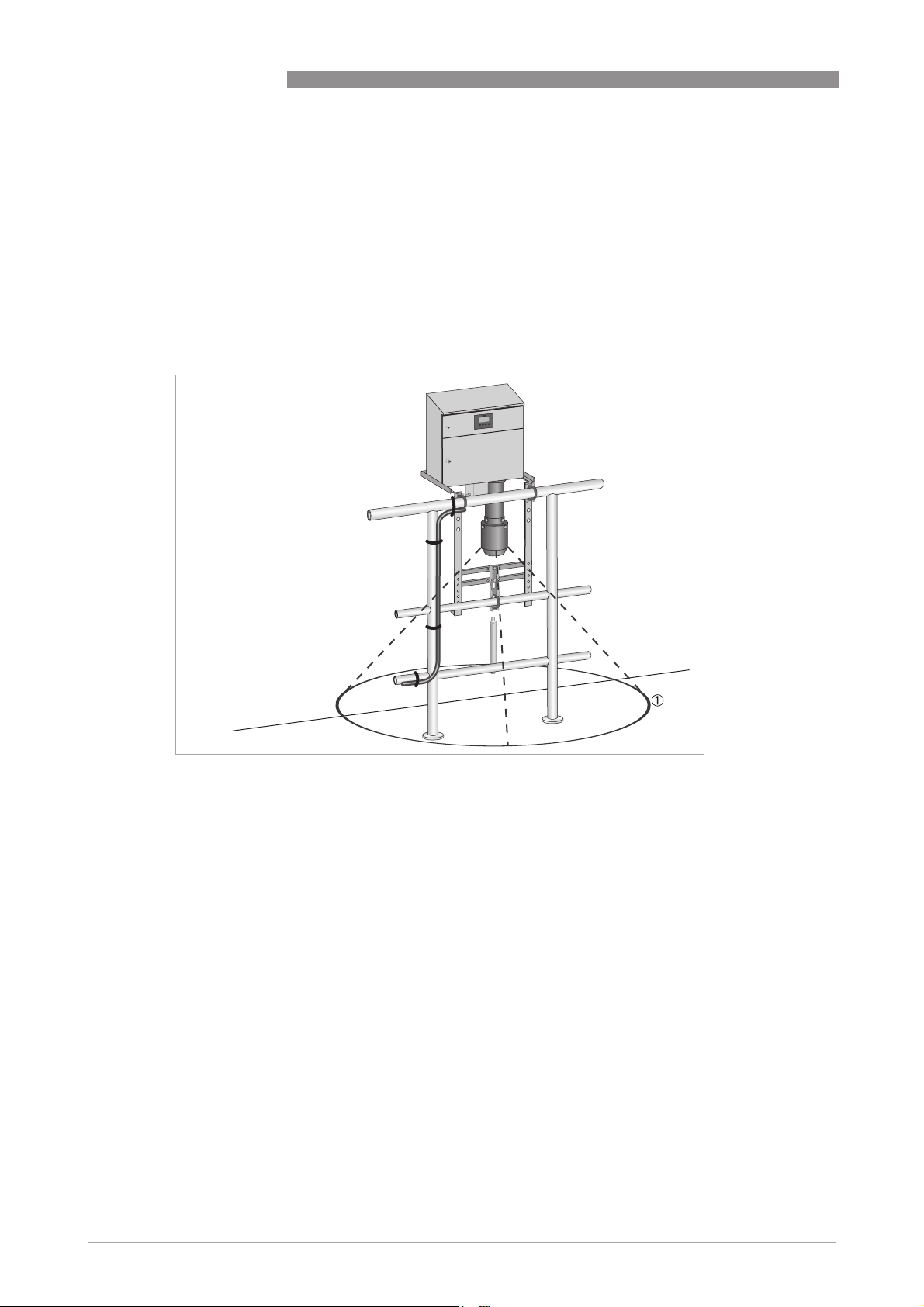
If installing a device containing a cleaning unit, keep a safety area around the sensor garage free
from electrical device or water sensitive parts, as outlined in the following drawing.
OPTISYS SLM 2100
Figure 3-7: Safety area
1 Radius: 2 m / 78.74"
The cleaning unit can be supplied with water by 2 options:
• External water supply by hose with drinking or process water.
• Water supplied by pumped clear water of the sedimentation basin. For further information
refer to
Description and properties of the relays
on page 40.
24
www.krohne.com 01/2017 - 4002737304 - MA OPTISYS SLM 2100 R04 en
OPTISYS SLM 2100
3.5.1 Installation of the water hose to cleaning unit
WARNING!
The maximum allowed water pressure should not exceed 6 bar / 87 psi.
INFORMATION!
An external separation switch of the water supply has to be located close to the device and easily
accessible.
A 3/4" male connector (Whitworth EN 10226) with metric thread provides the mounting junction
for the water hose adapter.
When installing the water hose adapter on the connector, carefully fix the nut of the fitting. The
electric valve inside the cleaning system housing may be twisted, which may cause water
leakage.
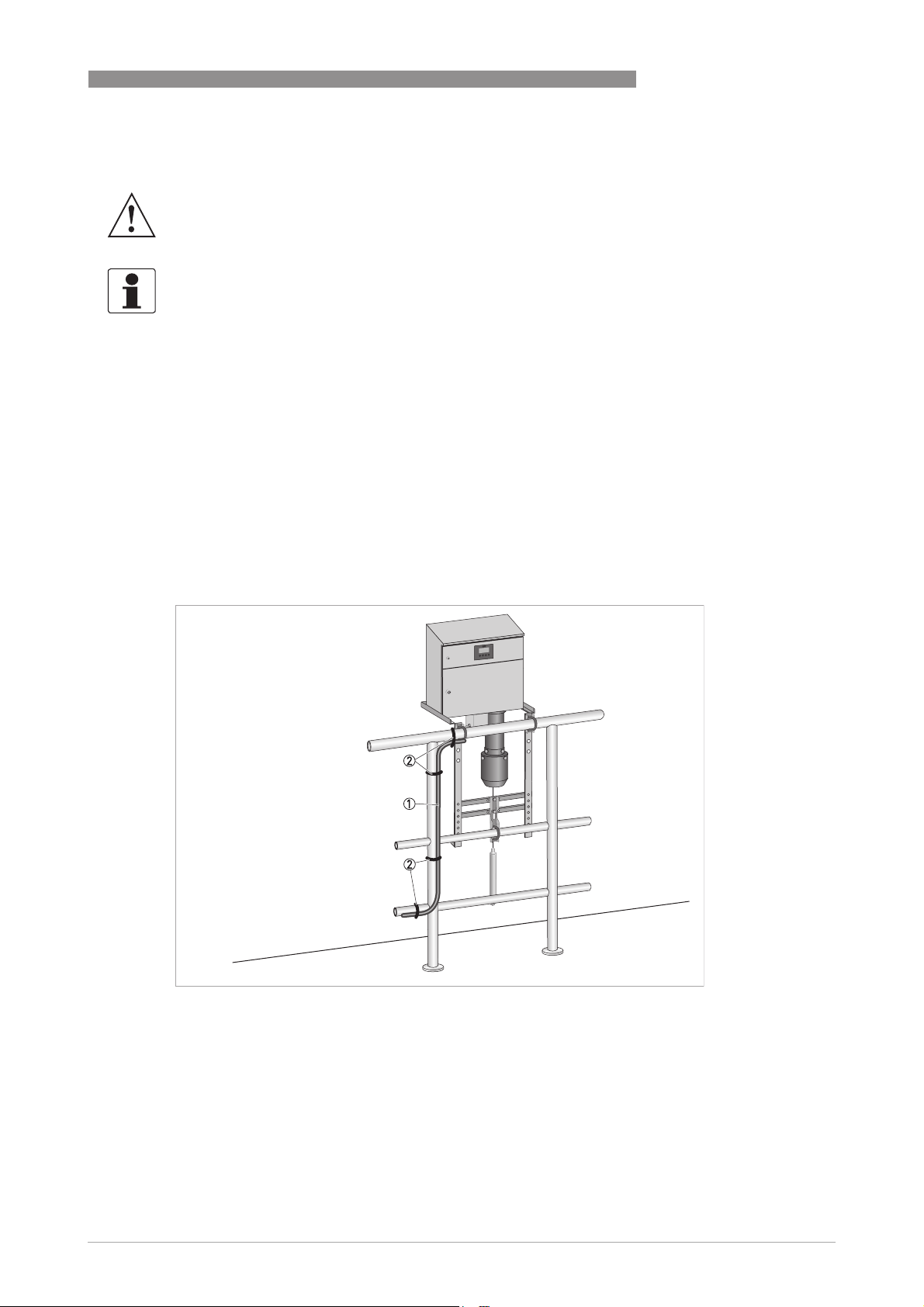
When installing the device, make sure the water hose is adequately fixed as outlined. Mount the
water hose in such a way that the weight of it is not carried by the hose adapter. When fixing the
hose also take into account that it must be avoided that it moves when the system is switched
on/off.
INSTALLATION
3
Figure 3-8: Fixing points water hose
1 Water hose
2 Fixing points
www.krohne.com01/2017 - 4002737304 - MA OPTISYS SLM 2100 R04 en
25
3
INSTALLATION
Mounting sprayshield
Mounting sprayshield
Mounting sprayshieldMounting sprayshield
Figure 3-9: Mounting sprayshield
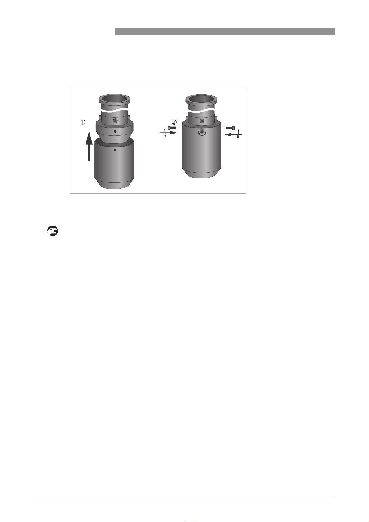
1 Push the sprayshield above the cleaning unit. Please be aware that the holes are align to each other.
2 Insert the 4 M6 screws.
OPTISYS SLM 2100
• The sprayshield has to be mounted by the operator using 4 M6 screws to the cleaning unit as
described in this drawing.
26
www.krohne.com 01/2017 - 4002737304 - MA OPTISYS SLM 2100 R04 en
OPTISYS SLM 2100
4.1 Safety instructions
DANGER!
All work on the electrical connections may only be carried out with the power disconnected. Take
note of the voltage data on the nameplate!
DANGER!
Observe the national regulations for electrical installations!
WARNING!
Observe without fail the local occupational health and safety regulations. Any work done on the
electrical components of the measuring device may only be carried out by properly trained
specialists.
WARNING!
Before performing any work on the device switch off the power and make sure that it cannot be
switched on accidently.
ELECTRICAL CONNECTIONS
4
INFORMATION!
Look at the device nameplate to ensure that the device is delivered according to your order.
Check for the correct supply voltage printed on the nameplate.
4.2 Used abbreviations
Abbreviation Description
CI
a
I
a
I
max
I
nom
R
L
P Power
U
int, nom
U
ext
U
o
VAC Alternating current (AC) voltage
CI Control input
PCS Process control system
NO Switch (normally open)
NC Switch (normally closed)
LED Light-emitting diode
K Relay
Control input active
Current output active
Maximum current
Nominal current
Load resistance
Nominal internal voltage
External voltage
Terminal voltage
www.krohne.com01/2017 - 4002737304 - MA OPTISYS SLM 2100 R04 en
27
 Loading...