

Page 1
Safety Manual
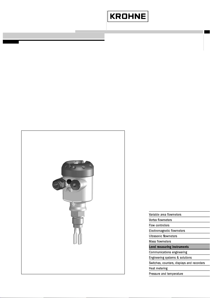
OPTISWITCH series 5000
- two-wire
Page 2

1 Content
Content
1 Functional safety
1.1 In general . . . . . . . . . . . . . . . . . . . . . . . . . . . . . . . .
1.2 Planning . . . . . . . . . . . . . . . . . . . . . . . . . . . . . . . . .
1.3 Adjustment instructions . . . . . . . . . . . . . . . . . . . . . . .
1.4 Setup. . . . . . . . . . . . . . . . . . . . . . . . . . . . . . . . . . . .
1.5 Reaction during operation and in case of failure . . . . .
1.6 Recurring function test . . . . . . . . . . . . . . . . . . . . . . .
1.7 Safety-related characteristics . . . . . . . . . . . . . . . . . . .
3
5
6
7
7
7
8
2 OPTISWITCH series 5000 • - two-wire
32750-EN-100128
Page 3
1 Functional safety
1.1 In general
1 Functional safety
Scope
Area of application
SIL conformity
Abbreviations, terms
This safety manual applies to measuring systems consisting of the
vibrating level switch OPTISWITCH series 5000 with integrated
oscillator SWE60Z:
OPTISWITCH 5100 C, 51 50 C, 5200 C, 5250 C
For instruments with enamelled fork, oscillator SWE60Z.E or SWE60Z.
E1 is required.
The measuring system can be implemented for level detection (of
liquids) which meets the special requirements of safety technology.
This is possible up to S IL2 in a single channel architecture (1oo1D),
and up to SIL3 in a multiple channel, redundant architecture.
The SIL declaration of conformity can be downloaded from our
homepage in the Internet.
SIL Safety Integrity Level
HFT Hardware Fault Tolerance
SFF Safe Failure Fraction
PFD
PFH Probability of a dangerous Failure per Hour
FMEDA Failure Mode, Effects and Diagnostics Analysis
λ
sd
λ
su
λ
dd
λ
du
DC
S
DC
D
FIT Failure In Time (1 FIT = 1 failure/10
MTBF Mean Time Between Failure
MTTF Mean Time To Failure
MTTR Mean Time To Repair
Average Probability of dangerous Failure on Demand
avg
Rate for safe detected failure
Rate for safe undetected failure
Rate for dangerous detected failure
Rate for dangerous undetected failure
Diagnostic Coverage of safe failures; DCS= λsd/(λsd+λsu)
Diagnostic Coverage of dangerous failures; DCD= λdd/(λdd+λdu)
9
h)
Further abbreviations and terms are stated in IEC 61508-4.
32750-EN-100128
OPTISWITCH series 5000 • - two-wire 3
Page 4

1 Functional safety
Relevant standards
Safety requirements
l IEC 61508
- Functional safety of electrical/electronic/programmable elec-
tronic safety-related systems
l IEC 61511-1
- Functional safety - safety instrumented systems for the
process industry sector - Part 1: Framework, definitions,
system, hardware and software requirements
Failure limit values for a safety function, depending on the SIL class (of
IEC 61508-1, 7.6.2)
Safety integrity level Low demand mode High demand mode
SIL PFD
4 ≥ 10
-5
… < 10
avg
3 ≥ 10-4… < 10
2 ≥ 10-3… < 10
1 ≥ 10-2… < 10
-4
-3
-2
-1
PFH
≥ 10-9… < 10
≥ 10-8… < 10
≥ 10-7… < 10
≥ 10-6… < 10
-8
-7
-6
-5
Safety integrity of the hardware for safety-related subsystems of type A
(IEC 61508-2, 7.4.3)
Safe failure fraction Hardware
SFF HFT = 0 HFT = 1 HFT = 2
< 60 % SIL1 SIL2 SIL3
60 % … < 90 % SIL2 SIL3 (SIL4)
90 % … < 99 % SIL3 (SIL4) (SIL4)
≥ 99 % SIL3 (SIL4) (SIL4)
fault tolerance
Service proven
According to IEC 61511-1, paragraph 11.4.4, the failure tolerance HFT
can be reduced by one for service-proven subsystems if the following
conditions are met:
l The instrument is service proven
l Only process-relevant parameters can be modified on the instru-
ment (e. g. measuring range, current output in case of failure …)
l The modification of these process-relevant parameters is pro-
tected (e. g. password, …)
l The safety function requires less than SIL4
The assessment by Change Management was a part of the "service
proven" verification.
4 OPTISWITCH series 5000 • - two-wire
32750-EN-100128
Page 5

1.2 Planning
1 Functional safety
Safety function
Safe state
Fault description
Configuration of the
processing unit
The safety function of this measuring system is the identification and
signalling of the condition of the vibrating element.
A difference is made between the two conditions "covered" and
"uncovered".
The safe state depends on the mode:
Overflow protection
(max. operation)
Vibrating element in safe
state
Output current in safe
state
Failure current "fail low" < 2.3 mA < 2.3 mA
Failure current "fail high" > 23.5 mA > 23.5 mA
covered uncovered
12.5 … 23.5 mA 2.3 … 11.5 mA
Dry run protection
(min. operation)
A safe failure exists when the measuring system switches to the
defined safe state or the fault mode without the process demanding it.
A dangerous undetected failure exists if the measuring system
switches neither to the defined safe condition nor to the failure mode
when the process requires it.
If the measuring system delivers output currents of "fail low" or "fail
high", it can be assumed that there is a malfunction.
The processing unit must therefore interpret such currents as a
malfunction and output a suitable fault signal.
If this is not the case, the corresponding portions of the failure rates
must be assigned to the dangerous failures. The stated values in
chapter "Safety-relevant characteristics" can thus worsen.
The processing unit must correspond to the SIL level of the
measurement chain.
Low demand mode
If the demand rate is only once a year, then the measuring system can
be used as safety-relevant subsystem in "low demand mode"
(IEC 61508-4, 3.5.12).
If the ratio of the internal diagnostics test rate of the measuring system
to the demand rate exceeds the value 100, the measuring system can
be treated as if it is executing a safety function in the mode with low
demand rate (IEC 61508-2, 7.4.3.2.5).
An associated characteristic is the value PFD
(average Probability
avg
of dangerous Failure on Demand). It is dependent on the test interval
between the function tests of the protective function.
T
Proof
32750-EN-100128
OPTISWITCH series 5000 • - two-wire 5
Page 6

1 Functional safety
Number values see chapter "Safety-related characteristics".
High demand mode
Assumptions
General instructions and
restrictions
If the "low demand rate" does not apply, the measuring system as
safety-relevant subsystem in "high demand mode" should be used
(IEC 61508-4, 3.5.12).
The fault tolerance time of the complete system must be higher than
the sum of the reaction times or the diagnostics test periods of all
components in the safety-related measurement chain.
An associated characteristic is the value PFH (failure rate).
Number values see chapter "Safety-related characteristics".
The following assumptions form the basis for the implementation of
FMEDA:
l Failure rates are constant, wear of the mechanical parts is not
taken into account
l Failure rates of external power supplies are not taken into account
l Multiple errors are not taken into account
l The average ambient temperature during the operating time is
40 °C (104 °F)
l The environmental conditions correspond to an average industrial
environment
l The lifetime of the components is around 8 to 12 years (IEC 61508-
2, 7.4.7.4, remark 3)
l The repair time (exchange of the measuring system) after an
nondangerous malfunction is eight hours (MTTR = 8 h)
l The processing unit can interprete "fail low" and "fail high" failures
as errors and trigger a suitable error message
l The scanning interval of a connected control and processing unit
is max. 1 hour, in order to react to dangerous, detectable errors
The measuring system should be used appropriately taking pressure,
temperature, density and chemical properties of the medium into
account.
The user-specific limits must be kept. The specifications of the
operating instructions manual must not be exceeded.
Keep in mind when using as dry run protection:
l Avoid buildup on the vibrating system (probably shorter proof test
intervals will be necessary)
l Avoid solids > 5 mm (0.2 in) stored in the medium
l Avoid foam generation with a density of > 0.5 g/cm³ (0.018 lbs/in³)
1.3 Adjustment instructions
Adjustment elements
6 OPTISWITCH series 5000 • - two-wire
Since the plant conditions influence the safety of the measuring
system, the adjustment elements must be set according to the
application:
l DIL switch for sensitivity adjustment
32750-EN-100128
Page 7

1 Functional safety
The function of the adjustment elements is described in the operating
instructions manual.
1.4 Setup
Mounting and installa-
tion
Reason and implementation
Take note of the mounting and installation instructions of the operating
instructions manual.
In the setup procedure, a check of the safety function by means of an
initial filling is recommended.
1.5 Reaction during operation and in case of
failure
The adjustment elements or device parameters must not be modified
during operation.
If modifications have to be made during operation, carefully observe
the safety functions.
Fault signals that may appear are described in the appropriate
operating instructions manual.
If faults or error messages are detected, the entire measuring system
must be shut down and the process held in a safe state by other
measures.
An exchange of the electronics is easily possible and is described in
the operating instructions manual.
If due to a detected failure the electronics or the complete sensor is
exchanged, the manufacturer must be informed (incl. a fault
description).
1.6 Recurring function test
The recurring function test is used to check the safety function, to
detect possible non-recognisable, dangerous faults. The function of
the measuring system must be checked in adequate intervals.
The operator is responsible for choosing the type of check. The time
intervals depend on the selected PFD
diagram in paragraph "Safety-related characteristics".
With high demand rate, a recurring function test is not requested in
IEC 61508. The function of the measuring system is demonstrated by
the frequent use of the system. In double channel architectures it is a
good idea to verify the redundancy through recurring function tests at
appropriate intervals.
The test must be carried out in a way that verifies the flawless
operation of the safety functions in conjunction with all system
components.
value according to chart and
avg
32750-EN-100128
OPTISWITCH series 5000 • - two-wire 7
Page 8

1 Functional safety
This is ensured by a controlled reaching of the response height during
filling. If filling up to the response height is not possible, then a
response of the measuring system must be triggered by a suitable
simulation of the level or the physical measuring effect.
The methods and procedures used during the tests must be stated
and their suitability must be specified. The tests must be documented.
If the function test proves negative, the entire measuring system must
be switched out of service and the process held in a safe state by
means of other measures.
In the double channel architecture (1oo2D) this applies separately to
both channels.
Function test in mode
overfill protection
Basics
If the measuring system is used as overfill protection, the proof of the
function is ensured by a simple function test which can be triggered
and monitored manually or by a connected control system.
This function test is triggered by an interruption of the supply cable for
at least two seconds. Then a special warm-up reaction of the current
output is carried out which must be recorded.
The test procedure is described in detail in the operating instructions
manual.
Test key on the signal conditioning instrument:
If a connected signal conditioning instrument with test key is used for
processing, the stated function test can be easily carried out by
pushing the test key. Suitable signal conditioning instruments are listed
in chapter "Technical data" of the operating instructions manual.
This test can be carried out only if the vibrating element is uncovered.
1.7 Safety-related characteristics
The failure rates of the electronics, the mechanical parts of the
transmitter as well as the process fitting are determined by an FMEDA
according to IEC 61508. The calculations are based on component
failure rates according to SN 29500. All values refer to an average
ambient temperature during the operating time of 40 °C (104 °F).
For a higher average temperature of 60 °C (140 °F), the failure rates
should be multiplied by a factor of 2.5. A similar factor applies if
frequent temperature fluctuations are expected.
The calculations are also based on the specifications stated in chapter
"Planning".
32750-EN-100128
Service life
8 OPTISWITCH series 5000 • - two-wire
After 8 to 12 years, the failure rates of the electronic components will
increase, whereby the derived PFD and PFH values will deteriorate
(IEC 61508-2, 7.4.7.4, note 3).
Page 9

1 Functional safety
Failure rates
Fault reaction time
Specific characteristics
Overflow protection
(max./A-operation)
λ
sd
λ
su
λ
dd
λ
du
35 FIT 141 FIT
101 FIT 91 FIT
141 FIT 35 FIT
25 FIT 35 FIT
MTBF = MTTF + MTTR 3.31 x 10
6
h 3.31 x 10⁶h
Dry run protection
(min./B-operation)
Fault reaction time < 1.5 sec.
Single channel architecture (1oo1D)
SIL SIL2
HFT 0
Sensor type Type A
Overflow protection
(max./A-operation)
SFF 91 % 88 %
PFD
T
Proof
T
Proof
T
Proof
avg
= 1 year
= 5 years
= 10 years
< 0.011 x 10
< 0.055 x 10
< 0.11 x 10
-2
-2
-2
PFH < 0.025 x 10⁻⁶/h < 0.035 x 10⁻⁶/h
Dry run protection
(min./B-operation)
< 0.016 x 10
< 0.078 x 10
< 0.155 x 10
-2
-2
-2
Time-dependent process of PFD
32750-EN-100128
OPTISWITCH series 5000 • - two-wire 9
avg
The chronological sequence of PFD
time over a period up to 10 years. The above values apply only to the
interval after which a recurring function test must be carried out.
T
Proof
is nearly linear to the operating
avg
Page 10

1 5 10
T
Proof
PFD
avg
1
2
3
4
1 Functional safety
Specific characteristics
Fig. 1: Chronological sequence of PFD
1 PFD
2 PFD
3 PFD
4 PFD
= 0
avg
after 1 year
avg
after 5 years
avg
after 10 years
avg
(figures see above charts)
avg
Multiple channel architecture
If the measuring system is used in a multiple channel architecture, the
safety-relevant characteristics of the selected structure of the meas.
chain must be calculated specifically for the selected application
according to the above failure rates.
A suitable Common Cause Factor must be taken into account.
10 OPTISWITCH series 5000 • - two-wire
32750-EN-100128
Page 11

1 Functional safety
32750-EN-100128
OPTISWITCH series 5000 • - two-wire 11
Page 12

Subject to change without notice
32750-EN-100128
 Loading...