

KROHNE OPTISWITCH 5200C, OPTISWITCH 5250C Operating Instructions Book Manual

Operating Instructions
OPTISWITCH 5200 C, 5250 C
with transistor output

Contents
Contents
1 About this document
1.1 Function .............................
1.2 Target group ..........................
1.3 Symbolism used .......................
2 For your safety
2.1 Authorised personnel....................
2.2 Appropriate use........................
2.3 Warning about misuse ...................
2.4 General safety instructions ................
2.5 CE conformity .........................
2.6 SIL conformity .........................
2.7 Safety information for Ex areas.............
3 Product description
3.1 Configuration..........................
3.2 Principle of operation ....................
3.3 Adjustment ...........................
3.4 Storage and transport ...................
4 Mounting
4.1 General instructions.....................
4.2 Mounting information ....................
4
4
4
5
5
5
5
5
6
6
7
7
9
9
10
12
5 Connecting to power supply
5.1 Preparing the connection .................
5.2 Connection procedure ...................
5.3 Wiring plans, single chamber housing ........
6 Set up
6.1 General..............................
6.2 Adjustment elements ....................
6.3 Function chart .........................
7 Maintenance and fault rectification
7.1 Maintenance ..........................
7.2 Fault rectification .......................
7.3 Instrument repair .......................
8 Dismounting
8.1 Dismounting procedure ..................
8.2 Disposal .............................
2 OPTISWITCH 5200 C, 5250 C - with transistor output
16
16
17
20
20
21
23
23
24
25
25
30432-EN-050622

9 Functional safety
9.1 General..............................
9.2 Planning .............................
9.3 Setup ...............................
9.4 Reaction during operation and in case of failure.
9.5 Recurring function test ...................
9.6 Safety-related characteristics ..............
10 Supplement
10.1 Technical data.........................
10.2 Dimensions ...........................
10.3 Certificates ...........................
Contents
26
27
29
29
30
30
34
39
41
30432-EN-050622
OPTISWITCH 5200 C, 5250 C - with transistor output 3

About this document
1 About this document
1.1 Function
This operating instructions manual has all the information you
need for quick setup and safe operation of OPTISWITCH 5200
C, 5250 C. Please read this manual before you start setup.
1.2 Target group
This operating instructions manual is directed to trained
personnel. The contents of this manual should be made
available to these personnel and put into practice by them.
1.3 Symbolism used
Information, tip, note
This symbol indicates helpful additional information.
Caution, warning, danger
This symbol informs you of a dangerous situation that could
occur. Ignoring this cautionary note can impair the person and/
or the instrument.
Ex applications
This symbol indicates special instructions for Ex applications.
l List
The dot set in front indicates a list with no implied sequence.
à Action
This arrow indicates a single action.
1 Sequence
Numbers set in front indicate successive steps in a procedure.
4 OPTISWITCH 5200 C, 5250 C - with transistor output
30432-EN-050622

For your safety
2 For your safety
2.1 Authorised personnel
All operations described in this operating instructions manual
must be carried out only by trained specialist personnel
authorised by the operator. For safety and warranty reasons,
any internal work on the instruments must be carried out only
by personnel authorised by the manufacturer.
2.2 Appropriate use
OPTISWITCH 5200 C, 5250 C is a sensor for level detection.
Detailed information on the application range of OPTISWITCH
5200 C, 5250 C is available in chapter Product description.
2.3 Warning about misuse
Inappropriate or incorrect use of the instrument can give rise to
application-specific hazards, e.g. vessel overfill or damage to
system components through incorrect mounting or adjustment.
2.4 General safety instructions
OPTISWITCH 5200 C, 5250 C is a high-tech instrument
requiring the strict observance of standard regulations and
guidelines. The user must take note of the safety instructions in
this operating instructions manual, the country-specific installation standards (e.g. the VDE regulations in Germany) as well
as all prevailing safety regulations and accident prevention
rules.
2.5 CE conformity
OPTISWITCH 5200 C, 5250 C is in CE conformity with EMC
(89/336/EWG), fulfils the NAMUR recommendation NE 21 and
is in CE conformity with NSR (73/23/EWG).
Conformity has been judged acc. to the following standards:
l EMC:
- Emission EN 61326/A1: 1998 (class B)
- Susceptibility EN 61326: 1997/A1: 1998
l NSR: EN 61010-1: 1993
30432-EN-050622
OPTISWITCH 5200 C, 5250 C - with transistor output 5

For your safety
2.6 SIL conformity
OPTISWITCH 5200 C, 5250 C meets the requirements to the
functional safety acc. to IEC 61508/IEC 61511. Further
information is available in chapter "Functional safety".
2.7 Safety information for Ex areas
Please note the Ex-specific safety information for installation
and operation in Ex areas. These safety instructions are part of
the operating instructions manual and come with the Exapproved instruments.
6 OPTISWITCH 5200 C, 5250 C - with transistor output
30432-EN-050622

3 Product description
3.1 Configuration
Product description
Scope of delivery
Components
The scope of delivery encompasses:
l OPTISWITCH 5200 C, 5250 C level sensor
l Documentation
- this operating instructions manual
- Ex-specific safety instructions (with Ex versions) and, if
necessary, further certificates
OPTISWITCH 5200 C, 5250 C consists of the following
components:
l Housing cover
l Housing with electronics
l process fitting with tuning fork
1
2
3
Fig. 1: OPTISWITCH 5200 C, 5250 C - with plastic housing
1 Housing cover
2 Housing with electronics
3 Process fitting
3.2 Principle of operation
Area of application
30432-EN-050622
OPTISWITCH 5200 C, 5250 C - with transistor output 7
OPTISWITCH 5200 C, 5250 C is a level sensor with tuning
fork for level detection.

Product description
It is designed for industrial use in all areas of process
technology and is used in liquids.
Typical applications are overfill and dry run protection. With a
tuning fork of only 40 mm length, OPTISWITCH 5200 C, 5250
C can be also mounted, e.g. in pipelines from DN 25. The
small tuning fork allows the use in vessels, tanks and pipes.
Thanks to its simple and robust measuring system, OPTISWITCH 5200 C, 5250 C is virtually unaffected by the
chemical and physical properties of the liquid.
It functions also under difficult conditions such as turbulence,
air bubbles, foam generation, buildup, strong external vibration
or changing products.
Fault monitoring
The electronics module of OPTISWITCH 5200 C, 5250 C
monitors continuously the following criteria via the frequency
evaluation:
l strong corrosion or damage of the tuning fork
l no vibration
l line break to the piezo drive
If a fault is detected or in case the power supply fails, the
electronics takes on a defined switching condition, i.e. the
output transistor blocks (safe condition).
OPTISWITCH 5200 C, 5250 C fulfills the requirements of
IEC 61508 and 61511 of SIL2 (see Supplement).
Physical principle
The tuning fork is piezoelectrically energised and vibrates at its
mechanical resonance frequency of approx. 1200 Hz. The
piezos are fixed mechanically and are hence not subjected to
temperature shock limitations. The frequency changes if the
tuning fork is covered by the medium. This change is detected
by the integrated oscillator and converted into a switching
command.
Power supply
OPTISWITCH 5200 C, 5250 C is a compact instrument, i.e. it
can be operated without external evaluation system. The
integrated electronics evaluates the level signal and outputs a
switching signal. With this switching signal, a connected
device can be operated directly (e.g. a warning system, a PLC,
a pump etc.).
The exact range of the power supply is stated in the T echnical
data in the Supplement.
8 OPTISWITCH 5200 C, 5250 C - with transistor output
30432-EN-050622

Product description
3.3 Adjustment
The switching condition of OPTISWITCH 5200 C, 5250 C with
plastic housing can be checked when the housing is closed
(LED display). In the basic adjustment, products with a density
>0.7 g/cm³ (>0.025 lbs/in³) can be detected. The instrument
can be adapted if products with lower density should be
measured.
On the electronics module you will find the following indicating
and adjustment elements:
l LED for indication of the switching status (green/red)
l DIL switch for switching point adaptation
l Mode switch to select the switching condition (A/B)
3.4 Storage and transport
Packaging
Storage and transport tempe-
rature
Your instrument was protected by packaging during transport.
Its capacity to handle normal loads during transport is assured
by a test acc. to DIN 55439.
The packaging of standard instruments consists of environ-
ment-friendly, recyclable cardboard. In addition, the sensor is
provided with a protective cover of ABS. For special versions
PE foam or PE foil is also used. Dispose of the packaging
material via specialised recycling companies.
l Storage and transport temperature see Supplement –
Technical data – Ambient conditions
l Relative humidity 20 … 85 %
30432-EN-050622
OPTISWITCH 5200 C, 5250 C - with transistor output 9

Mounting
4 Mounting
4.1 General instructions
Switching point
In general, OPTISWITCH 5200 C, 5250 C can be mounted in
any position. The instrument must be mounted in any position.
The instrument must be mounted in such a way that the tuning
fork is at the height of the requested switching point.
The tuning fork has lateral markings (notches), marking the
switching point with vertical mounting. The switching point
refers to water with the basic setting of the sensitivity switch
>=0.7 g/cm³ (>=0.025 lbs/in³). When mounting OPTISWITCH
5200 C, 5250 C, make sure that this marking is at the height of
the requested switching point. Keep in mind that the switching
point of the instrument is shifted if the medium has a density
other than water - water =1.0 g/cm³ (=0.036 lbs/in³). For
products <0.7 g/cm³ (<0.025 lbs/in³) and >0.5 g/cm³
(>0.018 lbs/in³) the density switch must be set to >=0.5 g/cm³.
2
1
4
3
Fig. 2: Vertical mounting
1 Switching point approx. 13 mm (ca. 0.51 in)
2 Switching point with lower density
3 Switching point with higher density
4 Switching point approx. 27 mm (approx. 1.06 in)
10 OPTISWITCH 5200 C, 5250 C - with transistor output
30432-EN-050622

Mounting
1
Fig. 3: Horizontal mounting
1 Switching point
2
1
Fig. 4: Horizontal mounting (recommended installation location - particularly for
adhesive products)
1 Switching point
2 Marking with screwed version on top - with flange versions directed to the
flange holes
Moisture
Use the recommended cable (see chapter "Connecting to
power supply") and tighten the cable entry.
You can give your OPTISWITCH 5200 C, 5250 C additional
protection against moisture penetration by leading the connection cable downward in front of the cable entry. Rain and
condensation water can thus drain off. This applies mainly to
mounting outdoors, in areas where moisture is expected (e.g.
by cleaning processes) or on cooled or heated vessels.
Fig. 5: Measures against moisture penetration
30432-EN-050622
OPTISWITCH 5200 C, 5250 C - with transistor output 11

Mounting
Transport
Pressure/Vacuum
Handling
Welding the socket
Do not hold OPTISWITCH 5200 C, 5250 C on the tuning fork.
Particularly with flange or tube versions, the tuning fork can be
damaged by the instrument weight. Transport enamelled and
ECTFE coated instruments very carefully and avoid touching
the tuning fork.
Remove the protective cover just before mounting.
The process fitting must be sealed if there is gauge or low
pressure in the vessel. Before use, check if the seal material is
resistant against the measured product and the process
temperature.
The vibrating level switch is a measuring instrument and must
be treated accordingly. Bending the vibrating element will
destroy the instrument.
Warning:
The housing must not be used to screw the instrument in!
Applying tightening force to the housing can damage its
internal mechanical components.
To screw in, use the hexagon above the thread.
4.2 Mounting information
OPTISWITCH 5200 C, 5250 C has a defined thread starting
point. This means that every OPTISWITCH 5200 C, 5250 C is
in the same fork position after being screwed in. Remove
therefore the supplied seal from the thread of OPTISWITCH
5200 C, 5250 C. This seal is not required when using a welded
socket with O-ring in front.
Keep in mind that this welded socket is not suitable for coated
instrument versions (e.g. enamel).
Screw OPTISWITCH 5200 C, 5250 C completely into the
welded socket. The later position can be determined already
before welding. Mark the appropriate position of the welded
socket. Before welding, unscrew OPTISWITCH 5200 C, 5250
C and remove the rubber ring from the welded socket. The
welded socket has a marking (notch). Weld the socket with the
notch facing upward, or in case of pipelines, aligned with the
direction of flow.
30432-EN-050622
12 OPTISWITCH 5200 C, 5250 C - with transistor output

Fig. 6: Marking on the welded socket
1 Marking
Mounting
1
Adhesive products
Inflowing medium
In case of horizontal mounting in adhesive and viscous
products, the surfaces of the tuning fork should be vertical in
order to reduce buildup on the tuning fork. On the screwed
version you will find a marking on the hexagon. With this, you
can check the position of the tuning fork when screwing it in.
When the hexagon touches the seal, the thread can be still
turned by approx. half a turn. This is sufficient to reach the
recommended installation position.
With flange versions, the fork is directed to the flange holes.
In case of adhesive and viscous products, the tuning fork
should protrude into the vessel to avoid buildup. Therefore
sockets for flanges and mounting bosses should be avoided
with horizontal mounting.
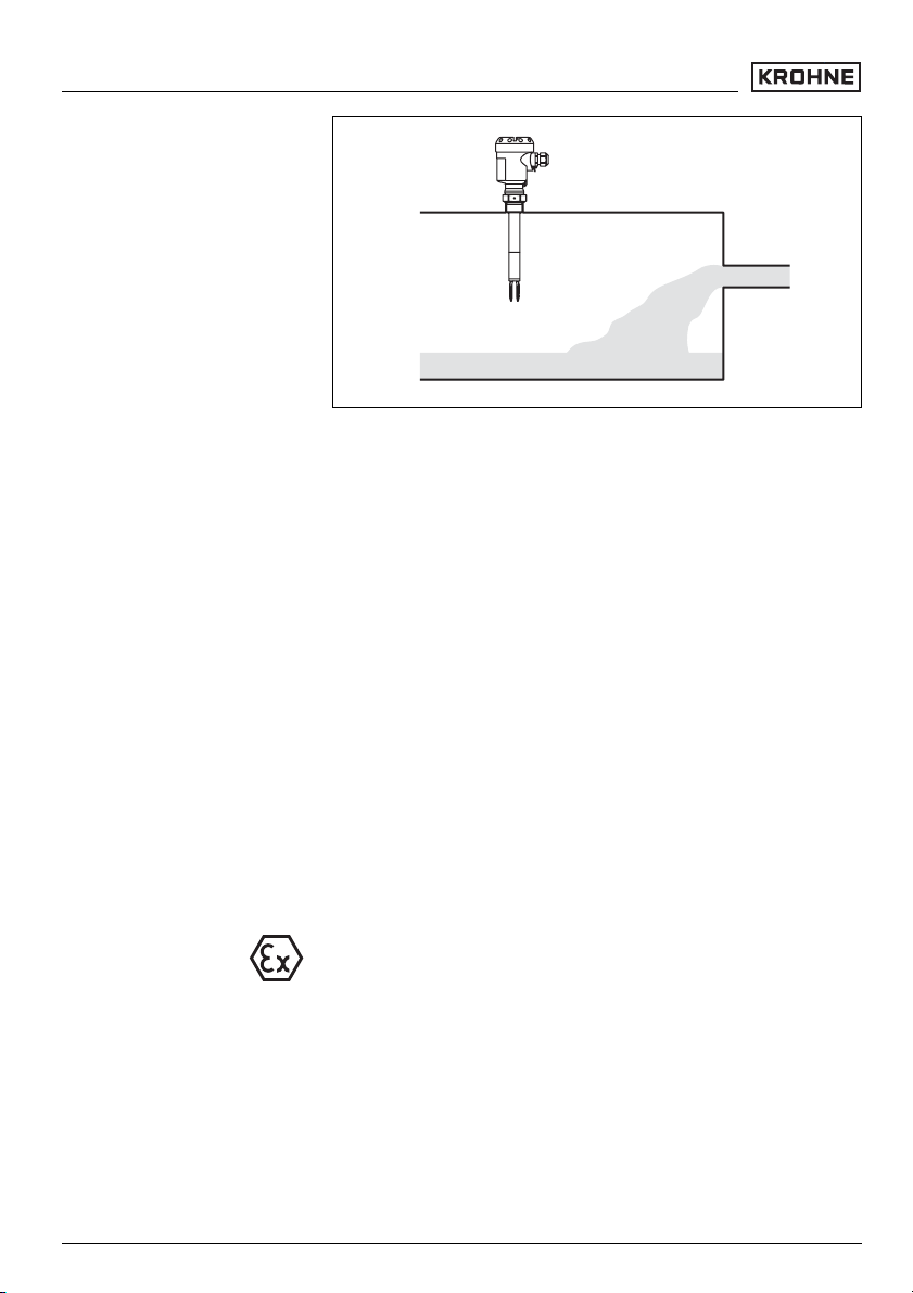
If OPTISWITCH 5200 C, 5250 C is mounted in the filling
stream, unwanted switching signals can be generated. Mount
OPTISWITCH 5200 C, 5250 C at a location in the vessel
where no disturbing influence from e.g. filling openings,
agitators, etc. can occur.
This applies particularly to instrument types with long extension tube.
30432-EN-050622
OPTISWITCH 5200 C, 5250 C - with transistor output 13
Mounting
Fig. 7: Inflowing medium
Flow
Agitators
If there is movement within the product, the tuning fork of
OPTISWITCH 5200 C, 5250 C should be mounted in such a
way that the surfaces of the fork are parallel to the product
movement.
Due to agitators, vibrations or similar, the level switch can be
subjected to strong lateral forces. For this reason, do not use
an overly long extension tube for OPTISWITCH 5200 C, 5250
C, but check if you can mount an OPTISWITCH 5100 C,
5150 C level switch on the side of the vessel in horizontal
position.
Extreme vibrations from the system side, e.g. by agitators or
turbulence in the vessel, e.g. by fluidization can cause the
extension tube of OPTISWITCH 5200 C, 5250 C to vibrate.
This will cause increased stress on the upper weld joint.
Should a longer tube version be necessary, you can provide a
suitable straining or fastening directly above the tuning fork to
fasten the extension tube.
This measure applies particularly to applications in Ex areas
category 1G or WHG. Make sure that the tube is not bent by
this measure.
30432-EN-050622
14 OPTISWITCH 5200 C, 5250 C - with transistor output
 Loading...