

Page 1
Technical Datasheet
Technical Datasheet
OPTISONIC 6300 P
OPTISONIC 6300 P
OPTISONIC 6300 POPTISONIC 6300 P
Technical DatasheetTechnical Datasheet
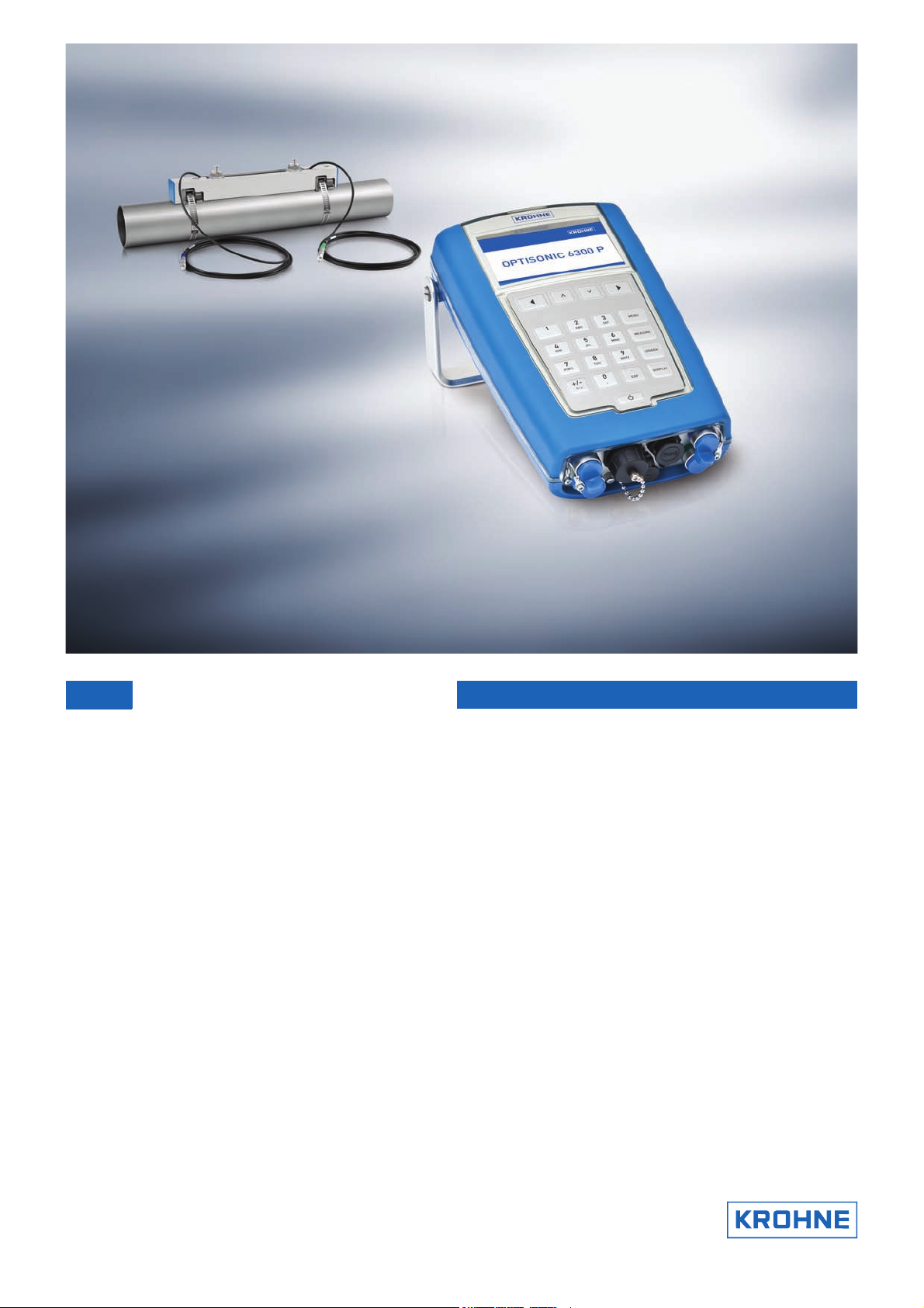
Portable ultrasonic clamp-on flowmeter
• User friendly operation through full colour graphic display and full keypad
• Quick and easy transfer of logged data to your PC through USB interface
• Sensors: robust, fast installation, high performance
© KROHNE 03/2013 - 4000950303 - TD OPTISONIC 6300 P R03 en
Page 2

CONTENTS
OPTISONIC 6300 P
1 Product features 3
1.1 Portable clamp-on flowmeter.......................................................................................... 3
1.2 Variants............................................................................................................................. 5
1.3 Measuring principle.......................................................................................................... 7
2 Technical data 8
2.1 Technical data................................................................................................................... 8
2.2 Dimensions and weights ................................................................................................ 14
2.2.1 Clamp-on sensor .................................................................................................................. 14
2.2.2 Converter............................................................................................................................... 15
2.2.3 I/O box ................................................................................................................................... 16
2.2.4 Trunk on wheels.................................................................................................................... 17
3 Installation 18
3.1 Intended use ................................................................................................................... 18
3.2 Find location and determine data .................................................................................. 18
4 Electrical connections 22
4.1 Safety instructions.......................................................................................................... 22
4.2 Power supply .................................................................................................................. 22
4.3 Signal cable .................................................................................................................... 23
4.4 Connection diagrams ..................................................................................................... 24
5 Application form 29
6 Notes 31
2
www.krohne.com 03/2013 - 4000950303 - TD OPTISONIC 6300 P R03 en
Page 3
OPTISONIC 6300 P
1.1 Portable clamp-on flowmeter
The new OPTISONIC 6300 P flowmeter combines mobile, straightforward and quick liquid
measurement with the proven precision and reliability of KROHNE ultrasonic technology. Simply
attach the sensor unit to the tube and connect the compact evaluation unit - now just read the
results. It is just as easy to use the device for data logging. Data is saved to a USB stick and
transferred to external evaluation systems. Its ease of use and flexibility make the
OPTISONIC 6300 P the ideal solution for flow measurement in a variety of applications in virtually
any sector of industry.
PRODUCT FEATURES 1
www.krohne.com03/2013 - 4000950303 - TD OPTISONIC 6300 P R03 en
3
Page 4

1 PRODUCT FEATURES
Highlights
• Quick and easy sensor mounting
• Comprehensive user interface
• Easy transfer of logged data to PC
• 14 hours battery life
• Energy measurement
Industries
• Chemicals
• Petrochemicals
• Power plants
• Water
• Oil & Gas
• Semi-conductor
• Food & Beverages
• Pharmaceuticals
• HVAC
• Metal & Steel
OPTISONIC 6300 P
Applications
• Commissioning of HVAC systems
• Checking of inline flowmeters
• Checking of pump performance
• Temporary replacement of defective flowmeters
• General flow related problem solving
4
www.krohne.com 03/2013 - 4000950303 - TD OPTISONIC 6300 P R03 en
Page 5
OPTISONIC 6300 P
1.2 Variants
The OPTISONIC 6300 P is a battery powered ultrasonic clamp-on flowmeter that can be fitted on
the outside of piping to measure the flow rate of liquids. The OPTISONIC 6300 P is intended for
temporary flow measurement. It consists of a combination of one or two clamp-on sensor(s) and
one handheld electronic signal converter.
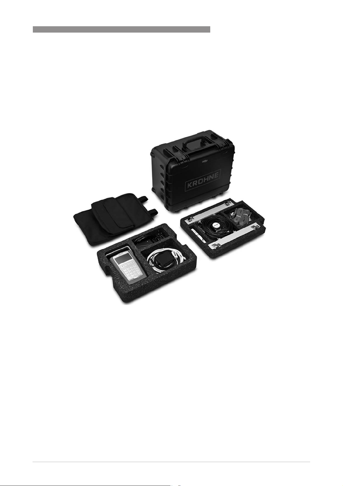
The OPTISONIC 6300 P comes as a complete and ready to use flowmeter in a robust case that
can be carried as a trolley.
PRODUCT FEATURES 1
What's standard included?
• UFC 300 P converter including battery
charger / power supply and mounting
strap
• Product documentation
• USB stick
• Coupling fat
• Tape measure
• Backpack
• Trunk on wheels
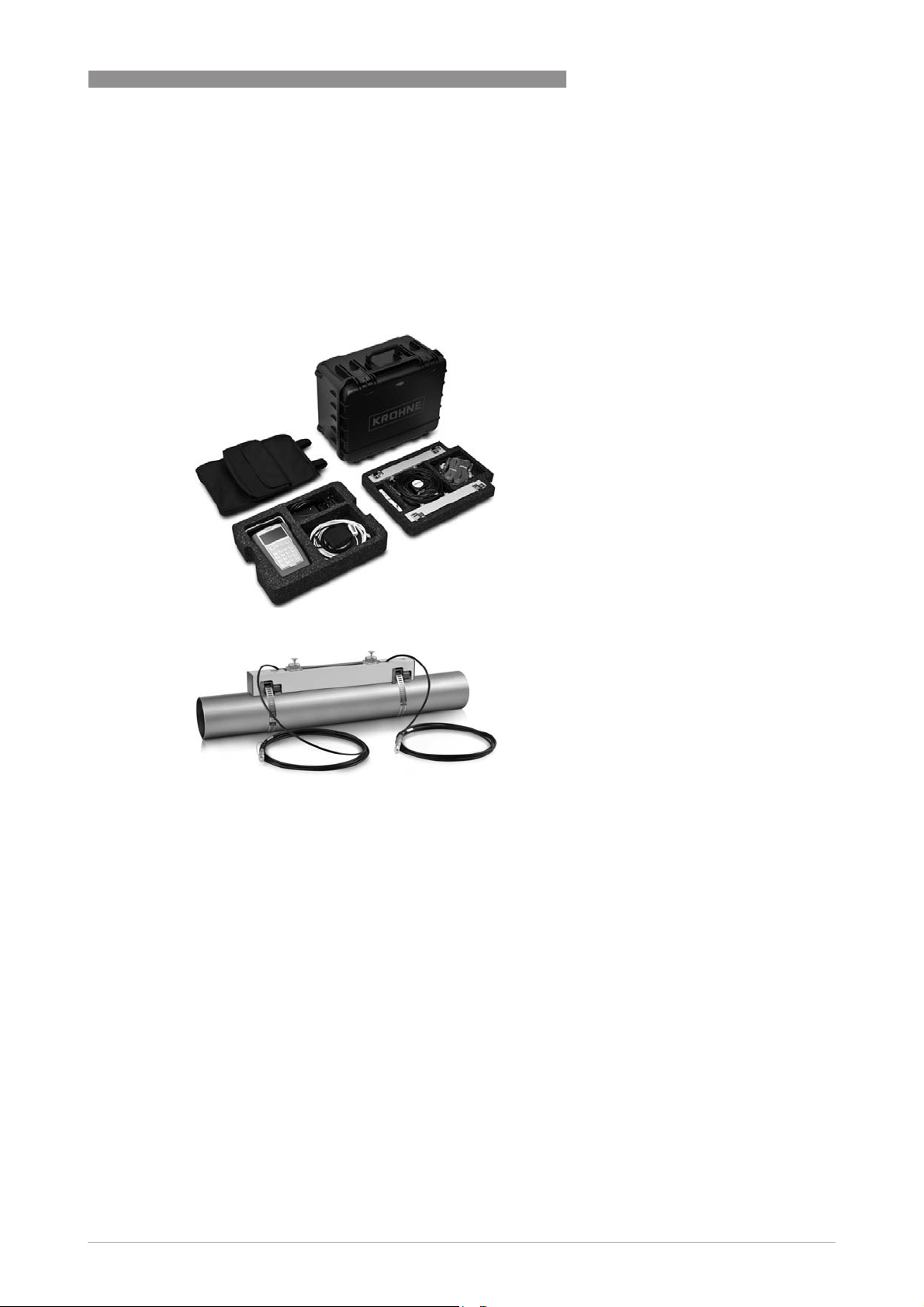
Flow sensor options
• Single rail flow sensor for pipe sizes
DN15...DN150 (½...6")
• Single rail flow sensor for pipe sizes
DN50...DN250 (2...10")
• Dual rail flow sensor for pipe sizes
DN200...DN1500 (8...60")
Two flow sensors of the same type can
be connected to the converter
electronics simultaneously for dual
path or dual pipe flow measurement.
A maximum of 4 sensor rails can be
fitted in the case.
www.krohne.com03/2013 - 4000950303 - TD OPTISONIC 6300 P R03 en
5
Page 6
1 PRODUCT FEATURES
OPTISONIC 6300 P
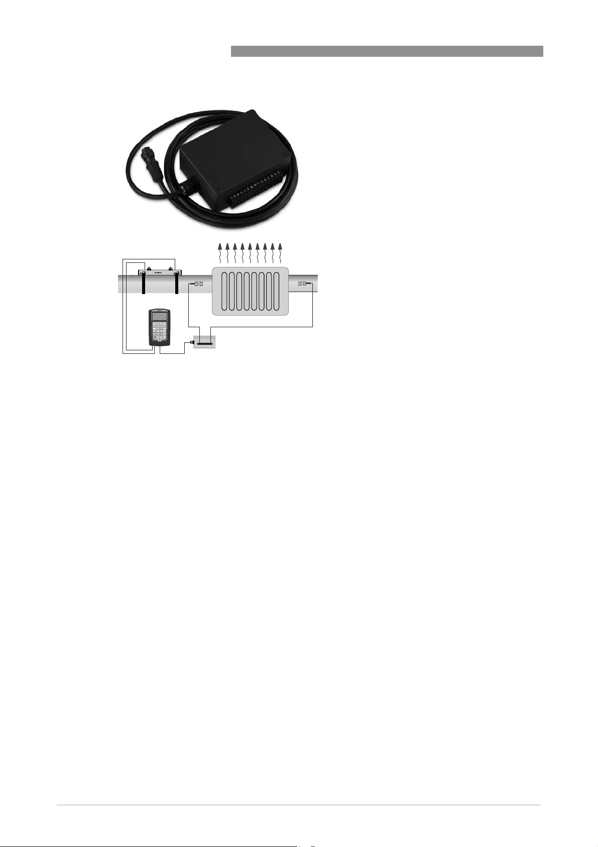
I/O connection
For connection of I/O signals like pulse or
current outputs a cable with I/O connection
box is available optionally.
Energy measurement
Standard the OPTISONIC 6300 P is provided
with a measurement option for thermal
energy. This requires the input of 2
temperature measurements in addtion to the
flow measurement.
For temperature measurement an I/O
connection box is available to connect
temperature transmitters. For direct
connection of PT100 sensors, the I/O box can
optionally be fitted with 2 temperature
transmitters. When temporary temperature
measurement is required 2 clamp-on PT100
sensors can be ordered optionally.
Optional thickness gauge
For setting up the flow measurement, the
pipewall thickness must be known. To
measure this, a pipewall thickness gauge can
be ordered with the OPTISONIC 6300 P.
6
www.krohne.com 03/2013 - 4000950303 - TD OPTISONIC 6300 P R03 en
Page 7
OPTISONIC 6300 P
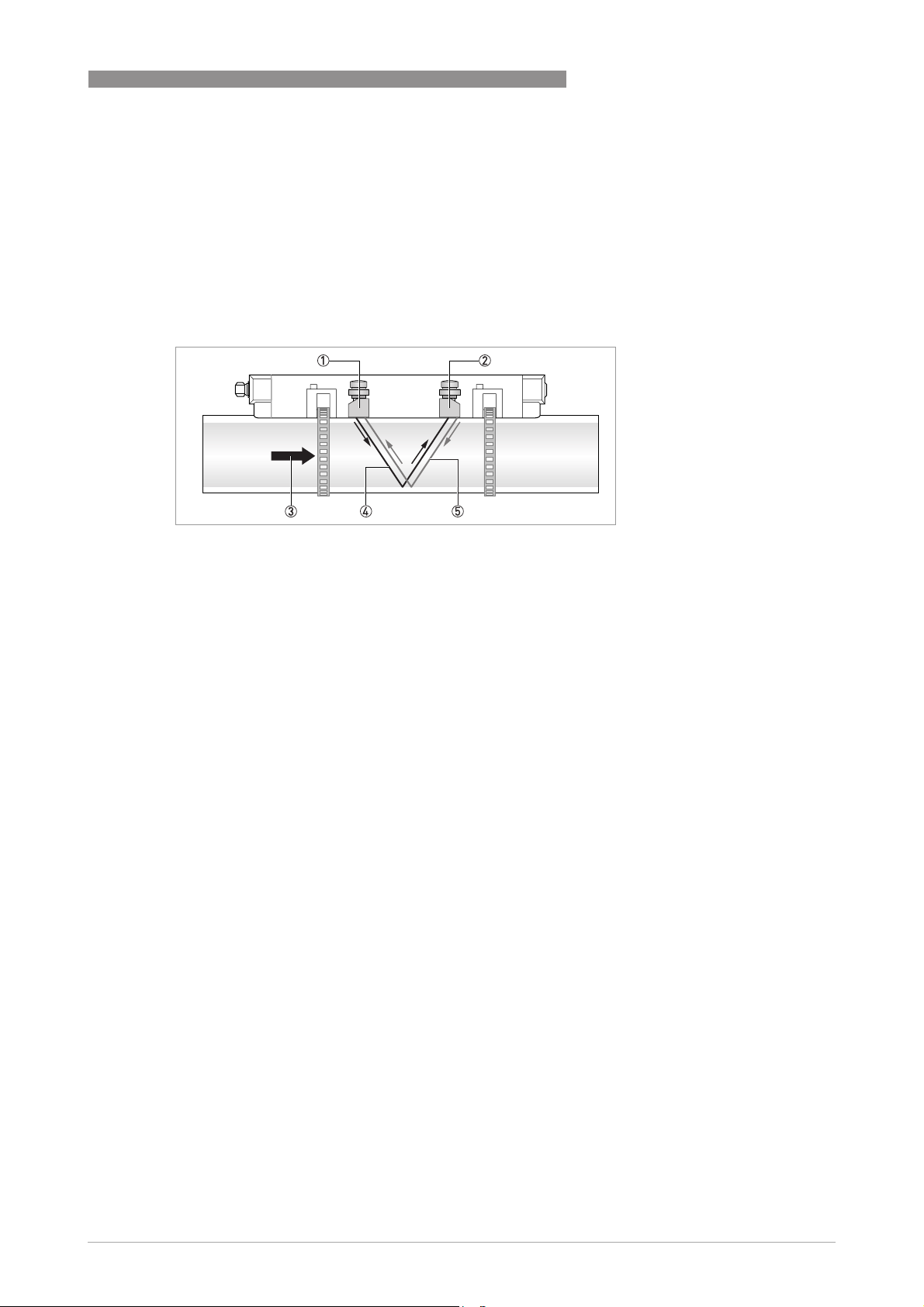
1.3 Measuring principle
• Like canoes crossing a river, acoustic signals are transmitted and received along a diagonal
measuring path.
• A sound wave going downstream with the flow travels faster than a sound wave going
upstream against the flow.
• The difference in transit time is directly proportional to the mean flow velocity of the medium.
PRODUCT FEATURES 1
Figure 1-1: Measuring principle
1 Transducer A
2 Transducer B
3 Flow velocity
4 Transit time from transducer A to B
5 Transit time from transducer B to A
www.krohne.com03/2013 - 4000950303 - TD OPTISONIC 6300 P R03 en
7
Page 8

2 TECHNICAL DATA
2.1 Technical data
•
The following data is provided for general applications. If you require data that is more
relevant to your specific application, please contact us or your local sales office.
•
Additional information (certificates, special tools, software,...) and complete product
documentation can be downloaded free of charge from the website (Download Center).
Measuring system
Measuring principle Ultrasonic transit time
Application range Flow measurement of liquids
Measured value
Measured value
Measured valueMeasured value
Primary measured value Transit time
Secondary measured value Volume flow, mass flow, flow speed, flow direction, speed of sound, gain,
Design
Signal converter
Signal converter
Signal converterSignal converter
Portable housing UFC 300 P
Measuring sensor
Measuring sensor
Measuring sensorMeasuring sensor
Standard Single or dual rail sensors with 1 or 2 MHz transducers
Optional OPTISONIC 6300 flow sensors using cable adapters
Diameter ranges
Diameter ranges
Diameter rangesDiameter ranges
DN15...150 / ½...6" One rail, 2 MHz transducers
DN50...250 / 2...10" One rail, 1 MHz transducers
DN200...1500 / 8...60" Two rails, 1 MHz transducers
Options
Options
OptionsOptions
Outputs 0(4)...20 mA, pulse, frequency and/or status output
Inputs 0(4)...20 mA (2x) with optional I/O box.
Counters 4 internal counters with a maximum of 8 counter places, for counting
USB 1x host port (PC can use OPTISONIC 6300 P as a removable media
Self diagnostics Integrated verification, diagnostic functions: flowmeter, process,
OPTISONIC 6300 P
signal to noise ratio, diagnosis value, reliability of flow measurement,
quality of acoustic signal, thermal energy (requires input of temperature
(2x)).
The measurement system consists of one or two measuring sensors and
a portable signal converter.
Outer diameter must be at least 20 mm / ¾".
volume, energy and/or mass units.
device)
1x slave (memory stick can be written by converter)
measured value, empty pipe detection, bar graph.
8
www.krohne.com 03/2013 - 4000950303 - TD OPTISONIC 6300 P R03 en
Page 9

OPTISONIC 6300 P
Display and user interface
Display and user interface
Display and user interfaceDisplay and user interface
Graphic display 4.3" TFT with LED backlight, daylight readable
Operator input elements 21 Key tactile keypad:
Display functions
Display functions
Display functionsDisplay functions
Menu Wizard for setup and configuration of measurements.
Thermal energy
measurement
Data logger Logging of selected measured / calculated values. Data to be logged and
Language of display texts English, French, German, Italian, Spanish.
Units Metric, British and US units selectable from list / free unit.
TECHNICAL DATA 2
272x480 dots resolution
The readability of the display could be reduced at ambient temperatures
below -25°C / -13°F.
1 on/off key
4 cursor keys for menu operation
12 keys for alpha / numerical input (SMS style)
4 function keys for direct access to main functions
Support for the configuration of 2 path / 2 pipe or 2 path / 1 pipe
measurement.
Averaging, adding or subtracting of measurement results of 2 path
measurements.
Storage of measurement configurations as site file.
Maximum of site files is 100.
Measurement data can be displayed as value or as bar or trend graph.
By input of 2 temperature sensors providing a temperature difference,
thermal energy can be calculated.
time interval can be set. A maximum number of 150000 values / 50 files
can be stored. Display of logged data through line graphs.
Other languages on request.
Measuring accuracy
Reference conditions Medium: water
Temperature: 20°C / 68°F
Straight inlet section: 10 DN
Maximum measuring error ±1% of the measured value for DN≥50 mm / 2" and v > 0.5 m/s / 1.5 ft/s
±3% of the measured value for DN<50 mm / 2" and v > 0.5 m/s / 1.5 ft/s
Repeatability <±0.2%
www.krohne.com03/2013 - 4000950303 - TD OPTISONIC 6300 P R03 en
9
Page 10

2 TECHNICAL DATA
Operating conditions
Temperature
Temperature
TemperatureTemperature
Process temperature Standard version: -40...+120°C / -40...+248°F
Ambient temperature Sensor: -40...+70°C / -40...+158°F
Storage temperature -30…+80°C / -22…+176°F
Pipe specifications
Pipe specifications
Pipe specificationsPipe specifications
Material Metal, plastic, ceramic, asbestos cement, internal / external coated
Pipewall thickness < 200 mm / 7.87"
Liner thickness < 20 mm / 0.79"
Media properties
Media properties
Media propertiesMedia properties
Physical condition Liquids
Viscosity < 100 cSt (general guideline)
Permissible gas content
(volume)
Permissible solid content
(volume)
Recommended flow velocity 0.5...20 m/s
OPTISONIC 6300 P
Signal converter: -20…+55°C / -4…+131°F
(Humidity: 5...80%, non condensing)
(Humidity: 5...80%, non condensing)
pipes (coatings and liners fully bonded to pipe wall)
For detailed information please contact your local representative.
≤ 2%
≤ 5%
Installation condititions
Measurement configuration Single pipe, single path
Single pipe, dual path
Dual pipe, dual path
Inlet run ≥ 10 DN straight length
Outlet run ≥ 5 DN straight length
Dimensions and weights For detailed information refer to
Dimensions and weights
on page 14.
Materials
Sensor Anodized aluminum (rail)
Converter Polyamide PA12, covered with TPE soft touch layer on the sides
Trunk on wheels Polypropylene
10
www.krohne.com 03/2013 - 4000950303 - TD OPTISONIC 6300 P R03 en
Page 11

OPTISONIC 6300 P
Electrical connections
Power supply Adapter for 100…240 VAC (-10% / +10%), 47...63 Hz
Signal cable double shielded, internal triax, length: 3 m / 15 ft
USB ports 1x for PC, 1x for memorystick
Inputs / outputs 15 pin connector for I/O interfacing with optional I/O box
TECHNICAL DATA 2
Adapter voltage: 13.2 V
Maximum power consumption: 10 W (25 W during charging)
Charging time: 8 hours
Battery type: Lithium polymer
Battery lifetime:
Battery lifetime:
Battery lifetime:Battery lifetime:
Measuring operation (display at 50% brightness): 14 hours
Optional: PT100 input:
Optional: PT100 input:
Optional: PT100 input:Optional: PT100 input:
Function: PT 100 temperature input by 2x KROHNE TT30C temperature
transmitters build into an I/O box
For specifications see TT30C datasheet.
Optional: temperature input:
Optional: temperature input:
Optional: temperature input:Optional: temperature input:
Function: temperature input by 2x KROHNE TSR-W 30 clamp-on
temperature sensors only in combination with I/O box with temperature
transmitters.
For specifications see TSR-W 30 datasheet.
Inputs and outputs
Connections Inputs and outputs can only be connected using the optional I/O box.
Description of used
abbreviations
Current output
Current output
Current outputCurrent output
Isolation The output is not galvanically isolated from the other circuits.
Output data All analog measurement parameters like volume and mass flow (at
Settings Q = 0%: 0…20 mA; Q = 100%: 10…21.5 mA
Operating data
Active U
Passive U
U
= external voltage
ext
= load + resistance
R
L
Uo = terminal voltage
= nominal current
I
nom
constant density), flow speed, speed of sound, gain, signal to noise ratio,
reliability of flow measurement, quality of acoustic signal, thermal
energy (requires input of temperature (2x)).
Error identification: 0…22 mA
= 15 VDC
int,nom
I ≤ 22 mA
RL ≤ 450 Ω
≤ 32 VDC
ext
I ≤ 22 mA
≥ 1.8 V at I = 22 mA
U
0
www.krohne.com03/2013 - 4000950303 - TD OPTISONIC 6300 P R03 en
11
Page 12

2 TECHNICAL DATA
Pulse or frequency output
Pulse or frequency output
Pulse or frequency outputPulse or frequency output
Isolation The output is galvanically isolated from the other circuits.
Output data For pulse counting and/or analog output: Volume flow, mass flow,
Function Can be set as a pulse output or frequency output
Settings For Q = 100%: 0.01...10000 pulses per second or pulses per unit volume
Operating data
Active U
Passive U
OPTISONIC 6300 P
thermal energy (requires input of temperature (2x)
As analog output: Flow speed, speed of sound, gain, signal to noise ratio,
reliability of flow measurement, quality of acoustic signal
Pulse width: setting automatic, symmetric or fixed (0.05...2000 ms)
= 15 VDC
nom
ffff
≤ 100 Hz:
100 Hz:
100 Hz: 100 Hz:
max
max
maxmax
I ≤ 20 mA
open:
I ≤ 0.05 mA
closed:
= 15 V at I = 20 mA
U
0,nom
100 Hz < f
100 Hz < f
100 Hz < f100 Hz < f
I ≤ 20 mA
open:
I ≤ 0.05 mA
closed:
U
0,nom
U
0,nom
U
0,nom
≤ 32 VDC
ext
ffff
≤ 100 Hz:
max
max
maxmax
I ≤ 100 mA
open:
I ≤ 0.05 mA at U
closed:
U
0, max
U
0, max
100 Hz < f
100 Hz < f
100 Hz < f100 Hz < f
I ≤ 20 mA
open:
I ≤ 0.05 mA at U
closed:
U
0, max
U
0, max
U
0, max
≤ 10 kHz:
10 kHz:
10 kHz: 10 kHz:
max
max
maxmax
= 13.5V at I=1mA
= 12.5 V at I = 10 mA
= 9 V at I = 20 mA
100 Hz:
100 Hz: 100 Hz:
= 32 VDC
ext
= 0.2 V at I ≤ 10 mA
= 2 V at I ≤ 100 mA
≤ 10 kHz:
10 kHz:
10 kHz: 10 kHz:
max
max
maxmax
=32VDC
ext
= 1.5 V at I ≤ 1mA
= 2.5 V at I ≤ 10 mA
= 5.0 V at I ≤ 20 mA
12
www.krohne.com 03/2013 - 4000950303 - TD OPTISONIC 6300 P R03 en
Page 13

OPTISONIC 6300 P
Status output
Status output
Status outputStatus output
Isolation The output is galvanically isolated from the other circuits.
Function and settings Settable as automatic measuring range change, indicator for direction of
Operating data
Active U
Passive U
Current inputs
Current inputs
Current inputsCurrent inputs
Isolation The inputs are not galvanically isolated from the other circuits.
Function Input of temperature, used for energy calculation in combination with
Operating data
Active U
Passive U
TECHNICAL DATA 2
flow, overflow, error, operating point or empty pipe detection
Status and/or control: ON or OFF
= 15 VDC
int
I ≤ 20 mA
open:
I ≤ 0.05 mA
closed:
= 15 V at I = 20 mA
U
0, nom
≤ 32 VDC
ext
I ≤ 100 mA
open:
I ≤ 0.05 mA at U
closed:
= 0.2 V at I ≤ 10 mA
U
0, max
U
= 2 V at I ≤ 100 mA
0, max
flow measurement
Range: -50...500°C / -58...932°F (default: 0...120°C / -32...248°F)
= 15 VDC
int
I ≤ 22 mA
= 26 mA (electronically limited)
I
max
U
= 9 V with I ≤ 22 mA
0, min
≤ 32 VDC
ext
®
No HART
I ≤ 22 mA
= 26 mA (electronically limited)
I
max
U
= 5 V with I ≤ 22 mA
0, max
No HART
®
=32VDC
ext
Approvals and certificates
CE
CE
CECE
This device fulfills the statutory requirements of the EC directives.
The manufacturer certifies successful testing of the product by applying
the CE mark.
Electromagnetic compatibility Directive: 2004/108/EC
Harmonized standard: EN 61326-1: 2006
Low voltage directive Directive: 2006/95/EC
Harmonized standard: EN 61010: 2001
Other approvals and standards
Other approvals and standards
Other approvals and standardsOther approvals and standards
Protection category acc. to
IEC 529 / EN 60529 /
NEMA 250/2003
Shock test sensor IEC 60068-2-27
Vibration test sensor IEC 60068-2-64
Sensor: IP 67 / NEMA 6
Converter: IP 65 / NEMA 4
Trunk on wheels: IP 67 / NEMA 6
Power adapter: IP 40 / NEMA 1
www.krohne.com03/2013 - 4000950303 - TD OPTISONIC 6300 P R03 en
13
Page 14

2 TECHNICAL DATA
2.2 Dimensions and weights
2.2.1 Clamp-on sensor
Dimensions [mm] Approx. weight
L H W
OPTISONIC 6300 P
[kg]
406 76 39.2 2.1 1
1 with transducers / cable, without mounting strap
Dimensions [inches] Approx. weight
[lb]
L H W
16.0 3.0 2.5 4.6 1
1 with transducers / cable, without mounting strap
14
www.krohne.com 03/2013 - 4000950303 - TD OPTISONIC 6300 P R03 en
Page 15

OPTISONIC 6300 P
2.2.2 Converter
TECHNICAL DATA 2
123
456
GHI JKL MNO
789
PQRS TUV WXYZ
+/- 0
A/a
ABC DEF
-
I/O
DISPLAY
LOGGER
EXP
MENU
Dimensions UFC 300 P converter
Dimensions [mm] Approx. weight
a b c d
247 289 168 66 1.6
Dimensions [inch] Approx. weight
a b c d
9.7 11.4 6.6 2.6 3.5
[kg]
[lb]
www.krohne.com03/2013 - 4000950303 - TD OPTISONIC 6300 P R03 en
15
Page 16

2 TECHNICAL DATA
2.2.3 I/O box
OPTISONIC 6300 P
a
b
b
c
Dimensions I/O box
Dimensions [mm] Approx. weight [kg]
a b c
112.5 84.6 41.3 0.2
Dimensions [inch] Approx. weight [lb]
a b c
4.4 3.3 1.6 0.44
16
www.krohne.com 03/2013 - 4000950303 - TD OPTISONIC 6300 P R03 en
Page 17

OPTISONIC 6300 P
2.2.4 Trunk on wheels
Dimensions trunk on wheels
Dimensions [mm] Approx. weight [kg]
a b c
TECHNICAL DATA 2
565 374 241 6.2
Dimensions [inch] Approx. weight [lb]
a b c
22.2 14.7 9.5 13.7
www.krohne.com03/2013 - 4000950303 - TD OPTISONIC 6300 P R03 en
17
Page 18

3 INSTALLATION
3.1 Intended use
Responsibility for the use of the measuring devices with regard to suitability, intended use and
corrosion resistance of the used materials against the measured fluid lies solely with the
operator.
The manufacturer is not liable for any damage resulting from improper use or use for other than
the intended purpose.
The OPTISONIC 6300 P
OPTISONIC 6300 P portable clamp-on flow meter is designed for measurement of liquid
OPTISONIC 6300 POPTISONIC 6300 P
flows in full pipes, datalogging and transfer of logged results to the PC. The portable clamp-on
flow meter makes it possible to measure the flow on places temporary or you can make use of it
if you want to compare the output with other measurement devices.
If an inline measurement device is broken and you are in need of the information the OPTISONIC
6300 P might be the solution for you.
3.2 Find location and determine data
Inlet, outlet and recommended mounting area
To perform an accurate flow measurement preferably mount the sensor rail at least 10 DN
downstream of a flow disturbance like elbows, valves, headers or pumps. Follow the given
installation recommendations.
OPTISONIC 6300 P
18
Figure 3-1: Inlet, outlet and recommended mounting area
1 Min. 10 DN
2 Min. 5 DN
3 Recommended installation location (120°)
Make sure that the rail is not mounted at the highest point (risk for air bubbles) or at the lowest
point (risk for particles) of the pipe.
www.krohne.com 03/2013 - 4000950303 - TD OPTISONIC 6300 P R03 en
Page 19

OPTISONIC 6300 P
Long horizontal pipes
• Install on slightly ascending pipe section.
• If not possible, make sure that the flow velocity is high enough to prevent air, gas or vapor to
collect in upper part.
• In partially filled pipes, the clamp-on flowmeter will report incorrect flow rates, or not
measure.
Figure 3-2: Long horizontal pipes
Vertical pipelines
INSTALLATION 3
Make sure that the pipe is fully filled at all times.
Both ascending and descending flow directions are measurable.
Figure 3-3: Mounting on vertical pipelines is possible
www.krohne.com03/2013 - 4000950303 - TD OPTISONIC 6300 P R03 en
19
Page 20

3 INSTALLATION
Open feed or discharge
Install meter on a lowered section of the pipe to make sure that there is a full pipe condition.
Figure 3-4: Open feed or discharge
Down going pipeline over 5 m / 16 ft length
Install an air vent downstream of the flowmeter to prevent vacuum. It may cause gases to come
out of solution (cavitate) that prevent a proper measurement.
OPTISONIC 6300 P
Figure 3-5: Down going pipeline over 5 m / 16 ft length
Position of control valve
Always install control valves downstream of the flowmeter in order to avoid cavitation or
distortion of the flow profile.
Figure 3-6: Position of control valve
20
www.krohne.com 03/2013 - 4000950303 - TD OPTISONIC 6300 P R03 en
Page 21

OPTISONIC 6300 P
Position of pump
Never install the flowmeter at the suction side of a pump in order to avoid cavitation or flashing
in the flowmeter.
Figure 3-7: Position of pump
Determine data and dimensions of pipe
The next data must be available before proceeding.
• Use the supplied tape measure to determine the outside diameter of the pipe.
• Determine the pipe wall thickness. A pipe wall thickness gauge or pipe tables can be used for
this.
• Find out what the material of the pipe is.
• If the pipe has a liner, find out the liner material and the thickness of the liner.
INSTALLATION 3
www.krohne.com03/2013 - 4000950303 - TD OPTISONIC 6300 P R03 en
21
Page 22

4 ELECTRICAL CONNECTIONS
4.1 Safety instructions
All work on the electrical connections may only be carried out with the power disconnected. Take
note of the voltage data on the nameplate!
Observe the national regulations for electrical installations!
Observe without fail the local occupational health and safety regulations. Any work done on the
electrical components of the measuring device may only be carried out by properly trained
specialists.
Look at the device nameplate to ensure that the device is delivered according to your order.
Check for the correct supply voltage printed on the nameplate.
4.2 Power supply
Only use the supplied AC charger to charge the battery of the converter!
OPTISONIC 6300 P
USB
i/o
12
DC in
1
Plug in the connector of the supplied charger at the connector 1. Then insert the main power
connector into your mains outlet.
The battery status indicator will be accurate after an initial full discharge directly followed by a
full charge of the battery.
22
www.krohne.com 03/2013 - 4000950303 - TD OPTISONIC 6300 P R03 en
Page 23

OPTISONIC 6300 P
4.3 Signal cable
Find the calibration numbers that are noted on the labels on the cable of each transducer. Make
sure that both transducers have the same calibration number as shown by the converter.
The signal cables are prefixed to the transducers in the factory.
ELECTRICAL CONNECTIONS 4
1
2
1
2
1
123
456
GHI JKL MNO
789
PQRS TUV WXYZ
+/- 0
A/a
I/O
DEF
ABC
DISPLAY
LOGGER
EXP
MENU
-
2
Figure 4-1: Connecting signal cables
1 Connector for "UP" transducer (blue)
2 Connector for "DOWN" transducer (green)
You can measure two paths with this converter simultaneously. Use the left pair of connectors
for path 1 and the right pair for path 2.
www.krohne.com03/2013 - 4000950303 - TD OPTISONIC 6300 P R03 en
23
Page 24

4 ELECTRICAL CONNECTIONS
4.4 Connection diagrams
mA meter
0...20 mA or 4...20 mA and other
RL is the internal resistance of the measuring point including the cable
resistance
DC voltage source (U
OPTISONIC 6300 P
), external power supply, any connection polarity
ext
DC voltage source (U
connection diagrams
Internal DC voltage source
Controlled internal power source in the device
Electronic or electromagnetic counter
At frequencies above 100 Hz, shielded cables must be used to connect the
counters.
Ri Internal resistance of the counter
Button, NO contact or similar
), observe connection polarity according to
ext
24
www.krohne.com 03/2013 - 4000950303 - TD OPTISONIC 6300 P R03 en
Page 25

OPTISONIC 6300 P
Observe connection polarity.
4...20 mA current output active
• U
int,nom
• I ≤ 22 mA
• R
L
• Not galvanically isolated.
ELECTRICAL CONNECTIONS 4
= 15 VDC nominal
≤ 600 Ω
Figure 4-2: Current output active I
a
Current output passive, basic I/Os
• U
• I ≤ 22 mA
• U
• R
• Not galvanically isolated.
Figure 4-3: Current output passive I
≤ 32 VDC
ext
≥ 1.8 V
0
≤ (U
L
ext-U0
)/I
max
p
www.krohne.com03/2013 - 4000950303 - TD OPTISONIC 6300 P R03 en
25
Page 26

4 ELECTRICAL CONNECTIONS
Pulse / frequency output
•
Any connection polarity.
•
Galvanically isolated.
Pulse/frequency output passive
• U
• f
• f
• If the following maximum load resistance R
• The minimum load resistance R
• Can also be set as a status output; for the electrical connection, see status output connection
≤ 32 VDC
ext
in operating menu set to f
max
max
I ≤ 100 mA
open:
I ≤ 0.05 mA at U
= 32 VDC
ext
closed:
U
U
= 0.2 V at I ≤ 10 mA
0, max
= 2 V at I ≤ 100 mA
0, max
in the operating menu set to 100 Hz < f
max
I ≤ 20 mA
open:
I ≤ 0.05 mA at U
= 32 VDC
ext
closed:
U
U
U
= 1.5 V at I ≤ 1 mA
0, max
= 2.5 V at I ≤ 10 mA
0, max
= 5.0 V at I ≤ 20 mA
0, max
reduced accordingly by parallel connection of R:
f ≤ 100 Hz: R
f ≤ 1 kHz: R
f ≤ 10 kHz: R
R
L, min
=(U
ext-U0
L, max
L, max
L, max
= 47 kΩ
= 10 kΩ
= 1 kΩ
)/I
max
L, min
diagram.
≤ 100 Hz:
≤ 10 kHz:
max
is exceeded, the load resistance RL must be
L, max
is calculated as follows:
OPTISONIC 6300 P
26
Pulse/frequency output active
• U
• f
• f
= 15 VDC
nom
in operating menu set to f
max
I ≤ 20 mA
open:
I ≤ 0.05 mA
closed:
U
= 15 V at I = 20 mA
0, nom
in the operating menu set to 100 Hz < f
max
I ≤ 20 mA
open:
I ≤ 0.05 mA
closed:
U
U
U
= 13.5 V at I ≤ 1 mA
0, nom
= 12.5 V at I ≤ 10 mA
0, nom
= 9.0 V at I ≤ 20 mA
0, nom
≤ 100 Hz:
max
≤ 10 kHz:
max
www.krohne.com 03/2013 - 4000950303 - TD OPTISONIC 6300 P R03 en
Page 27

OPTISONIC 6300 P
ELECTRICAL CONNECTIONS 4
• If the following maximum load resistance R
reduced accordingly by parallel connection of R:
f ≤ 100 Hz: R
f ≤ 1 kHz: R
f ≤ 10 kHz: R
• The minimum load resistance R
L, min
=(U
ext-U0
R
L, max
L, max
L, max
= 47 kΩ
= 10 kΩ
= 1 kΩ
)/I
max
is calculated as follows:
L, min
C+
C-
D
D-
is exceeded, the load resistance RL must be
L, max
Figure 4-4: Pulse frequency output active P
•
Any connection polarity.
•
Galvanically isolated.
a
Status output
• U
• I ≤ 100 mA
• R
• open:
• The output is open when the device is de-energized.
≤ 32 VDC
ext
= 47 kΩ
L, max
L, min
=(U
ext-U0
R
I ≤ 0.05 mA at U
closed:
U
U
= 0.2 V at I ≤ 10 mA
0, max
= 2 V at I ≤ 100 mA
0, max
)/I
= 32 VDC
ext
max
Figure 4-5: Status output / limit switch passive S
www.krohne.com03/2013 - 4000950303 - TD OPTISONIC 6300 P R03 en
p
27
Page 28

4 ELECTRICAL CONNECTIONS
Current input active
• U
• I ≤ 22 mA
• I
max
• U
• no
no HART
nono
• Not galvanically isolated
• X designates the connection terminals A or B, depending on the version of the signal
converter.
= 15 VDC
int, nom
≤ 26 mA (electronically limited)
= 19 V at I ≤ 22 mA
0, min
®
OPTISONIC 6300 P
Figure 4-6: Current input active IIn
1 Signal
2 2-wire transmitter (e.g. temperature)
a
28
www.krohne.com 03/2013 - 4000950303 - TD OPTISONIC 6300 P R03 en
Page 29

OPTISONIC 6300 P
Please fill in this form and fax or email it to your local representive. Please include a sketch of
the pipe layout as well, including the X, Y, Z dimensions.
Customer information
Date
Submitted by
Company
Address
Telephone
Fax
E-mail
Flow application data
Reference information (name, tag etc)
New application
Existing application, currently using:
Measurement objective:
Fluid:
Flowrate
Flowrate
FlowrateFlowrate
Normal:
Minimum:
Maximum:
Temperature
Temperature
TemperatureTemperature
Normal:
Minimum:
Maximum:
Viscosity
Viscosity
ViscosityViscosity
Normal:
Maximum:
Continuous / pulsating flow. Description:
Entrained air percentage (volume):
Eintrained solids percentage (volume):
Emulsion present (e.g. oil / water):
Emulsion percentage product A:
Emulsion percentage product B:
APPLICATION FORM 5
www.krohne.com03/2013 - 4000950303 - TD OPTISONIC 6300 P R03 en
29
Page 30

5 APPLICATION FORM
Piping details
Nominal pipe size:
Outer diameter:
Wall thickness / schedule:
Pipe material:
Pipe condition (old / new / painted /
internal scaling / exterior rust):
Liner material:
Liner thickness:
Straight inlet / outlet section (DN):
Upstream situation (elbows, valves,
pumps):
Flow orientation (vertical up / horizontal
/ vertical down / other):
Environment details
Corrosive atmosphere:
Sea water:
High humidity (% R.H.)
Nucleair (radiation):
Hazardous area:
Additional details:
OPTISONIC 6300 P
Hardware requirements:
Accuracy requested (percentage of
rate):
Power supply (voltage, AC / DC):
Analog output (4-20 mA)
Pulse (specify minimum pulse width,
pulse value):
Digital protocol:
Options:
Remote mounted signal converter:
specify cable length:
Accessories
30
www.krohne.com 03/2013 - 4000950303 - TD OPTISONIC 6300 P R03 en
Page 31

OPTISONIC 6300 P
NOTES 6
www.krohne.com03/2013 - 4000950303 - TD OPTISONIC 6300 P R03 en
31
Page 32

K
K
K
KROHNE product overview
• Electromagnetic flowmeters
• Variable area flowmeters
• Ultrasonic flowmeters
• Mass flowmeters
• Vortex flowmeters
• Flow controllers
• Level meters
• Temperature meters
• Pressure meters
• Analysis products
• Products and systems for the oil & gas industry
• Measuring systems for the marine industry
Head Office KROHNE Messtechnik GmbH
Ludwig-Krohne-Str. 5
47058 Duisburg (Germany)
Tel.:+49 (0)203 301 0
Fax:+49 (0)203 301 10389
info@krohne.de
The current list of all KROHNE contacts and addresses can be found at:
© KROHNE 03/2013 - 4000950303 - TD OPTISONIC 6300 P R03 en - Subject to change without notice.
www.krohne.com
 Loading...