

Page 1
Quick Start
Quick Start
OPTISONIC 3400
OPTISONIC 3400
OPTISONIC 3400OPTISONIC 3400
Quick StartQuick Start
Multi purpose, all-round, ultrasonic flowmeter for
liquids in all industrial processes
ER 2.2.7_
© KROHNE 02/2015 - QS OPTISONIC 3400 - 4002741204-R04 en
Page 2

CONTENTS
OPTISONIC 3400
1 Safety instructions 4
2 Installation 5
2.1 Scope of delivery............................................................................................................... 5
2.2 Device description ............................................................................................................ 6
2.3 Nameplates ...................................................................................................................... 7
2.3.1 Example of nameplate for the compact version .................................................................... 7
2.3.2 Nameplate for the measuring sensor (field version)............................................................. 8
2.3.3 Examples of nameplates on the signal converter (field version) .......................................... 8
2.4 Storage ........................................................................................................................... 10
2.5 Transport ........................................................................................................................ 10
2.6 Pre-installation requirements ....................................................................................... 11
2.7 General requirements .................................................................................................... 11
2.7.1 Vibration ................................................................................................................................ 11
2.8 Installation conditions ....................................................................................................12
2.8.1 Inlet and outlet...................................................................................................................... 12
2.8.2 Bends in 2 or 3 dimensions................................................................................................... 12
2.8.3 T-section ............................................................................................................................... 12
2.9 Bends .............................................................................................................................. 13
2.10 Open feed or discharge ................................................................................................ 13
2.11 Position of pump........................................................................................................... 14
2.12 Control valve ................................................................................................................. 14
2.13 Down going pipeline over 5 m /16 ft length ................................................................. 15
2.14 Insulation ...................................................................................................................... 15
2.15 Mounting ....................................................................................................................... 16
2.16 Flange deviation............................................................................................................ 16
2.17 Mounting position .........................................................................................................16
2.18 Mounting the field housing, remote version ................................................................ 17
2.18.1 Pipe mounting ..................................................................................................................... 17
2.18.2 Turning the display of the field housing version ................................................................ 18
3 Electrical connections 19
3.1 Safety instructions.......................................................................................................... 19
3.2 Signal cable (remote versions only)............................................................................... 19
3.3 Power supply .................................................................................................................. 21
3.4 Laying electrical cables correctly .................................................................................. 22
3.5 Inputs and outputs, overview ......................................................................................... 23
3.5.1 Combinations of the inputs/outputs (I/Os) ........................................................................... 23
3.5.2 Description of the CG number .............................................................................................. 24
3.5.3 Fixed, non-alterable input/output versions.......................................................................... 25
3.5.4 Alterable input/output versions............................................................................................ 26
4 Technical data 27
4.1 Dimensions and weights ................................................................................................ 27
4.2 Variants........................................................................................................................... 27
4.3 Standard flow sensor ..................................................................................................... 28
4.4 Variant flow sensor; XXT - High Viscosity and Cryogenic (SS) versions........................ 34
2
www.krohne.com 02/2015 - QS OPTISONIC 3400 - 4002741204-R04 en
Page 3

OPTISONIC 3400
CONTENTS
4.5 Signal converter housing ............................................................................................... 40
5 Notes 41
www.krohne.com02/2015 - QS OPTISONIC 3400 - 4002741204-R04 en
3
Page 4
1
SAFETY INSTRUCTIONS
Warnings and symbols used
DANGER!
This information refers to the immediate danger when working with electricity.
DANGER!
These warnings must be observed without fail. Even partial disregard of this warning can lead to
serious health problems and even death. There is also the risk of seriously damaging the device
or parts of the operator's plant.
WARNING!
Disregarding this safety warning, even if only in part, poses the risk of serious health problems.
There is also the risk of damaging the device or parts of the operator's plant.
CAUTION!
Disregarding these instructions can result in damage to the device or to parts of the operator's
plant.
INFORMATION!
These instructions contain important information for the handling of the device.
OPTISONIC 3400
HANDLING
• This symbol designates all instructions for actions to be carried out by the operator in the
specified sequence.
i RESULT
RESULT
RESULTRESULT
This symbol refers to all important consequences of the previous actions.
Safety instructions for the operator
CAUTION!
Installation, assembly, start-up and maintenance may only be performed by appropriately
trained personnel. The regional occupational health and safety directives must always be
observed.
LEGAL NOTICE!
The responsibility as to the suitability and intended use of this device rests solely with the user.
The supplier assumes no responsibility in the event of improper use by the customer. Improper
installation and operation may lead to loss of warranty. In addition, the "Terms and Conditions of
Sale" apply which form the basis of the purchase contract.
INFORMATION!
•
Further information can be found on the supplied CD-ROM in the manual, on the data sheet,
in special manuals, certificates and on the manufacturer's website.
•
If you need to return the device to the manufacturer or supplier, please fill out the form
contained on the CD-ROM and send it with the device. Unfortunately, the manufacturer
cannot repair or inspect the device without the completed form.
4
www.krohne.com 02/2015 - QS OPTISONIC 3400 - 4002741204-R04 en
Page 5
OPTISONIC 3400
2.1 Scope of delivery
INFORMATION!
Do a check of the packing list to make sure that you have all the elements given in the order.
INFORMATION!
Inspect the packaging carefully for damages or signs of rough handling. Report damage to the
carrier and to the local office of the manufacturer.
INFORMATION!
The field device will arrive in two cartons. One carton contains the converter and one carton
contains the sensor.
INFORMATION!
Make sure to combine the sensor and the converter correctly, so they match by the devices
serial number.
INSTALLATION
2
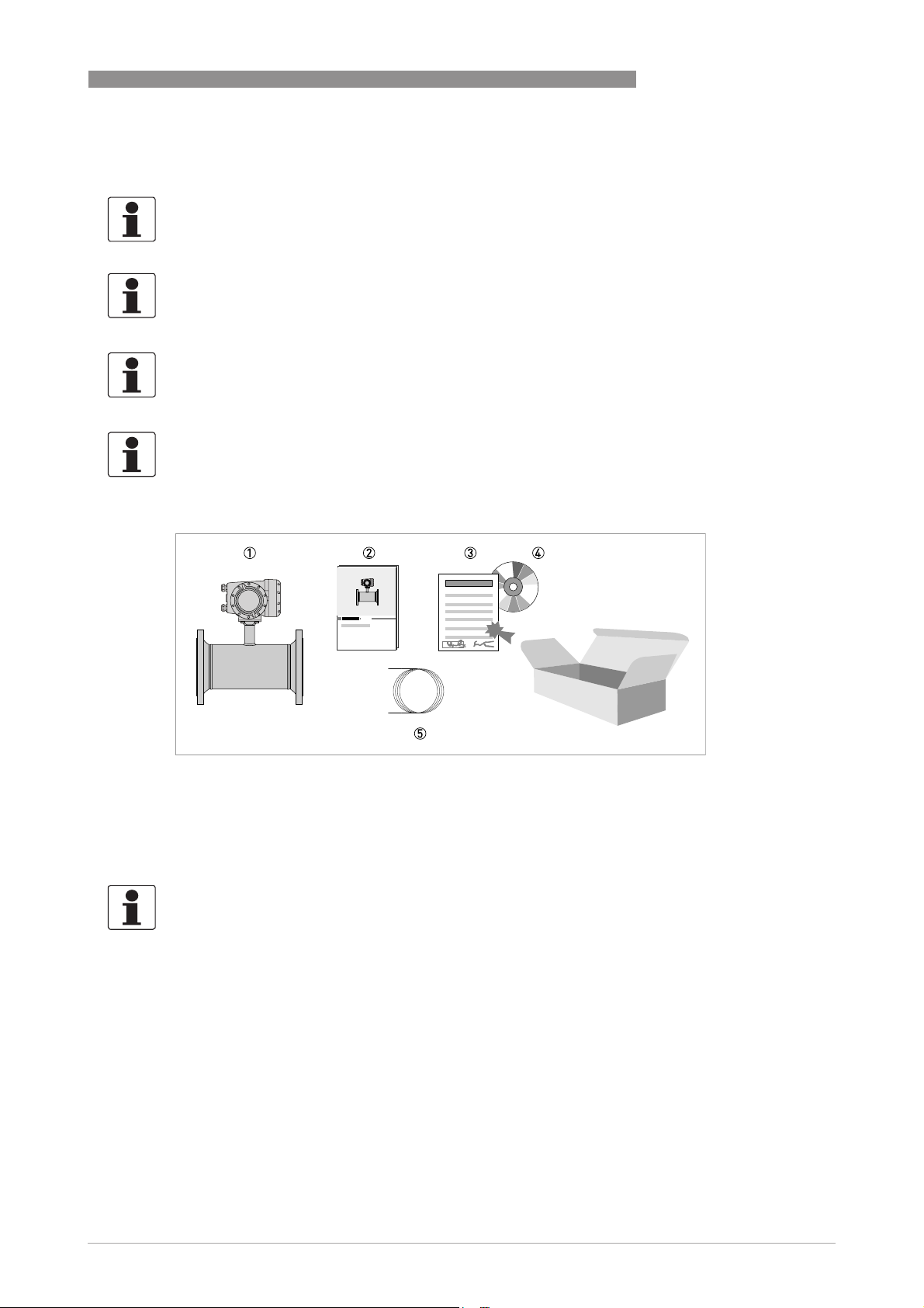
Figure 2-1: Scope of delivery - compact version
1 Ordered flowmeter
2 Product documentation
3 Factory calibration certificate
4 CD-ROM with product documentation in available languages
5 Signal cable (remote versions only)
INFORMATION!
Assembly materials and tools are not part of the delivery. Use the assembly materials and tools
in compliance with the applicable occupational health and safety directives.
www.krohne.com02/2015 - QS OPTISONIC 3400 - 4002741204-R04 en
5
Page 6
2
INSTALLATION
2.2 Device description
This ultrasonic flowmeter is designed for the continuous measurement of actual volume flow,
mass flow, flow speed, velocity of sound, gain, SNR and diagnosis value.
Exclusively for measuring conductive and / or non-conductive fluids in closed, completely filled
pipeline circuits.
Your measuring device is supplied ready for operation. The factory settings for the operating
data have been made in accordance with your order specifications.
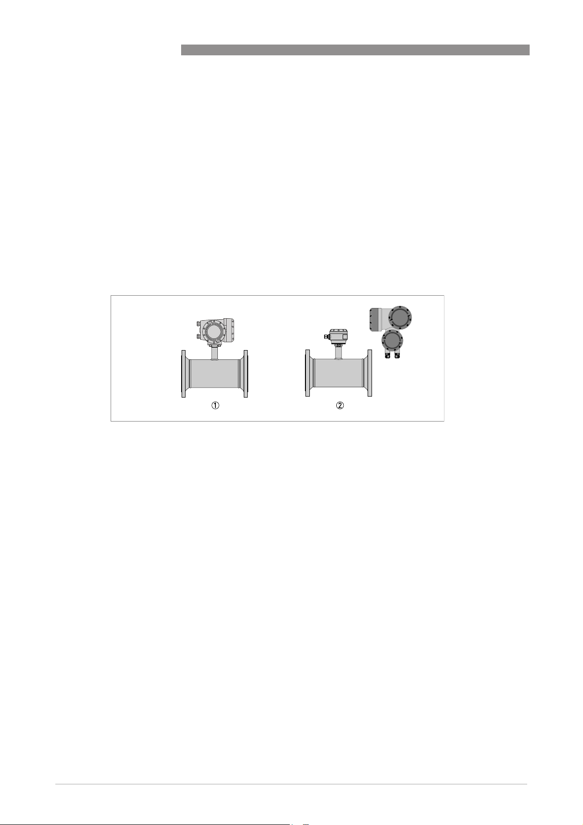
The following versions are available:
• Compact version (the signal converter is mounted directly on the measuring sensor)
• Remote version (electrical connection to the measuring sensor via signal cable)
OPTISONIC 3400
1 Compact version
2 Remote version
6
www.krohne.com 02/2015 - QS OPTISONIC 3400 - 4002741204-R04 en
Page 7
OPTISONIC 3400
2.3 Nameplates
INFORMATION!
Look at the device nameplate to ensure that the device is delivered according to your order.
Check for the correct supply voltage printed on the nameplate.
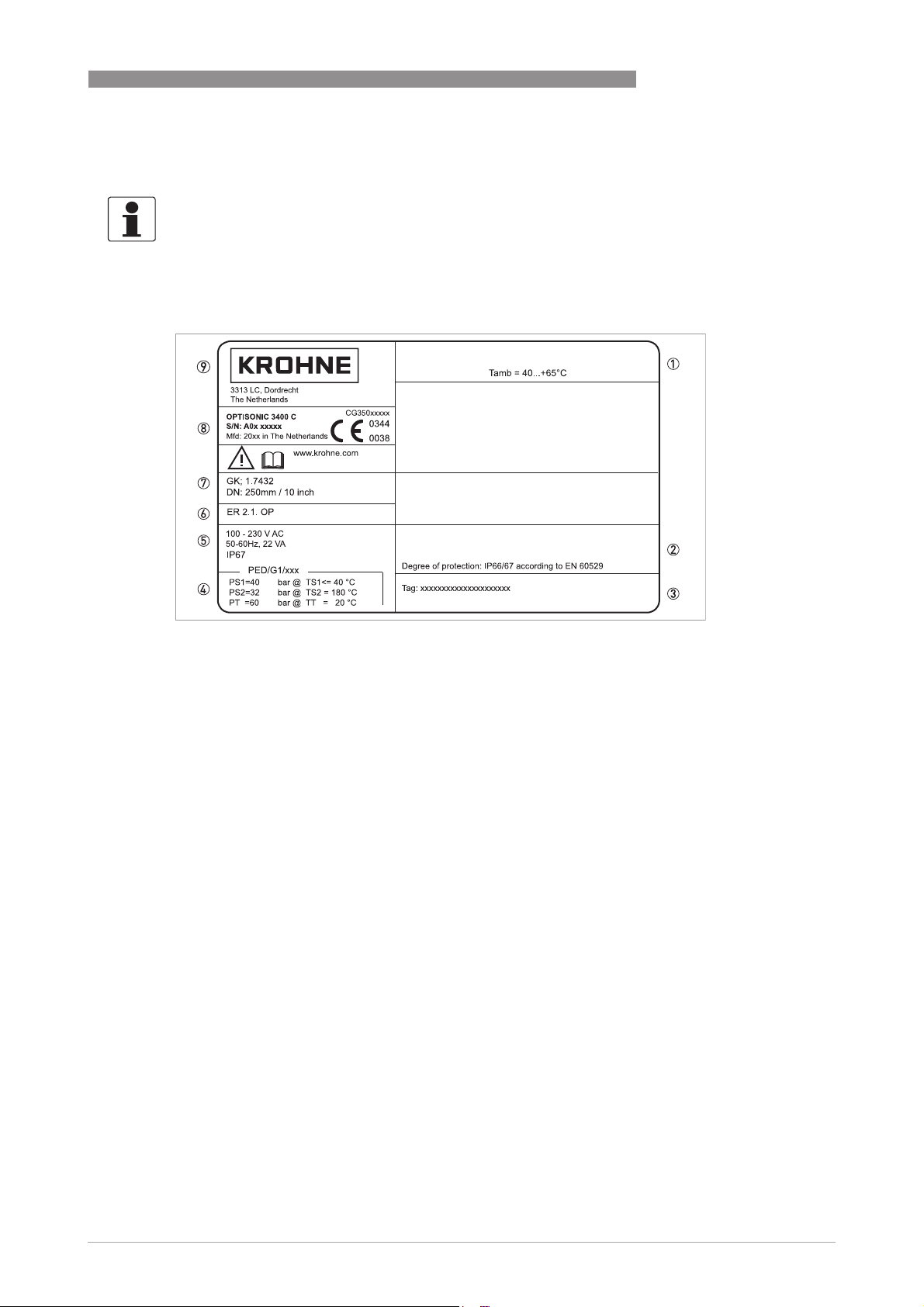
2.3.1 Example of nameplate for the compact version
INSTALLATION
2
Figure 2-2: Example of nameplate for the compact version
1 Ambient temperature
2 Protection class
3 Tag number
4 PED data, type I / II / II or SEP
5 Mains supply data
6 Electronic revision number
7 Calibration data
8 Type designation of the flowmeter and CE sign with number(s) of notified body / bodies
9 Name and address of the manufacturer
www.krohne.com02/2015 - QS OPTISONIC 3400 - 4002741204-R04 en
7
Page 8
2
INSTALLATION
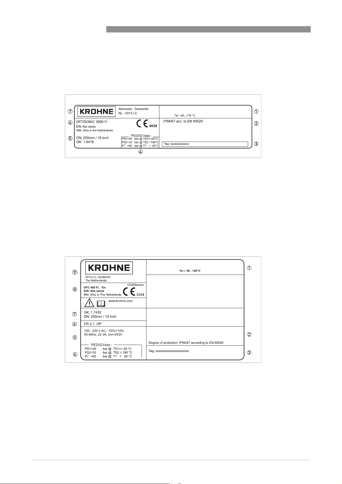
2.3.2 Nameplate for the measuring sensor (field version)
Examples for measuring sensor versions in Standard version.
1. Ambient temperature
2. Protection class
3. Tag number
4. PED data, type I / II / II or SEP
5. Calibration data
6. Type designation of the flowmeter and CE sign with number(s) of notified body / bodies
7. Name and address of the manufacturer
OPTISONIC 3400
2.3.3 Examples of nameplates on the signal converter (field version)
Figure 2-3: Examples of nameplates on the signal converter (field version)
1 Ambient temperature
2 Protection class
3 Tag number
4 PED data, type I / II / II or SEP
5 Mains supply data
6 Electronics revision numbers
7 Calibration data
8 Type designation of the flowmeter and CE sign with number(s) of notified body / bodies
9 Name and address of the manufacturer
8
www.krohne.com 02/2015 - QS OPTISONIC 3400 - 4002741204-R04 en
Page 9
OPTISONIC 3400
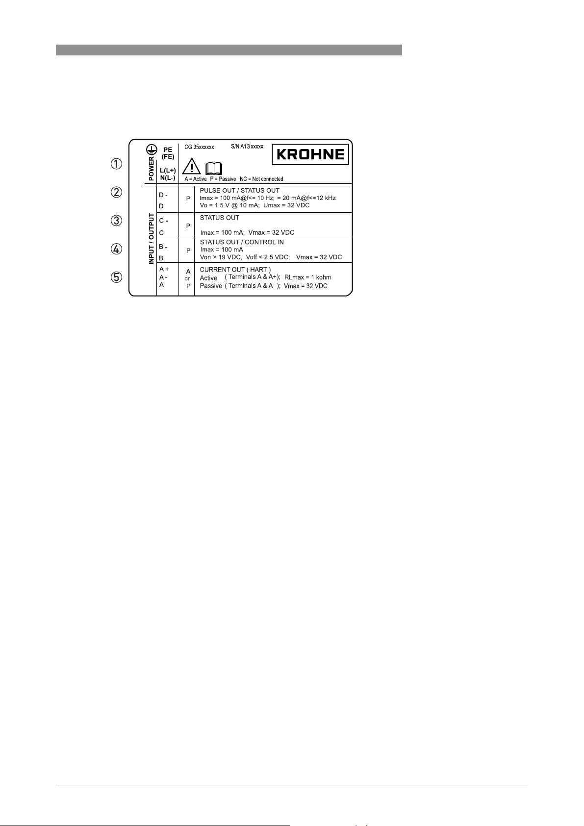
Electrical connection data of inputs/outputs (example of basic version)
Electrical connection data of inputs/outputs (example of basic version)
Electrical connection data of inputs/outputs (example of basic version)Electrical connection data of inputs/outputs (example of basic version)
1 Power supply (AC: L and N, DC: L+ and L-, PE for ≥ 24V AC, FE for ≤ 24 VAC and DC)
2 Connection data of connection terminal D/D-
3 Connection data of connection terminal C/C-
4 Connection data of connection terminal B/B-
5 Connection data of connection terminal A/A-, A+ only operable in basic version
INSTALLATION
2
• A = active mode; the signal converter supplies the power for connection of the subsequent
devices
• P = passive mode; external power supply required for operation of the subsequent devices
• N/C = connection terminals not connected
www.krohne.com02/2015 - QS OPTISONIC 3400 - 4002741204-R04 en
9
Page 10
2
INSTALLATION
2.4 Storage
• Store the device in a dry, dust-free location.
• Avoid continuous direct sunlight.
• Store the device in its original packaging.
• Storage temperature: -50...+70°C / -58...+158°F
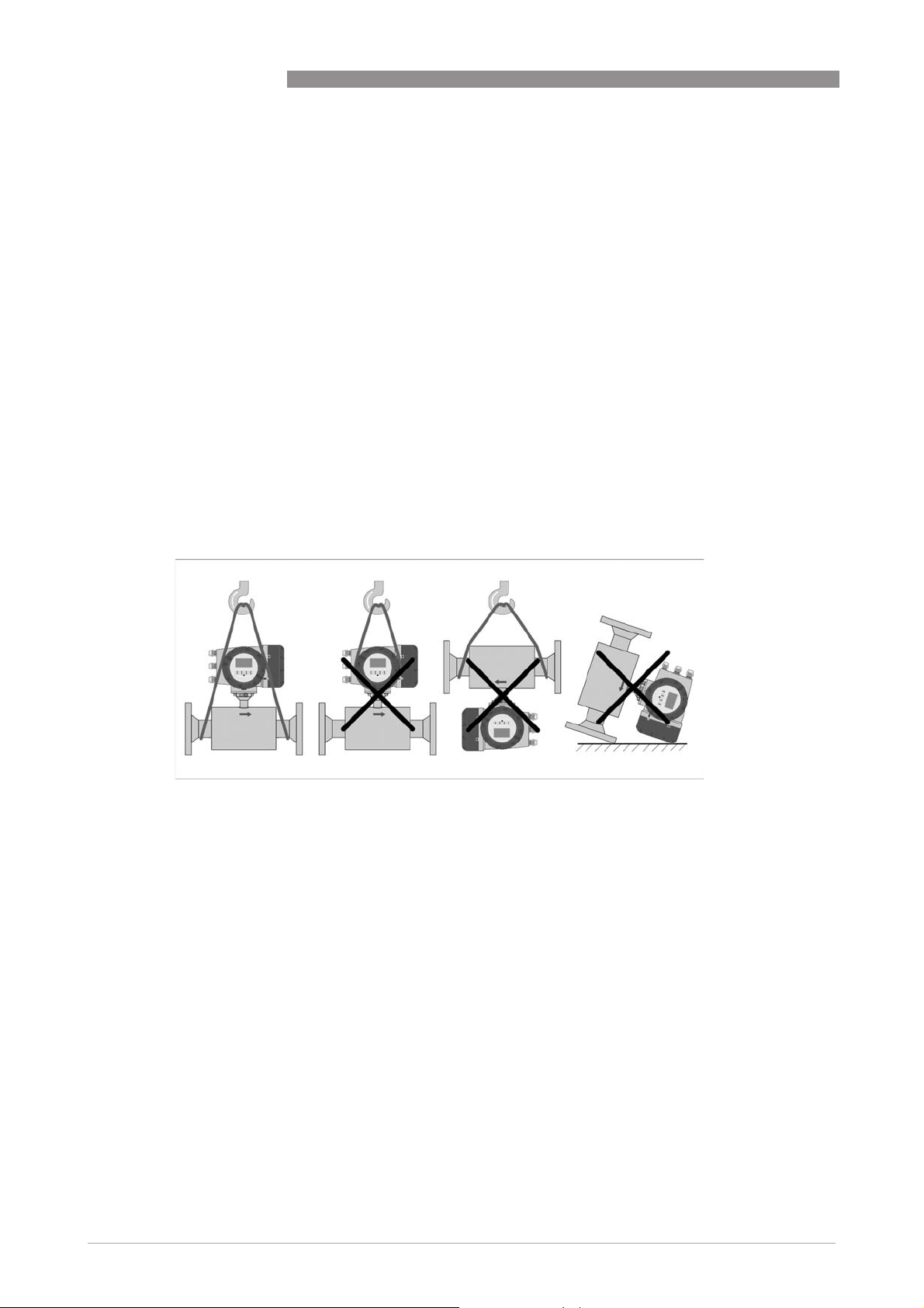
2.5 Transport
Signal converter
• Do not lift the signal converter by the cable glands.
Measuring sensor
• Do not lift the measuring sensor by the connection box.
• Use hoisting belts only.
• To transport flange devices, use lifting straps. Wrap these around both process connections.
OPTISONIC 3400
Figure 2-4: Transport
10
www.krohne.com 02/2015 - QS OPTISONIC 3400 - 4002741204-R04 en
Page 11
OPTISONIC 3400
2.6 Pre-installation requirements
INFORMATION!
To assure a quick, safe and uncomplicated installation, we kindly request you to make provisions
as stated below.
Make sure that you have all necessary tools available:
• Allen key (4 mm)
• Small screwdriver
• Wrench for cable glands
• Wrench for pipe mounting bracket (remote version only) see; on page 17
• Torque wrench for installing flowmeter in pipeline
2.7 General requirements
INFORMATION!
The following precautions must be taken to ensure reliable installation.
•
Make sure that there is adequate space to the sides.
•
Protect the signal converter from direct sunlight and install a sun shade if necessary.
•
Signal converters installed in control cabinets require adequate cooling, e.g. by fan or heat
exchanger.
•
Do not expose the signal converter to intense vibration. The flowmeters are tested for a
vibration level in accordance with IEC 68-2-6.
INSTALLATION
2
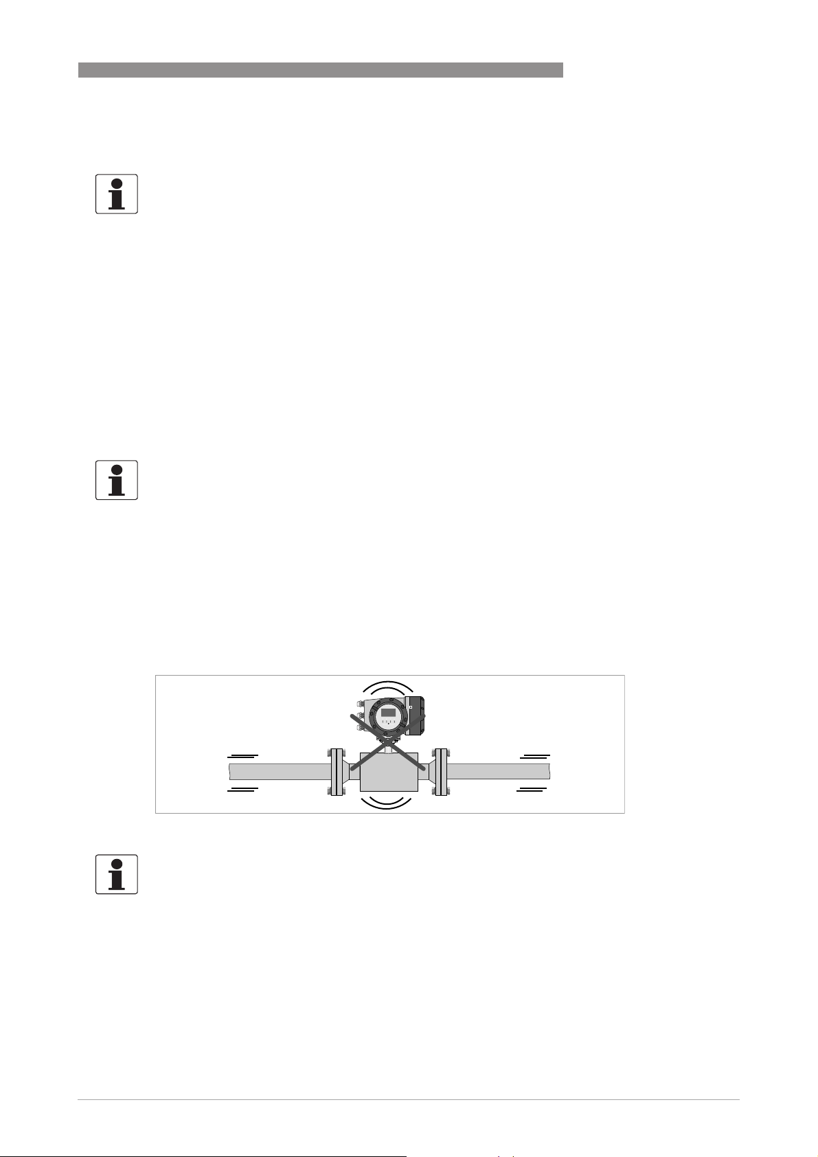
2.7.1 Vibration
Figure 2-5: Avoid vibrations
INFORMATION!
In case of expected vibrations, please install a field version.
www.krohne.com02/2015 - QS OPTISONIC 3400 - 4002741204-R04 en
11
Page 12
2
INSTALLATION
2.8 Installation conditions
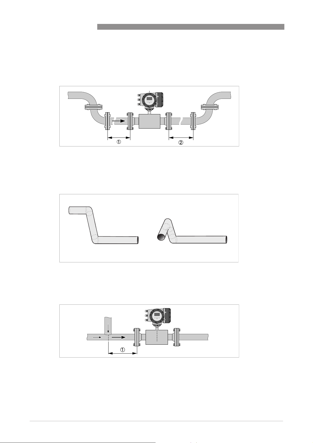
2.8.1 Inlet and outlet
Figure 2-6: Recommended inlet and oulet
1 Refer to chapter "Bends in 2 or 3 dimensions"
2 ≥ 3 DN
2.8.2 Bends in 2 or 3 dimensions
OPTISONIC 3400
Figure 2-7: 2 and 3 dimensional bends, in front of flowmeter
1 Bends in 2 dimensions: ≥ 5 DN; bends in 3 dimensions: ≥ 10 DN
2.8.3 T-section
Figure 2-8: Distance behind a T-section
1 ≥ 5 DN
12
www.krohne.com 02/2015 - QS OPTISONIC 3400 - 4002741204-R04 en
Page 13
OPTISONIC 3400
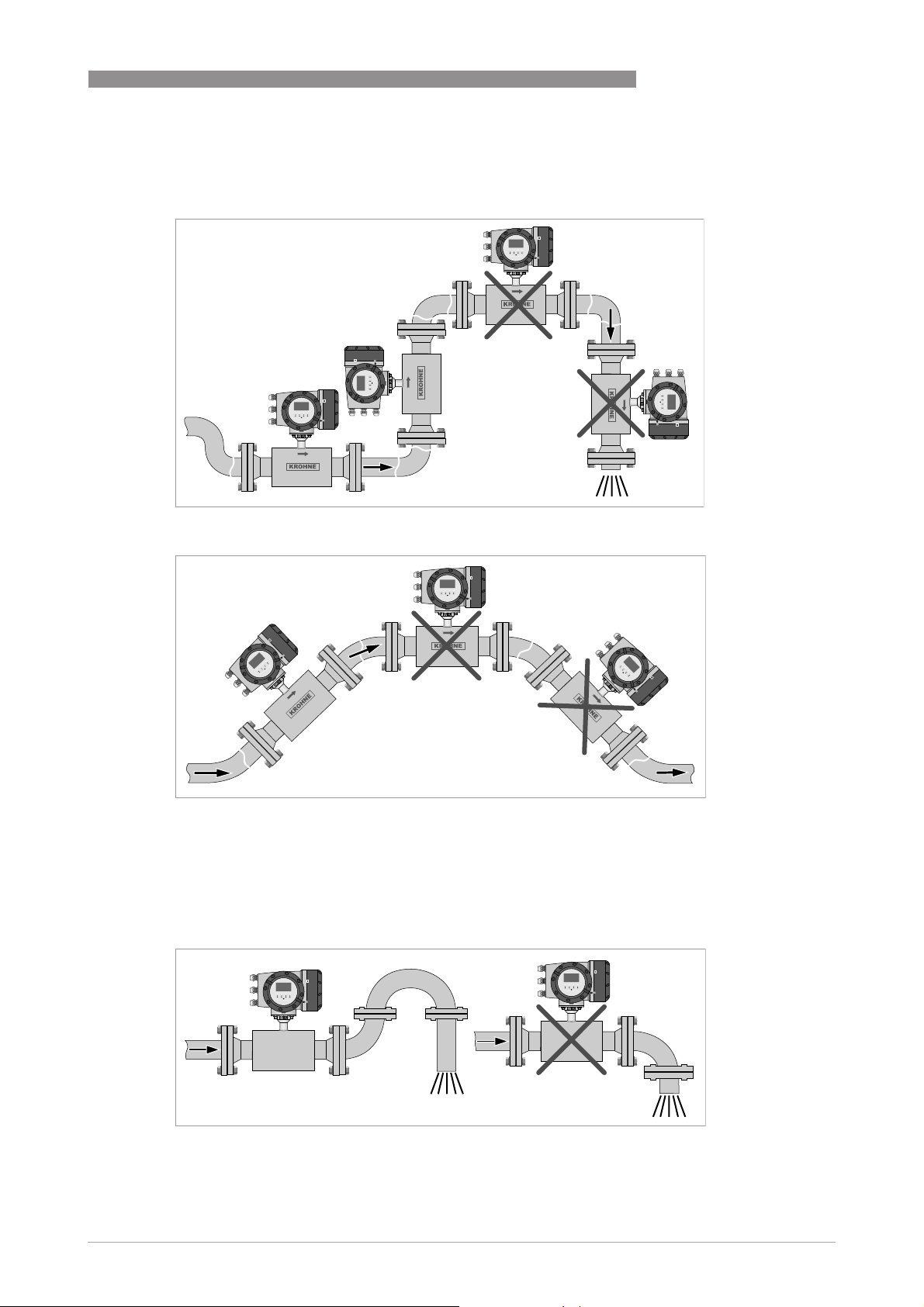
2.9 Bends
Figure 2-9: Installation in bending pipes
INSTALLATION
2
Figure 2-10: Installation in bending pipes
2.10 Open feed or discharge
Figure 2-11: Open discharge
Install meter on a lowered section of the pipe to ensure a full pipe condition through the meter.
www.krohne.com02/2015 - QS OPTISONIC 3400 - 4002741204-R04 en
13
Page 14

2
INSTALLATION
2.11 Position of pump
CAUTION!
Never install flowmeter at a pump suction side in order to avoid cavitation or flashing in the
flowmeter.
Figure 2-12: Position of pump
1 ≥ 15 DN
OPTISONIC 3400
2.12 Control valve
Figure 2-13: Installation in front of a control valve
1 ≥ 20 DN
14
www.krohne.com 02/2015 - QS OPTISONIC 3400 - 4002741204-R04 en
Page 15

OPTISONIC 3400
2.13 Down going pipeline over 5 m /16 ft length
Install air vent downstream of the flowmeter to prevent vacuum. Although this will not harm the
meter, it may cause gases to come out of solution (cavitate) and interfere with proper
measurements.
INSTALLATION
2
Figure 2-14: Down going pipeline over 5 m / 16 ft length
1 ≥ 5 m / 16 ft
2 Install air vent
2.14 Insulation
Figure 2-15: Insulation
1 Connection box
2 Insulation area
WARNING!
The flow sensor can be insulated completely, except for the connection box.
(Ex: maximum temperature, refer to Ex supplement)
For devices used in hazardous area, additional maximum temperature and insulation
precautions apply. Please refer to the Ex documentation!
www.krohne.com02/2015 - QS OPTISONIC 3400 - 4002741204-R04 en
15
Page 16

2
INSTALLATION
2.15 Mounting
2.16 Flange deviation
CAUTION!
Max. permissible misalignment of pipe flange faces: M
accoording ASME B16.5 Individual flanges. See Appendix 12 ; Flange face aligment of the
General Piping Requirements DEP 31.38.01.11-GEN
0.5 degree,
max
OPTISONIC 3400
Figure 2-16: Flange deviation
1 M
max
2.17 Mounting position
Figure 2-17: Horizontal and vertical mounting
16
www.krohne.com 02/2015 - QS OPTISONIC 3400 - 4002741204-R04 en
Page 17

OPTISONIC 3400
2.18 Mounting the field housing, remote version
INFORMATION!
Assembly materials and tools are not part of the delivery. Use the assembly materials and tools
in compliance with the applicable occupational health and safety directives.
2.18.1 Pipe mounting
Figure 2-18: Pipe mounting of the field housing
INSTALLATION
2
1 Fix the signal converter to the pipe.
2 Fasten the signal converter using standard U-bolts and washers.
3 Tighten the nuts.
www.krohne.com02/2015 - QS OPTISONIC 3400 - 4002741204-R04 en
17
Page 18

2
INSTALLATION
2.18.2 Turning the display of the field housing version
OPTISONIC 3400
Figure 2-19: Turning the display of the field housing version
The display of the field housing version can be turned in 90° increments.
1 Unscrew the cover from the display and operation control unit.
2 Using a suitable tool, pull out the two metal puller devices to the left and right of the display.
3 Pull out the display between the two metal puller devices and rotate it to the required position.
4 Slide the display and then the metal puller devices back into the housing.
5 Re-fit the cover and tighten it by hand.
CAUTION!
The ribbon cable of the display must not be folded or twisted repeatedly.
INFORMATION!
Each time a housing cover is opened, the thread should be cleaned and greased. Use only resinfree and acid-free grease.
Ensure that the housing gasket is properly fitted, clean and undamaged.
18
www.krohne.com 02/2015 - QS OPTISONIC 3400 - 4002741204-R04 en
Page 19

OPTISONIC 3400
3.1 Safety instructions
DANGER!
All work on the electrical connections may only be carried out with the power disconnected. Take
note of the voltage data on the nameplate!
DANGER!
Observe the national regulations for electrical installations!
DANGER!
For devices used in hazardous areas, additional safety notes apply; please refer to the Ex
documentation.
WARNING!
Observe without fail the local occupational health and safety regulations. Any work done on the
electrical components of the measuring device may only be carried out by properly trained
specialists.
ELECTRICAL CONNECTIONS
3
INFORMATION!
Look at the device nameplate to ensure that the device is delivered according to your order.
Check for the correct supply voltage printed on the nameplate.
3.2 Signal cable (remote versions only)
The flow sensor is connected to the signal converter via one signal cable, with 6 (labeled) inner
coax cables for the connection of three acoustic paths.
Figure 3-1: Construction of field version
1 Signal converter
2 Open connection box
3 Tool for releasing connectors
4 Marking on cable
5 Insert cable(s) into terminal compartment
www.krohne.com02/2015 - QS OPTISONIC 3400 - 4002741204-R04 en
19
Page 20

3
ELECTRICAL CONNECTIONS
CAUTION!
To ensure smooth functioning, always use the signal cable(s) included in the delivery.
OPTISONIC 3400
Figure 3-2: Clamp the cables on the shielding bush
1 Cables
2 Cable glands
3 Grounding clamps
4 Cable with metal shielding bush
Electrical connection - Standard version
Figure 3-3: Connect the cables in the connection box of the flow sensor
20
www.krohne.com 02/2015 - QS OPTISONIC 3400 - 4002741204-R04 en
Page 21

OPTISONIC 3400
Connection of flow sensor type Cryogenic and XXT
Figure 3-4: Connect the cables in the connection box of the flow sensor
INFORMATION!
Connect the cable on connector with similar numeral marking
ELECTRICAL CONNECTIONS
3
3.3 Power supply
WARNING!
When this device is intended for permanent connection to the mains.
It is required (for example for service) to mount an external switch or circuit breaker near the
device for disconnection from the mains. It shall be easily reachable by the operator and marked
as the disconnecting the device for this equipment.
The switch or circuit breaker and wiring has to be suitable for the application and shall also be in
accordance with the local (safety) requirements of the (building) installation
(e.g. IEC 60947-1 / -3)
DANGER!
For devices used in hazardous areas, additional safety notes apply; please refer to the Ex
documentation.
INFORMATION!
The power terminals in the terminal compartments are equipped with additional hinged lids to
prevent accidental contact.
1 100...230 VAC (-15% / +10%), 22 VA
2 24 VDC (-55% / +30%), 12 W
3 24 VAC/DC (AC: -15% / +10%; DC: -25% / +30%), 22 VA or 12 W
www.krohne.com02/2015 - QS OPTISONIC 3400 - 4002741204-R04 en
21
Page 22

3
ELECTRICAL CONNECTIONS
DANGER!
The device must be grounded in accordance with regulations in order to protect personnel
against electric shocks.
100...230 VAC (tolerance range: -15% / +10%)
• Note the power supply voltage and frequency (50...60 Hz) on the nameplate.
• The protective ground terminal PE
clamp terminal in the terminal compartment of the signal converter
INFORMATION!
240 VAC+5% is included in the tolerance range.
24 VDC (tolerance range: -55% / +30%)
24 VAC/DC (tolerance ranges: AC: -15% / +10%; DC: -25% / +30%)
• Note the data on the nameplate!
• For measurement process reasons, a functional ground FE
separate U-clamp terminal in the terminal compartment of the signal converter.
• When connecting to functional extra-low voltages, provide a facility for protective separation
(PELV) (acc. to VDE 0100 / VDE 0106 and/or IEC 364 / IEC 536 or relevant national
regulations).
OPTISONIC 3400
PE of the power supply must be connected to the separate U-
PEPE
FE must be connected to the
FEFE
INFORMATION!
For 24 VDC, 12 VDC-10% is included in the tolerance range.
3.4 Laying electrical cables correctly
Figure 3-5: Protect housing from dust and water
1 Lay the cable in a loop just before the housing.
2 Tighten the screw connection of the cable entry securely.
3 Never mount the housing with the cable entries facing upwards.
4 Seal cable entries that are not needed with a plug.
22
www.krohne.com 02/2015 - QS OPTISONIC 3400 - 4002741204-R04 en
Page 23

OPTISONIC 3400
3.5 Inputs and outputs, overview
3.5.1 Combinations of the inputs/outputs (I/Os)
This signal converter is available with various input/output combinations.
Basic version
• Has 1 current output, 1 pulse output and 2 status outputs / limit switches.
• The pulse output can be set as status output/limit switch and one of the status outputs as a
control input.
Ex i version
• Depending on the task, the device can be configured with various output modules.
• Current outputs can be active or passive.
• Optionally available also with Foundation Fieldbus and Profibus PA
Modular version
• Depending on the task, the device can be configured with various output modules.
ELECTRICAL CONNECTIONS
3
Bus systems
• The device allows intrinsically safe and non intrinsically safe bus interfaces in combination
with additional modules.
• For connection and operation of bus systems, please note the separate documentation.
Ex option
• For hazardous areas, all of the input/output variants for the housing designs C and F with
terminal compartment in the Ex d (pressure-resistant casing) or Ex e (increased safety)
versions can be delivered.
• Please refer to the separate instructions for connection and operation of the Ex-devices.
www.krohne.com02/2015 - QS OPTISONIC 3400 - 4002741204-R04 en
23
Page 24

3
ELECTRICAL CONNECTIONS
3.5.2 Description of the CG number
Figure 3-6: Marking (CG number) of the electronics module and input/output variants
1 ID number:5
2 ID number: 0 = standard
3 Power supply option
4 Display (language versions)
5 Input/output version (I/O)
6 1st optional module for connection terminal A
7 2nd optional module for connection terminal B
The last 3 digits of the CG number (5, 6 and 7) indicate the assignment of the terminal
connections. Please refer to the following examples.
Examples for CG number
OPTISONIC 3400
CG 350 x1 100 100...230 VAC & standard display; basic I/O: Ia or Ip & Sp/Cp & Sp & Pp/S
p
CG 350 x1 7FK 100...230 VAC & standard display; modular I/O: Ia & PN/SN and optional module PN/SN & C
CG 350 x1 4EB 24 VDC & standard display; modular I/O: Ia & Pa/Sa and optional module Pp/Sp & I
p
Description of abbreviations and CG identifier for possible optional modules
on terminals A and B
Abbreviation Identifier for CG No. Description
I
a
I
p
Pa / S
a
Pp / S
p
PN / S
N
C
a
C
p
C
N
- 8 No additional module installed
- 0 No further module possible
A Active current output
B Passive current output
C Active pulse output, frequency output, status output or limit switch
(changeable)
E Passive pulse output, frequency output, status output or limit switch
(changeable)
F Passive pulse output, frequency output, status output or limit switch acc.
to NAMUR (changeable)
G Active control input
K Passive control input
H Active control input to NAMUR
Signal converter monitors cable breaks and short circuits acc. to
EN 60947-5-6. Errors indicated on LC display. Error messages possible
via status output.
N
24
www.krohne.com 02/2015 - QS OPTISONIC 3400 - 4002741204-R04 en
Page 25

OPTISONIC 3400
3.5.3 Fixed, non-alterable input/output versions
This signal converter is available with various input/output combinations.
• The grey boxes in the tables denote unassigned or unused connection terminals.
• In the table, only the final digits of the CG no. are depicted.
• Connection terminal A+ is only operable in the basic input/output version.
CG-No. Connection terminals
A+ A A- B B- C C- D D-
Basic in-/output (I/O) (Standard)
1 0 0
Ip + HART® passive
Sp / Cp passive
1
ELECTRICAL CONNECTIONS
2
Sp passive Pp / Sp passive
2
3
Ia + HART® active
1
Ex-i in-/outputs (Option)
2 0 0
3 0 0
2 1 0 Ia active PN / SNNAMUR
passive
C
p
3 1 0 Ia active PN / SNNAMUR
passive
C
p
2 2 0 Ip passive PN / SNNAMUR
Cp passive
3 2 0 Ip passive PN / SNNAMUR
passive
C
p
1 Function changed by reconnecting
2 Changeable
2
2
2
2
Ia + HART® active
Ip + HART® passive
Ia + HART® active
Ip + HART® passive
Ia + HART® active
Ip + HART® passive
PN / SN NAMUR
PN / SN NAMUR
PN / SN NAMUR
PN / SN NAMUR
PN / SNNAMUR
PN / SNNAMUR
2
2
2
2
2
2
www.krohne.com02/2015 - QS OPTISONIC 3400 - 4002741204-R04 en
25
Page 26

3
ELECTRICAL CONNECTIONS
3.5.4 Alterable input/output versions
This signal converter is available with various input/output combinations.
• The grey boxes in the tables denote unassigned or unused connection terminals.
• In the table, only the final digits of the CG no. are depicted.
• Term. = (connection) terminal
CG no. Connection terminals
A+ A A- B B- C C- D D-
Modular IOs (option)
4 _ _ max. 2 optional modules for term. A + B
8 _ _ max. 2 optional modules for term. A + B
6 _ _ max. 2 optional modules for term. A + B
B _ _ max. 2 optional modules for term. A + B
7 _ _ max. 2 optional modules for term. A + B
C _ _ max. 2 optional modules for term. A + B
Ia + HART® active
Ip + HART® passive
Ia + HART® active
Ip + HART® passive
Ia + HART® active
Ip + HART® passive
OPTISONIC 3400
Pa / Sa active
Pa / Sa active
Pp / Sp passive
Pp / Sp passive
PN / SN NAMUR
PN / SN NAMUR
1
1
1
1
1
1
PROFIBUS PA/DP
D _ _ max. 2 optional modules for term. A + B PA+ (2) PA- (2) PA+ (1) PA- (1)
F _ _ max. 2 optional modules for term. A + B PA+ (2) PA- (2) PA+ (1) PA- (1)
FOUNDATION Fieldbus (option)
E _ _ max. 2 optional modules for term. A + B V/D+ (2) V/D- (2) V/D+ (1) V/D- (1)
Modbus (option)
G _ _
2
1 changeable
2 not activated bus terminator
max. 2 optional modules for term. A + B CommonSign. B
(D1)
Sign. A
(D0)
26
www.krohne.com 02/2015 - QS OPTISONIC 3400 - 4002741204-R04 en
Page 27

OPTISONIC 3400
4.1 Dimensions and weights
Remote version
Remote version a = 88 mm / 3.5"
Remote versionRemote version
Compact version
Compact version a = 155 mm / 6.1"
Compact versionCompact version
TECHNICAL DATA
b = 139 mm / 5.5"
c = 106 mm / 4.2"
Total height = H + a
b = 230 mm / 9.1"
c = 260 mm / 10.2"
Total height = H + a
1
2
1
2
4
1 The value may vary depending on the used cable glands.
2 The value depends on version
4.2 Variants
Standard version and
Standard version and
Standard version and Standard version and
Extended temperature -
Extended temperature -
Extended temperature - Extended temperature High Viscosity -
High Viscosity -
High Viscosity - High Viscosity -
Cryogenic versions;
Cryogenic versions;
Cryogenic versions;Cryogenic versions;
≤ DN300 / 12"
DN300 / 12"
DN300 / 12" DN300 / 12"
Standard version;
Standard version;
Standard version;Standard version;
≥ DN350 / 14"
DN350 / 14"
DN350 / 14" DN350 / 14"
Extended temperature -
Extended temperature -
Extended temperature - Extended temperature High Viscosity -
High Viscosity -
High Viscosity - High Viscosity -
Cryogenic version;
Cryogenic version;
Cryogenic version; Cryogenic version;
≥ DN350 / 14"
DN350 / 14"
DN350 / 14" DN350 / 14"
DIN: L= 250...500 mm /
9.8"...19.7"
ANSI: L= 250...500 mm /
9.8"...19.7"
* for Cryo - HV - XXT
versions;
ANSI: L= 250...550 mm /
9.8"...21.7"
DIN: L= 500..600 mm /
19.7"...23.6"
ANSI: L= 700...800 mm /
27.6"...31.5"
DIN: L= 500...750 mm /
19.7"...29.5"
ANSI: L= 700...850 mm /
27.6"...33.5"
For all dimensions and options; see tables on next pages (tables not final)
Note; the cCSA versions ( DN25...65 / 1...2.5") are manufactured with a heavy duty neck (SS)
which is 3.6 mm / 0.14 inch higher.
www.krohne.com02/2015 - QS OPTISONIC 3400 - 4002741204-R04 en
27
Page 28

4
TECHNICAL DATA
4.3 Standard flow sensor
The following dimensions are applicable for the OPTISONIC 3400 in compact and remote
versions;
EN1092-1; Standard variant - PN40
OPTISONIC 3400
Nominal
Dimensions [mm], Approx weight
size
DN L H W Di CS Di SS CS SS
25 250 155 115 27 27 8 8
32 260 156 140 35 35 9 10
40 270 173 150 39 41 11 14
50 300 193 165 53 53 14 17
65 300 203 185 63 63 18 19
80 300 238 200 78 81 17 18
100 350 268 235 102 104 24 24
125 350 297 270 127 130 30 29
150 400 326 300 154 158 37 37
200 400 427 375 207 207 63 63
250 500 492 450 260 260 100 100
300 500 547 515 308 308 140 140
EN1092-1; Standard variant - PN25
Nominal
size
Dimensions [mm] Approximate weight
[kg]
[kg]
28
DN L H W Di CS Di SS CS SS
100 350 268 235 102 104 24 23
125 350 297 270 127 130 30 29
150 400 326 300 154 158 37 37
200 400 419 360 207 207 61 61
250 450 479 425 255 255 80 80
300 500 532 485 305 305 102 102
350 500 539 555 330 330 126 126
400 600 596 620 379 379 172 167
450 700 654 670 441 441 199 199
500 700 707 730 488 488 252 252
600 800 817 845 588 588 335 355
www.krohne.com 02/2015 - QS OPTISONIC 3400 - 4002741204-R04 en
Page 29

OPTISONIC 3400
EN1092-1; Standard variant - PN16
TECHNICAL DATA
4
Nominal
Dimensions [mm] Approximate weight
size
DN L H W Di CS Di SS CS SS
100 350 261 220 102 104 20 19
125 350 287 250 127 130 20 20
150 350 319 285 154 158 30 29
200 400 409 340 207 207 51 47
250 400 469 405 255 255 64 64
300 500 520 460 305 305 84 84
EN1092-1; Standard variant - PN10
Nominal
size
DN L H W Di CS Di SS CS SS
200 400 409 340 207 207 48 48
250 400 464 395 255 255 55 55
300 500 512 445 305 305 71 71
350 500 517 505 341 341 69 69
400 600 572 565 388 388 90 90
450 600 623 615 441 441 97 101
500 600 674 670 487 487 118 118
600 600 779 780 585 585 157 157
Dimensions [mm] Approximate weight
[kg]
[kg]
www.krohne.com02/2015 - QS OPTISONIC 3400 - 4002741204-R04 en
29
Page 30

4
TECHNICAL DATA
ASME 150 lb Standard variant
OPTISONIC 3400
Nom.
size
Dimensions Inner diameter
[Di]
Approximate weight
L H W CS / SS 1 CS SS
[inch] [mm] [inch] [mm] [inch] [mm] [inch] [mm] [lb] kg] [lb] [kg]
1 9,8 250 6,0 152 4,3 108 1,1 27 20 9 22 10
1¼ 10,2 260 6,3 161 4,6 117 1,4 35 22 10 22 10
1½ 10,6 270 6,9 174 5,0 127 1,5 1 39 1 26 12 26 12
2 11,8 300 7,4 187 6,0 152 2,1 53 33 15 35 16
2½ 11,8 300 8,7 221 7,0 178 2,5 63 42 19 44 20
3 13,8 350 9,2 233 7,5 191 3,1 78 44 20 44 20
4 13,8 350 10,4 265 9,0 229 4,0 102 57 26 60 27
5 13,8 350 11,4 289 10,0 254 5,0 128 71 32 73 33
6 15,7 400 12,4 316 11,0 279 6,1 154 88 40 90 41
8 15,7 400 16,1 408 13,5 343 8,0 203 110 50 108 49
10 19,7 500 18,5 470 16,0 406 10,0 255 161 73 150 68
12 19,7 500 20,9 531 19,0 483 12,0 305 214 97 209 95
14 27,6 700 20,9 531 21,0 533 13,3 337 260 118 249 113
16 31,5 800 23,2 589 23,5 597 15,3 388 342 155 315 143
18 31,5 800 25,0 635 25,0 635 17,2 438 406 184 348 158
20 31,5 800 27,2 692 27,5 699 19,3 489 489 222 448 203
24 31,5 800 31,5 801 32,0 813 23,0 1 584 1 761 345 591 268
28 35,4 900 35,8 909 36,5 927 27,1 1 687 1 1052 477 - 32 39,4 1000 40,4 1027 41,8 1061 30,8 1 783 1 1598 725 - 36 43,3 1100 39,5 1004 46,0 1168 34,8 1 884 1 2006 910 - 40 47,2 1200 48,9 1243 50,8 1289 38,6 1 980 1 2621 1189 - -
1 Inner Diameter SS differs from CS, consult KROHNE for more information
30
www.krohne.com 02/2015 - QS OPTISONIC 3400 - 4002741204-R04 en
Page 31

OPTISONIC 3400
ASME 300 lb Standard variant
TECHNICAL DATA
4
Nom.
size
Dimensions Inner diameter
[Di]
Approximate weight
L H W CS / SS 1 CS SS
[inch] [mm] [inch] [mm] [inch] [mm] [inch] [mm] [lb] [kg] [lb] [kg]
1 9,8 250 6,3 160 4,9 124 1,1 27 22 10 24 11
1¼ 10,2 260 6,6 169 5,3 133 1,4 35 22 10 22 10
1½ 10,6 270 6,9 175 6,1 155 1,6 41 31 14 31 14
2 11,8 300 7,6 194 6,5 165 2,1 53 35 16 37 17
2½ 11,8 300 9,0 227 7,5 191 2,5 63 44 20 44 20
3 13,8 350 9,6 243 8,3 210 3,1 78 53 24 55 25
4 15,7 400 10,9 278 10,0 254 4,0 102 79 36 82 37
5 15,7 400 11,9 301 11,0 279 5,0 128 97 44 99 45
6 17,7 450 13,2 335 12,5 318 6,1 154 128 58 130 59
8 17,7 450 16,8 427 15,0 381 8,0 203 190 86 179 81
10 19,7 500 19,2 489 17,5 445 9.7 1 248 1 280 127 256 116
12 23,6 600 21,4 544 20,5 521 11.8 1 299 1 421 191 388 176
14 27,6 700 22,0 560 23,0 584 13.1 1 333 1 489 222 467 212
16 31,5 800 24,3 617 25,5 648 15,0 381 688 312 642 291
18 31,5 800 26,5 674 28,0 711 16,5 1 419 1 882 400 811 368
20 31,5 800 28,8 731 30,5 775 18,4 1 467 1 1065 483 955 433
24 31,5 800 33,5 852 36,0 914 22,1 1 560 1 1537 697 1413 641
1 Inner Diameter SS differs from CS, consult KROHNE for more information
www.krohne.com02/2015 - QS OPTISONIC 3400 - 4002741204-R04 en
31
Page 32

4
TECHNICAL DATA
ASME 600 lb Standard variant
OPTISONIC 3400
Nom.
size
Dimensions Inner diameter
[Di]
Approximate weight
L H W CS / SS 1 CS SS
[inch] [mm] [inch] [mm] [inch] [mm] [inch] [mm] [lb] [kg] [lb] [kg]
1 10,6 270 6,3 160 4,9 124 1,1 27 24 11 24 11
1¼ 10,6 270 6,6 169 5,3 133 1,4 35 24 11 24 11
1½ 11,4 290 7,4 189 6,1 155 1,5 1 39 1 33 15 33 15
2 13,0 330 7,6 194 6,5 165 2,1 53 40 18 40 18
2½ 13,0 330 9,0 227 7,5 191 2,5 63 51 23 51 23
3 15,7 400 9,6 243 8,3 210 2,9 74 62 28 64 29
4 15,7 400 11,3 287 10,8 273 3,6 1 92 1 110 50 108 49
5 19,7 500 12,9 327 13,0 330 4,8 122 172 78 174 79
6 19,7 500 13,9 354 14,0 356 5,5 1 140 1 223 101 216 98
8 19,7 500 17,6 446 16,5 419 7,6 194 298 135 302 137
10 23,6 600 20,5 521 20,0 508 9,6 243 527 239 487 221
12 23,6 600 23,0 583 22,0 559 11,4 289 628 285 586 266
14 27,6 700 22,4 569 23,8 603 12,1 1 308 1 767 348 714 324
16 31,5 800 25,0 636 27,0 686 13,9 1 354 1 1093 496 1010 458
18 31,5 800 27,2 690 29,3 743 15,7 1 398 1 1338 607 1210 549
20 35,4 900 29,5 750 32,0 813 17,4 1 443 1 1757 797 1601 726
24 35,4 900 34,0 865 37,0 940 20,9 1 532 1 2480 1125 2238 1015
1 Inner Diameter SS differs from CS, consult KROHNE for more information
32
www.krohne.com 02/2015 - QS OPTISONIC 3400 - 4002741204-R04 en
Page 33

OPTISONIC 3400
ASME 900 lb Standard variant
TECHNICAL DATA
4
Nom.
size
Dimensions Inner diameter
[Di]
Approximate weight
L H W CS / SS 1 CS SS
[inch] [mm] [inch] [mm] [inch] [mm] [inch] [mm] [lb] [kg] [lb] [kg]
1 11,8 300 7,2 183 5,9 149 1,1 27 2 2 24 11
1½ 11,8 300 7,8 198 7,0 178 1,6 41 2 2 33 15
2 14,6 370 9,0 230 8,5 216 2,1 53 2 2 64 29
3 17,7 450 10,7 271 9,5 241 2,6 1 67 1 93 42 95 43
4 17,7 450 12,1 309 11,5 292 3,4 1 87 1 143 65 137 62
6 23,6 600 14,9 379 15,0 381 5,2 1 132 1 309 140 306 139
8 31,5 800 19,3 490 18,5 470 7,0 1 178 1 562 255 540 245
10 31,5 800 22,6 574 21,5 546 9,1 1 230 1 772 350 750 340
12 35,4 900 24,6 625 24,0 610 10,8 1 273 1 1080 490 1025 465
14 35,4 900 23,2 589 25,2 641 11,8 1 300 1 1213 550 1146 520
16 39,4 1000 25,4 646 27,7 705 13,6 1 344 1 1565 710 1433 650
18 39,4 1000 28,0 712 31,0 787 15,3 1 387 1 2050 930 1940 880
20 43,3 1100 30,4 773 33,8 857 17,0 1 432 1 2624 1190 2535 1150
24 51,2 1300 36,1 916 41,0 1041 20,4 1 518 1 4718 2140 4475 2030
1 Inner Diameter SS differs from CS
2 Consult KROHNE for more information
www.krohne.com02/2015 - QS OPTISONIC 3400 - 4002741204-R04 en
33
Page 34

4
TECHNICAL DATA
OPTISONIC 3400
4.4 Variant flow sensor; XXT - High Viscosity and Cryogenic (SS) versions.
The following dimensions are applicable for the OPTISONIC 3400 in compact and remote
versions;
EN1092-1; Extended temperature - High Viscosity and Cryogenic (SS) version - PN40
Nominal
size
Dimensions [mm] Approx weight
[kg]
DN L H W Di CS Di SS CS SS
25 250 155 115 27 27 8 8
32 260 156 140 35 35 10 10
40 270 173 150 39 41 11 13
50 300 193 165 53 53 15 16
65 300 203 185 63 63 19 19
80 350 238 200 81 81 17 18
100 350 268 235 104 104 24 23
125 350 297 270 130 130 30 29
150 400 326 300 158 158 37 36
200 500 427 375 207 207 69 69
250 550 492 450 260 260 101 101
300 550 547 515 308 308 137 137
EN1092-1; Extended temperature - High Viscosity and Cryogenic (SS) version - PN25
Nominal
size
Dimensions [mm] Approximate weight
[kg]
34
DN L H W Di CS Di SS CS SS
100 350 268 235 104 104 29 29
125 350 297 270 130 130 29 29
150 400 326 300 158 158 38 38
200 500 419 360 207 207 61 61
250 550 479 425 260 259 82 82
300 550 532 485 308 308 108 108
350 600 594 555 338 338 148 148
400 650 652 620 389 389 186 186
450 700 702 670 439 439 223 223
500 750 752 730 488 488 290 290
600 800 857 845 586 586 362 362
www.krohne.com 02/2015 - QS OPTISONIC 3400 - 4002741204-R04 en
Page 35

OPTISONIC 3400
EN1092-1; Extended temperature - High Viscosity and Cryogenic (SS) version - PN16
TECHNICAL DATA
4
Nominal
size
Dimensions [mm] Approximate weight
[kg]
DN L H W Di CS Di SS CS SS
100 350 261 220 104 104 23 23
125 350 287 250 130 130 29 29
150 350 319 285 158 158 38 38
200 450 409 340 207 207 49 49
250 500 469 405 260 260 67 68
300 500 520 460 310 310 82 82
EN1092-1; Extended temperature - High Viscosity and Cryogenic (SS) version - PN10
Nominal
size
DN L H W Di CS Di SS CS SS
200 450 409 340 207 207 50 50
250 500 512 445 260 260 66 66
300 500 512 445 310 310 75 75
350 500 559 505 342 342 91 91
400 600 594 565 393 393 114 114
450 600 674 615 443 443 130 130
500 650 722 670 494 494 151 151
600 700 824 780 594 594 195 195
700 750 929 895 694 3 280 3
800 900 1039 1015 794 3 380 3
900 900 1137 1115 889 3 469 3
1000 1000 1247 1230 991 3 595 3
3 TBD - Consult KROHNE for more information
Dimensions [mm] Approximate weight
[kg]
www.krohne.com02/2015 - QS OPTISONIC 3400 - 4002741204-R04 en
35
Page 36

4
TECHNICAL DATA
ASME 150 lb - Extended temperature - High Viscosity and Cryogenic versions
OPTISONIC 3400
Nom.
size
Dimensions Inner diameter
[Di]
Approximate weight
L H W CS / SS 1 CS SS
[inch] [mm] [inch] [mm] [inch] [mm] [inch] [mm] [lb] [kg] [lb] [kg]
1 9,8 250 6,0 152 4,3 108 1,1 27 20 9 20 9
1¼ 10,2 260 6,3 161 4,6 117 1,4 35 24 11 22 10
1½ 10,6 270 6,9 174 5,0 127 1,6 41 26 12 24 11
2 11,8 300 7,4 187 6,0 152 2,1 53 33 15 33 15
2½ 11,8 300 8,7 221 7,0 178 2,5 63 42 19 42 19
3 13,8 350 9,2 233 7,5 191 3,1 78 44 20 44 20
4 13,8 350 10,4 265 9,0 229 4,0 102 57 26 57 26
5 13,8 350 11,4 289 10,0 254 5,0 128 71 32 71 32
6 15,7 400 12,4 316 11,0 279 6,1 154 88 40 88 40
8 17,7 450 16,1 408 13,5 343 8,0 203 119 54 115 52
10 21,7 550 18,5 470 16,0 406 10,0 255 168 76 159 72
12 21,7 550 20,9 531 19,0 483 12,0 305 216 99 216 99
14 27,6 700 20,9 531 21,0 533 13,3 337 311 141 298 135
16 31,5 800 23,2 589 23,5 597 15,3 388 399 181 373 169
18 31,5 800 25,0 635 25,0 635 17,2 438 470 213 414 188
20 31,5 800 27,2 692 27,5 699 19,3 489 560 254 518 235
24 33,5 850 31,5 801 32,0 813 23,3 591 869 394 692 314
28 35,4 900 37,2 945 36,5 927 27,1 1 687 1 1052 527 - 32 37,4 950 41,8 1062 41,8 1061 30,8 1 783 1 1598 769 - 36 41,3 1050 45,8 1163 46,0 1168 34,8 1 884 1 2006 963 - 40 43,3 1100 50,2 1276 50,8 1289 38,6 1 980 1 2621 1225 - -
1 Inner Diameter SS differs from CS, consult KROHNE for more information
36
www.krohne.com 02/2015 - QS OPTISONIC 3400 - 4002741204-R04 en
Page 37

OPTISONIC 3400
ASME 300 lb - Extended temperature - High Viscosity and Cryogenic versions.
TECHNICAL DATA
4
Nom.
size
Dimensions Inner diameter
[Di]
Approximate weight
L H W CS / SS 1 CS SS
[inch] [mm] [inch] [mm] [inch] [mm] [inch] [mm] [lb] [kg] [lb] [kg]
1 9,8 250 6,3 160 4,9 124 1,1 27 22 10 22 10
1¼ 10,2 260 6,6 169 5,3 133 1,4 35 24 11 22 10
1½ 10,6 270 6,9 175 6,1 155 1,6 41 31 14 29 13
2 11,8 300 7,6 194 6,5 165 2,1 53 35 16 35 16
2½ 11,8 300 9,0 227 7,5 191 2,5 63 44 20 44 20
3 13,8 350 9,6 243 8,3 210 3,1 78 53 24 53 24
4 15,7 400 10,9 278 10,0 254 4,0 102 79 36 79 36
5 15,7 400 11,9 301 11,0 279 5,0 128 97 44 97 44
6 17,7 450 13,2 335 12,5 318 6,1 154 128 58 128 58
8 19,7 500 16,8 427 15,0 381 8,0 1 203 1 203 92 187 85
10 21,7 550 19,2 489 17,5 445 9.7 1 248 1 288 135 265 120
12 23,6 600 21,4 544 20,5 521 11.8 1 299 1 428 194 392 178
14 27,6 700 24,0 609 23,0 584 13.1 1 333 1 536 243 518 235
16 31,5 800 26,2 665 25,5 648 15,0 381 699 317 697 316
18 31,5 800 28,4 722 28,0 711 16,5 1 419 1 941 427 871 395
20 31,5 800 30,5 774 30,5 775 18,4 1 467 1 1131 513 1023 464
24 33,5 850 34,8 884 36,0 914 22,1 1 560 1 1658 752 1530 694
1 Inner Diameter SS differs from CS, consult KROHNE for more information
www.krohne.com02/2015 - QS OPTISONIC 3400 - 4002741204-R04 en
37
Page 38

4
TECHNICAL DATA
ASME 600 lb - Extended temperature - High Viscosity and Cryogenic versions.
OPTISONIC 3400
Nom.
size
Dimensions Inner diameter
[Di]
Approximate weight
L H W CS / SS 1 CS SS
[inch] [mm] [inch] [mm] [inch] [mm] [inch] [mm] [lb] [kg] [lb] [kg]
1 10,6 270 6,3 160 4,9 124 1,1 27 24 11 24 11
1¼ 10,6 270 6,6 169 5,3 133 1,4 35 24 11 24 11
1½ 11,4 290 7,4 189 6,1 155 1,5 1 39 1 33 15 33 15
2 13,0 330 7,6 194 6,5 165 2,1 53 40 18 40 18
2½ 13,0 330 9,0 227 7,5 191 2,5 63 51 23 51 23
3 15,7 400 9,6 243 8,3 210 2,9 74 62 28 62 28
4 15,7 400 11,3 287 10,8 273 3,6 1 92 1 110 50 108 49
5 19,7 500 12,9 327 13,0 330 4,8 122 172 78 172 78
6 19,7 500 13,9 354 14,0 356 5,5 1 140 1 223 101 216 98
8 21,7 550 17,6 446 16,5 419 7,6 194 320 145 313 142
10 25,6 650 20,5 521 20,0 508 9,3 1 236 1 536 243 503 228
12 27,6 700 23,0 583 22,0 559 11,1 1 281 1 679 308 631 286
14 29,5 750 24,3 618 23,8 603 12,1 1 308 1 842 382 789 358
16 31,5 800 26,9 684 27,0 686 13,9 1 354 1 1155 524 1074 487
18 33,5 850 29,1 738 29,3 743 15,7 1 398 1 1442 654 1307 593
20 35,4 900 31,2 793 32,0 813 17,4 1 443 1 1832 831 1682 763
24 37,4 950 35,3 896 37,0 940 20,9 1 532 1 2630 1193 2383 1081
1 Inner Diameter SS differs from, consult KROHNE for more information
38
www.krohne.com 02/2015 - QS OPTISONIC 3400 - 4002741204-R04 en
Page 39

OPTISONIC 3400
ASME 900 lb - Extended temperature, High Viscosity and *Cryogenic versions.
TECHNICAL DATA
4
Nom.
size
Dimensions Inner diameter
[Di]
Approximate weight
L H W CS / SS 1 CS SS
[inch] [mm] [inch] [mm] [inch] [mm] [inch] [mm] [lb] [kg] [lb] [kg]
3 17,7 450 10,7 271 9,5 241 2,6 1 67 1 93 42 93 42
4 17,7 450 12,1 309 11,5 292 3,4 1 87 1 143 65 141 64
6 23,6 600 14,9 379 15,0 381 5,2 1 132 1 309 140 304 138
8 31,5 800 18,6 472 18,5 470 7,0 1 178 1 540 245 503 228
10 31,5 800 21,6 550 21,5 546 8,5 1 216 1 809 367 756 343
12 35,4 900 24,0 609 24,0 610 10,1 1 257 1 1129 512 994 451
14 35,4 900 25,1 637 25,2 641 11,2 1 284 1 1303 591 1162 527
16 39,4 1000 27,3 694 27,7 705 13,1 1 333 1 1627 738 1517 688
18 39,4 1000 29,9 760 31,0 787 14,9 1 378 1 2112 958 2022 917
20 39,4 1000 32,6 828 33,8 857 16,5 1 419 1 2599 1179 2399 1088
24 51,2 1300 37,6 955 41,0 1041 19,9 1 505 1 4830 2191 4482 2033
1 Inner Diameter SS differs from CS, consult KROHNE for more information
*Cryogenic and XXT versions not available for 8"...24"
www.krohne.com02/2015 - QS OPTISONIC 3400 - 4002741204-R04 en
39
Page 40

4
TECHNICAL DATA
4.5 Signal converter housing
OPTISONIC 3400
1 Compact housing (C)
2 Field housing (F)
Dimensions and weights in mm and kg
Version Dimensions [mm] Weight
a b c d e g h
C 202 120 155 260 137 - - 4.2
F 202 120 155 - - 295.8 277 5.7
[kg]
Dimensions and weights in inch and lb
Version Dimensions [inch] Weight
a b c d e g h
C 7.75 4.75 6.10 10.20 5.40 - - 9.30
F 7.75 4.75 6.10 - - 11.60 10.90 12.60
[lb]
40
www.krohne.com 02/2015 - QS OPTISONIC 3400 - 4002741204-R04 en
Page 41

OPTISONIC 3400
NOTES
5
www.krohne.com02/2015 - QS OPTISONIC 3400 - 4002741204-R04 en
41
Page 42

KROHNE product overview
•
Electromagnetic flowmeters
•
Variable area flowmeters
•
Ultrasonic flowmeters
•
Mass flowmeters
•
Vortex flowmeters
•
Flow controllers
•
Level meters
•
Temperature assemblies
•
Pressure transmitters
•
Analysis products
•
Products and systems for the oil & gas industry
•
Measuring systems for the marine industry
Head Office KROHNE Messtechnik GmbH
Ludwig-Krohne-Str. 5
47058 Duisburg (Germany)
Tel.:+49 203 301 0
Fax:+49 203 301 103 89
info@krohne.com
The current list of all KROHNE contacts and addresses can be found at:
© KROHNE 02/2015 - QS OPTISONIC 3400 - 4002741204-R04 en - Subject to change without notice.
www.krohne.com
 Loading...