

Page 1
Handbook
Handbook
OPTISONIC 3400
OPTISONIC 3400
OPTISONIC 3400OPTISONIC 3400
HandbookHandbook
Multi purpose, all-round, ultrasonic flowmeter for
liquids in all industrial processes
ER 2.2.1_
© KROHNE 11/2013 - 4002037702 - HB OPTISONIC 3400 -en-R02
Page 2

: IMPRINT :::::::::::::::::::::::::::::::::::::::
All rights reserved. It is prohibited to reproduce this documentation, or any part thereof, without
the prior written authorisation of KROHNE Messtechnik GmbH.
Subject to change without notice.
Copyright 2013 by
KROHNE Messtechnik GmbH - Ludwig-Krohne-Str. 5 - 47058 Duisburg (Germany)
2
www.krohne.com 11/2013 - 4002037702 - HB OPTISONIC 3400 -en-R02
Page 3

OPTISONIC 3400
CONTENTS
1 Safety instructions 7
1.1 Software history ............................................................................................................... 7
1.2 Intended use ..................................................................................................................... 8
1.3 Certification ...................................................................................................................... 8
1.4 Safety instructions from the manufacturer ..................................................................... 9
1.4.1 Copyright and data protection ................................................................................................ 9
1.4.2 Disclaimer ............................................................................................................................... 9
1.4.3 Product liability and warranty .............................................................................................. 10
1.4.4 Information concerning the documentation......................................................................... 10
1.4.5 Warnings and symbols used................................................................................................. 11
1.5 Safety instructions for the operator............................................................................... 11
2 Device description 12
2.1 Scope of delivery............................................................................................................. 12
2.2 Device description .......................................................................................................... 13
2.2.1 Field housing......................................................................................................................... 14
2.3 Nameplates .................................................................................................................... 15
2.3.1 Example of nameplate for the compact version .................................................................. 15
2.3.2 Nameplate for the measuring sensor (field version)........................................................... 16
2.3.3 Examples of nameplates on the signal converter (field version) ........................................ 16
3 Installation 18
3.1 General notes on installation ......................................................................................... 18
3.2 Storage ........................................................................................................................... 18
3.3 Transport ........................................................................................................................ 18
3.4 Pre-installation requirements ....................................................................................... 19
3.5 General requirements .................................................................................................... 19
3.5.1 Vibration ................................................................................................................................ 19
3.6 Installation conditions ....................................................................................................20
3.6.1 Inlet and outlet...................................................................................................................... 20
3.6.2 Bends in 2 or 3 dimensions................................................................................................... 20
3.6.3 T-section ............................................................................................................................... 20
3.6.4 Bends .................................................................................................................................... 21
3.6.5 Open feed or discharge......................................................................................................... 21
3.6.6 Position of pump ................................................................................................................... 22
3.6.7 Control valve ......................................................................................................................... 22
3.6.8 Down going pipeline over 5 m /16 ft length.......................................................................... 23
3.6.9 Insulation............................................................................................................................... 23
3.7 Mounting......................................................................................................................... 24
3.7.1 Flange deviation.................................................................................................................... 24
3.7.2 Mounting position.................................................................................................................. 24
3.8 Mounting the field housing, remote version .................................................................. 25
3.8.1 Pipe mounting ....................................................................................................................... 25
3.8.2 Turning the display of the field housing version .................................................................. 26
4 Electrical connections 27
www.krohne.com11/2013 - 4002037702 - HB OPTISONIC 3400 -en-R02
3
Page 4

CONTENTS
4.1 Safety instructions.......................................................................................................... 27
4.2 Signal cable (remote versions only)............................................................................... 27
4.3 Power supply .................................................................................................................. 29
4.4 Laying electrical cables correctly .................................................................................. 30
4.5 Inputs and outputs, overview ......................................................................................... 31
4.5.1 Combinations of the inputs/outputs (I/Os) ........................................................................... 31
4.5.2 Description of the CG number .............................................................................................. 32
4.5.3 Fixed, non-alterable input/output versions.......................................................................... 33
4.5.4 Alterable input/output versions............................................................................................ 34
4.6 Description of the inputs and outputs............................................................................ 35
4.6.1 Control input ......................................................................................................................... 35
4.6.2 Current output ...................................................................................................................... 36
4.6.3 Pulse and frequency output.................................................................................................. 37
4.6.4 Status output and limit switch .............................................................................................. 38
4.7 Connection diagrams of inputs and outputs.................................................................. 39
4.7.1 Important notes..................................................................................................................... 39
4.7.2 Description of the electrical symbols................................................................................... 40
4.7.3 Basic inputs/outputs ............................................................................................................. 41
4.7.4 Modular inputs/outputs and bus systems............................................................................ 44
4.7.5 Ex i inputs/outputs ................................................................................................................ 50
4.7.6 HART
OPTISONIC 3400
®
connection ................................................................................................................ 53
5 Start-up 55
5.1 Starting the signal converter ......................................................................................... 55
5.2 Switching on the power .................................................................................................. 55
6 Operation 56
6.1 Display and operating elements .................................................................................... 56
6.1.1 Display in measuring mode with 2 or 3 measured values ................................................... 57
6.1.2 Display for selection of submenu and functions, 3 lines ..................................................... 58
6.1.3 Display when setting parameters, 4 lines ............................................................................ 58
6.1.4 Display when previewing parameters, 4 lines...................................................................... 59
6.1.5 Using an IR interface (option) ............................................................................................... 59
6.2 Menu structure............................................................................................................... 60
6.3 Function tables ............................................................................................................... 63
6.3.1 Menu A, Quick Setup............................................................................................................. 63
6.3.2 Menu B; test .......................................................................................................................... 65
6.3.3 Menu C; setup ....................................................................................................................... 66
6.3.4 Set free units......................................................................................................................... 78
6.4 Description of functions ................................................................................................. 79
6.4.1 Reset totaliser in the menu "Quick Setup"........................................................................... 79
6.4.2 Deleting error messages in the menu "Quick Setup".......................................................... 79
6.4.3 Diagnosis messages ............................................................................................................. 80
6.4.4 Optical keys ........................................................................................................................... 80
6.4.5 Graphic page ......................................................................................................................... 80
6.4.6 Save settings .........................................................................................................................80
6.4.7 Load settings......................................................................................................................... 80
6.4.8 Passwords............................................................................................................................. 81
6.4.9 Date and time ........................................................................................................................ 81
6.4.10 Quick Access ....................................................................................................................... 81
4
www.krohne.com 11/2013 - 4002037702 - HB OPTISONIC 3400 -en-R02
Page 5

OPTISONIC 3400
6.4.11 Low flow cutoff .................................................................................................................... 81
6.4.12 Time constant...................................................................................................................... 82
6.4.13 Dual phase pulse output ..................................................................................................... 82
6.4.14 Timeouts in programming mode ........................................................................................ 82
6.4.15 Output hardware ................................................................................................................. 82
CONTENTS
6.5 Status messages and diagnostic information................................................................ 83
7 Service 90
7.1 Spare parts availability...................................................................................................90
7.2 Availability of services .................................................................................................... 90
7.3 Returning the device to the manufacturer..................................................................... 90
7.3.1 General information.............................................................................................................. 90
7.3.2 Form (for copying) to accompany a returned device............................................................ 91
7.4 Disposal .......................................................................................................................... 91
8 Technical data 92
8.1 Measuring principle........................................................................................................92
8.2 Technical data................................................................................................................. 93
8.3 Dimensions and weights .............................................................................................. 105
8.3.1 Variants ............................................................................................................................... 105
8.3.2 Standard flow sensor DN300 and smaller ......................................................................... 106
8.3.3 Standard flow sensor DN350 and larger............................................................................ 110
8.3.4 Flow sensor variant DN350 and larger.............................................................................. 112
8.3.5 Signal converter housing .................................................................................................... 113
8.4 Pressure derating......................................................................................................... 114
9 Description of HART interface 115
9.1 General description ...................................................................................................... 115
9.2 Software history ...........................................................................................................115
9.3 Connection variants...................................................................................................... 116
9.3.1 Point-to-Point connection - analogue / digital mode......................................................... 117
9.3.2 Multi-Drop connection (2-wire connection) ....................................................................... 118
9.3.3 Multi-Drop connection (3-wire connection) ....................................................................... 119
9.4 Inputs/outputs and HART® dynamic variables and device variables.......................... 120
9.5 Remote operation......................................................................................................... 121
9.5.1 Online/offline operation ...................................................................................................... 121
9.5.2 Parameters for the basic configuration ............................................................................. 122
9.5.3 Units .................................................................................................................................... 122
9.6 Field Communicator 375/475 (FC 375/475) ................................................................. 122
9.6.1 Installation .......................................................................................................................... 122
9.6.2 Operation............................................................................................................................. 123
9.7 Asset Management Solutions (AMS)............................................................................ 123
9.7.1 Installation .......................................................................................................................... 123
9.7.2 Operation............................................................................................................................. 124
9.8 Process Device Manager (PDM)................................................................................... 124
9.8.1 Installation .......................................................................................................................... 124
9.8.2 Operation............................................................................................................................. 125
9.9 Field Device Manager (FDM) ........................................................................................ 125
www.krohne.com11/2013 - 4002037702 - HB OPTISONIC 3400 -en-R02
5
Page 6

CONTENTS
9.9.1 Installation .......................................................................................................................... 125
9.9.2 Operation............................................................................................................................. 125
OPTISONIC 3400
9.10 Field Device Tool Device Type Manager (FDT DTM) .................................................. 126
9.10.1 Installation ........................................................................................................................ 126
9.10.2 Operation........................................................................................................................... 126
9.11 HART Menu Tree; UFC400.......................................................................................... 126
9.11.1 HART Menu Tree - Field Communicator HART Application............................................. 126
9.11.2 HART Menu Tree AMS - Device's context menu .............................................................. 127
9.11.3 HART Menu Tree PDM - Menu Bar and Working Window ............................................... 128
9.11.4 HART Menu Tree FDM - Device Configuration ................................................................. 129
9.11.5 Description of used abbreviations .................................................................................... 129
9.11.6 Process Variables Root Menu........................................................................................... 130
9.11.7 Process Variables Root Menu Charts............................................................................... 131
9.11.8 Diagnostic Root Menu ....................................................................................................... 133
9.11.9 Device Root Menu.............................................................................................................. 135
9.11.10 Offline Root Menu............................................................................................................ 138
10 Notes 141
6
www.krohne.com 11/2013 - 4002037702 - HB OPTISONIC 3400 -en-R02
Page 7

OPTISONIC 3400
1.1 Software history
For all GDC devices, the "Electronic Revision" (ER) is consulted to document the revision status
of the electronics according to NE 53. It is easy to see from the ER whether any fault repairs or
major changes to the electronic equipment have taken place and what effect they have had on
compatibility.
Changes and effect on compatibility
1 Downwards compatible changes and fault repair with no effect on operation (e.g. spelling
mistakes on display)
2-_ Downwards compatible hardware and/or software change of interfaces:
H
HART® Version 7
P PROFIBUS (pending)
F Foundation Fieldbus
M Modbus
X all interfaces
3-_ Downwards compatible hardware and/or software change of inputs and outputs:
I Current output
F, P Frequency / pulse output
S Status output
C Control input
X all inputs and outputs
4 Downwards compatible changes with new functions
5 Incompatible changes, i.e. electronic equipment must be changed.
SAFETY INSTRUCTIONS 1
INFORMATION!
In the table below, "x" is a placeholder for possible multi-digit alphanumeric combinations,
depending on the available version.
Release date Electronic Revision Changes and
Documentation
compatibility
2013-04 ER 2.2.0_ MA OPTISONIC 3400
2013-09 ER 2.2.1_ 1 MA OPTISONIC 3400
R01
R02
www.krohne.com11/2013 - 4002037702 - HB OPTISONIC 3400 -en-R02
7
Page 8
1 SAFETY INSTRUCTIONS
1.2 Intended use
CAUTION!
Responsibility for the use of the measuring devices with regard to suitability, intended use and
corrosion resistance of the used materials against the measured fluid lies solely with the
operator.
INFORMATION!
The manufacturer is not liable for any damage resulting from improper use or use for other than
the intended purpose.
The OPTISONIC 3400
OPTISONIC 3400 is designed exclusively for measurements on conductive and / or non-
OPTISONIC 3400OPTISONIC 3400
conductive fluids, in closed completely filled pipeline circuits. Excess of contaminations (gas,
particles, 2 phases) disturb the acoustic signal and thus must be avoided.
OPTISONIC 3400
The overall functionality of the OPTISONIC 3400
actual volume flow, mass flow, flow speed, velocity of sound, gain, SNR, totalized flow mass and
diagnosis values.
1.3 Certification
CE marking
The device fulfils the statutory requirements of the following EC directives:
• EMC Directive 2004/108/EC in conjunction with EN 61326-1: 2006
• Low Voltage Directive 2006/95/EC in conjunction with EN 61010-1: 2001
• NAMUR NE 21/04
The manufacturer certifies successful testing of the product by applying the CE marking.
DANGER!
For devices used in hazardous areas, additional safety notes apply; please refer to the Ex
documentation.
OPTISONIC 3400 flowmeter, is the continuous measurement of
OPTISONIC 3400OPTISONIC 3400
8
www.krohne.com 11/2013 - 4002037702 - HB OPTISONIC 3400 -en-R02
Page 9

OPTISONIC 3400
1.4 Safety instructions from the manufacturer
1.4.1 Copyright and data protection
The contents of this document have been created with great care. Nevertheless, we provide no
guarantee that the contents are correct, complete or up-to-date.
The contents and works in this document are subject to copyright. Contributions from third
parties are identified as such. Reproduction, processing, dissemination and any type of use
beyond what is permitted under copyright requires written authorisation from the respective
author and/or the manufacturer.
The manufacturer tries always to observe the copyrights of others, and to draw on works created
in-house or works in the public domain.
The collection of personal data (such as names, street addresses or e-mail addresses) in the
manufacturer's documents is always on a voluntary basis whenever possible. Whenever
feasible, it is always possible to make use of the offerings and services without providing any
personal data.
SAFETY INSTRUCTIONS 1
We draw your attention to the fact that data transmission over the Internet (e.g. when
communicating by e-mail) may involve gaps in security. It is not possible to protect such data
completely against access by third parties.
We hereby expressly prohibit the use of the contact data published as part of our duty to publish
an imprint for the purpose of sending us any advertising or informational materials that we have
not expressly requested.
1.4.2 Disclaimer
The manufacturer will not be liable for any damage of any kind by using its product, including,
but not limited to direct, indirect or incidental and consequential damages.
This disclaimer does not apply in case the manufacturer has acted on purpose or with gross
negligence. In the event any applicable law does not allow such limitations on implied warranties
or the exclusion of limitation of certain damages, you may, if such law applies to you, not be
subject to some or all of the above disclaimer, exclusions or limitations.
Any product purchased from the manufacturer is warranted in accordance with the relevant
product documentation and our Terms and Conditions of Sale.
The manufacturer reserves the right to alter the content of its documents, including this
disclaimer in any way, at any time, for any reason, without prior notification, and will not be liable
in any way for possible consequences of such changes.
www.krohne.com11/2013 - 4002037702 - HB OPTISONIC 3400 -en-R02
9
Page 10

1 SAFETY INSTRUCTIONS
1.4.3 Product liability and warranty
The operator shall bear responsibility for the suitability of the device for the specific purpose.
The manufacturer accepts no liability for the consequences of misuse by the operator. Improper
installation and operation of the devices (systems) will cause the warranty to be void. The
respective "Standard Terms and Conditions" which form the basis for the sales contract shall
also apply.
1.4.4 Information concerning the documentation
To prevent any injury to the user or damage to the device it is essential that you read the
information in this document and observe applicable national standards, safety requirements
and accident prevention regulations.
If this document is not in your native language and if you have any problems understanding the
text, we advise you to contact your local office for assistance. The manufacturer can not accept
responsibility for any damage or injury caused by misunderstanding of the information in this
document.
This document is provided to help you establish operating conditions, which will permit safe and
efficient use of this device. Special considerations and precautions are also described in the
document, which appear in the form of underneath icons.
OPTISONIC 3400
10
www.krohne.com 11/2013 - 4002037702 - HB OPTISONIC 3400 -en-R02
Page 11
OPTISONIC 3400
1.4.5 Warnings and symbols used
Safety warnings are indicated by the following symbols.
DANGER!
This information refers to the immediate danger when working with electricity.
DANGER!
This warning refers to the immediate danger of burns caused by heat or hot surfaces.
DANGER!
This warning refers to the immediate danger when using this device in a hazardous atmosphere.
DANGER!
These warnings must be observed without fail. Even partial disregard of this warning can lead to
serious health problems and even death. There is also the risk of seriously damaging the device
or parts of the operator's plant.
SAFETY INSTRUCTIONS 1
WARNING!
Disregarding this safety warning, even if only in part, poses the risk of serious health problems.
There is also the risk of damaging the device or parts of the operator's plant.
CAUTION!
Disregarding these instructions can result in damage to the device or to parts of the operator's
plant.
INFORMATION!
These instructions contain important information for the handling of the device.
LEGAL NOTICE!
This note contains information on statutory directives and standards.
• HANDLING
HANDLING
HANDLINGHANDLING
This symbol designates all instructions for actions to be carried out by the operator in the
specified sequence.
i RESULT
RESULT
RESULTRESULT
This symbol refers to all important consequences of the previous actions.
1.5 Safety instructions for the operator
WARNING!
In general, devices from the manufacturer may only be installed, commissioned, operated and
maintained by properly trained and authorized personnel.
This document is provided to help you establish operating conditions, which will permit safe and
efficient use of this device.
www.krohne.com11/2013 - 4002037702 - HB OPTISONIC 3400 -en-R02
11
Page 12

2 DEVICE DESCRIPTION
2.1 Scope of delivery
INFORMATION!
Do a check of the packing list to make sure that you have all the elements given in the order.
INFORMATION!
Inspect the cartons carefully for damages or signs of rough handling. Report damage to the
carrier and to the local office of the manufacturer.
INFORMATION!
The device will arrive in two cartons. One carton contains the converter and one carton contains
the sensor.
OPTISONIC 3400
Figure 2-1: Scope of delivery - compact version
1 Ordered flowmeter
2 Product documentation
3 Factory calibration certificate
4 CD-ROM with product documentation in available languages
5 Signal cable (remote versions only)
INFORMATION!
Assembly materials and tools are not part of the delivery. Use the assembly materials and tools
in compliance with the applicable occupational health and safety directives.
12
www.krohne.com 11/2013 - 4002037702 - HB OPTISONIC 3400 -en-R02
Page 13
OPTISONIC 3400
2.2 Device description
This ultrasonic flowmeter is designed for the continuous measurement of actual volume flow,
mass flow, flow speed, velocity of sound, gain, SNR and diagnosis value.
Exclusively for measuring conductive and / or non-conductive fluids in closed, completely filled
pipeline circuits.
Your measuring device is supplied ready for operation. The factory settings for the operating
data have been made in accordance with your order specifications.
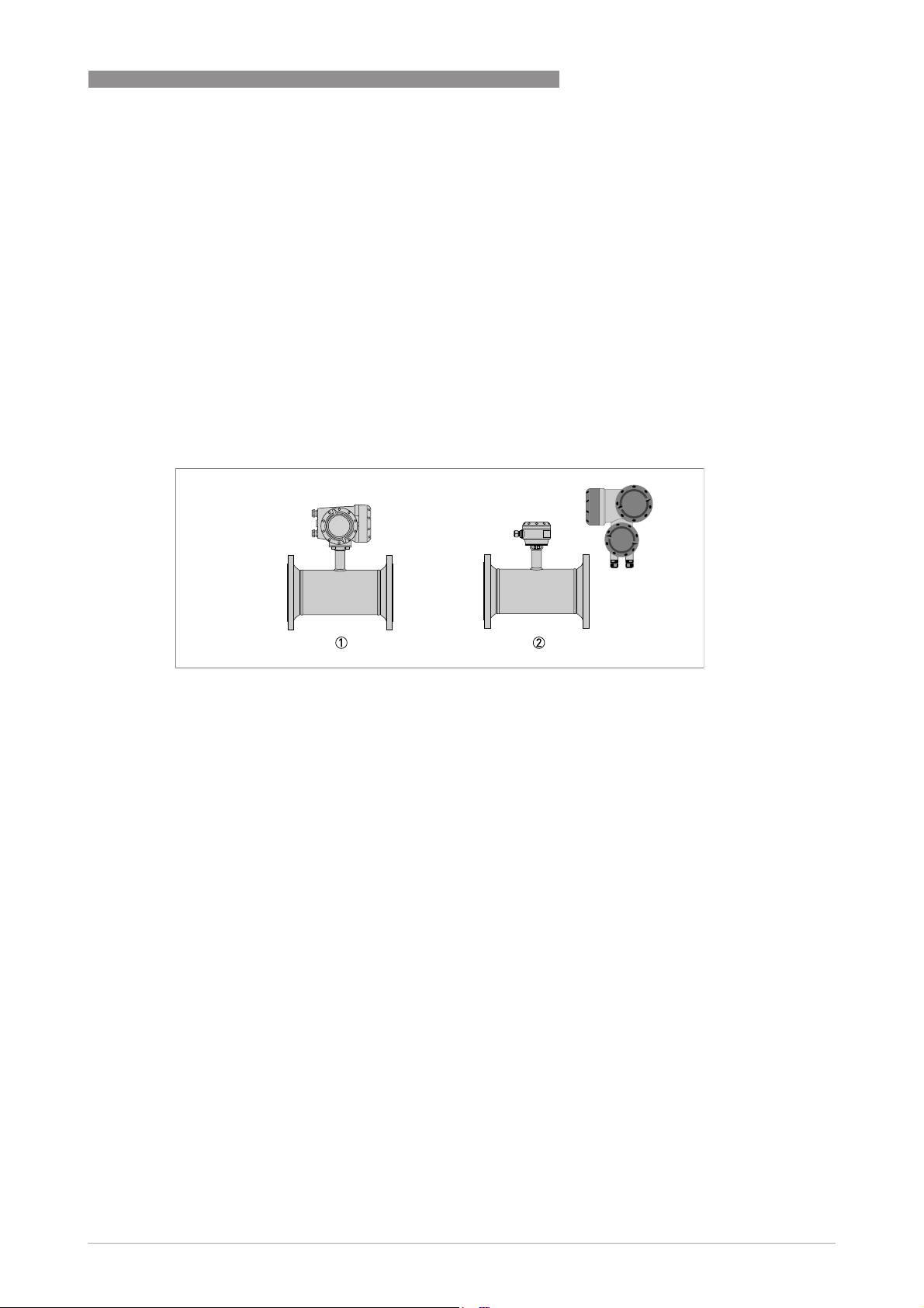
The following version is available:
• Compact version (the signal converter is mounted directly on the measuring sensor)
• Remote version (electrical connection to the measuring sensor via signal cable)
DEVICE DESCRIPTION 2
1 Compact version
2 Remote version
www.krohne.com11/2013 - 4002037702 - HB OPTISONIC 3400 -en-R02
13
Page 14
2 DEVICE DESCRIPTION
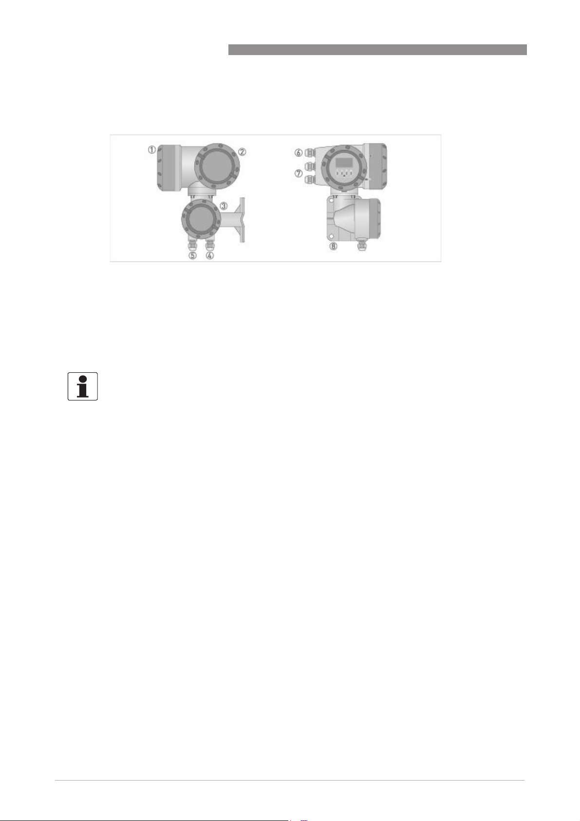
2.2.1 Field housing
Figure 2-2: Construction of the field housing
1 Cover for electronics and display
2 Cover for power supply and inputs/outputs terminal compartment
3 Cover for measuring sensor terminal compartment
4 Use cable entry 4 or 5 for measuring sensor signal cable
5 (see 4)
6 Cable entry for power supply
7 Cable entry for inputs and outputs
8 Mounting plate for pipe and wall mounting
OPTISONIC 3400
INFORMATION!
Each time a housing cover is opened, the thread should be cleaned and greased.
Use only resin-free and acid-free grease.
Ensure that the housing gasket is properly fitted, clean and undamaged.
14
www.krohne.com 11/2013 - 4002037702 - HB OPTISONIC 3400 -en-R02
Page 15
OPTISONIC 3400
2.3 Nameplates
INFORMATION!
Look at the device nameplate to ensure that the device is delivered according to your order.
Check for the correct supply voltage printed on the nameplate.
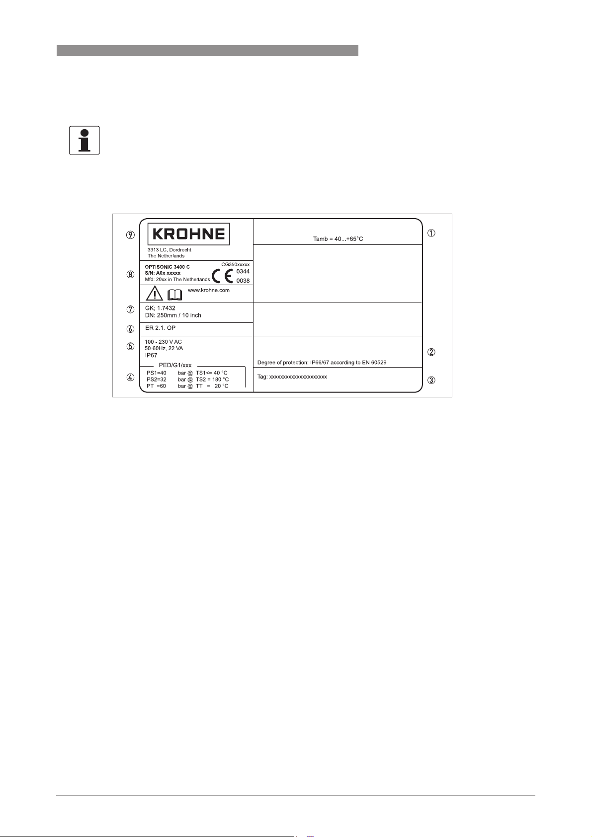
2.3.1 Example of nameplate for the compact version
DEVICE DESCRIPTION 2
Figure 2-3: Example of nameplate for the compact version
1 Ambient temperature
2 Protection class
3 Tag number
4 PED data, type I / II / II or SEP
5 Mains supply data
6 Electronic revision number
7 Calibration data
8 Type designation of the flowmeter and CE sign with number(s) of notified body / bodies
9 Name and address of the manufacturer
www.krohne.com11/2013 - 4002037702 - HB OPTISONIC 3400 -en-R02
15
Page 16
2 DEVICE DESCRIPTION
2.3.2 Nameplate for the measuring sensor (field version)
Examples for measuring sensor versions in Standard version.
1. Ambient temperature
2. Protection class
3. Tag number
4. PED data, type I / II / II or SEP
5. Calibration data
6. Type designation of the flowmeter and CE sign with number(s) of notified body / bodies
7. Name and address of the manufacturer
OPTISONIC 3400
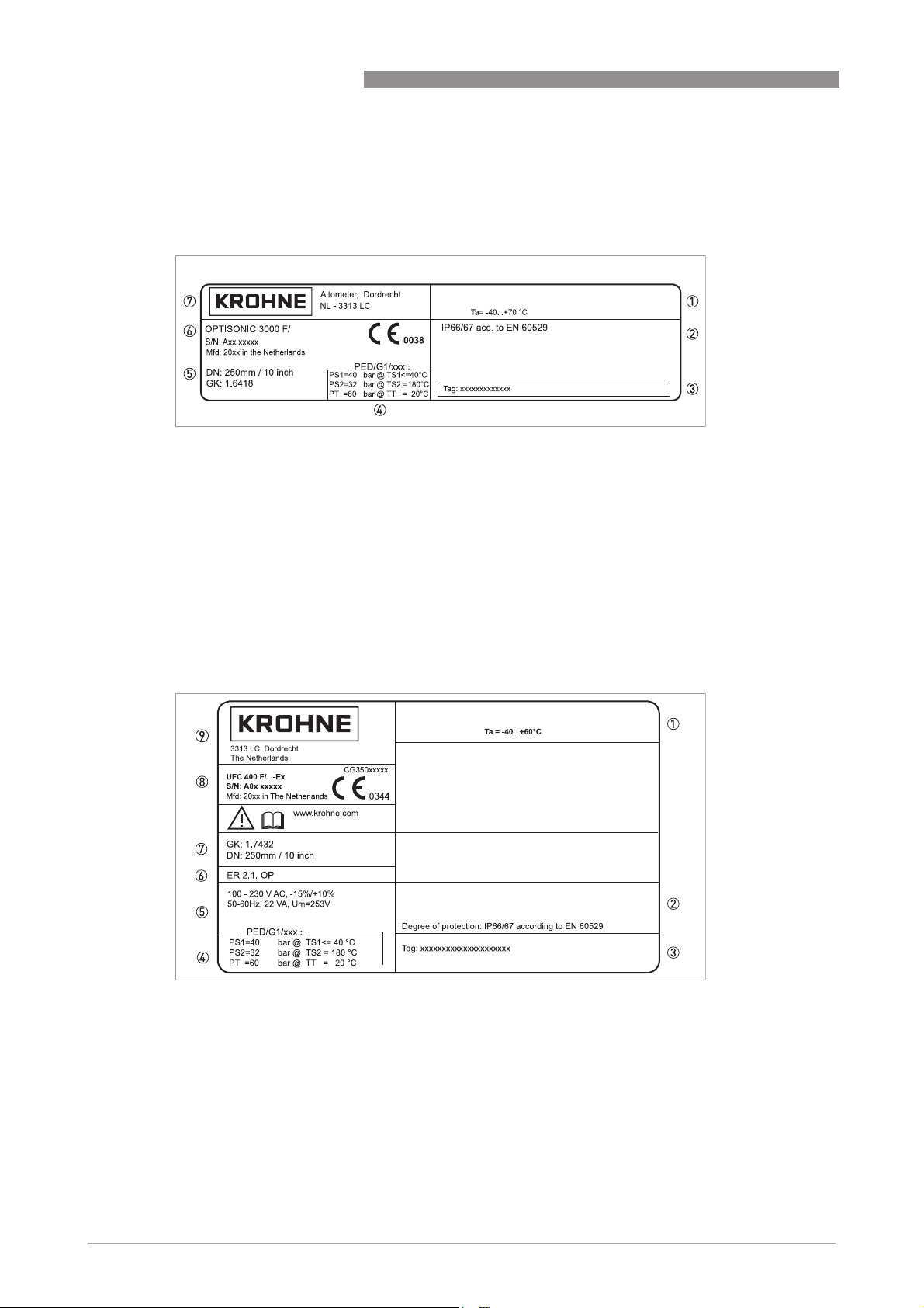
2.3.3 Examples of nameplates on the signal converter (field version)
Figure 2-4: Examples of nameplates on the signal converter (field version)
1 Ambient temperature
2 Protection class
3 Tag number
4 PED data, type I / II / II or SEP
5 Mains supply data
6 Electronics revision numbers
7 Calibration data
8 Type designation of the flowmeter and CE sign with number(s) of notified body / bodies
9 Name and address of the manufacturer
16
www.krohne.com 11/2013 - 4002037702 - HB OPTISONIC 3400 -en-R02
Page 17

OPTISONIC 3400
Electrical connection data of inputs/outputs (example of basic version)
Electrical connection data of inputs/outputs (example of basic version)
Electrical connection data of inputs/outputs (example of basic version)Electrical connection data of inputs/outputs (example of basic version)
1 Power supply (AC: L and N, DC: L+ and L-, PE for ≥ 24V AC, FE for ≤ 24 VAC and DC)
2 Connection data of connection terminal D/D-
3 Connection data of connection terminal C/C-
4 Connection data of connection terminal B/B-
5 Connection data of connection terminal A/A-, A+ only operable in basic version
DEVICE DESCRIPTION 2
• A = active mode; the signal converter supplies the power for connection of the subsequent
devices
• P = passive mode; external power supply required for operation of the subsequent devices
• N/C = connection terminals not connected
www.krohne.com11/2013 - 4002037702 - HB OPTISONIC 3400 -en-R02
17
Page 18

3 INSTALLATION
3.1 General notes on installation
INFORMATION!
Inspect the cartons carefully for damages or signs of rough handling. Report damage to the
carrier and to the local office of the manufacturer.
INFORMATION!
Do a check of the packing list to make sure that you have all the elements given in the order.
INFORMATION!
Look at the device nameplate to ensure that the device is delivered according to your order.
Check for the correct supply voltage printed on the nameplate.
3.2 Storage
• Store the device in a dry, dust-free location.
• Avoid continuous direct sunlight.
• Store the device in its original packaging.
• Storage temperature: -50...+70°C / -58...+158°F
OPTISONIC 3400
3.3 Transport
Signal converter
• Do not lift the signal converter by the cable glands.
Measuring sensor
• Do not lift the measuring sensor by the connection box.
• Use hoisting belts only.
• To transport flange devices, use lifting straps. Wrap these around both process connections.
18
Figure 3-1: Transport
www.krohne.com 11/2013 - 4002037702 - HB OPTISONIC 3400 -en-R02
Page 19
OPTISONIC 3400
3.4 Pre-installation requirements
INFORMATION!
To assure a quick, safe and uncomplicated installation, we kindly request you to make provisions
as stated below.
Make sure that you have all necessary tools available:
• Allen key (4 mm)
• Small screwdriver
• Wrench for cable glands
• Wrench for pipe mounting bracket (remote version only) see; on page 25
• Torque wrench for installing flowmeter in pipeline
3.5 General requirements
INFORMATION!
The following precautions must be taken to ensure reliable installation.
•
Make sure that there is adequate space to the sides.
•
Protect the signal converter from direct sunlight and install a sun shade if necessary.
•
Signal converters installed in control cabinets require adequate cooling, e.g. by fan or heat
exchanger.
•
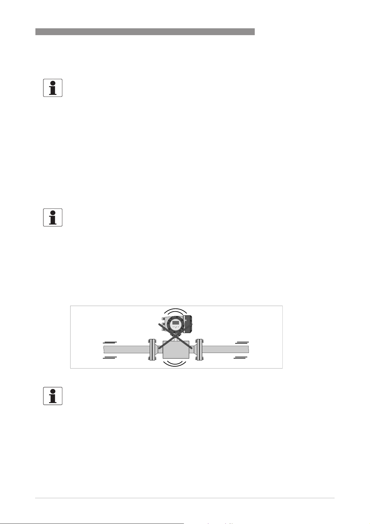
Do not expose the signal converter to intense vibration. The flowmeters are tested for a
vibration level in accordance with IEC 68-2-6.
INSTALLATION 3
3.5.1 Vibration
Figure 3-2: Avoid vibrations
INFORMATION!
In case of expected vibrations, please install a field version.
www.krohne.com11/2013 - 4002037702 - HB OPTISONIC 3400 -en-R02
19
Page 20
3 INSTALLATION
3.6 Installation conditions
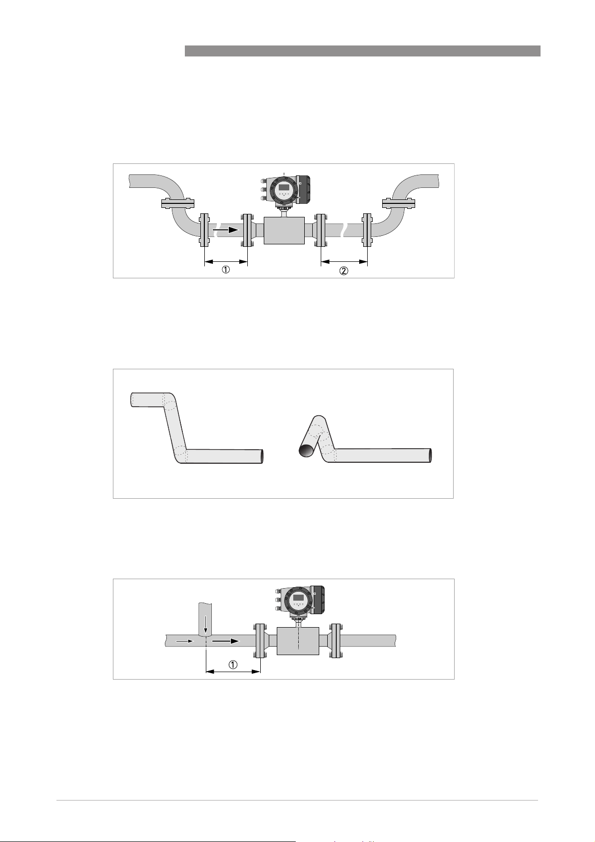
3.6.1 Inlet and outlet
Figure 3-3: Recommended inlet and oulet
1 Refer to chapter "Bends in 2 or 3 dimensions"
2 ≥ 3 DN
3.6.2 Bends in 2 or 3 dimensions
OPTISONIC 3400
Figure 3-4: 2 and 3 dimensional bends, in front of flowmeter
1 Bends in 2 dimensions: ≥ 5 DN; bends in 3 dimensions: ≥ 10 DN
3.6.3 T-section
Figure 3-5: Distance behind a T-section
1 ≥ 5 DN
20
www.krohne.com 11/2013 - 4002037702 - HB OPTISONIC 3400 -en-R02
Page 21
OPTISONIC 3400
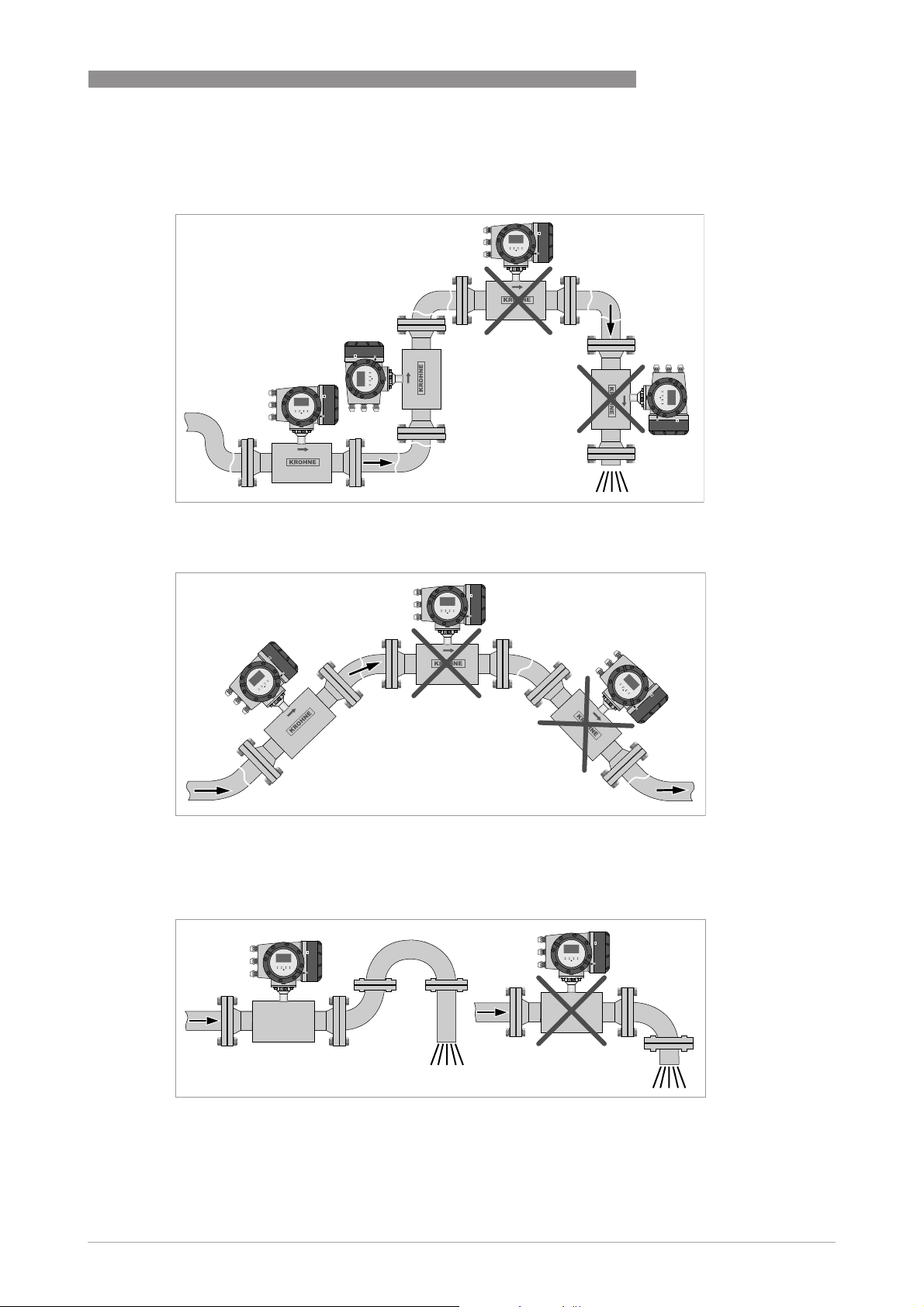
3.6.4 Bends
Figure 3-6: Installation in bending pipes
INSTALLATION 3
Figure 3-7: Installation in bending pipes
3.6.5 Open feed or discharge
Figure 3-8: Open discharge
Install meter on a lowered section of the pipe to ensure a full pipe condition through the meter.
www.krohne.com11/2013 - 4002037702 - HB OPTISONIC 3400 -en-R02
21
Page 22
3 INSTALLATION
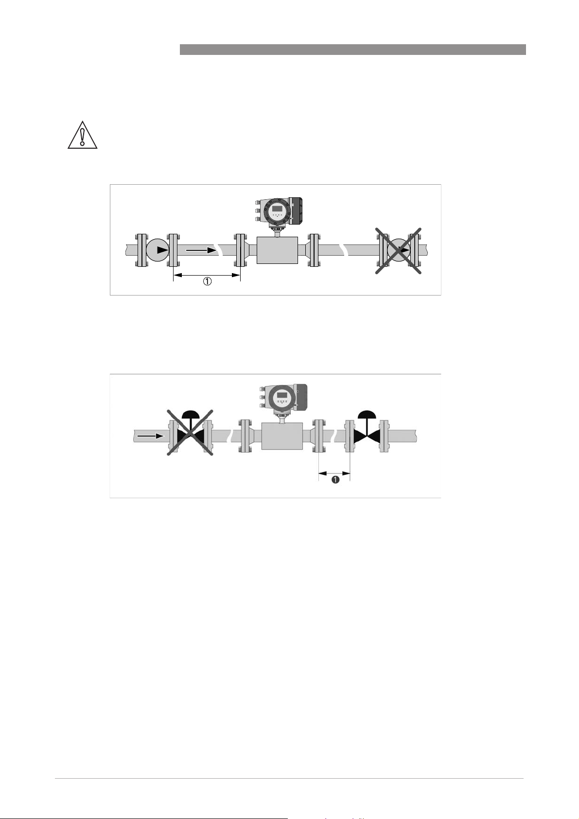
3.6.6 Position of pump
CAUTION!
Never install flowmeter at a pump suction side in order to avoid cavitation or flashing in the
flowmeter.
Figure 3-9: Position of pump
1 ≥ 15 DN
OPTISONIC 3400
3.6.7 Control valve
Figure 3-10: Installation in front of a control valve
1 ≥ 20 DN
22
www.krohne.com 11/2013 - 4002037702 - HB OPTISONIC 3400 -en-R02
Page 23
OPTISONIC 3400
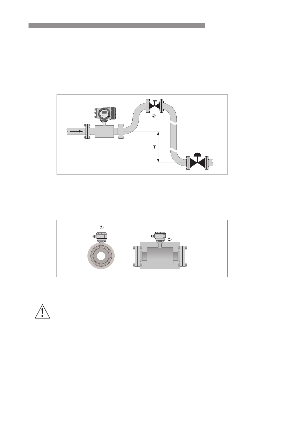
3.6.8 Down going pipeline over 5 m /16 ft length
Install air vent downstream of the flowmeter to prevent vacuum. Although this will not harm the
meter, it may cause gases to come out of solution (cavitate) and interfere with proper
measurements.
INSTALLATION 3
Figure 3-11: Down going pipeline over 5 m / 16 ft length
1 ≥ 5 m / 16 ft
2 Install air vent
3.6.9 Insulation
Figure 3-12: Insulation
1 Connection box
2 Insulation area
WARNING!
The flow sensor can be insulated completely, except for the connection box.
(Ex: maximum temperature, refer to Ex supplement)
For devices used in hazardous area, additional maximum temperature and insulation
precautions apply. Please refer to the Ex documentation!
www.krohne.com11/2013 - 4002037702 - HB OPTISONIC 3400 -en-R02
23
Page 24
3 INSTALLATION
3.7 Mounting
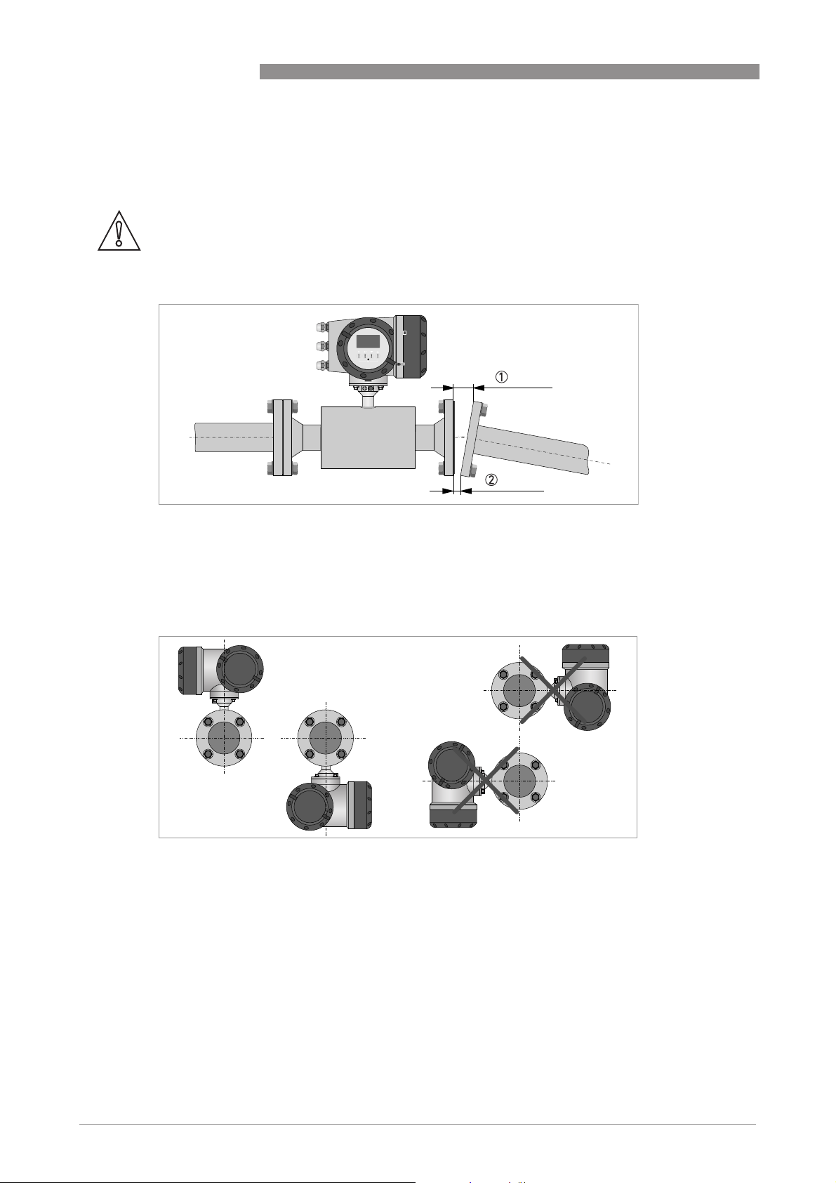
3.7.1 Flange deviation
CAUTION!
Max. permissible deviation of pipe flange faces:
- L
L
max
≤ 0.5 mm / 0.02"
min
OPTISONIC 3400
Figure 3-13: Flange deviation
1 L
max
2 L
min
3.7.2 Mounting position
Figure 3-14: Horizontal and vertical mounting
24
www.krohne.com 11/2013 - 4002037702 - HB OPTISONIC 3400 -en-R02
Page 25
OPTISONIC 3400
3.8 Mounting the field housing, remote version
INFORMATION!
Assembly materials and tools are not part of the delivery. Use the assembly materials and tools
in compliance with the applicable occupational health and safety directives.
3.8.1 Pipe mounting
Figure 3-15: Pipe mounting of the field housing
INSTALLATION 3
1 Fix the signal converter to the pipe.
2 Fasten the signal converter using standard U-bolts and washers.
3 Tighten the nuts.
www.krohne.com11/2013 - 4002037702 - HB OPTISONIC 3400 -en-R02
25
Page 26
3 INSTALLATION
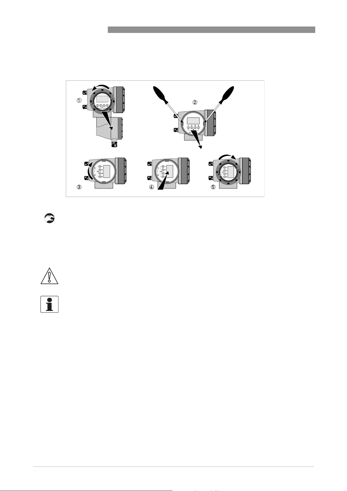
3.8.2 Turning the display of the field housing version
OPTISONIC 3400
Figure 3-16: Turning the display of the field housing version
The display of the field housing version can be turned in 90° increments.
1 Unscrew the cover from the display and operation control unit.
2 Using a suitable tool, pull out the two metal puller devices to the left and right of the display.
3 Pull out the display between the two metal puller devices and rotate it to the required position.
4 Slide the display and then the metal puller devices back into the housing.
5 Re-fit the cover and tighten it by hand.
CAUTION!
The ribbon cable of the display must not be folded or twisted repeatedly.
INFORMATION!
Each time a housing cover is opened, the thread should be cleaned and greased. Use only resinfree and acid-free grease.
Ensure that the housing gasket is properly fitted, clean and undamaged.
26
www.krohne.com 11/2013 - 4002037702 - HB OPTISONIC 3400 -en-R02
Page 27
OPTISONIC 3400
4.1 Safety instructions
DANGER!
All work on the electrical connections may only be carried out with the power disconnected. Take
note of the voltage data on the nameplate!
DANGER!
Observe the national regulations for electrical installations!
DANGER!
For devices used in hazardous areas, additional safety notes apply; please refer to the Ex
documentation.
WARNING!
Observe without fail the local occupational health and safety regulations. Any work done on the
electrical components of the measuring device may only be carried out by properly trained
specialists.
ELECTRICAL CONNECTIONS 4
INFORMATION!
Look at the device nameplate to ensure that the device is delivered according to your order.
Check for the correct supply voltage printed on the nameplate.
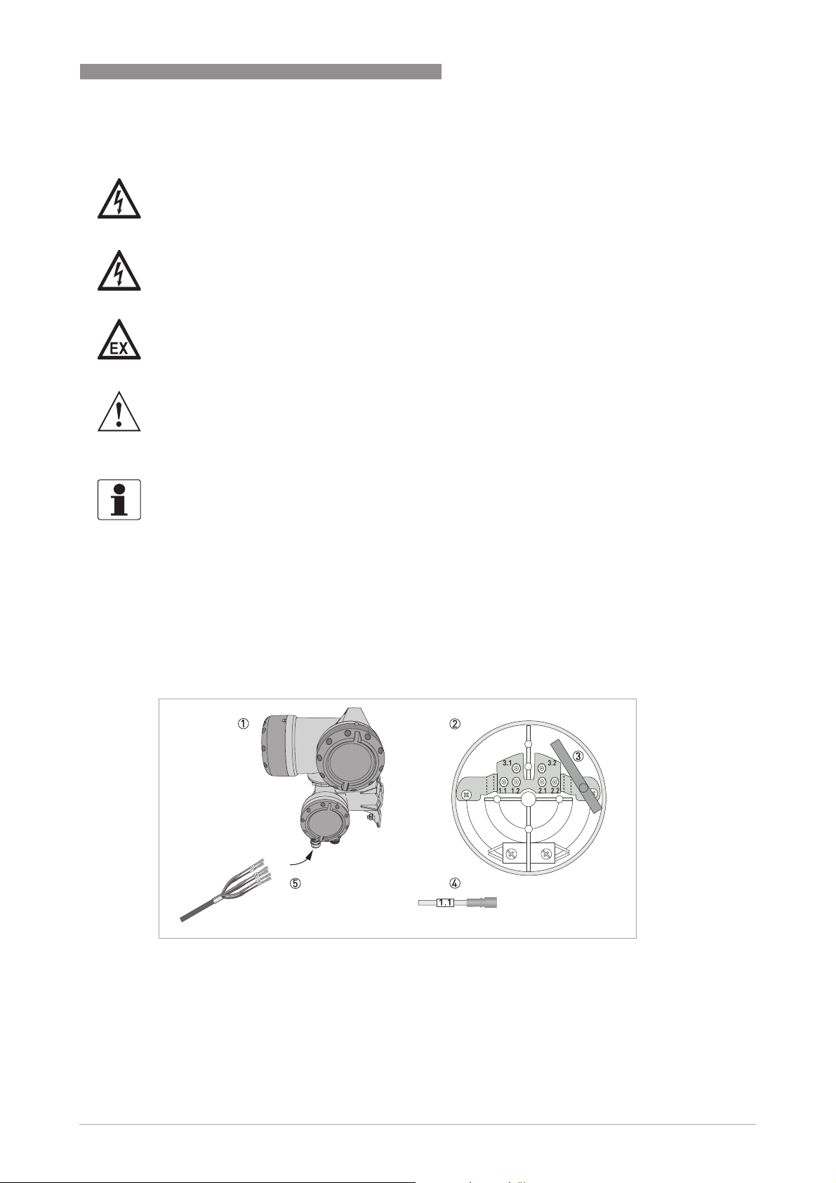
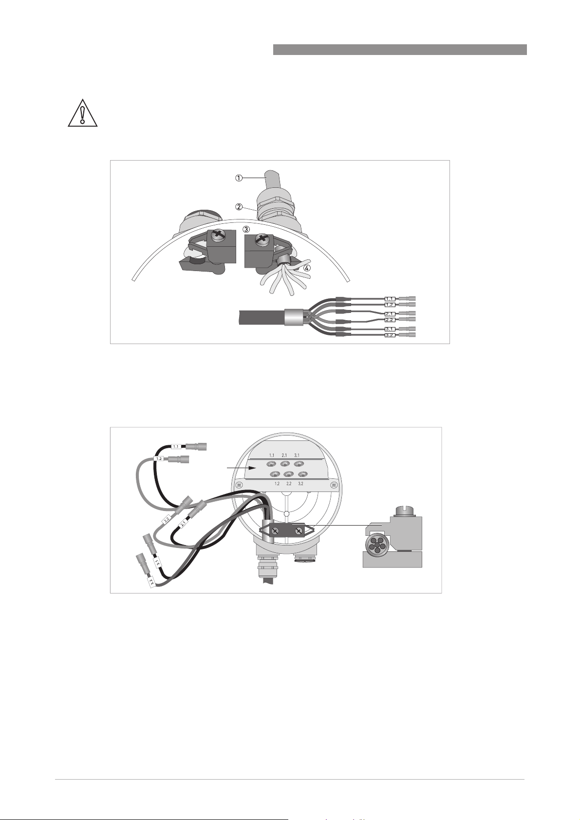
4.2 Signal cable (remote versions only)
The flow sensor is connected to the signal converter via one signal cable, with 6 (labeled) inner
coax cables for the connection of three acoustic paths.
Figure 4-1: Construction of field version
1 Signal converter
2 Open connection box
3 Tool for releasing connectors
4 Marking on cable
5 Insert cable(s) into terminal compartment
www.krohne.com11/2013 - 4002037702 - HB OPTISONIC 3400 -en-R02
27
Page 28
4 ELECTRICAL CONNECTIONS
CAUTION!
To ensure smooth functioning, always use the signal cable(s) included in the delivery.
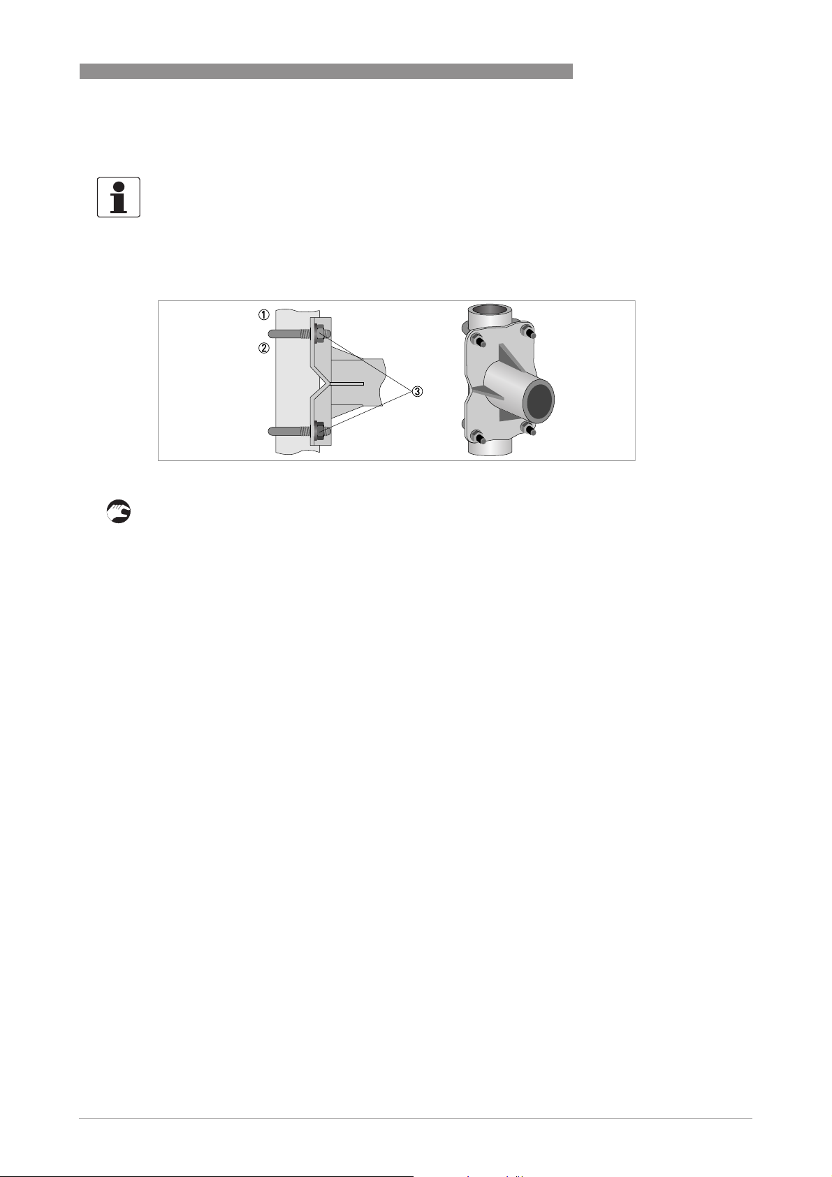
OPTISONIC 3400
Figure 4-2: Clamp the cables on the shielding bush
1 Cables
2 Cable glands
3 Grounding clamps
4 Cable with metal shielding bush
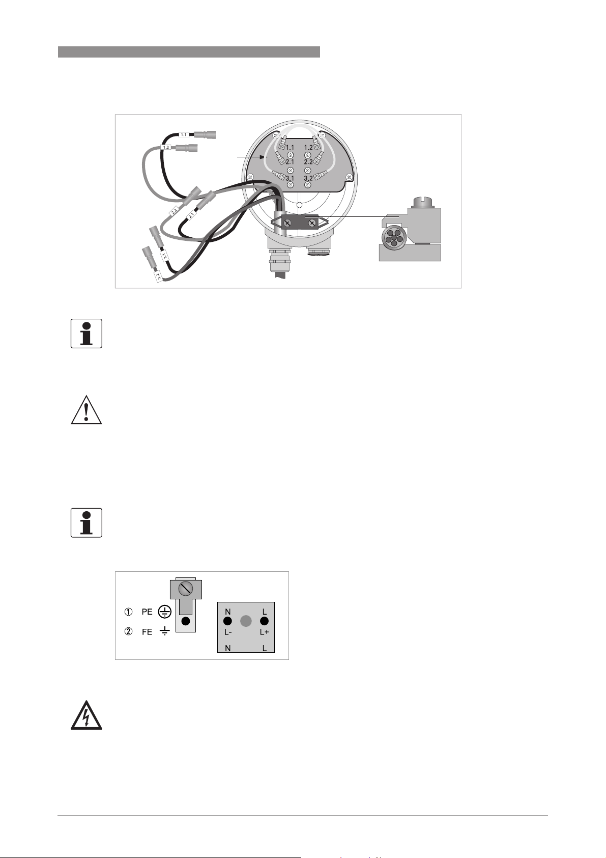
Electrical connection - Standard version
Figure 4-3: Connect the cables in the connection box of the flow sensor
28
www.krohne.com 11/2013 - 4002037702 - HB OPTISONIC 3400 -en-R02
Page 29
OPTISONIC 3400
Connection of flow sensor type Cryogenic and XXT
Figure 4-4: Connect the cables in the connection box of the flow sensor
INFORMATION!
Connect the cable on connector with similar numeral marking
ELECTRICAL CONNECTIONS 4
4.3 Power supply
WARNING!
When this device is intended for permanent connection to the mains.
It is required (for example for service) to mount an external switch or circuit breaker near the
device for disconnection from the mains. It shall be easily reachable by the operator and marked
as the disconnecting the device for this equipment.
The switch or circuit breaker and wiring has to be suitable for the application and shall also be in
accordance with the local (safety) requirements of the (building) installation
(e.g. IEC 60947-1 / -3)
INFORMATION!
The power terminals in the terminal compartments are equipped with additional hinged lids to
prevent accidental contact.
1 100...230 VAC (-15% / +10%), 22 VA
2 24 VAC/DC (AC: -15% / +10%; DC: -25% / +30%), 22 VA or 12 W
DANGER!
The device must be grounded in accordance with regulations in order to protect personnel
against electric shocks.
www.krohne.com11/2013 - 4002037702 - HB OPTISONIC 3400 -en-R02
29
Page 30
4 ELECTRICAL CONNECTIONS
100…230 VAC
• Connect the protective ground conductor PE of the mains power supply to the separate
terminal in the terminal compartment of the signal converter.
• Connect the live conductor to the L terminal and the neutral conductor to the N terminal.
24 VAC/DC
• Connect a functional ground FE to the separate U-clamp terminal in the terminal
compartment of the signal converter.
• When connecting to functional extra-low voltages, provide a facility for protective separation
(PELV) (VDE 0100 / VDE 0106 and/or IEC 364 / IEC 536 or relevant national regulations).
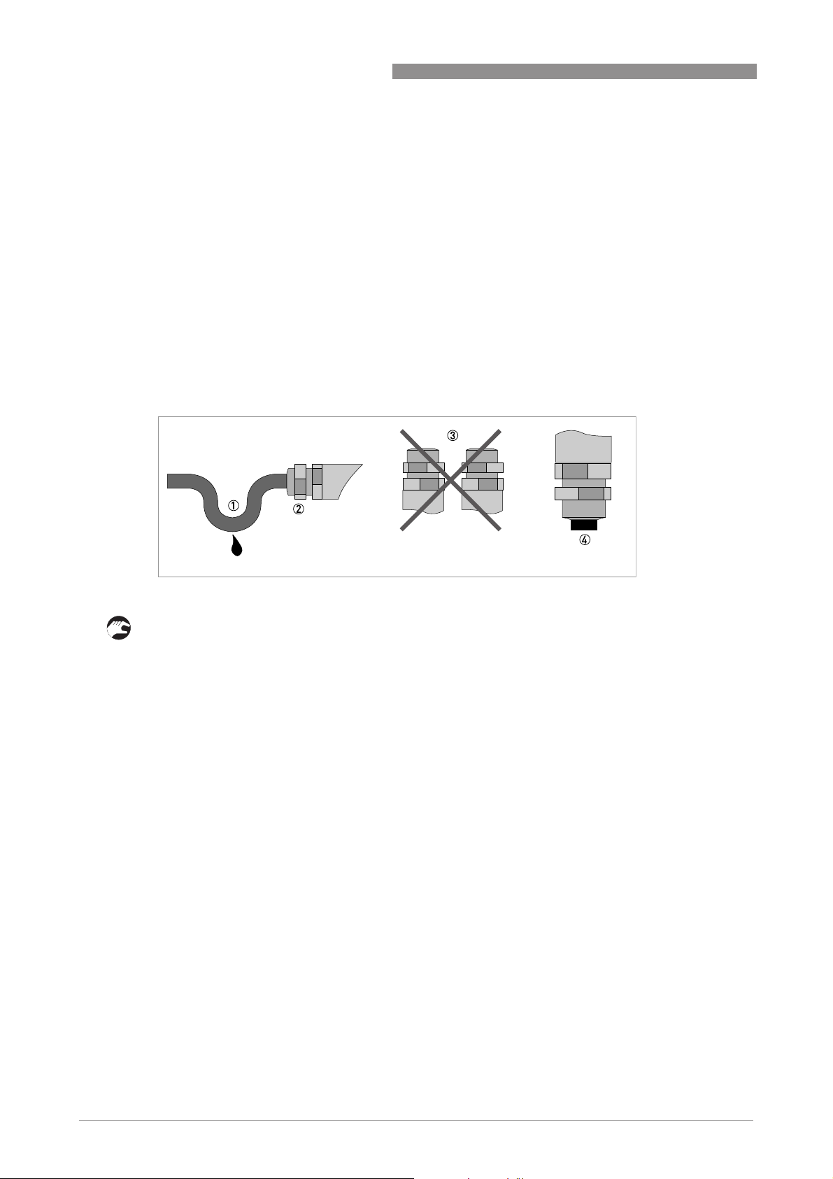
4.4 Laying electrical cables correctly
OPTISONIC 3400
Figure 4-5: Protect housing from dust and water
1 Lay the cable in a loop just before the housing.
2 Tighten the screw connection of the cable entry securely.
3 Never mount the housing with the cable entries facing upwards.
4 Seal cable entries that are not needed with a plug.
30
www.krohne.com 11/2013 - 4002037702 - HB OPTISONIC 3400 -en-R02
Page 31

OPTISONIC 3400
4.5 Inputs and outputs, overview
4.5.1 Combinations of the inputs/outputs (I/Os)
This signal converter is available with various input/output combinations.
Basic version
• Has 1 current output, 1 pulse output and 2 status outputs / limit switches.
• The pulse output can be set as status output/limit switch and one of the status outputs as a
control input.
Ex i version
• Depending on the task, the device can be configured with various output modules.
• Current outputs can be active or passive.
• Optionally available also with Foundation Fieldbus and Profibus PA
Modular version
• Depending on the task, the device can be configured with various output modules.
ELECTRICAL CONNECTIONS 4
Bus systems
• The device allows intrinsically safe and non intrinsically safe bus interfaces in combination
with additional modules.
• For connection and operation of bus systems, please note the separate documentation.
Ex option
• For hazardous areas, all of the input/output variants for the housing designs C and F with
terminal compartment in the Ex d (pressure-resistant casing) or Ex e (increased safety)
versions can be delivered.
• Please refer to the separate instructions for connection and operation of the Ex-devices.
www.krohne.com11/2013 - 4002037702 - HB OPTISONIC 3400 -en-R02
31
Page 32

4 ELECTRICAL CONNECTIONS
4.5.2 Description of the CG number
Figure 4-6: Marking (CG number) of the electronics module and input/output variants
1 ID number:5
2 ID number: 0 = standard
3 Power supply option
4 Display (language versions)
5 Input/output version (I/O)
6 1st optional module for connection terminal A
7 2nd optional module for connection terminal B
The last 3 digits of the CG number (5, 6 and 7) indicate the assignment of the terminal
connections. Please refer to the following examples.
Examples for CG number
OPTISONIC 3400
CG 350 11 100 100...230 VAC & standard display; basic I/O: Ia or Ip & Sp/Cp & Sp & Pp/S
p
CG 350 11 7FK 100...230 VAC & standard display; modular I/O: Ia & PN/SN and optional module PN/SN & C
CG 350 81 4EB 24 VDC & standard display; modular I/O: Ia & Pa/Sa and optional module Pp/Sp & I
p
Description of abbreviations and CG identifier for possible optional modules
on terminals A and B
Abbreviation Identifier for CG No. Description
I
a
I
p
Pa / S
a
Pp / S
p
PN / S
N
C
a
C
p
C
N
- 8 No additional module installed
- 0 No further module possible
A Active current output
B Passive current output
C Active pulse output, frequency output, status output or limit switch
(changeable)
E Passive pulse output, frequency output, status output or limit switch
(changeable)
F Passive pulse output, frequency output, status output or limit switch acc.
to NAMUR (changeable)
G Active control input
K Passive control input
H Active control input to NAMUR
Signal converter monitors cable breaks and short circuits acc. to
EN 60947-5-6. Errors indicated on LC display. Error messages possible
via status output.
N
32
www.krohne.com 11/2013 - 4002037702 - HB OPTISONIC 3400 -en-R02
Page 33

OPTISONIC 3400
4.5.3 Fixed, non-alterable input/output versions
This signal converter is available with various input/output combinations.
• The grey boxes in the tables denote unassigned or unused connection terminals.
• In the table, only the final digits of the CG no. are depicted.
• Connection terminal A+ is only operable in the basic input/output version.
CG-No. Connection terminals
A+ A A- B B- C C- D D-
Basic in-/output (I/O) (Standard)
1 0 0
Ia + HART® active 1
Ip + HART® passive 1
Ex-i in-/outputs (Option)
2 0 0
3 0 0
2 1 0 Ia active PN / SNNAMUR
3 1 0 Ia active PN / SNNAMUR
2 2 0 Ip passive PN / SNNAMUR
3 2 0 Ip passive PN / SNNAMUR
1 Function changed by reconnecting
2 Changeable
Sp / Cp passive 2 Sp passive Pp / Sp passive 2
passive 2
C
p
passive 2
C
p
Cp passive 2
passive 2
C
p
ELECTRICAL CONNECTIONS 4
Ia + HART® active
Ip + HART® passive
Ia + HART® active
Ip + HART® passive
Ia + HART® active
Ip + HART® passive
PN / SN NAMUR 2
PN / SN NAMUR 2
PN / SN NAMUR 2
PN / SN NAMUR 2
PN / SNNAMUR 2
PN / SNNAMUR 2
www.krohne.com11/2013 - 4002037702 - HB OPTISONIC 3400 -en-R02
33
Page 34

4 ELECTRICAL CONNECTIONS
4.5.4 Alterable input/output versions
This signal converter is available with various input/output combinations.
• The grey boxes in the tables denote unassigned or unused connection terminals.
• In the table, only the final digits of the CG no. are depicted.
• Term. = (connection) terminal
CG no. Connection terminals
A+ A A- B B- C C- D D-
Modular IOs (option)
4 _ _ max. 2 optional modules for term. A + B
8 _ _ max. 2 optional modules for term. A + B
6 _ _ max. 2 optional modules for term. A + B
B _ _ max. 2 optional modules for term. A + B
7 _ _ max. 2 optional modules for term. A + B
C _ _ max. 2 optional modules for term. A + B
Ia + HART® active
Ip + HART® passive
Ia + HART® active
Ip + HART® passive
Ia + HART® active
Ip + HART® passive
OPTISONIC 3400
Pa / Sa active 1
Pa / Sa active 1
Pp / Sp passive 1
Pp / Sp passive 1
PN / SN NAMUR 1
PN / SN NAMUR 1
PROFIBUS PA
D _ _ max. 2 optional modules for term. A + B PA+ (2) PA- (2) PA+ (1) PA- (1)
FOUNDATION Fieldbus (option)
E _ _ max. 2 optional modules for term. A + B V/D+ (2) V/D- (2) V/D+ (1) V/D- (1)
Modbus (option)
G _ _ 2 max. 2 optional modules for term. A + B CommonSign. B
(D1)
1 changeable
2 not activated bus terminator
Sign. A
(D0)
34
www.krohne.com 11/2013 - 4002037702 - HB OPTISONIC 3400 -en-R02
Page 35

OPTISONIC 3400
4.6 Description of the inputs and outputs
4.6.1 Control input
INFORMATION!
Depending on the version, the control inputs must be connected passively or actively or
according to NAMUR EN 60947-5-6! Which I/O version and inputs/outputs are installed in your
signal converter are indicated on the sticker in the cover of the terminal compartment.
• All control inputs are electrically isolated from each other and from all other circuits.
• All operating data and functions can be adjusted.
• Passive mode: external power supply required:
≤ 32 VDC
U
ext
• Active mode: use of the internal power supply:
=24VDC
U
nom
• NAMUR mode: in accordance with EN 60947-5-6
(Active control input to NAMUR EN 60947-5-6: signal converter monitors cable breaks and
short circuits acc. to EN 60947-5-6. Errors indicated on LC display. Error messages possible
via status output.
• For information on the adjustable operating states refer to
ELECTRICAL CONNECTIONS 4
Function tables
on page 63
DANGER!
For devices used in hazardous areas, additional safety notes apply; please refer to the Ex
documentation.
www.krohne.com11/2013 - 4002037702 - HB OPTISONIC 3400 -en-R02
35
Page 36

4 ELECTRICAL CONNECTIONS
4.6.2 Current output
INFORMATION!
The current outputs must be connected depending on the version! Which I/O versions and
inputs/outputs are installed in your signal converter are indicated on the sticker in the cover of
the terminal compartment.
• All outputs are electrically isolated from each other and from all other circuits.
• All operating data and functions can be adjusted.
• Passive mode: external power U
• Active mode: load impedance R
≤ 450 Ω at I ≤ 22 mA for Ex i outputs
R
L
• Self-monitoring: interruption or load impedance too high in the current output loop
• Error message possible via status output, error indication on LC display.
• Current value error detection can be adjusted.
• Automatic range conversion via threshold or control input. The setting range for the
threshold is between 5 and 80% of Q
smaller to larger range of 1:20 to 1:1.25).
Signaling of the active range possible via a status output (adjustable).
• Forward / reverse flow measurement (F/R mode) is possible.
ext
L
≤ 32 VDC at I ≤ 22 mA
≤ 1kΩ at I ≤ 22 mA;
, ± 0...5% hysteresis (corresponding ratio from
100%
OPTISONIC 3400
INFORMATION!
For further information refer to Connection diagrams of inputs and outputs on page 39
.
DANGER!
For devices used in hazardous areas, additional safety notes apply; please refer to the Ex
documentation.
36
www.krohne.com 11/2013 - 4002037702 - HB OPTISONIC 3400 -en-R02
Page 37

OPTISONIC 3400
4.6.3 Pulse and frequency output
INFORMATION!
Depending on the version, the pulse and frequency outputs must be connected passively or
actively or according to NAMUR EN 60947-5-6! Which I/O version and inputs/outputs are
installed in your signal converter are indicated on the sticker in the cover of the terminal
compartment.
• All outputs are electrically isolated from each other and from all other circuits.
• All operating data and functions can be adjusted.
• Passive mode:
External power supply required: U
I ≤ 20 mA at f ≤ 10 kHz (override up to f
I ≤ 100 mA at f ≤ 100 Hz
• Active mode:
Use of the internal power supply: U
I ≤ 20 mA at f ≤ 10 kHz (over range up to f
I ≤ 20 mA at f ≤ 100 Hz
• NAMUR mode: passive in accordance with EN 60947-5-6, f ≤ 10 kHz,
over range up to f
• Scaling:
Frequency output: in pulses per time unit (e.g. 1000 pulses/s at Q
Pulse output: quantity per pulse.
• Pulse width:
symmetric (pulse duty factor 1:1, independent of output frequency)
automatic (with fixed pulse width, duty factor approx. 1:1 at Q
fixed (pulse width adjustable as required from 0.05 ms...2 s)
• Forward / reverse flow measurement (F/R mode) is possible.
• All pulse and frequency outputs can also be used as a status output / limit switch.
max
≤ 12 kHz
≤ 32 VDC
ext
max
=24VDC
nom
ELECTRICAL CONNECTIONS 4
≤ 12 kHz)
≤ 12 kHz)
max
);
100%
) or
100%
INFORMATION!
For further information refer to Connection diagrams of inputs and outputs on page 39
.
DANGER!
For devices used in hazardous areas, additional safety notes apply; please refer to the Ex
documentation.
www.krohne.com11/2013 - 4002037702 - HB OPTISONIC 3400 -en-R02
37
Page 38

4 ELECTRICAL CONNECTIONS
4.6.4 Status output and limit switch
INFORMATION!
Depending on the version, the status outputs and limit switches must be connected passively or
actively or according to NAMUR EN 60947-5-6! Which I/O version and inputs/outputs are
installed in your signal converter are indicated on the sticker in the cover of the terminal
compartment.
• The status outputs / limit switches are electrically isolated from each other and from all
other circuits.
• The output stages of the status outputs/limit switches during simple active or passive
operation behave like relay contacts and can be connected with any polarity.
• All operating data and functions can be adjusted.
• Passive mode: external power supply required:
≤ 32 VDC; I ≤ 100 mA
U
ext
• Active mode: use of the internal power supply:
=24VDC; I ≤ 20 mA
U
nom
• NAMUR mode: passive in accordance with EN 60947-5-6
• For information on the adjustable operating states refer to
Function tables
OPTISONIC 3400
on page 63.
INFORMATION!
For further information refer to Connection diagrams of inputs and outputs on page 39
.
DANGER!
For devices used in hazardous areas, additional safety notes apply; please refer to the Ex
documentation.
38
www.krohne.com 11/2013 - 4002037702 - HB OPTISONIC 3400 -en-R02
Page 39

OPTISONIC 3400
ELECTRICAL CONNECTIONS 4
4.7 Connection diagrams of inputs and outputs
4.7.1 Important notes
INFORMATION!
Depending on the version, the inputs/outputs must be connected passively or actively or acc. to
NAMUR EN 60947-5-6! Which I/O version and inputs/outputs are installed in your signal
converter are indicated on the sticker in the cover of the terminal compartment.
• All groups are electrically isolated from each other and from all other input and output
circuits.
• Passive mode: An external power supply is necessary to operate (activation) the subsequent
devices (U
• Active mode: The signal converter supplies the power for operation (activation) of the
subsequent devices, observe max. operating data.
• Terminals that are not used should not have any conductive connection to other electrically
conductive parts.
DANGER!
For devices used in hazardous areas, additional safety notes apply; please refer to the Ex
documentation.
ext
).
Description of the used abbreviations
I
I
a
P
a
P
N
S
a
S
N
C
a
C
N
Current output active or passive
p
P
Pulse/frequency output active or passive
p
Pulse/frequency output passive acc. to NAMUR EN 60947-5-6
S
Status output/limit switch active or passive
p
Status output/limit switch passive acc. to NAMUR EN 60947-5-6
C
Control input active or passive
p
Control input active acc. to NAMUR EN 60947-5-6:
Signal converter monitors cable breaks and short circuits acc. to EN 60947-5-6. Errors
indicated on LC display. Error messages possible via status output.
www.krohne.com11/2013 - 4002037702 - HB OPTISONIC 3400 -en-R02
39
Page 40

4 ELECTRICAL CONNECTIONS
4.7.2 Description of the electrical symbols
mA meter
0...20 mA or 4...20 mA and other
RL is the internal resistance of the measuring point including the cable
resistance
DC voltage source (U
OPTISONIC 3400
), external power supply, any connection polarity
ext
Table 4-1: Description of symbols
DC voltage source (U
connection diagrams
Internal DC voltage source
Controlled internal power source in the device
Electronic or electromagnetic counter
At frequencies above 100 Hz, shielded cables must be used to connect the
counters.
Ri Internal resistance of the counter
Button, NO contact or similar
), observe connection polarity according to
ext
40
www.krohne.com 11/2013 - 4002037702 - HB OPTISONIC 3400 -en-R02
Page 41

OPTISONIC 3400
4.7.3 Basic inputs/outputs
CAUTION!
Observe connection polarity.
INFORMATION!
For further information refer to Description of the inputs and outputs on page 35
HART® connection on page 53
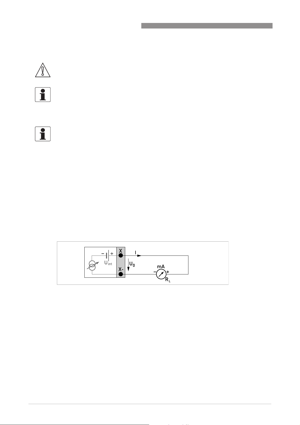
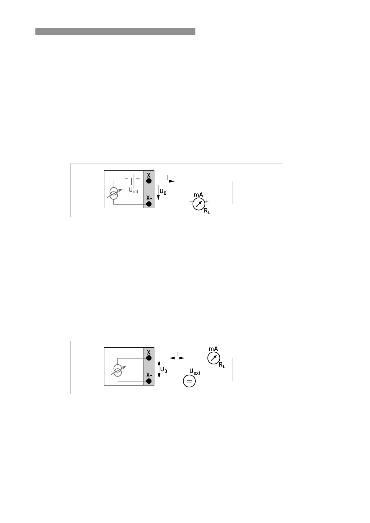
Current output active (HART®), basic I/Os
• U
• I ≤ 22 mA
• R
= 24 VDC nominal
int, nom
≤ 1kΩ
L
ELECTRICAL CONNECTIONS 4
and refer to
.
Figure 4-7: Current output active I
a
Current output passive (HART®), basic I/Os
• U
• U
• I ≤ 22 mA
• U
• R
Figure 4-8: Current output passive I
= 24 VDC nominal
int, nom
≤ 32 VDC
ext
≥ 1.8 V
0
≤ (U
L
ext-U0
)/I
max
p
www.krohne.com11/2013 - 4002037702 - HB OPTISONIC 3400 -en-R02
41
Page 42

4 ELECTRICAL CONNECTIONS
INFORMATION!
•
For frequencies above 100 Hz, shielded cables are to be used in order to reduce effects from
electrical interferences (EMC).
•
Compact and field housing versions:
Compact and field housing versions: Shield connected via the cable terminals in the terminal
Compact and field housing versions:Compact and field housing versions:
compartment.
•
Any connection polarity.
Pulse/frequency output passive, basic I/Os
• U
• f
• f
• If the following maximum load resistance R
• The minimum load resistance R
• Can also be set as status output; for the electrical connection refer to status output
≤ 32 VDC
ext
in operating menu set to f
max
max
I ≤ 100 mA
open:
I ≤ 0.05 mA at U
= 32 VDC
ext
closed:
U
U
= 0.2 V at I ≤ 10 mA
0, max
= 2 V at I ≤ 100 mA
0, max
in the operating menu set to 100 Hz < f
max
I ≤ 20 mA
open:
I ≤ 0.05 mA at U
= 32 VDC
ext
closed:
U
U
U
= 1.5 V at I ≤ 1 mA
0, max
= 2.5 V at I ≤ 10 mA
0, max
= 5.0 V at I ≤ 20 mA
0, max
reduced accordingly by parallel connection of R:
f ≤ 100 Hz: R
f ≤ 1 kHz: R
f ≤ 10 kHz: R
R
L, min
=(U
ext-U0
L, max
L, max
L, max
= 47 kΩ
= 10 kΩ
= 1 kΩ
)/I
max
L, min
connection diagram.
≤ 100 Hz:
≤ 10 kHz:
max
is exceeded, the load resistance RL must be
L, max
is calculated as follows:
OPTISONIC 3400
42
Figure 4-9: Pulse/frequency output passive P
p
www.krohne.com 11/2013 - 4002037702 - HB OPTISONIC 3400 -en-R02
Page 43

OPTISONIC 3400
INFORMATION!
•
Any connection polarity.
Status output / limit switch passive, basic I/Os
• U
• I ≤ 100 mA
• R
R
• open:
I ≤ 0.05 mA at U
closed:
U
U
• The output is open when the device is de-energized.
• X stands for the terminals B, C or D. The functions of the connection terminals depend on the
settings.
≤ 32 VDC
ext
= 47 kΩ
L, max
=(U
L, min
0, max
0, max
ext-U0
= 0.2 V at I ≤ 10 mA
= 2 V at I ≤ 100 mA
)/I
= 32 VDC
ext
ELECTRICAL CONNECTIONS 4
max
Figure 4-10: Status output / limit switch passive S
p
Control input passive, basic I/Os
• 8V≤ U
• I
max
I
max
• Switching point for identifying "contact open or closed":
Contact open (off): U
Contact closed (on): U
• Can also be set as a status output; for the electrical connection refer to status output
connection diagram.
Figure 4-11: Control input passive C
1 Signal
≤ 32 VDC
ext
= 6.5 mA at U
= 8.2 mA at U
≤ 24 VDC
ext
≤ 32 VDC
ext
≤ 2.5 V with I
0
≥ 8 V with I
0
= 0.4 mA
nom
= 2.8 mA
nom
p
www.krohne.com11/2013 - 4002037702 - HB OPTISONIC 3400 -en-R02
43
Page 44
4 ELECTRICAL CONNECTIONS
4.7.4 Modular inputs/outputs and bus systems
CAUTION!
Observe connection polarity.
INFORMATION!
•
For further information on electrical connection refer to Description of the inputs and outputs
on page 35
For the electrical connection of bus systems, please refer to the separate documentation for
•
the respective bus systems.
INFORMATION!
•
For frequencies above 100 Hz, shielded cables are to be used in order to reduce effects from
electrical interferences (EMC).
•
Compact and field housing versions:
Compact and field housing versions: Shield connected via the cable terminals in the terminal
Compact and field housing versions:Compact and field housing versions:
compartment.
•
Any connection polarity.
.
OPTISONIC 3400
Current output active (only current output terminals C/C- have HART® capability),
modular I/Os
• U
• I ≤ 22 mA
• R
• X designates the connection terminals A, B or C, depending on the version of the signal
converter.
Figure 4-12: Current output active I
int, nom
≤ 1kΩ
L
= 24 VDC
a
Current output passive (only current output terminals C/C- have HART® capability),
modular I/Os
• U
• I ≤ 22 mA
• U
• R
• X designates the connection terminals A, B or C, depending on the version of the signal
≤ 32 VDC
ext
≥ 1.8 V
0
= (U
L, max
converter.
- U0) / I
ext
max
44
www.krohne.com 11/2013 - 4002037702 - HB OPTISONIC 3400 -en-R02
Page 45

OPTISONIC 3400
ELECTRICAL CONNECTIONS 4
Figure 4-13: Current output passive I
p
Pulse/frequency output active, modular I/Os
• U
• f
• f
• If the following maximum load impedance R
• The minimum load impedance R
• X designates the connection terminals A, B or D, depending on the version of the signal
= 24 VDC
nom
in the operating menu set to f
max
≤ 100 Hz:
max
I ≤ 20 mA
open:
I ≤ 0.05 mA
closed:
U
= 24 V at I = 20 mA
0, nom
in operating menu set to 100 Hz < f
max
≤ 10 kHz:
max
I ≤ 20 mA
open:
I ≤ 0.05 mA
closed:
U
U
U
= 22.5 V at I = 1 mA
0, nom
= 21.5 V at I = 10 mA
0, nom
=19V at I=20mA
0, nom
L, max
be reduced accordingly by parallel connection of R:
f ≤ 100 Hz: R
f ≤ 1 kHz: R
f ≤ 10 kHz: R
L, min
=(U
R
ext-U0
L, max
L, max
L, max
= 47 kΩ
= 10 kΩ
=1kΩ
)/I
max
is calculated as follows:
L, min
converter.
is exceeded, the load impedance RL must
Figure 4-14: Pulse / frequency output active P
www.krohne.com11/2013 - 4002037702 - HB OPTISONIC 3400 -en-R02
a
45
Page 46

4 ELECTRICAL CONNECTIONS
Pulse/frequency output passive, modular I/Os
• U
• f
• f
• If the following maximum load impedance R
• The minimum load impedance R
• Can also be set as status output; refer to status output connection diagram.
• X designates the connection terminals A, B or D, depending on the version of the signal
≤ 32 VDC
ext
in the operating menu set to f
max
I ≤ 100 mA
open:
I ≤ 0.05 mA at U
= 32 VDC
ext
closed:
U
U
=0.2V at I≤ 10 mA
0, max
=2V at I≤ 100 mA
0, max
in operating menu set to 100 Hz < f
max
open:
I ≤ 0.05 mA at U
= 32 VDC
ext
closed:
U
U
U
=1.5V at I≤ 1mA
0, max
=2.5 V at I ≤ 10 mA
0, max
=5V at I≤ 20 mA
0, max
be reduced accordingly by parallel connection of R:
f ≤ 100 Hz: R
f ≤ 1 kHz: R
f ≤ 10 kHz: R
R
L, min
=(U
ext-U0
L, max
L, max
L, max
= 47 kΩ
= 10 kΩ
=1kΩ
)/I
max
L, min
converter.
≤ 100 Hz:
max
≤ 10 kHz:
max
is exceeded, the load impedance RL must
L, max
is calculated as follows:
OPTISONIC 3400
46
Figure 4-15: Pulse frequency output passive P
www.krohne.com 11/2013 - 4002037702 - HB OPTISONIC 3400 -en-R02
p
Page 47

OPTISONIC 3400
Pulse and frequency output passive PN NAMUR, modular I/O
• Connection in conformity with EN 60947-5-6
• open:
I
closed:
I
• X designates the connection terminals A, B or D, depending on the version of the signal
converter.
= 0.6 mA
nom
= 3.8 mA
nom
ELECTRICAL CONNECTIONS 4
Figure 4-16: Pulse and frequency output passive PN to NAMUR EN 60947-5-6
Status output / limit switch active, modular I/Os
• Observe connection polarity.
• U
• I ≤ 20 mA
• R
• open:
• X designates the connection terminals A, B or D, depending on the version of the signal
=24VDC
int
≤ 47 kΩ
L
I ≤ 0.05 mA
closed:
U
= 24 V at I = 20 mA
0, nom
converter.
Figure 4-17: Status output / limit switch active S
www.krohne.com11/2013 - 4002037702 - HB OPTISONIC 3400 -en-R02
a
47
Page 48

4 ELECTRICAL CONNECTIONS
Status output / limit switch passive, modular I/Os
• Any connection polarity.
• U
• I ≤ 100 mA
• R
• open:
• The output is open when the device is de-energized.
• X designates the connection terminals A, B or D, depending on the version of the signal
=32VDC
ext
= 47 kΩ
L, max
L, min
=(U
ext-U0
R
I ≤ 0.05 mA at U
closed:
U
U
=0.2V at I≤ 10 mA
0, max
=2V at I≤ 100 mA
0, max
converter.
)/I
= 32 VDC
ext
max
OPTISONIC 3400
Figure 4-18: Status output / limit switch passive S
p
Status output / limit switch SN NAMUR, modular I/Os
• Any connection polarity.
• Connection in conformity with EN 60947-5-6
• open:
= 0.6 mA
I
nom
closed:
= 3.8 mA
I
nom
• The output is open when the device is de-energized.
• X designates the connection terminals A, B or D, depending on the version of the signal
converter.
48
Figure 4-19: Status output / limit switch SN to NAMUR EN 60947-5-6
www.krohne.com 11/2013 - 4002037702 - HB OPTISONIC 3400 -en-R02
Page 49

OPTISONIC 3400
CAUTION!
Observe connection polarity.
Control input active, modular I/Os
• U
• External contact open:
U
External contact closed:
I
• Switching point for identifying "contact open or closed":
Contact open (off): U
Contact closed (on): U
• X designates the connection terminals A or B, depending on the version of the signal
converter.
=24VDC
int
0, nom
= 4 mA
nom
=22V
≤ 10 V with I
0
≥ 12 V with I
0
= 1.9 mA
nom
nom
ELECTRICAL CONNECTIONS 4
= 1.9 mA
Figure 4-20: Control input active C
1 Signal
a
Control input passive, modular I/Os
• 3V≤ U
• I
max
I
max
• Switching point for identifying "contact open or closed":
Contact open (off): U
Contact closed (on): U
• X designates the connection terminals A or B, depending on the version of the signal
converter.
≤ 32 VDC
ext
=9.5mA at U
=9.5mA at U
≤ 24 V
ext
≤ 32 V
ext
≤ 2.5 V with I
0
0
≥ 3V with I
nom
nom
=1.9mA
=1.9mA
Figure 4-21: Control input passive C
1 Signal
p
www.krohne.com11/2013 - 4002037702 - HB OPTISONIC 3400 -en-R02
49
Page 50

4 ELECTRICAL CONNECTIONS
CAUTION!
Observe connection polarity.
Control input active CN NAMUR, modular I/Os
• Connection acc. to EN 60947-5-6
• Switching point for identifying "contact open or closed":
Contact open (off): U
Contact closed (on): U
• Detection of cable break:
≥ 8.1 V with I ≤ 0.1 mA
U
0
• Detection of cable short circuit:
≤ 1.2 V with I ≥ 6.7 mA
U
0
• X designates the connection terminals A or B, depending on the version of the signal
converter.
= 6.3 V with I
0, nom
0, nom
= 6.3 V with I
< 1.9 mA
nom
nom
OPTISONIC 3400
> 1.9 mA
Figure 4-22: Control input active CN to NAMUR EN 60947-5-6
4.7.5 Ex i inputs/outputs
DANGER!
For devices used in hazardous areas, additional safety notes apply; please refer to the Ex
documentation.
INFORMATION!
For further information on electrical connection refer to Description of the inputs and outputs on
page 35
INFORMATION!
•
•
•
.
For frequencies above 100 Hz, shielded cables are to be used in order to reduce effects from
electrical interferences (EMC).
Compact and field housing versions:
Compact and field housing versions: Shield connected via the cable terminals in the terminal
Compact and field housing versions:Compact and field housing versions:
compartment.
Any connection polarity.
50
www.krohne.com 11/2013 - 4002037702 - HB OPTISONIC 3400 -en-R02
Page 51
OPTISONIC 3400
Current output active (only current output terminals C/C- have HART® capability), Ex i
I/Os
• Observe connection polarity.
• U
• I ≤ 22 mA
• R
• X designates the connection terminals A or C, depending on the version of the signal
converter.
int, nom
≤ 450 Ω
L
ELECTRICAL CONNECTIONS 4
= 20 VDC
Figure 4-23: Current output active Ia Exi
Current output passive (only current output terminals C/C- have HART® capability),
Ex i I/Os
• Any connection polarity.
• U
• I ≤ 22 mA
• U
• R
• X designates the connection terminals A or C, depending on the version of the signal
Figure 4-24: Current output passive Ip Exi
≤ 32 VDC
ext
≥ 4 V
0
= (U
L, max
converter.
- U0 / I
ext
max
www.krohne.com11/2013 - 4002037702 - HB OPTISONIC 3400 -en-R02
51
Page 52

4 ELECTRICAL CONNECTIONS
Pulse and frequency output passive PN NAMUR, Ex i I/Os
• Connection acc. to EN 60947-5-6
• open:
= 0.43 mA
I
nom
closed:
= 4.5 mA
I
nom
• X designates the connection terminals B or D, depending on the version of the signal
converter.
OPTISONIC 3400
Figure 4-25: Pulse and frequency output passive PN as per NAMUR EN 60947-5-6 Exi
INFORMATION!
•
Any connection polarity.
Control input passive, Ex i I/Os
• 5.5 V ≤ U
• I
= 6 mA at U
max
= 6.5 mA at U
I
max
• Switching point for identifying "contact open or closed":
Contact open (off): U
Contact closed (on): U
• X designates the connection terminals B, if available.
≤ 32 VDC
ext
≤ 24 V
ext
≤ 32 V
ext
≤ 3.5 V with I ≤ 0.5 mA
0
≥ 5.5 V with I ≥ 4 mA
0
52
Figure 4-26: Control input passive Cp Exi
1 Signal
www.krohne.com 11/2013 - 4002037702 - HB OPTISONIC 3400 -en-R02
Page 53

OPTISONIC 3400
INFORMATION!
•
Any connection polarity.
Status output/limit switch SN NAMUR, Ex i I/Os
• Connection acc. to EN 60947-5-6
• open:
I
closed:
I
• The output is closed when the device is de-energized.
• X designates the connection terminals B or D, depending on the version of the signal
converter.
= 0.43 mA
nom
= 4.5 mA
nom
ELECTRICAL CONNECTIONS 4
Figure 4-27: Status output/limit switch SN to NAMUR EN 60947-5-6 Exi
4.7.6 HART® connection
INFORMATION!
•
In the basic I/O the current output at connection terminals A+/A-/A always has HART®
capability.
•
For modular I/O and Ex i E/A, only the output module for the connection terminals C/C- has
®
HART
HART® connection active (point-to-point)
Figure 4-28: HART® connection active (Ia)
1 Basic I/O: terminals A and A+
2 Modular I/O: terminals C- and C
3 HART
capability.
®
communicator
The parallel resistance to the HART® communicator must be R ≥ 230 Ω.
www.krohne.com11/2013 - 4002037702 - HB OPTISONIC 3400 -en-R02
53
Page 54

4 ELECTRICAL CONNECTIONS
HART® connection passive (Multi-Drop mode)
• I: I0% ≥ 4mA
• Multi-Drop mode I: I
• U
≤ 32 VDC
ext
• R ≥ 230 Ω
≥ 4mA = I
fix
0%
OPTISONIC 3400
Figure 4-29: HART® connection passive (Ip)
1 Basic I/O: terminals A- and A
2 Modular I/O: terminals C- and C
3 HART
4 Other devices with HART
®
communicator
®
capability
54
www.krohne.com 11/2013 - 4002037702 - HB OPTISONIC 3400 -en-R02
Page 55

OPTISONIC 3400
5.1 Starting the signal converter
The measuring device, consisting of the measuring sensor and the signal converter, is supplied
ready for operation. All operating data have been set at the factory in accordance with your order
specifications.
When the power is switched on, a self test is carried out. After that the device immediately
begins measuring, and the current values are displayed.
Figure 5-1: Displays in measuring mode (examples for 2 or 3 measured values)
x, y and z denote the units of the measured values displayed
START-UP 5
It is possible to change between the two measured value windows, the trend display and the list
with the status messages by pressing the keys ↑ and ↓. For possible status messages, their
meaning and cause refer to
5.2 Switching on the power
Before connecting to power, please check that the system has been correctly installed.
This includes:
• The device must be mechanically safe and mounted in compliance with the regulations.
• The power connections must have been made in compliance with the regulations.
• The electrical terminal compartments must be secured and the covers have been screwed
on.
• Check that the electrical operating data of the power supply are correct.
• Switching on the power.
Status messages and diagnostic information
on page 83.
www.krohne.com11/2013 - 4002037702 - HB OPTISONIC 3400 -en-R02
55
Page 56

6 OPERATION
6.1 Display and operating elements
Figure 6-1: Display and operating elements (Example: flow indication with 2 measuring values)
1 Indicates a possible status message in the status list
2 Tag number (is only indicated if this number was entered previously by the operator)
3 Indicates when a key has been pressed
4 1st measured variable in large representation
5 Bargraph indication
6 Operating keys, optical and mechanical (see table below for function and representation in text)
7 Interface to the GDC bus (not present in all signal converter versions)
8 Infrared sensor (not present in all signal converter versions)
OPTISONIC 3400
CAUTION!
The use of a jumper is only permitted for custody transfer devices to lock the access to custody
transfer relevant parameters. For non custody transfer devices (i.e. process instruments) this
jumper must not be used!
INFORMATION!
•
The switching point for the 4 optical keys is located directly in front of the glass. It is
recommended to activate the keys at right angles to the front. Touching them from the side
can cause incorrect operation.
•
After 5 minutes of inactivity, there is an automatic return to measuring mode. Previously
changed data is not saved.
•
Step over from optical- to push buttons is directly possible. After using push buttons, wait
several minutes before the optical buttons become active again.
56
www.krohne.com 11/2013 - 4002037702 - HB OPTISONIC 3400 -en-R02
Page 57

OPTISONIC 3400
OPERATION 6
Key Measuring mode Menu mode Submenu or function
mode
> Switch from measuring
mode to menu mode;
press key for 2.5 s,
"Quick Start" menu is
then displayed
^ Reset display; "Quick
Access" function
↓ or ↑ Switch between display
pages: measured
value 1 + 2, trend page
and status page
Esc (> + ↑) - - Return to menu mode
Access to displayed
menu, then 1st
submenu is displayed
Return to measuring
mode but prompt
whether the data should
be saved
Select menu Select submenu or
Access to displayed
submenu or function
Press 1 to 3 times,
return to menu mode,
data saved
function
without acceptance of
data
6.1.1 Display in measuring mode with 2 or 3 measured values
Parameter and data
mode
For numerical values,
move cursor
(highlighted in blue) one
position to the right
Return to submenu or
function, data saved
Use cursor highlighted
in blue to change
number, unit, property
and to move the decimal
point
Return to submenu or
function without
acceptance of data
Figure 6-2: Example for display in measuring mode with 2 or 3 measured values
1 Indicates a possible status message in the status list
2 Tag number (is only indicated if this number was entered previously by the operator)
3 1st measured variable in large representation
4 Bargraph indication
5 Depiction with 3 measured values
www.krohne.com11/2013 - 4002037702 - HB OPTISONIC 3400 -en-R02
57
Page 58

6 OPERATION
6.1.2 Display for selection of submenu and functions, 3 lines
Figure 6-3: Display for selection of submenu and functions, 3 lines
1 Indicates a possible status message in the status list
2 Menu, submenu or function name
3 Number relating to 6
4 Indicates position within menu, submenu or function list
5 Next menu, submenu or function
(_ _ _ signalise in this line the end of the list)
6 Current menu, submenu or function
7 Previous menu, submenu or function
(_ _ _ signalise in this line the beginning of the list)
OPTISONIC 3400
6.1.3 Display when setting parameters, 4 lines
Figure 6-4: Display when setting parameters, 4 lines
1 Current menu, submenu or function
2 Number relating to 7
3 Denotes factory setting
4 Denotes permissible value range
5 Permissible value range for numeric values
6 Currently set value, unit or function (when selected, appears with white text, blue background)
This is where the data is changed.
7 Current parameter
8 Factory setting of parameter
58
www.krohne.com 11/2013 - 4002037702 - HB OPTISONIC 3400 -en-R02
Page 59

OPTISONIC 3400
6.1.4 Display when previewing parameters, 4 lines
Figure 6-5: Display when previewing parameters, 4 lines
1 Current menu(s), submenu or function
2 Number relating to 6
3 Denotes a changed parameter (simple check of changed data when browsing through lists)
4 Next parameter
5 Currently set data from 6
6 Current parameter (for selection press key >; then see previous chapter)
7 Factory setting of parameter
OPERATION 6
6.1.5 Using an IR interface (option)
The optical IR interface serves as an adapter for PC-based communication with the signal
converter without opening the housing.
INFORMATION!
•
This device is not part of the scope of delivery.
•
For more information about activation with the functions A6 or C6.6.7.
Figure 6-6: IR interface
1 Glass panel in front of the control and display panel
2 IR interface
3 LED lights up when IR interface is activated.
4 Suction cups
Timeout function
Following activation of the IR interface in Fct. A6 or C6.6.7 the interface must be properly
positioned and attached to the housing with the suction cups within 60 seconds. If this does not
happen within the specified time period, the device can be operated using the optical keys again.
Upon activation, the LED 3 lights up and the optical keys no longer function.
www.krohne.com11/2013 - 4002037702 - HB OPTISONIC 3400 -en-R02
59
Page 60

6 OPERATION
6.2 Menu structure
INFORMATION!
Note the key function within and between the columns.
OPTISONIC 3400
Measure mode Select
menu↓ ↑
^ Press
>2.5s
A Quick Setup > ^A1 Language >
↓ ↑ ↓ ↑ ↓ ↑ ↓ ↑ >
Select menu and/or submenu
↓ ↑
A2 Tag
A3 Reset > ^A3.1 Reset Errors
A3.3 Totaliser 1
A3.4 Totaliser 2
A3.5 Totaliser 3
A4 Analog Outputs A4.1 Measurement
A4.2 Unit
A4.3 Range
A4.4 Low Flow Cutoff
A4.5 Time Constant
A5 Digital Outputs A5.1 Measurement
A5.2 Pulse Value Unit
A5.3 Value p. Pulse
A5.4 Low Flow Cutoff
A6 GDC IR interface
Select
function
and set
data
↓ ↑ >
^
60
www.krohne.com 11/2013 - 4002037702 - HB OPTISONIC 3400 -en-R02
Page 61

OPTISONIC 3400
OPERATION 6
Measuring mode Select
menu↓ ↑
^ Press
>2.5s
B Test > ^B1 Simulation > ^B1.1 Volume Flow >
↓ ↑ ↓ ↑ ↓ ↑ ↓ ↑ >
Select menu and/or submenu
↓ ↑
B1.2 Velocity of sound
B1._ Current Output X
B1._ Status Output X
B1._ Control Input X
B1._ Pulse Output X
B2 Actual Values > ^B2.1 Act. volume flow
B2.2 Act. mass flow
B2.3 Act. vel. of sound
B2.4 Act. Flow speed
B2.5 Act. gain
B2.6 Act. SNR
B2.7 Act. Reynolds data
B2.8 Operating Hours
B2.9 Date and Time
B3 Information > ^B3.1 Status Log
B3.2 Status Details
B3.3 C Number
B3.4 Proces input
B3.5 SW.REV. MS
B3.6 SW.REV. UIS
B3.8 Electronic Revision
B3.9 Change log
Select
function
and set
data
↓ ↑ >
^
www.krohne.com11/2013 - 4002037702 - HB OPTISONIC 3400 -en-R02
61
Page 62

6 OPERATION
OPTISONIC 3400
Measuring mode Select
menu
^ Press > 2.5 s
C setup > ^C1 process input > ^C1.1 meter size >
↓ ↑ ↓ ↑ ↓ ↑ ↓ ↑ >
Select menu and/or sub-menu Select function
and set data
C1.2 calibration
C1.3 filter
C1.4 plausibility
C1.5 simulation
C1.6 information
C1.7 linearization
C1.8 pipe temperature
C1.9 density
C1.10 diagnosis
C2 I/O (input/output) > ^C2.1 hardware
C2._ current output X
C2._ frequency output X
C2._ pulse output X
C2._ status output X
C2._ limit switch X
C2. control input X
C3 I/O totalizers > ^C3.1 totalizer 1
C3.2 totalizer 2
C3.3 totalizer 3
C4 I/O HART > ^C4.1 PV is
C4.2 SV is
C4.3 TV is
C4.4 4V is
C4.5 HART units
C5 device > ^C5.1 device info
C5.2 display
C5.3.1. meas. page
C5.4.2. meas. page
C5.5 graphic page
C5.6 special functions
C5.7 units
C5.8 HART
C5.9 quick setup
^
62
www.krohne.com 11/2013 - 4002037702 - HB OPTISONIC 3400 -en-R02
Page 63

OPTISONIC 3400
6.3 Function tables
INFORMATION!
•
The following tables describe the functions of the standard device with HART® connection.
The functions for Modbus, Foundation Fieldbus and Profibus are described in detail in the
corresponding supplementary instructions.
•
Depending on the device version, not all functions are available.
6.3.1 Menu A, Quick Setup
No. Function Setting / Description
A1 Language
A1 Language Language selection depends on the device version.
A2 Tag
A2 Tag
Measuring point identifier (Tag no.) (also for HART® operation) appears in
the LCD header (max. 8 digits).
OPERATION 6
A3 Reset
A3 Reset
A3.1 Reset Errors Reset Errors? Select: no/yes
A3.2 Totaliser 1 Reset Totaliser? Select: No / Yes
A3.3 Totaliser 2 Reset Totaliser? Select: No / Yes
A3.4 Totaliser 3 Reset Totaliser? Select: No / Yes
A4 Analogue Outputs (only for HART®)
A4 Analogue Outputs Applicable to all current outputs (terminals A, B and C), frequency outputs
A4.1 Measurement 1) Select measurement: Volume Flow / Velocity of Sound/ / Mass Flow /
A4.2 Unit Selection of the unit from a list, depending on the measurement.
A4.3 Range 1) Setting for main current output (range: 0...100%)
A4.4 Low Flow Cutoff 1) Setting for main current output (sets output value to "0")
A4.5 Time Constant 1) Setting for main current output (applicable to all flow measurements)
(terminals A, B and D), limit switch (terminals A, B, C, and / or D) and the 1st
display page / line 1.
Flow Speed / Gain / SNR / Diagnostics 1 / Diagnostics 2 /
2) Use for all outputs? (also use this setting for Fct. A4.2...A4.5!)
Setting: no (applies only to the main current output ) / yes (applies to all
analogue outputs)
Setting: 0…x.xx (format and unit, depending on measurement, see A4.1 and
A4.2 above)
2) Use for all outputs? Make setting, see Fct. A4.1 above!
Setting: x.xxx ± x.xxx% (Range: 0.0…20%)
(1st value = switching point / 2nd value = hysteresis),
condition: 2nd value ≤ 1st value
2) Use for all outputs? Make setting, see Fct. A4.1 above!
Setting: xxx.x s (range: 000.1…100 s)
2) Use for all outputs? Make setting, see Fct. A4.1 above!
www.krohne.com11/2013 - 4002037702 - HB OPTISONIC 3400 -en-R02
63
Page 64

6 OPERATION
OPTISONIC 3400
No. Function Setting / Description
A4 Station Address
A4 Station Address For Profibus / FF / Modbus devices.
A5 Digital Outputs
A5 Digital Outputs Valid for all pulse outputs (terminals A, B and/or D) and totaliser 1.
A5.1 Measurement 1) Select measurement: Volume Flow / Mass Flow
2) Use for all outputs? (also use this setting for Fct. A5.2...A5.5!)
Setting: No (only for pulse output D) / Yes (for all digital outputs)
A5.2 Pulse Value Unit Selection of the unit from a list, depending on the measurement.
A5.3 Value p. Pulse 1) Setting for pulse output D (volume or mass value per pulse)
A5.4 Low Flow Cutoff 1) Setting for pulse output D (sets output value to "0")
Setting: xxx.xxx in l/s or kg/s
2) Use for all outputs? Make setting, see Fct. A5.1 above!
Setting: x.xxx ± x.xxx% (range: 0.0…20%)
(1st value = switching point / 2nd value = hysteresis),
condition: 2nd value ≤ 1st value
2) Use for all outputs? Make setting, see Fct. A5.1 above!
A6 GDC IR interface
A6 GDC IR Interface After this function has been activated an optical GDC adapter can be
connected to the LC display. After 60 seconds pass without a connection
being established or after the adapter is removed, the function is exited and
the optical keys are active again.
Break (exit function without connection)
Activate (the IR interface adapter and interrupt the optical keys)
64
www.krohne.com 11/2013 - 4002037702 - HB OPTISONIC 3400 -en-R02
Page 65

OPTISONIC 3400
OPERATION 6
6.3.2 Menu B; test
No. Function Setting / Description
B0 Test
B1 Simulation Simulation
B1.1 Volume Flow Simulation of volume flow
B1.2 Velocity of Sound Simulation of velocity of sound
B1.3 Terminals A Sets simulated value of output on Terminal A
B1.4 Terminals B Sets simulated value of output on Terminal B
B1.5 Terminals C Sets simulated value of output on Terminal C
B1.6 Terminals D Sets simulated value of output on Terminal D
B2 Actual Values
B2 Actual values Display of actual values;
B2.1 Act. volume flow Displays current unfiltered volume flow
B2.2 Act. mass flow Displays current unfiltered mass flow
B2.3 Act. velocity of sound Displays current unfiltered velocity of sound
B2.3.1 path 1 Value path 1
B2.3.2 path 2 Value path 2
B2.3.3 path 3 Value path 3
B2.4 Act. flow speed Displays current unfiltered flow speed
B2.4.1 path 1 Value path 1
B2.4.2 path 2 Value path 2
B2.4.3 path 3 Value path 3
B2.5 Act. gain Displays current unfiltered gain
B2.5.1 path 1 Value path 1
B2.5.2 path 2 Value path 2
B2.5.3 path 3 Value path 3
B2.6 Act. SNR Displays current unfiltered SNR
B2.6.1 path 1 Value path 1
B2.6.2 path 2 Value path 2
B2.6.3 path 3 Value path 3
B2.7 Reynolds data Displays current number & correction
B2.8 Operating hours Displays device operating hours
B2.9 Date and Time Displays device date & time setting yyyy-mm-dd hh:mm
www.krohne.com11/2013 - 4002037702 - HB OPTISONIC 3400 -en-R02
65
Page 66

6 OPERATION
OPTISONIC 3400
B3 Information
B3 Information
B3.1 Status Log Log for errors and warnings
B3.2 Status Details Present errors and warnings in NE107 groups
B3.3 C Number Displays C number of the installed electronics
B3.4 Process input Displays information of the sensor electronics PCB
B3.4.1 Sensor CPU Displays information of the sensor CPU software
B3.4.2 Sensor DSP Displays information of the sensor DSP software
B3.4.3 Sensor Driver Displays information of the sensor driver hardware
B3.5 SW. REV. MS Displays information of Main Software
B3.6 SW. REV. UIS Displays information of User Interface
B3.7 "Bus interface" Only appears with Profibus, Modbus and FF
B3.7.0 Profibus Displays information of the Profibus interface
B3.7.0 Foundation Field
Bus
B3.7.0 Modbus Displays information of the Modbus interface
B3.8 Electronic Revision Displays information of the Electronics Revision
B3.9 Change Log The last changes of parameters are listed in this menu point, together with
Displays information of the Foundation Fieldbus interface
date and time. As a reference a CRC (checksum) over all parameters is used.
This reference can be used by the customer for their documentation. The
preview shows the actual CRC.
6.3.3 Menu C; setup
No. Function Settings / descriptions
C1 Setup
C1.1 Process Input
C1.1 Meter size Sets the pipe diameter
C1.2 Calibration Zero Offset
C1.2.1 Zero Calibration Direct setting of zero offset
C1.2.2 GK Sets the meter factor
C1.3 Filters
C1.3.1 Limitation Limits for the flow speed
C1.3.2 Flow Direction Set polarity of flow direction
C1.3.3 Time constant Sets timing constant of the sensor
C1.3.4 Low flow cutoff Sets the low flow cutoff
C1.4 Plausibility Error filtering
1.4.1 error limit sets the error limit in percentage of the measured value: exceeding values
1.4.2 counter decrease Sets the decrease of the plausibility counter when the measurement is
1.4.3 counter limit Sets the limit for the plausibility counter for which measurements will not
C1.5 Simulation Simulation
will be discarded and plausibility counter increased
within limits
be disccarded
66
www.krohne.com 11/2013 - 4002037702 - HB OPTISONIC 3400 -en-R02
Page 67

OPTISONIC 3400
No. Function Settings / descriptions
C1.5.1 Volume flow Simulation of volume flow
C1.5.2 Velocity of sound Simulation of velocity of sound
C1.6 Information Information
C1.6.1 Sensor CPU Displays the ID of the CPU on the FrontEnd
C1.6.2 Sensor DSP Displays the ID of the DSP on the FrontEnd
C1.6.3 Sensor driver Displays the ID of the Sensor Driver on the FrontEnd
C1.6.4 Calibration date Displays the date of calibration of the sensor
C1.6.5 Serial no. Sensor Displays the serial number of the measuring sensor
C1.6.6 V no. Sensor Displays the Order number of the measuring sensor
C1.7 Linearization Linearization
C1.7.1 Linearization Compensation for errors made at different Reynolds numbers
C1.7.2 Dynamic viscosity Sets the value of the dynamic viscosity for Reynolds calculation
C1.8 Pipe temperature Temperature compensation
C1.9 Density Sets the density of the fluid
C1.10 Diagnosis
C1.10.1 Diagnosis 1 Sets the parameter to be assigned to cyclic value; none, flow speed (1-2-3),
C1.10.2 Diagnosis 2 Sets the parameter to be assigned to cyclic value ; none, gain (1-2-3), SNR
C1.10.3 Proc: Empty pipe Change NE107 status signal for status group "Proc: Empty pipe"
C1.10.4 Proc: Signal Lost Change NE107 status signal for status group "Proc: Signal Lost"
C1.10.5 Proc: Signal
Unreliable
C1.10.6 Config: Totaliser Change NE107 status signal for status group "Config: Totaliser"
C1.10.7 Electr: IO
Connection
C1.10.8 Electr: Power
Failure
velocity of sound (1-2-3)
(1-2-3)
Change NE107 status signal for status group "Proc: Signal Unreliable"
Change NE107 status signal for status group "Electr: IO Connection"
Change NE107 status signal for status group "Electr: Power Failure"
OPERATION 6
No. Function Settings / descriptions
C2 I/O
C2_ I/O
C2.1 Hardware Configuration of connection terminals. Selection depends on signal
converter version.
C2.1.1 Terminal A Sets the output associated with terminal A
Select: Off (switched off) / current output / frequency output / pulse output /
status output / limit switch / control input
C2.1.2 Terminal B Sets the output associated with terminal B
Select: Off (switched off) / current output / frequency output / pulse output /
status output / limit switch / control input
C2.1.3 Terminal C Sets the output associated with terminal C
Select: Off (switched off) / current output / status output / limit switch
C2.1.4 Terminal D Sets the output associated with terminal D
Select: Off (switched off) / frequency output / pulse output / status output /
limit switch
www.krohne.com11/2013 - 4002037702 - HB OPTISONIC 3400 -en-R02
67
Page 68

6 OPERATION
No. Function Settings / descriptions
C2.2_ Current Output A
C2.2.1 Range 0%…100% Range setting for current output A
C2.2.2 Extended Range Min. and max. settings for current output A
C2.2.3 Error Current Error current setting for error current output A
C2.2.4 Error Condition Sets condition for error current output A
C2.2.5 Measurement Measurement value for current output A; volume flow, velocity of sound,
mass flow, flow speed, gain, SNR, diagnostics 1, diagnostics 2.
C2.2.6 Range Measurement value range for current output A
C2.2.7 Polarity Set response of current output A to measurement polarity
C2.2.8 Limitation Limitation before applying the time constant.
C2.2.9 Low Flow Cutoff Low flow cutoff for current output A
C2.2.10 Time Constant Time constant for current output A
C2.2.11 Special Function Range change setting for current output A
C2.2.12 Threshold Threshold value for range change setting for current output A
C2.2.13 Information Displays information of current output I/O board
C2.2.14 Simulation Sets simulated output of current output A
C2.2.15 4mA Trimming Trimming of current output A at 4 mA
C2.2.16 20mA Trimming Trimming of current output A at 20 mA
OPTISONIC 3400
C2.2_ Frequency Output A
C2.2.1 Pulse Shape Pulse shape of frequency A
C2.2.2 Pulse Width Pulse width of frequency A
C2.2.3 100% Pulse Rate Pulse rate for 100% of the measuring range for frequency output A;
C2.2.4 Measurement Measurements for activating the output.
C2.2.5 Range 0…100% of the measurement set in Fct. C2._.4
C2.2.6 Polarity Set measured value polarity, please note flow direction in C1.3.2!
C2.2.7 Limitation Limitation before applying the time constant.
C2.2.8 Low Flow Cutoff Sets the measurement to "0" for low values
C2.2.9 Time Constant Range: 000.1…100 s
Range: 1…10000 Hz
Limitation 100% Pulse Rate ≤ 100/s: Imax ≤ 100 mA
Limitation 100% Pulse Rate > 100/s: Imax ≤ 20 mA
Select measurement:
Volume Flow / Mass Flow / Velocity of sound / flow speed / Gain / SNR /
Diagnostics 1 / Diagnostics 2 /
x.xx…xx.xx _ _ _ (format and unit depend on the measurement, see above)
Select:
Both Polarities (plus and minus values are displayed) /
Positive Polarity (display for negative values = 0) /
Negative Polarity (display for positive values = 0) /
Absolute Value (always displays positive, with both negative and positive
values)
±xxx …±xxx%; range: -150…+150%
x.xxx ± x.xxx%; range: 0.0…20%
(1st value = switching point / 2nd value = hysteresis),
condition: 2nd value ≤ 1st value
68
www.krohne.com 11/2013 - 4002037702 - HB OPTISONIC 3400 -en-R02
Page 69

OPTISONIC 3400
No. Function Settings / descriptions
OPERATION 6
C2.2.10 Invert Signal Select:
C2.2.11 Special Functions This function is only available at the terminal B frequency output. At the
C2.2.12 Information Serial no. of the I/O board, software version no. and production date of the
C2.2.13 Simulation Sequence see B1._ Frequency Output X
Off (activated output: switch closed) /
On (activated output: switch open)
same time, 2 frequency outputs must be available:
1st output at terminal A or D / 2nd output at terminal B
The B output is operated as a slave output, controlled and set using master
output A or D
Select:
Off (no phase shift) /
Phase Shift w.r.t. D or A (slave output is B and master output is D or A)
circuit board
C2._ Pulse Output A
C2._ Pulse Output X X stands for one of the connection terminals A, B or D
C2._.1 Pulse Shape Specify the pulse shape
Select:
Symmetric (about 50% on and 50% off) /
Automatic (constant pulse with about 50% on and 50% off at 100% pulse
rate) /
Fixed (fixed pulse rate, setting see below Fct. C2._.3 100% pulse rate)
C2._.2 Pulse Width Only available if set to "Fixed" in Fct. C2._.1.
Range: 0.05…2000 ms
Note: max. setting value Tp [ms] ≤ 500 / max. pulse rate [1/s], gives the pulse
width = time where the output is activated
C2._.3 Max. Pulse Rate Pulse rate for 100% of the measuring range
Range: 0.0…10000 1/s
Limitation 100% pulse rate ≤ 100/s: I
Limitation 100% pulse rate > 100/s: I
C2._.4 Measurement Measurements for activating the output
Select: Volume Flow / Mass Flow
C2._.5 Pulse Value Unit Selection of the unit from a list, depending on the measurement
C2._.6 Value p. Pulse Set value for volume or mass per pulse.
xxx.xxx, measured value in [l] or [kg] depending on setting in C3._.6
At max. pulse rate see above 2._.3 Pulse Output
C2._.7 Polarity Set polarity, please note Flow Direction
Select:
Both Polarities (plus and minus values are displayed) /
Positive Polarity (display for negative values = 0) /
Negative Polarity (display for positive values = 0) /
Absolute Value (always displays positive, with both negative and positive
values)
C2._.8 Low Flow Cutoff Sets the measurement to "0" for low values
x.xxx ± x.xxx%; range: 0.0…20%
(1st value = switching point / 2nd value = hysteresis),
condition: 2nd value ≤ 1st value
C2._.9 Time Constant Range: 000.1…100 s
max
max
≤ 100 mA
≤ 20 mA
www.krohne.com11/2013 - 4002037702 - HB OPTISONIC 3400 -en-R02
69
Page 70

6 OPERATION
No. Function Settings / descriptions
OPTISONIC 3400
C2._.10 Invert Signal Select:
C2._.11 Phase Shift w.r.t. B Only available when configuring the A or D terminal and only if output B is a
C2.3.11 Special Functions This function is only available at the pulse output of terminal B. At the same
C2._.12 Information Serial no. of the I/O board, software version no. and production date of the
C2._.13 Simulation Sequence see B1._ Pulse Output X
Off (activated output: switch closed) /
On (activated output: switch open)
pulse or frequency output. If setting in Fct. C2.2.7 is "Both Polarities", the
phase shift is prefixed by a symbol, e.g. -90° and +90°
Select:
Off (no phase shift) /
0° Phase Shift (between outputs A or D and B, inversion possible) /
90° Phase Shift (between outputs A or D and B, inversion possible) /
180° Phase Shift (between outputs A or D and B, inversion possible)
time, 2 pulse outputs must be available:
1st output at terminal A or D / 2nd output at terminal B
The B output is operated as a slave output, controlled and set using master
output A or D
Select:
Off (no phase shift) /
Phase Shift w.r.t. D or A (slave output is B and master output is D or A)
circuit board
C2._ Status Output X
C2._ Status Output X X (Y) stands for one of the connection terminals A, B, C or D
C2._.1 Mode The output shows the following measuring conditions:
Out Of Specification (output set, signals status of category "Error in Device"
or "Application Failure" or "Out Of refer to
information
Application Failure (output set, signals status of category "Error in Device"
or "Application Failure" refer to
information
Flow Polarity (polarity of the current flow)
Flow Over Range (over range of the flow)
Totaliser 1 Preset (activates when totaliser X preset value is reached) /
Totaliser 2 Preset (activates when totaliser X preset value is reached) /
Totaliser 3 Preset (activates when totaliser X preset value is reached) /
Output A (activated by the status of output Y, additional output data see
below) /
Output B (activated by the status of output Y, additional output data see
below) /
Output C (activated by the status of output Y, additional output data see
below) /
Output D (activated by the status of output Y, additional output data see
below) /
Off (switched off) /
Empty Pipe (when pipe empty, output activated) /
Error in Device (output set, signals status of category "Error in Device" refer
to
Status messages and diagnostic information
C2._.2 Current Output Y Only appears if output A...C is set under "Mode" (see above), and this output
C2._.2 Frequency Output Y and
Pulse Output Y
is a "Current Output".
Polarity (is signalled)
Over Range (is signalled)
Automatic Range signals lower range
Only appears if output A, B or D is set under "Mode" (see above), and this
output is a "Frequency/Pulse Output".
Polarity (is signalled)
Over Range (is signalled)
on page 83 )/
Status messages and diagnostic
on page 83) /
Status messages and diagnostic
on page 83)
70
www.krohne.com 11/2013 - 4002037702 - HB OPTISONIC 3400 -en-R02
Page 71

OPTISONIC 3400
No. Function Settings / descriptions
OPERATION 6
C2._.2 Status Output Y Only appears if output A...D is set under "Mode" (see above), and this output
C2._.2 Limit Switch Y and Control
Input Y
C2._.2 Output Y Only appears if output A...D is set under "Mode" (see above) and this output
C2._.3 Invert Signal Select:
C2._.4 Information Serial no. of the I/O board, software version no. and production date of the
C2._.5 Simulation Sequence see B1._ Status Output X
is a "Status Output".
Same Signal (like other connected status output, signal can be inverted, see
below)
Only appears if output A...D / input A or B is set under "Mode" (see above),
and this output / input is a "Limit Switch / Control Input".
Status Off (is always selected here if Status Output X is connected with a
Limit Switch / Control Input Y).
is switched off.
Off (activated output: switch closed) /
On (activated output: switch open)
circuit board
C2._ Limit Switch X
C2._ Limit Switch X X stands for one of the connection terminals A, B, C or D
C2._.1 Measurement Select:
C2._.2 Threshold Switching level, set threshold with hysteresis
C2._.3 Polarity Set polarity, please note Flow Direction
C2._.4 Time Constant Range: 000.1…100 s
C2._.5 Invert Signal Select:
C2._.6 Information Serial no. of the I/O board, software version no. and production date of the
C2._.7 Simulation Sequence see B1._ Limit Switch X
Volume Flow / Mass Flow / Flow Speed / Velocity of Sound / Gain / SNR /
Diagnostics 1 / Diagnostics 2
xxx.x ±x.xxx (format and unit depend on the measurement, see above)
(1st value = threshold / 2nd value = hysteresis),
condition: 2nd value ≤ 1st value
Select:
Both Polarities (plus and minus values are displayed) /
Positive Polarity (display for negative values = 0) /
Negative Polarity (display for positive values = 0) /
Absolute Value (always displays positive, with both negative and positive
values)
Off (activated output: switch closed) /
On (activated output: switch open)
circuit board
www.krohne.com11/2013 - 4002037702 - HB OPTISONIC 3400 -en-R02
71
Page 72

6 OPERATION
OPTISONIC 3400
C2._ Control Input X
C2._ Control Input X
C2._.1 Mode X stands for connection terminal A or B
Off (control input switched off) /
Hold All Outputs (hold current values, not display and totalisers) /
Output Y (hold current values) /
All Outputs To Zero (current values = 0%, not display and totalisers) /
Output Y To Zero (current value = 0%) /
All Totalisers (reset all totalisers to "0") /
Totaliser "Z" Reset (set totaliser 1, (2 or 3) to "0") /
Stop All Totalisers /
Stop Totaliser "Z" (stops totaliser 1, (2 or 3) /
Zero Outp.+Stop Tot. (all outputs 0%, stop all totalisers, not the display) /
External Range Y (control input for external range of current output Y) - also
make this setting on current output Y (no check if current output Y is
available) /
Error Reset (all resettable errors are deleted)
Zero Calibration
C2._.2 Invert Signal Select:
C2._.3 Information Serial no. of the I/O board, software version no. and production date of the
C2._.4 Simulation Sequence see B1._ Control Input X
Off (activated output: switch closed) /
On (activated output: switch open)
circuit board
No. Function Settings / descriptions
C3 I/O Totalisers
C3.1 Totaliser 1 Set function of totaliser.
C3.2 Totaliser 2
C3.3 Totaliser 3
C3._.1 Totaliser Function Select:
C3._.2 Measurement Selection of the measurement for Totaliser _
C3._.3 Low Flow Cutoff Sets the measurement to "0" for low values
C3._.4 Time Constant Range: 000.1…100 s
C3._.5 Preset Value If this value is reached, positive or negative, a signal is generated that can be
C3._.6 Reset Totaliser Sequence see Fct. A3.2, A3.3 and A3.4
_ stands for 1, 2, 3 (= Totaliser 1, 2, 3)
The basic version (standard) has only 2 totaliser!
Absolute Total (counts positive + negative values) /
+Totaliser (counts only the positive values) /
-Totaliser (counts only the negative values) /
Off (Totaliser is switched off)
Select:
Volume Flow / Mass Flow
Range: 0.0…20%
(1st value = switching point / 2nd value = hysteresis),
condition: 2nd value ≤ 1st value
used for a status output at which "Preset Totaliser X" has to be set.
Preset value (max. 8 digits) x.xxxxx in selected unit, see C6.7.10 + 13
72
www.krohne.com 11/2013 - 4002037702 - HB OPTISONIC 3400 -en-R02
Page 73

OPTISONIC 3400
OPERATION 6
No. Function Settings / descriptions
C3._.7 Set Totaliser Set Totaliser _ to the desired value
Select:
Break (exit function) / Set Value (opens the editor to make the entry)
Query: Set Totaliser?
Select:
Select: No (exit function without setting the value) / Yes (sets the totaliser
and exits the function)
C3._.8 Stop Totaliser Totaliser _ stops and holds the current value.
Select:
No (exits the function without stopping the totaliser) / Yes (stops the totaliser
and exits the function)
C3._.9 Start Totaliser Start Totaliser _ after that totaliser is stopped
Select:
No (exits the function without starting the totaliser) / Yes (starts the totaliser
and exits the function)
C3._.10 Information Serial no. of the I/O board, software version no. and production date of the
circuit board
No. Function Settings / descriptions
C4 I/O HART
C4 I/O HART
C4.1 PV is Current output (primary variable)
C4.2 SV is (secondary variable)
C4.3 TV is (tertiary variable)
C4.4 4V is (4th variable)
C4.5 HART Units Changes units of DVs (dynamic variables) in the display
C4._.1 Current Output X Shows the current analog measured value of the linked current output. The
C4._.1 Frequency Output X Shows the current analog measured value of the linked frequency output, if
C4._.1 HART Dynamic Var.
Selection or display of the 4 dynamic variables (DV) for HART
The HART® current output (terminal A basic I/Os or terminal C modular I/Os)
always has a fixed link to the primary variables (PV). Fixed links of the other
DVs (1-3) are only possible if additional analogue outputs (current and
frequency output) are available; if not, the measurement can be freely
selected from the following list: in Fct. A4.1 "Measurement"
_ stands for 1, 2, 3 or 4
X stands for connection terminals A...D
Break: return with ^ key
HART® display: copies the settings for the display units to the settings for
DVs
Standard: factory settings for DVs
measurement cannot be changed!
present. The measurement cannot be changed!
Measurements of the dynamic variables for HART®.
Select:
Volume Flow / Mass Flow / Diagnosis / Velocity /
Totaliser 1 / Totaliser 2 / Totaliser 3 / Operating Hours
®
www.krohne.com11/2013 - 4002037702 - HB OPTISONIC 3400 -en-R02
73
Page 74

6 OPERATION
No. Function Settings / descriptions
C5 Device
C5.1 Device Info
C5.1 Device Info C5.1.1 Tag Settable characters (max. 8 digits): A…Z; a…z; 0…9; / - , .
C5.1.2 C Number Displays the CG number of the installed electronics
C5.1.3 Device Serial No. Serial no. of the measuring sensor, cannot be changed
C5.1.4 Electronics Seria No. Displays the serial number of the electronics
C5.1.5 Information Empty
C5.1.6 Electronic Revision ER Displays the electronic revision of the electronics
OPTISONIC 3400
74
www.krohne.com 11/2013 - 4002037702 - HB OPTISONIC 3400 -en-R02
Page 75

OPTISONIC 3400
OPERATION 6
C5.2 Display
C5.2 Display -
C5.2.1 Language Language selection depends on the device version.
C5.2.2 Contrast Adjust display contrast for extreme temperatures. Setting: -9…0…+9
This change takes place immediately, not just when setting mode is exited!
C5.2.3 Default Display Specification of the default display page that is returned to after a short
C5.2.4 Optical Keys Activate or deactivate the optical keys
delay period.
Select: None (the current page is always active) / 1st Meas. Page (show this
page) / 2nd Meas. Page (show this page) / Status Page (show only status
messages) / Graphic Page (trend display of the 1st measurement)
Select: On / Off
C5.3 and C5.4 1st Meas. Page and 2nd Meas. Page
C5.3 1st Meas. Page _ stands for 3 = 1st Meas. Page and 4 = 2nd Meas. Page
C5.4 2nd Meas. Page
C5._.1 Function Specify number of measured value lines (font size)
Select: One Line / Two Lines / Three Lines
C5._.2 1st Line Variable Specify 1st Line Variable
Select measurement:Volume Flow / Mass Flow / Flow Speed / Velocity of
Sound / Gain / SNR / Diagnostics1 / Diagnostics2
C5._.3 Range 0…100% of the measurement set in Fct. C5._.2
x.xx…xx.xx _ _ _ (format and unit depend on the measurement)
C5._.4 Limitation Limitation before applying the time constant
±xxx ... ±xxx%; range: -150…+150%
C5._.5 Low Flow Cutoff Sets low flow values to "0"
x.xxx ± x.xxx %; Range: 0.0…20 %
(1st value = switching point / 2nd value = hysteresis),
condition: 2nd value ≤ 1st value
C5._.6 Time Constant Range: 000.1…100 s
C5._.7 1st Line Format Specify decimal places.
Select: Automatic (adaptation is automatic) /
X(=none)…X.XXXXXXXX (max. 8 digits) depends on size of font
C5._.8 2nd Line Variable Specify 2nd Line Variable (only available if this 2nd line is activated)
Select: Bar Graph (for measurement selected in the 1st line ) Volume Flow /
Mass Flow / Flow Speed / Velocity of Sound / Gain / SNR / Diagnostics1 /
Diagnostics2
Totalisers / Operating hours
C5._.9 2nd Line Format Specify decimal places
Select: Automatic (adaptation is automatic) /
X(=none)…X.XXXXXXXX (max. 8 digits) depends on size of font
C5._.10 3rd Line Variable Specify 3rd Line Variable (only available if this 3rd line is activated)
Select: Volume Flow / Mass Flow / Flow Speed / Velocity of Sound / Gain /
SNR / Diagnostics1 / Diagnostics2 /Totalisers / Operating hours
C5._.11 3rd Line Format Specify decimal places.
Select: Automatic (adaptation is automatic) /
X(=none)…X.XXXXXXXX (max. 8 digits) depends on size of font
www.krohne.com11/2013 - 4002037702 - HB OPTISONIC 3400 -en-R02
75
Page 76

6 OPERATION
OPTISONIC 3400
C5.5 Graphic Page
C5.5 Graphic Page -
C5.5.1 Select Range Graphic page always shows trend curve of the measurement of the 1st page
C5.5.2 Range Set the scaling for the Y axis. Only available if "Manual" is set in C5.5.1.
C5.5.3 Time Scale Set the time scaling for the X axis, trend curve
/ 1st line, see Fct. C6.3.2
Select: Manual (set range in Fct. C5.5.2) ; Automatic (automatic depiction
based on the measured values)
Reset only after parameter change or after switching off and on.
±xxx ±xxx%; range: -100…+100%
(1st value = lower limit / 2nd value = upper limit),
condition: 1st value ≤ 2nd value
xxx min; range: 0…100 min
C5.6 Special Functions
C5.6 Special Functions -
C5.6.1 Reset Errors Reset Errors?
Select: No / Yes
C5.6.2 Save Settings Save current settings.
C5.6.3 Load Settings Load saved settings
C5.6.4 Password Quick Set Password required to change data in the quick setup menu.
C5.6.5 Password Setup Password required to change data in the setup menu
C5.6.6 Date and Time Set real time
C5.6.7 Quick Access Set Quick Access function;
C5.6.8 GDC IR Interface After this function has been activated an optical GDC adapter can be
Select: Break (exit function without saving) / Backup 1 (save in storage
location 1) / Backup 2 (save in storage location 2)
Query: Continue To Copy? (cannot be done afterwards)
Select: No (exit function without saving) / Yes (copy current settings to
storage backup 1 or backup 2)
Select: Break (exit function without loading) / factory settings (restore
factory settings) / backup 1 (load data from storage location 1) / backup 2
(load data from storage location 2)
Query: Continue To Copy? (cannot be done afterwards)
Select: No (exit the function without saving) / Yes (load data from the
selected storage location)
0000 (= to quick setup menu without password)
xxxx (password required); range 4 digits: 0001…9999
0000 (= to quick setup menu without password)
xxxx (password required); range 4 digits: 0001…9999
Select: Off (deactivated) / Reset Totaliser 1, 2, 3 or All Totalisers
connected to the LC display. If approximately 60 seconds pass without a
connection being established or after the adapter is removed, then the
function is exited and the optical keys are active once again.
Break (exit function without connection)
Activate (the IR interface adapter and interrupt the optical keys)
If approximately 60 seconds pass without a connection being established,
then the function is exited and the optical keys are active once again.
76
www.krohne.com 11/2013 - 4002037702 - HB OPTISONIC 3400 -en-R02
Page 77

OPTISONIC 3400
OPERATION 6
C5.7 Units
C5.7 Units
C5.7.1 Size Sets displayed units for the pipe diameter
C5.7.2 Volume Flow m³/h; m³/min; m³/s; L/h; L/min; L/s (L = litres); IG/s; IG/min; IG/h cf/h;
C5.7.3 Text Free Unit For text to be specified refer to
C5.7.4 [m³/s]*Factor Specification of the conversion factor, based on m³/s:
C5.7.5 Mass Flow kg/s; kg/min; kg/h; t/min; t/h; g/s; g/min; g/h; lb/s; lb/min; lb/h; ST/min;
C5.7.6 Text Free Unit For text to be specified refer to
C5.7.7 [kg/s]*Factor Specification of the conversion factor, based on kg/s:
C5.7.8 Velocity m/s; ft/s
C5.7.9 Volume m³; L; hL; mL; gal; IG; in³; cf; yd³; barrel
C5.7.10 Text Free Unit For text to be specified refer to
C5.7.11 [m³]*Factor Specification of the conversion factor, based on m³:
C5.7.12 Mass kg; t; mg; g; lb; ST; LT; oz;
C5.7.13 Text Free Unit For text to be specified refer to
C5.7.14 [kg]*Factor Specification of the conversion factor, based on kg:
C5.7.15 Density kg/L; kg/m³; lb/cf; lb/gal; SG
C5.7.16 Text Free Unit For text to be specified refer to
C5.7.17 [kg/m³]*Factor Specification of the conversion factor, based on kg/m³:
C5.7.18 Temperature Sets displayed units for temperature [°C - °F - K]
cf/min; cf/s; gal/h; gal/min; gal/s; barrel/h; barrel/day
Free Unit (set factor and text in the next two functions, sequence see below)
Set free units
xxx.xxx refer to
ST/h (ST = Short Ton); LT/h (LT = Long Ton);
Free Unit (set factor and text in the next two functions, sequence see below)
Set free units
on page 78
Set free units
xxx.xxx refer to
Free Unit (set factor and text in the next two functions, sequence see below)
Set free units
on page 78
Set free units
xxx.xxx refer to
Free Unit (set factor and text in the next two functions, sequence see below)
Set free units
on page 78
Set free units
xxx.xxx refer to
Free Unit (set factor and text in the next two functions, sequence see below)
Set free units
on page 78
Set free units
xxx.xxx refer to
Set free units
on page 78
on page 78:
on page 78:
on page 78:
on page 78:
on page 78:
www.krohne.com11/2013 - 4002037702 - HB OPTISONIC 3400 -en-R02
77
Page 78

6 OPERATION
C5.8 HART
C5.8 HART
C5.8.1 HART
C5.8.2 Address
C5.8.3 Message Set required text:
C5.8.4 Description Set required text:
C5.8.5 HART long Tag Up to 32 digits
Switch HART® communication on/off:
Select:
On (HART
Off (HART
0…20 mA
Set address for HART® operation:
Select: 00 (Point-to-Point operation, current output has normal function,
current = 4…20 mA) / 01...15 (Multi-Drop operation, current output has a
constant setting of 4 mA)
A…Z ; a…z ; 0…9 ; / - + , . *
A…Z ; a…z ; 0…9 ; / - + , . *
®
activated) possible current range for current output 4…20 mA /
®
not activated) possible current range for current output
OPTISONIC 3400
C5.9 Quick Setup
C5.9 Quick Setup Activate quick access in Quick Setup menu:
Select: Yes (switched on) / No (switched off)
C5.9.1 Reset Totaliser 1 Reset Totaliser 1 in Quick Setup menu?
Select: Yes (activated) / No (switched off)
C5.9.2 Reset Totaliser 2 Reset Totaliser 2 in Quick Setup menu?
Select: Yes (activated) / No (switched off)
C5.9.3 Reset Totaliser 3 Reset Totaliser 3 in Quick Setup menu?
Select: Yes (activated) / No (switched off)
6.3.4 Set free units
Free units Sequences to set texts and factors
Texts
Texts
TextsTexts
Volume flow, mass flow and density: 3 digits before and after the slash
Permissible characters: A…Z; a…z; 0…9; / - + , . *; @ $ % ~ () [] _
Conversion factors
Conversion factors
Conversion factorsConversion factors
Desired unit = [unit see above] * conversion factor
Conversion factor Max. 9 digits
Shift decimal point: ↑ to the left and ↓ to the right
xxx/xxx (max. 6 characters plus a "/")
78
www.krohne.com 11/2013 - 4002037702 - HB OPTISONIC 3400 -en-R02
Page 79
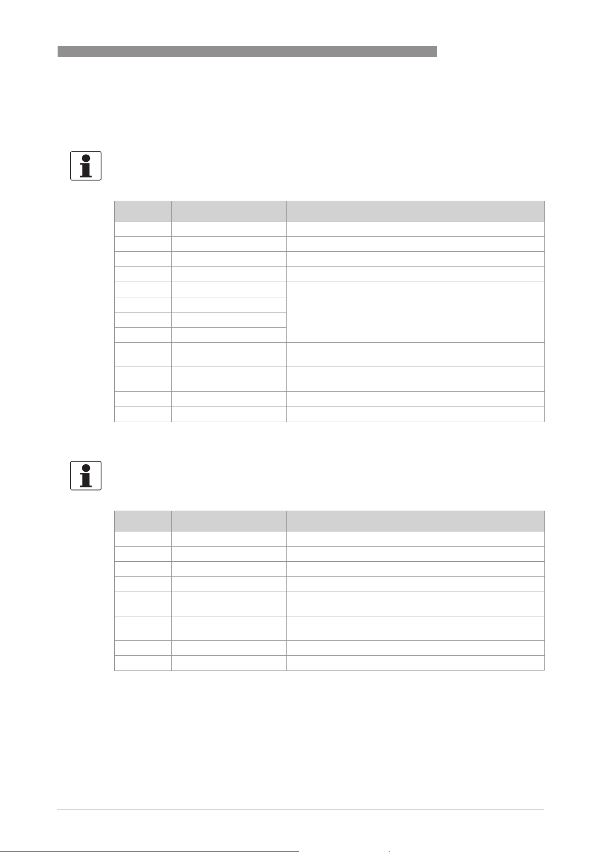
OPTISONIC 3400
6.4 Description of functions
6.4.1 Reset totaliser in the menu "Quick Setup"
INFORMATION!
It may be necessary to activate resetting of the totaliser in the menu "Quick Setup".
Key Display Description and setting
> Quick Setup Press and hold for 2.5 s, then release the key.
> Language 2 x ↓ Reset -
> Reset Errors -
↓ All Totaliser Select desired totaliser.
↓ Totaliser 1
↓ Totaliser 2
↓ Totaliser 3
> Reset Totaliser
No
↓ or ↑ Reset Totaliser
Yes
^ Totaliser 1,2 Totaliser has been reset.
3 x ^ Measuring mode -
-
-
OPERATION 6
6.4.2 Deleting error messages in the menu "Quick Setup"
INFORMATION!
The detailed list of the possible error messages.
Key Display Description and setting
> Quick Setup Press and hold for 2.5 s, then release the key.
> Language 2 x ↓ Reset -
> Reset Errors -
> Reset?
No
↓ or ↑ Reset?
Yes
^ Reset Errors Error has been reset.
3 x ^ Measuring mode -
-
-
www.krohne.com11/2013 - 4002037702 - HB OPTISONIC 3400 -en-R02
79
Page 80
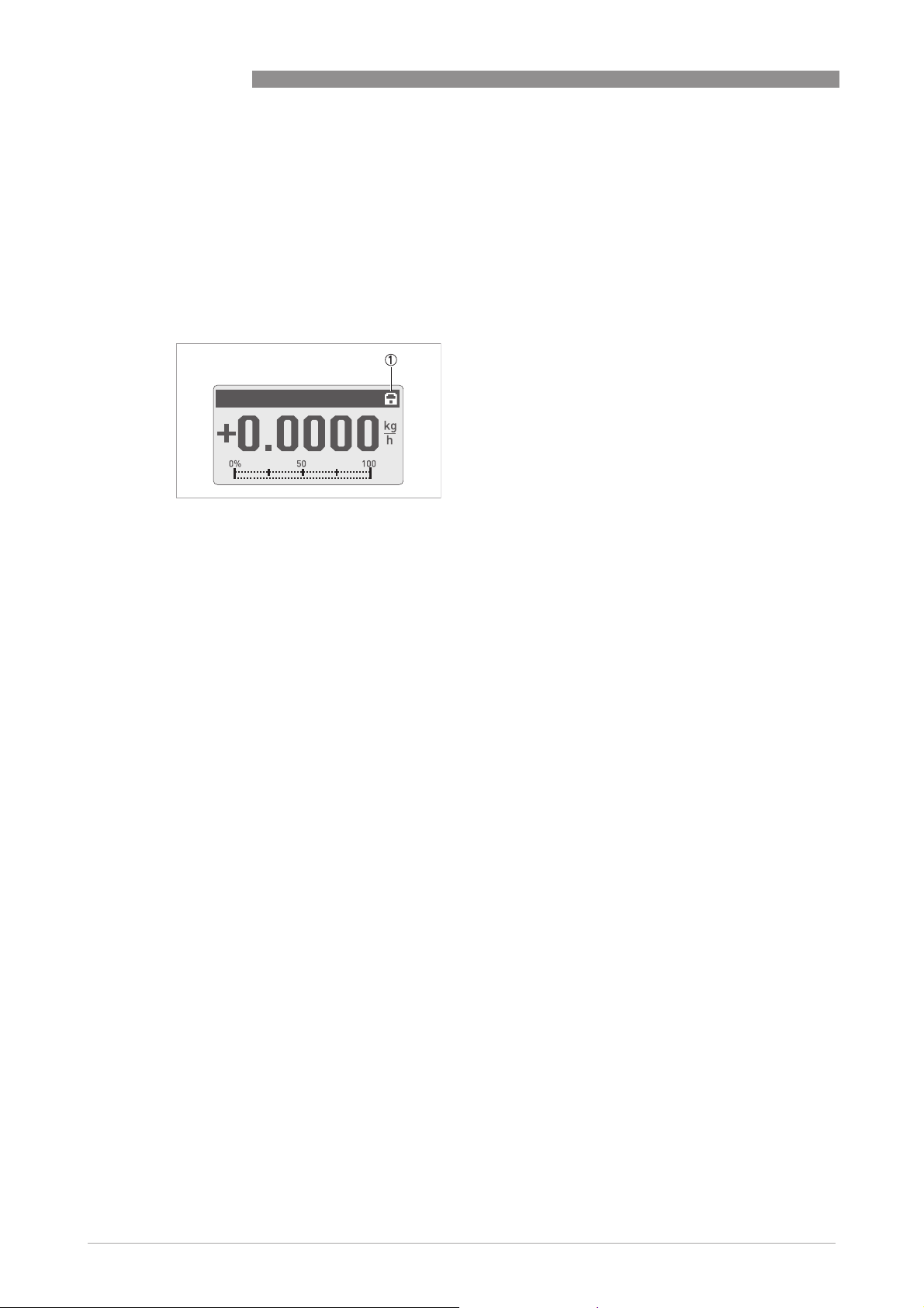
6 OPERATION
6.4.3 Diagnosis messages
These settings make it possible to change the status signal of the respective diagnosis message
(status group).
6.4.4 Optical keys
This function can deactivate the optical keys. In the display, the switched off state of the optical
keys is represented by a lock 1.
OPTISONIC 3400
In this case, the device may only be operated using the push buttons.
6.4.5 Graphic page
With this converter, the trend of the main measurement can be graphically displayed. The first
measurement on display page 1 is always defined as the main measurement.
• Menu C5.5.1 defines the range for the trend indicator (manual or automatic).
• Menu C5.5.2 defines the range for manual setting.
• Menu C5.5.3 defines the time span for the trend indicator.
6.4.6 Save settings
This function allows all settings to be stored in a memory.
• Backup 1: Saves settings in backup memory area 1
• Backup 2: Saves settings in backup memory area 2
6.4.7 Load settings
This function allows the complete stored settings to be loaded again.
• Backup 1: Loading from backup - memory 1
• Backup 2: Loading from backup - memory 2
• Factory: Uploading the original factory settings
80
www.krohne.com 11/2013 - 4002037702 - HB OPTISONIC 3400 -en-R02
Page 81

OPTISONIC 3400
6.4.8 Passwords
To create a password for the Quick Set menu or Setup menu, you must enter a 4-digit code into
the menu. You are then prompted for this password every time changes are to be made to the
corresponding menus. There is a hierarchy. The Setup password can also be used to perform
changes in the Quick Setup menu. Enter 0000 in each menu to disable the password.
6.4.9 Date and time
The signal converter has a real time clock which is used for all of the log functions in the device.
This function can be used to set the date and time of the real time clock.
6.4.10 Quick Access
In measuring mode, pressing the ^ key for 2.5 seconds carries out the "Quick Access" function.
Totalisers 1, 2, 3 and All Totalisers can be reset.
6.4.11 Low flow cutoff
The low flow cutoff can be individually set for each output and each display line. If the low flow
cutoff has been activated, the respective output or display is set to zero when the flow is below
the low flow cutoff value entered.
OPERATION 6
The value can either be entered as a percentage of the nominal flow of the sensor or, in the case
of a pulse output, as a discrete flow value.
Two values must be entered. The first is for the operating point of the sensor and the second is
for hysterisis. Condition: 1st value > 2nd value
1 Flow
2 Time
3 Currently indicated flow
4 Display set to zero
5 Currently indicated flow
6 Positive hysteresis
7 Operating point
8 Negative hysteresis
www.krohne.com11/2013 - 4002037702 - HB OPTISONIC 3400 -en-R02
81
Page 82

6 OPERATION
6.4.12 Time constant
To better process widely fluctuating measured values in the device, the measured values are
digitally filtered to stabilise the output. The time constant can be individually set for each output,
the first line of the display and the density measurement. However, keep in mind that the degree
of filtration affects the response time of the device in the event of rapid changes.
Short time constant Fast response times
Long time constant Slow response time
The time constant corresponds to the elapsed time until 67% of the end value has been reached
according to a step function.
6.4.13 Dual phase pulse output
A dual phase pulse or frequency output is possible. This operating mode requires 2 terminal
pairs. Terminal pairs A and B or D and B can be used.
OPTISONIC 3400
Fluctuating reading
Stable reading
In this case, perform the following settings:
• C2.3.11: Phase shift to D or shift to A
• All functions for output B are set using output D or output A.
• C2.5.11: Setting phase shift from output B relative to D, if terminal pair D was selected in
C2.3.11. 0°, 90° or 180° are offered as options.
6.4.14 Timeouts in programming mode
Normal menu function:
Normal menu function: If no key has been pressed for 5 minutes in a normal menu function, the
Normal menu function:Normal menu function:
display automatically switches to measuring mode. All changes are lost.
Test function:
Test function: In test mode, the test function is finished after 60 minutes.
Test function:Test function:
GDC IR Interface:
GDC IR Interface: If the GDC-IR connection is activated, it is cancelled after 60 seconds if no
GDC IR Interface:GDC IR Interface:
connection is established. If the connection is interrupted, the display can be operated again
after 60 seconds using the optical keys.
6.4.15 Output hardware
Depending on the hardware modules used (see CG number), it may be possible to change the
output options on terminals A, B, C or D in the menus C2.1.x. For example: A pulse output to a
frequency output or a status output to a control input.
82
The available options are determined by the hardware module used. It is not possible to change
the type of output, e.g. from active to passive or to NAMUR.
www.krohne.com 11/2013 - 4002037702 - HB OPTISONIC 3400 -en-R02
Page 83
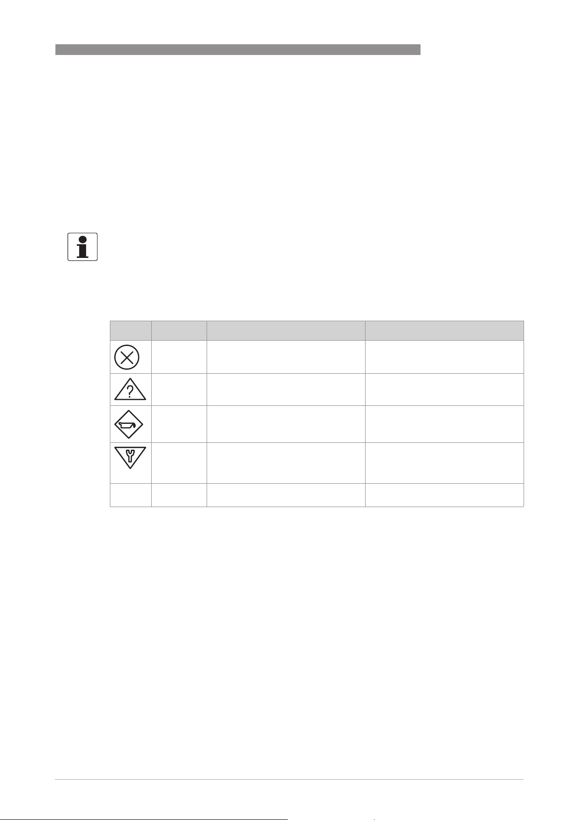
OPTISONIC 3400
6.5 Status messages and diagnostic information
The diagnostic messages are displayed in accordance with NAMUR standard NE 107. NE 107
states that there are up to 32 status groups which can have different status signals. NE 107 was
implemented with 16 status groups with fixed status signals and 8 groups with variable status
signals. To facilitate identification of the problem source, the status groups are then divided into
the groups: Sensor, Electronics, Configuration and Process.
OPERATION 6
The variable status signal can be changed in menu Mapping; C1.10.3 ...8
Mapping; C1.10.3 ...8. Changing the status
Mapping; C1.10.3 ...8Mapping; C1.10.3 ...8
signal to "Information", switches off the message.
INFORMATION!
As status message always the name of the relevant status group and the status signal (F/S/M/C)
is displayed.
Each status message (= status signal) has a specific symbol, determined by NAMUR, which is
displayed with the message. The length of each message is limited to one line.
Symbol Letter Status signal Description and consequence
FFFF Failure No measurement possible.
S Out of specification Measurements are available but are
M Maintenance required Measurements are still accurate but
C Function check A test function is active; The displayed
I Information No direct influence on the
no longer sufficiently accurate and
should be checked
this could soon change
or transferred measured value does
not correspond to the actual measured
value.
measurements
All status messages are saved in the status log (menu B3.1). Use the ↑ and ↓ keys to navigate
through this list. Use the ^ key to exit the list.
The status screen shows the status groups of all errors that have occurred since the last time
the status screen was opened. All errors that are not current disappear after 2 seconds. They
are shown in the list in brackets.
www.krohne.com11/2013 - 4002037702 - HB OPTISONIC 3400 -en-R02
83
Page 84

6 OPERATION
Legend
Fixed status signal
Variable status signal
OPTISONIC 3400
Error
Event group Single event Description Actions to eliminate the
type
FFFF F Sensor
FFFF F Electronics
FFFF F Configuration
Crossed cabling The measuring sensor
System Error Electronics error in internal
System Error A
System Error C
HW Combination Error
BM Failure
DM Failure
Frontend Failure
Mproc Failure
DSP Failure
Sensor driver Failure
Fieldbus Failure
PROFIBUS Failure
Modbus Failure
IO 1 Failure
IO 2 Failure
Tot 1 Failure
Tot 2 Failure
Tot 3 Failure
IO A Failure
IO B Failure
IO C Failure
BM Configuration Error detected when
DM Configuration
Process Input Config. Settings for process input
signals are out of range.
Flow measurements are not
possible.
bus communication or due
to a hardware error.
starting device. Possible
causes: inadmissible
parameter settings or fault
with electronics component.
invalid.
event
Check connection between
measuring sensor and
signal converter (remote
version).
Perform cold start. If
message reappears, contact
manufacturer.
Check settings of
appropriate function or load
factory settings. If the error
persists, contact
manufacturer.
Check settings for process
input or load factory
settings.
84
www.krohne.com 11/2013 - 4002037702 - HB OPTISONIC 3400 -en-R02
Page 85

OPTISONIC 3400
OPERATION 6
Error
Event group Single event Description Actions to eliminate the
type
FFFF F Process
C C Sensor
C C Electronics
event
Fieldbus Config. Check Fieldbus
PROFIBUS Config. Check PROFIBUS settings or
Tot 1 FB2 Unit Error Totaliser is out of operation
due to inadmissible unit.
Tot 2 FB3 Unit Error Check unit in totaliser 2 FB3
Tot 3 FB4 Unit Error Check unit in totaliser 3 FB4
Modbus Config. Check Modbus configuration
Display Config. Inadmissible settings for the
display
IO1 Configuration Inadmissible settings for IO1 Check settings for IO1 or
IO2 Configuration Inadmissible settings for IO2 Check settings for IO2 or
Tot 1 Configuration Inadmissible settings for
totaliser 1
Tot 2 Configuration Inadmissible settings for
totaliser 2
Tot 3 Configuration Inadmissible settings for
totaliser 3
IO A Configuration Inadmissible settings for IO ACheck settings for IO A or
IO B Configuration Inadmissible settings for IO BCheck settings for IO B or
IO C Configuration Inadmissible settings for IO CCheck settings for IO C or
IO D Configuration Inadmissible settings for IO DCheck settings for IO D or
configuration or load factory
settings.
load factory settings.
Check unit in totaliser 1 FB2
or load factory settings.
or load factory settings.
or load factory settings.
or load factory settings.
Check display settings or
load factory settings.
load factory settings.
load factory settings.
Check settings for totaliser 1
or load factory settings.
Check settings for totaliser 2
or load factory settings.
Check settings for totaliser 3
or load factory settings.
load factory settings.
load factory settings.
load factory settings.
load factory settings.
www.krohne.com11/2013 - 4002037702 - HB OPTISONIC 3400 -en-R02
85
Page 86

6 OPERATION
C C Configuration
C C Process
S S Sensor
S S Electronics
OPTISONIC 3400
Flow Simulation Active Simulation of volume flow,
VoS Simulation Active Simulation of a certain
Fieldbus Sim. Active The simulation function in
PROFIBUS Sim. Active The simulation function in
IO A Simulation Active IO A simulation is active. Switch off simulation.
IO B Simulation Active IO B simulation is active.
IO C Simulation Active IO C simulation is active.
IO D Simulation Active IO D simulation is active.
Electr.Temp.A Out of Spec Temperature of the signal
Electr.Temp.C Out of Spec
Converter zero too large Converter zero too large Recalibrate the converter or
mass flow.
velocity of sound (VoS)
the Foundation Fieldbus
module is active and being
used.
the PROFIBUS module is
active and being used.
converter electronics is out
of range.
Switch off measured value
simulation.
Switch off measured value
simulation.
Check Fieldbus settings.
Check PROFIBUS settings.
Protect signal converter
from process effects and
sunlight.
contact manufacturer
86
www.krohne.com 11/2013 - 4002037702 - HB OPTISONIC 3400 -en-R02
Page 87

OPTISONIC 3400
S S Configuration
S S Process
M M Sensor
M M Electronics
M M
Configuration
M M Process
FFFF F Proc: Current
Input
OPERATION 6
PROFIBUS Uncertain
IO A Overrange The output value is limited
IO B Overrange
IO C Overrange
IO D Overrange
Mass Flow Out of Range The flow is out of range. The
Vol. Flow Out of Range
Velocity Out of Range
Backplane Data Faulty The backplane data record is
Factory Data Faulty Factory settings are invalid. Contact manufacturer.
Backplane Difference The data on the backplane
PROFIBUS Baudrate The PROFIBUS searches for
Backup 1 Data Faulty Error when checking the
Backup 2 Data Faulty Error when checking the
by a filter.
actual flow is higher than
the displayed value.
faulty.
differ from the data in the
device.
the current Baudrate.
data record for Backup 1.
data record for Backup 2.
Check the range setting of
the output.
Check process conditions.
Check the correct
installation of the signal
converter electronics. After
changing one parameter,
the message should
disappear within one
minute. If not, contact the
manufacturer.
After changing one
parameter, the message
should disappear within one
minute. If not, contact the
manufacturer.
Use "Setup > Device >
Special Functions > Save
Settings" to save the data
record. If the message
continues to appear, contact
the manufacturer.
www.krohne.com11/2013 - 4002037702 - HB OPTISONIC 3400 -en-R02
87
Page 88

6 OPERATION
OPTISONIC 3400
S S Electr: IO
Connection
SSSS S Proc: Empty
pipe
S S Proc: Signal
lost
S S Proc: Signal
unreliable
S S Config:
Totaliser
I S Proc: System
Control
IO A Connection Current output A cannot
IO A Connection Open circuit or short circuit
IO B Connection Current output B cannot
IO B Connection Open circuit or short circuit
IO C Open Connector Current output C cannot
Empty pipe All relevant paths have lost
Signal lost path 1 No signal present in path 1
Signal lost path 2
Signal lost path 3
Path 1 unreliable The sensor signals do not
Path 2 unreliable
Path 3 unreliable
Time of flight unreliable
Tot 1 FB2 Overflow Totaliser has overflowed and
Tot 2 FB3 Overflow
Tot 3 FB4 Overflow
Tot 1 Overflow
Tot 2 Overflow
Tot 3 Overflow
provide the necessary
current. The current
provided is too low. The
current at Input A is below
0.5 mA or above 23 mA.
at IO A.
provide the necessary
current. The current
provided is too low. The
current at Input B is below
0.5 mA or above 23 mA.
at IO B.
provide the necessary
current.
The current provided is too
low.
their signal. The most
obvious reason is the
absence of liquid in the
sensor.
(2,3) of the sensor.
reach the expected
amplitude. This can
influence the measuring
accuracy.
started again at zero
Check connection at A.
Measure resistance of
current loop at A.
Check current at A.
Check connection at B.
Measure resistance of
current loop at B.
Check current at B.
Check connection at C.
Measure resistance of
current loop at C.
Fill the sensor with liquid to
return to normal operation.
Remove the dampening or
blockage in path 1 (2,3) in
the sensor
Check the acoustic
properties of the medium.
Particles, air bubbles or
inhomogeneity, may cause
an instable signal. Check
gain and SNR in this path
Check totaliser format.
88
www.krohne.com 11/2013 - 4002037702 - HB OPTISONIC 3400 -en-R02
Page 89

OPTISONIC 3400
OPERATION 6
I S Electr: Power
Failure
I I Electr.
Operation Info.
Tot 1 Power Failure Power failure has occurred.
Tot 2 Power Failure
Tot 3 Power Failure
Power Failure Detected
Zero Calibr. Running A zero calibration in
Sensor Starting up. Sensor starts up. This is
PROFIBUS: no data No data exchange via
Tot 1 Stopped Totaliser 1 was stopped. If totaliser is to continue
Tot 2 Stopped Totaliser 2 was stopped.
Tot 3 Stopped Totaliser 3 was stopped.
Control In A Active
Control In B Active
Status Out A Active
Status Out B Active
Status Out C Active
Status Out D Active
Disp. 1 Overrange The value in the 1st
Disp. 2 Overrange The value in the 2nd
Optical Interf. Active The optical interface is being
The totaliser state may be
invalid.
progress.
normal operation at the
beginning of measuring
mode. Other error
messages are suppressed
PROFIBUS.
measurement line of the
display page is limited.
measurement line of the
display page is limited.
used. The optical keys are
deactivated.
Check the value of the
totaliser.
Wait until finished
After some moments, the
converter will act and
respond with the converter
status.
counting, select "Yes" in
Fct. C.y.9 (Start Totaliser).
Check setting for 1st
measurement line.
Check setting for 2nd
measurement line.
The keys are ready for
operation again approx. 60
seconds after the end of the
data transfer/removal of the
optical interface.
www.krohne.com11/2013 - 4002037702 - HB OPTISONIC 3400 -en-R02
89
Page 90

7 SERVICE
7.1 Spare parts availability
The manufacturer adheres to the basic principle that functionally adequate spare parts for each
device or each important accessory part will be kept available for a period of 3 years after
delivery of the last production run for the device.
This regulation only applies to spare parts which are subject to wear and tear under normal
operating conditions.
7.2 Availability of services
The manufacturer offers a range of services to support the customer after expiration of the
warranty. These include repair, maintenance, technical support and training.
INFORMATION!
For more precise information, please contact your local sales office.
7.3 Returning the device to the manufacturer
OPTISONIC 3400
7.3.1 General information
This device has been carefully manufactured and tested. If installed and operated in accordance
with these operating instructions, it will rarely present any problems.
CAUTION!
Should you nevertheless need to return a device for inspection or repair, please pay strict
attention to the following points:
•
Due to statutory regulations on environmental protection and safeguarding the health and
safety of our personnel, manufacturer may only handle, test and repair returned devices that
have been in contact with products without risk to personnel and environment.
•
This means that the manufacturer can only service this device if it is accompanied by the
following certificate (see next section) confirming that the device is safe to handle.
CAUTION!
If the device has been operated with toxic, caustic, flammable or water-endangering products,
you are kindly requested:
•
to check and ensure, if necessary by rinsing or neutralising, that all cavities are free from
such dangerous substances,
•
to enclose a certificate with the device confirming that is safe to handle and stating the
product used.
90
www.krohne.com 11/2013 - 4002037702 - HB OPTISONIC 3400 -en-R02
Page 91

OPTISONIC 3400
7.3.2 Form (for copying) to accompany a returned device
Company: Address:
Department: Name:
Tel. no.: Fax no.:
Manufacturer's order no. or serial no.:
The device has been operated with the following medium:
SERVICE 7
This medium is: water-hazardous
toxic
caustic
flammable
We checked that all cavities in the device are free from such
substances.
We have flushed out and neutralized all cavities in the
device.
We hereby confirm that there is no risk to persons or the environment through any residual media
contained in the device when it is returned.
Date: Signature:
Stamp:
7.4 Disposal
CAUTION!
Disposal must be carried out in accordance with legislation applicable in your country.
www.krohne.com11/2013 - 4002037702 - HB OPTISONIC 3400 -en-R02
91
Page 92
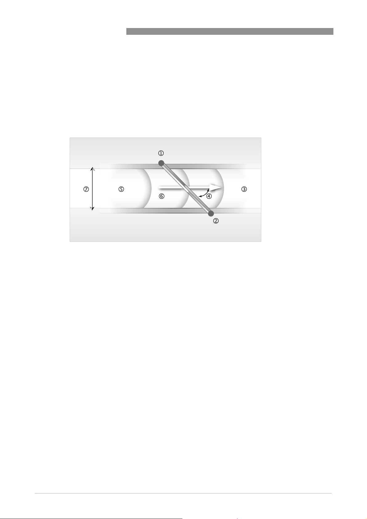
8 TECHNICAL DATA
8.1 Measuring principle
• Like canoes crossing a river, acoustic signals are transmitted and received along a diagonal
measuring path.
• A sound wave going downstream with the flow travels faster than a sound wave going
upstream against the flow.
• The difference in transit time is directly proportional to the mean flow velocity of the medium.
OPTISONIC 3400
Figure 8-1: Measuring principle
1 Transducer A
2 Transducer B
3 Flow velocity
4 Angle of incidence
5 Velocity of sound of liquid
6 Path length
7 Inner diameter
92
www.krohne.com 11/2013 - 4002037702 - HB OPTISONIC 3400 -en-R02
Page 93

OPTISONIC 3400
8.2 Technical data
INFORMATION!
•
The following data is provided for general applications. If you require data that is more
relevant to your specific application, please contact us or your local sales office.
•
Additional information (certificates, special tools, software,...) and complete product
documentation can be downloaded free of charge from the website (Download Center).
Measuring system
Measuring principle Ultrasonic transit time
Application range Flow measurement of (non) conductive fluids
Measured value
Measured value
Measured valueMeasured value
Primary measured value Transit time
Secondary measured values Volume flow, mass flow, flow speed, flow direction,
TECHNICAL DATA 8
velocity of sound, gain, signal to noise ratio, reliability of
flow measurement, totalised volume or mass
Design
Features 3 parallel acoustic path fully welded.
Modular construction The measurement system consists of a measuring sensor
Compact version OPTISONIC 3400
Remote version OPTISONIC 3000 F with UFC 400 signal converter
Nominal diameter DN25...3000 / 1...120"
Measurement range 0.3...20 m/s / 0.98...65 ft/s
Signal converter
Signal converter
Signal converterSignal converter
Inputs / outputs
Totaliser 2 (optional 3) internal totalisers with a max. of 8 digits
Verification and self-diagnostics Integrated verification, diagnostic functions: measuring
Communication interfaces
and a signal converter.
Current (incl. HART®), pulse, frequency and/or status
output, limit switch and/or control input (depending on
the I/O version)
(e.g. for totalising volume and/or mass units)
device, process, measured values, device configuration,
etc.
Modbus RS485, HART® 7, Foundation Fieldbus ITK6,
Profibus PA Profile 3.02
www.krohne.com11/2013 - 4002037702 - HB OPTISONIC 3400 -en-R02
93
Page 94

8 TECHNICAL DATA
Display and user interface
Display and user interface
Display and user interfaceDisplay and user interface
Graphic display LC display, backlit white
Operating elements 4 optical and push buttons for operator control of the
Remote operation
Display functions
Display functions
Display functionsDisplay functions
Operating menu Programming of parameters at 2 measured value pages,
Language of display texts English, French, German
Measurement functions Units:
Diagnostic functions Standards:
OPTISONIC 3400
Size: 128x64 pixels, corresponds to 59x31 mm =
2.32"x1.22"
Display turnable in 90° steps.
signal converter without opening the housing.
Option: Infrared interface (GDC)
PACTwareTM including Device Type Manager (DTM)
HART® handheld communicator (Emerson), AMS
(Emerson), PDM (Siemens)
All DTM's and drivers will be available at the internet
homepage of the manufacturer.
1 status page, 1 graphic page (measured values and
descriptions adjustable as required)
Units: Metric, British and US units selectable as desired
Units:Units:
from lists for volume/mass flow and counting, velocity,
temperature.
Measured values:
Measured values: volume flow, mass flow, flow speed,
Measured values:Measured values:
velocity of sound, gain, signal to noise ratio, flow
direction, diagnostics
Standards: VDI/NAMUR NE 107
Standards:Standards:
Status messages:
Status messages: Output of status messages via display,
Status messages:Status messages:
current and/or status output, HART
interface
Sensor diagnostics:
Sensor diagnostics: per acoustic path velocity of sound,
Sensor diagnostics:Sensor diagnostics:
flow speed, gain, signal to noise ratio
Process diagnostics:
Process diagnostics: empty pipe, signal integrity, cabling,
Process diagnostics:Process diagnostics:
flow conditions
Signal converter diagnostics:
Signal converter diagnostics: data bus monitoring, I/O
Signal converter diagnostics:Signal converter diagnostics:
connections, electronics temperature, parameter and
data integrity
®
or via other bus
94
Measuring accuracy
Reference conditions
Reference conditions
Reference conditions Reference conditions
Medium Water
Temperature 20°C / 68°F
Pressure 1 bar / 14.5 psi
Inlet section 10 DN
Maximum measuring error
Maximum measuring error
Maximum measuring errorMaximum measuring error
Standard: ±0.3% ±2 mm/s of actual measured flow rate
Repeatability ±0.2%
www.krohne.com 11/2013 - 4002037702 - HB OPTISONIC 3400 -en-R02
Page 95

OPTISONIC 3400
Operating conditions
Temperature
Temperature
TemperatureTemperature
Process temperature Compact version:
Ambient temperature Depending on the version and combination of outputs
Protect inside electronics against self-heating (increasing of the electronics temperature will lead to a
reduction of the corresponding service life by a factor 2 for each step of 10°C / 50°F increase).
Protect the signal converter from external heat sources such as direct sunlight, as higher temperatures
reduce the life cycle of all electronic components.
Storage temperature -50…+70°C / -58…+158°F
Pressure
Pressure
PressurePressure
Atmospheric
EN 1092-1 DN25…50: PN 40
ASME B16.5 1…24": 150 lb RF
JIS DN25...40: 20K
Properties of medium
Properties of medium
Properties of mediumProperties of medium
Physical condition Liquid, single phase (well mixed, rather clean)
Permissible gas content ≤ 2% (volume)
Permissible solid content ≤ 5% (volume)
Viscosity Standard:
TECHNICAL DATA 8
Compact version: -45...+140°C / -49...+284°F
Compact version:Compact version:
(for stainless steel housing at ambient temperature ≤
45°C / +113°F)
Remote version:
Remote version: -45...+180°C / -49...+356°F
Remote version:Remote version:
Extended temperature version:
Extended temperature version: -45...+250°C / -49...+482°F
Extended temperature version:Extended temperature version:
(only remote version)
Cryogenic version:
Cryogenic version: -200...+180°C / -328...+356°F (only
Cryogenic version:Cryogenic version:
remote version, IP68, complete stainless steel)
Carbon steel flanges;
minimal process temperatures acc. to EN1092: -10°C /
+14°F; ASME: -29°C / -20°F
-40…+65°C / -40…+149°F
Option (stainless steel converter housing): -40...+60°C / -
40...+140°F
Ambient temperatures below -25°C / -13°F may affect the
readability of the display.
DN100…150: PN 16
DN200…1000: PN 10
DN1200…2000: PN 6
DN2200...3000: PN 2.5
Higher pressure ratings on request
1…24": 300 lb RF
1…24": 600 lb RF
1...24": 900 lb RF
Larger diameters on request.
DN50...300: 10K
Standard: Up to 100 cSt (for all diameters)
Standard:Standard:
Option:
Option: High viscosity variant up to 1000 cSt
Option:Option:
www.krohne.com11/2013 - 4002037702 - HB OPTISONIC 3400 -en-R02
95
Page 96

8 TECHNICAL DATA
Installation conditions
Installation conditions
Installation conditionsInstallation conditions
Installation For detailed information refer to
Inlet run Minimal 5 DN (straight inlet)
Outlet run Minimal 3 DN (straight outlet)
Dimensions and weights For detailed information refer to
Materials
Materials
MaterialsMaterials
Measuring sensor
Measuring sensor
Measuring sensorMeasuring sensor
Flanges
(wetted)
Measuring Tube
(wetted)
Measuring sensor housing DN25...65 / 1"...2.5": Stainless steel 1.4404 (AISI 316L)
Transducer
Transducers (wetted) Stainless steel 1.4404 (AISI 316L)
Transducer holders
incl. caps
Tube transducer cabling Stainless steel 1.4404 (AISI 316L)
Connection box and connection box support
(remote version only)
Coating (measuring sensor) Standard: Polyurethane
NACE conformity On request; wetted materials conform NACE MR 175/103
Signal converter
Signal converter
Signal converterSignal converter
Housing Versions C and F: Die-cast aluminium
Coating Standard: Polyurethane
OPTISONIC 3400
Installation
If no details are known, minimal 10 DN recommended
If no details are known, minimal 5 DN recommended
on page 18.
Dimensions and weights
on page 105.
DN25...65 / 1"...2.5 ": Stainless steel 1.4404 (AISI 316L)
DN80...3000 / 3"...120": Carbon steel
Other materials on request.
DN25...300 / 1"...12": Stainless steel 1.4404 (AISI 316L),
some 316Ti / 1.4571
DN350..3000 / 14"...120": Carbon steel
Other materials on request.
DN80...3000 / 3"...120": Carbon steel
Other materials on request.
DN350...3000 / 14"...120"; Stainless steel 1.4404 (AISI
316L) (same material as flanges)
Standard: Die-cast aluminium; polyurethane coated
Option: Stainless steel 316 (1.4408)
Option: Offshore coating
Option: Stainless steel 316 (1.4408)
Option: Offshore coating
96
www.krohne.com 11/2013 - 4002037702 - HB OPTISONIC 3400 -en-R02
Page 97

OPTISONIC 3400
Electrical connections
Electrical connections
Electrical connectionsElectrical connections
Description of used abbreviations; Q=xxx; I
= external voltage; U
General Electrical connection is carried out in conformity with the
Power supply Standard: 100…230 VAC (-15% / +10%), 50/60 Hz
Power consumption AC: 22 VA
Signal cable
(remote version only)
Cable entries Standard: M20 x 1.5 (8...12 mm)
= maximal internal voltage
int, max
TECHNICAL DATA 8
= maximum current; Uin = xxx; U
max
VDE 0100 directive "Regulations for electrical power
installations with line voltages up to 1000 V" or equivalent
national specifications.
Option: 24 VAC/DC (AC: -15% / +10%; DC: -25% / +30%)
DC: 12 W
MR06 (shielded cable with 6 coax cores): Ø 10.6 mm / 0.4"
5 m / 16 ft
Option: 10...30 m / 33...98 ft
Option: ½" NPT, PF ½
= internal voltage; U
int
ext
Inputs and outputs
General All outputs are electrically isolated from each other and
Description of used abbreviations U
from all other circuits.
All operating data and output values can be adjusted.
= external voltage; RL = load + resistance;
ext
= terminal voltage; I
U
0
= nominal current
nom
Safety limit values (Ex i):
= max. input voltage; Ii = max. input current; Pi = max.
U
i
input power rating;
Ci = max. input capacity; Li = max. input inductivity
www.krohne.com11/2013 - 4002037702 - HB OPTISONIC 3400 -en-R02
97
Page 98

8 TECHNICAL DATA
Current output
Current output
Current outputCurrent output
Output data Measurement of volume flow, mass flow, flow speed,
Temperature coefficient Typically ±30 ppm/K
Settings
Operating data Basic I/Os
Active U
OPTISONIC 3400
velocity of sound, gain, SNR, diagnostics 1, 2, NAMUR
NE107, HART
Without HART
Without HART
Without HARTWithout HART
Q = 0%: 0…20 mA; Q = 100%: 10…20 mA
Error identification: 3…22 mA
With HART
With HART
With HARTWith HART
Q = 0%: 4…20 mA; Q = 100%: 10…20 mA
Error identification: 3…22 mA
Q = 100%: 10…20 mA
Error identification: 3…22 mA
Basic I/Os Modular I/Os
Basic I/OsBasic I/Os
int, nom
®
communication.
®
®
= 24 VDC
Modular I/Os Ex i
Modular I/OsModular I/Os
Ex i
Ex iEx i
U
int, nom
= 20 VDC
Passive U
I ≤ 22 mA
≤ 1kΩ
R
L
≤ 32 VDC
ext
I ≤ 22 mA
≥ 1.8 V
U
0
R
= (U
L, max
- U0 / I
ext
max
I ≤ 22 mA
≤ 450 Ω
R
L
U0=21V
I0=90mA
=0.5W
P
0
C0= 90 nF / L0 =
2mH
=110nF/
C
0
L0=0.5mH
U
≤ 32 VDC
ext
I ≤ 22 mA
≥ 4V
U
0
R
= (U
L, max
U
0
/ I
max
ext
-
Ui=30V
Ii= 100 mA
=1W
P
i
C
= 10 nF
i
~0mH
L
i
98
www.krohne.com 11/2013 - 4002037702 - HB OPTISONIC 3400 -en-R02
Page 99

OPTISONIC 3400
HART
HART
HARTHART
Description
Load
Multidrop Yes, current output = 4 mA
Device drivers DD for FC 375/475, AMS, PDM, DTM for FDT
Pulse or frequency output
Pulse or frequency output
Pulse or frequency outputPulse or frequency output
Output data Volume flow, mass flow
Function Adjustable as pulse of frequency output
Pulse rate/frequency 0.01...10000 pulses/s or Hz
Settings For Q = 100%: 0.01... 10000 pulses per second or pulses
Operating data Basic I/Os Modular I/Os Ex i
Active - U
TECHNICAL DATA 8
®
HART® protocol via active and passive current output
HART® version: V7
Universal HART® parameter: completely integrated
≥ 250 Ω t HART® test point:
Note maximum load for current output!
Multidrop addresses adjustable in operation menu 1...15
per unit volume.
Pulse width: adjustable as automatic, symmetric or fixed
(0.05...2000 ms)
= 24 VDC -
nom
f
in operating
max
menu set to:
ffff
≤ 100 Hz:
100 Hz:
100 Hz: 100 Hz:
max
max
maxmax
I ≤ 20 mA
= 47 kΩ
R
L, max
open:
I ≤ 0.05 mA
closed:
=24V at
U
0,nom
I=20mA
F
in operating
max
menu set to:
≤ 10
100 Hz < f
100 Hz < f
100 Hz < f100 Hz < f
kHz:
kHz:
kHz:kHz:
max
max
maxmax
10
10 10
I ≤ 20 mA
RL ≤ 10 kΩ for f ≤
1 kHz
≤ 1 kΩ for f ≤
R
L
10 kHz
open:
I ≤ 0.05 mA
closed:
U
= 22.5 V at
0,nom
I=1mA
= 21.5 V at
U
0,nom
I=10mA
U
0,nom
=19V at
I=20mA
www.krohne.com11/2013 - 4002037702 - HB OPTISONIC 3400 -en-R02
99
Page 100

8 TECHNICAL DATA
OPTISONIC 3400
Passive U
≤ 32 VDC -
ext
f
in operating menu set to:
max
≤ 100 Hz:
100 Hz:
ffff
100 Hz: 100 Hz:
max
max
maxmax
I ≤ 100 mA
R
= 47 kΩ
L, max
= (U
R
L, max
- U0) / I
ext
max
open:
I ≤ 0.05 mA at U
=32VDC
ext
closed:
=0.2V at I≤ 10 mA
U
0, max
U
= 2 V at I ≤ 100 mA
0, max
f
in operating menu set to:
max
100 Hz < f
100 Hz < f
100 Hz < f100 Hz < f
≤ 10 kHz:
max
max
maxmax
10 kHz:
10 kHz: 10 kHz:
I ≤ 20 mA
RL ≤ 10 kΩ for f ≤ 1 kHz
≤ 1 kΩ for f ≤ 10 kHz
R
L
R
= (U
L, max
- U0) / I
ext
max
open:
I ≤ 0.05 mA at U
= 32 VDC
ext
closed:
U
=1.5V at I≤ 1mA
0, max
=2.5V at I≤ 10 mA
U
0, max
U
=5.0V at I≤ 20 mA
0, max
NAMUR - Passive to
EN 60947-5-6
Passive to
EN 60947-5-6
open:
I
= 0.6 mA
nom
closed:
=3.8mA
I
nom
open:
I
=0.43mA
nom
closed:
= 4.5 mA
I
nom
Ui=30V
= 100 mA
I
i
=1W
P
i
Ci=10nF
=0mH
L
i
100
www.krohne.com 11/2013 - 4002037702 - HB OPTISONIC 3400 -en-R02
 Loading...