

Page 1
Technical Datasheet
Technical Datasheet
OPTIMASS 7400
OPTIMASS 7400
OPTIMASS 7400OPTIMASS 7400
Technical DatasheetTechnical Datasheet
Sensor for mass flow
•
The optimum meter for demanding applications
•
A single straight measuring tube
•
Choice of 4 tube materials
The documentation is only complete when used in combination with the relevant
documentation for the signal converter.
© KROHNE 09/2017 - 4004537602 - TD OPTIMASS 7400 R02 en
Page 2

CONTENTS
OPTIMASS 7400
1 Product features 3
1.1 Overview............................................................................................................................ 3
1.2 Features and options........................................................................................................ 5
1.3 Meter / converter combinations....................................................................................... 5
1.4 Measuring principle (single tube) .................................................................................... 6
2 Technical data 8
2.1 Technical data................................................................................................................... 8
2.1.1 ATEX (acc. 94/9/EC)............................................................................................................... 12
2.1.2 ATEX (acc. 94/9/EC) temperature limits............................................................................... 12
2.2 Maximum end loadings .................................................................................................. 13
2.3 Measuring accuracy ....................................................................................................... 14
2.4 Guidelines for maximum operating pressure................................................................ 15
2.5 Dimensions and weights ................................................................................................ 20
2.5.1 Flanged versions................................................................................................................... 20
2.5.2 Hygienic versions .................................................................................................................. 23
2.5.3 Heating jacket version .......................................................................................................... 29
2.5.4 Purge port option .................................................................................................................. 30
3 Installation 31
3.1 Intended use ................................................................................................................... 31
3.2 Mounting restrictions ..................................................................................................... 31
3.2.1 General installation principles ............................................................................................. 31
3.2.2 Sunshades............................................................................................................................. 33
4 Notes 34
2
www.krohne.com 09/2017 - 4004537602 - TD OPTIMASS 7400 R02 en
Page 3

OPTIMASS 7400
1.1 Overview
The OPTIMASS 7400 is the only sensor for mass flow with a single straight measuring tube that
is available in Titanium, Stainless Steel, Hastelloy
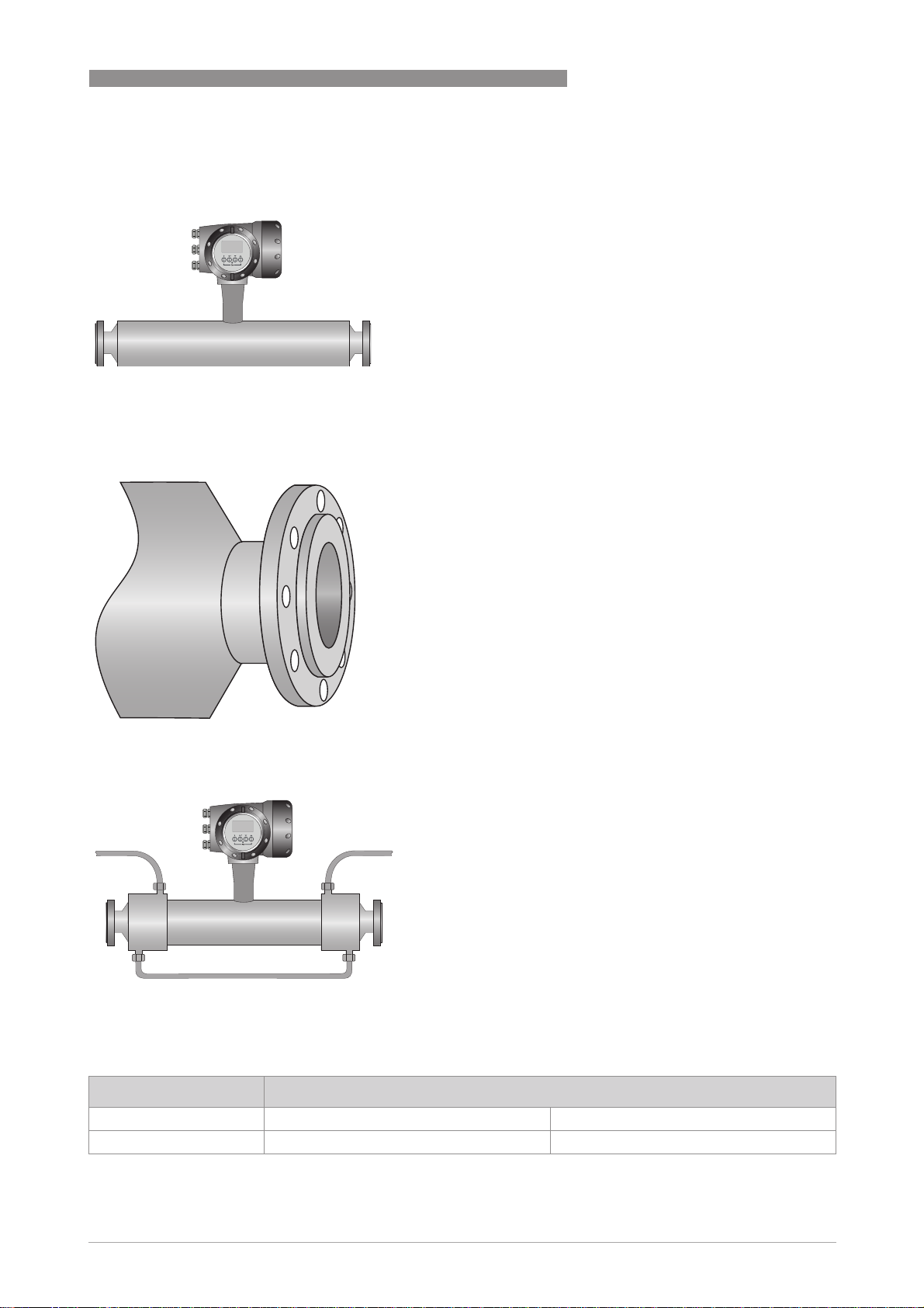
Compact version
PRODUCT FEATURES
®
or Tantalum.
1
1 Modular electronics with a range of output options (see separate documentation for details).
2 The power of the MFC 400 gives comprehensive diagnositcs together with Entrained Gas Management (EGM).
3 Available with a range of flange and hygienic connections.
Remote version
1 Remote terminal box.
www.krohne.com09/2017 - 4004537602 - TD OPTIMASS 7400 R02 en
3
Page 4

1
PRODUCT FEATURES
Highlights
• Outer cylinder typical burst pressure greater than 100 barg / 1450 psig, with optional PED
approved secondary pressure containment available
• Easily drained and easy to clean
• Resistant to installation and process effects
• Excellent zero stability
• Low energy consumption, means lower operating costs
• Rapid signal processing, even with product / temperature changes
• Modular electronics with data redundancy - "plug & play" replacement of electronics
Industries
• Water & wastewater
• Mining & building materials
• Iron, steel and metal processing
• Food & beverage
• Oil, gas and alternative fuels
• Paper & pulp
• Petrochemical industry
• Pharmaceutical industry
• Chemical industry
OPTIMASS 7400
Applications
• Viscous or shear-sensitive products
• Products requiring low flow velocities
• Non-homogeneous mixtures
• Products with entrained solids or gas
• Custody transfer
• Loading and product transfer measurement
• Slurries
• Highly corrosive fluids
4
www.krohne.com 09/2017 - 4004537602 - TD OPTIMASS 7400 R02 en
Page 5
OPTIMASS 7400
1.2 Features and options
Features
Connection options
PRODUCT FEATURES
• Available as compact or remote.
• Low pressure loss - single straight tube design
guarantees a low pressure drop across the
meter.
• Self Draining.
• Easy to clean.
• With advanced Entrained Gas Management
• A range of flanges up to ASME 600 / PN100.
• Supports a wide range of industry standard
• Adaptable to suit customer's hygienic
TM
(EGM
wide range of gas fractions and complex flow
conditions.
hygienic connections.
connections.
) the meter maintains operation over a
1
Heating jacket and purge port
• Heating jacket option for use with temperature
dependant products.
• Prevents solidification of process product.
• Purge port option for protection in the event of
measuring tube failure.
• Allows hazardous chemicals to be drained away
safely.
• Can also be used for the early detection of
measuring tube failure where highly toxic
chemicals are being measured.
1.3 Meter / converter combinations
Converter MFC 400
Configuration Compact Remote field
OPTIMASS 7400 7400C 7400F
www.krohne.com09/2017 - 4004537602 - TD OPTIMASS 7400 R02 en
5
Page 6
1
PRODUCT FEATURES
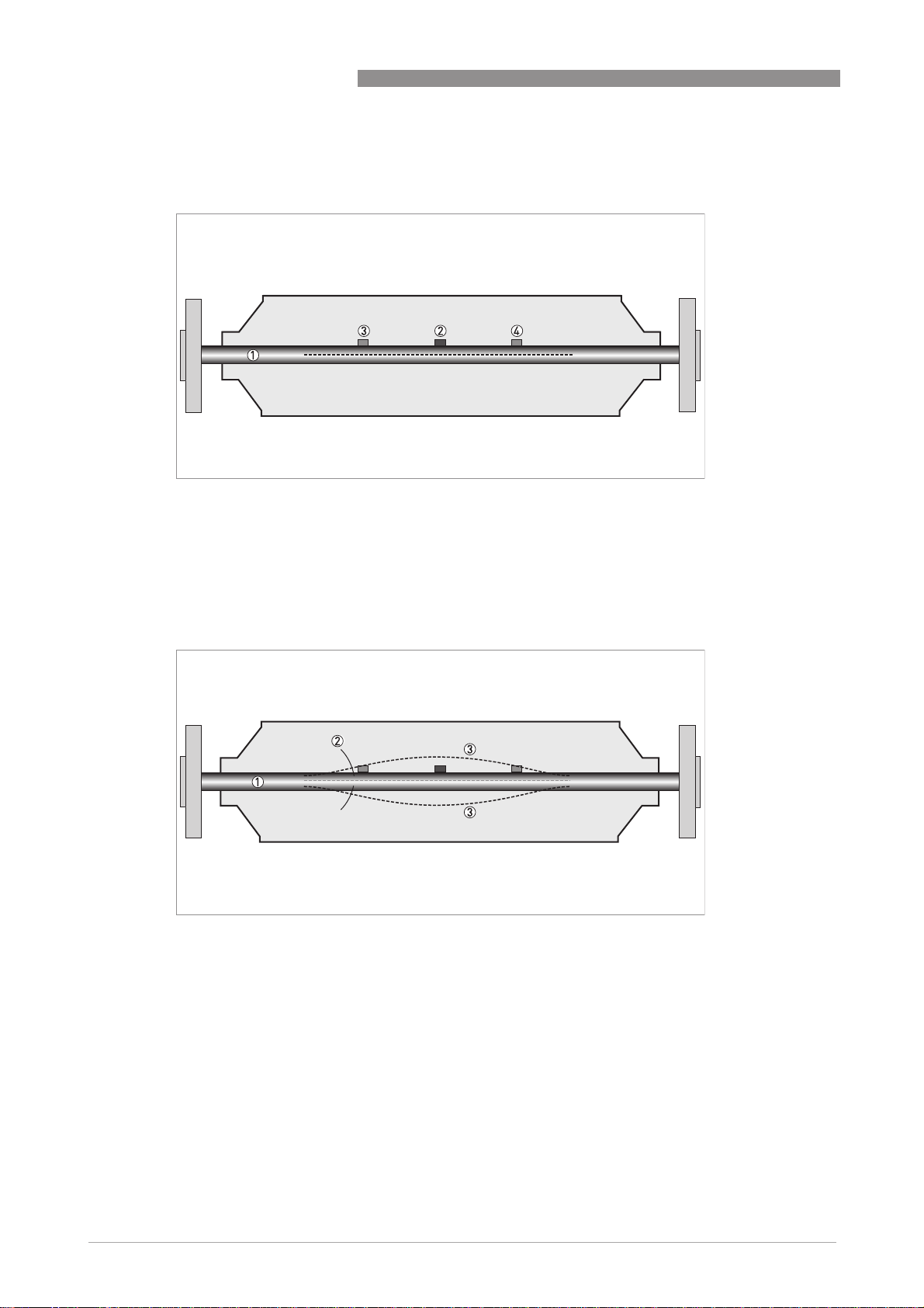
1.4 Measuring principle (single tube)
Static meter not energised and with no flow
1 Measuring tube
2 Drive coil
3 Sensor 1
4 Sensor 2
OPTIMASS 7400
A Coriolis single tube mass flowmeter consists of a single measuring tube 1 a drive coil 2 and
two sensors (3 and 4) that are positioned either side of the drive coil.
Energised meter
1 Measuring tubes
2 Direction of oscilation
3 Sine wave
When the meter is energised, the drive coil vibrates the measuring tube causing it to oscillate
and produce a sine wave 3. The sine wave is monitored by the two sensors.
6
www.krohne.com 09/2017 - 4004537602 - TD OPTIMASS 7400 R02 en
Page 7
OPTIMASS 7400
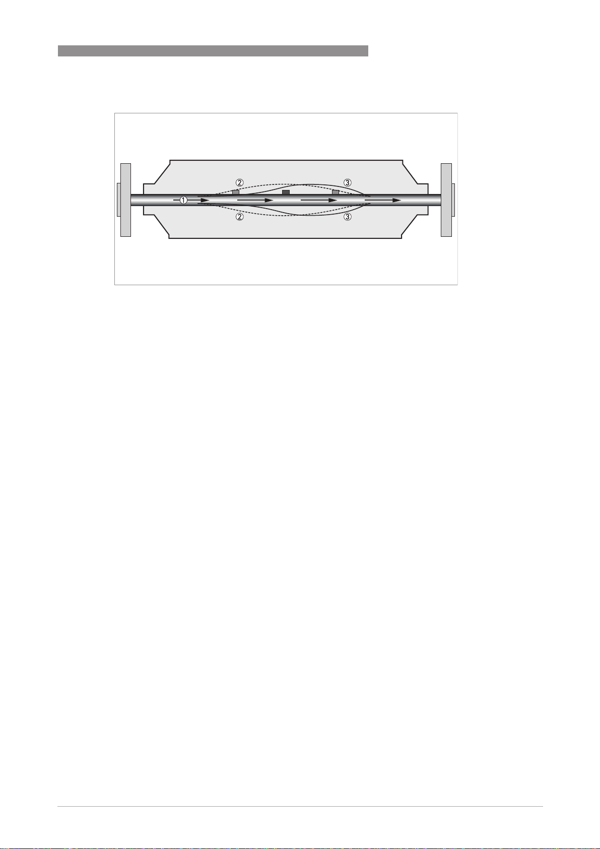
Energised meter with process flow
1 Process flow
2 Sine wave
3 Phase shift
When a fluid or gas passes through the tube, the coriolis effect causes a phase shift in the sine
wave that is detected by the two sensors. This phase shift is directly proportional to the mass
flow.
Density measurement is made by evaluation of the frequency of vibration and temperature
measurement is made using a Pt500 sensor.
PRODUCT FEATURES
1
www.krohne.com09/2017 - 4004537602 - TD OPTIMASS 7400 R02 en
7
Page 8

2
TECHNICAL DATA
OPTIMASS 7400
2.1 Technical data
•
The following data is provided for general applications. If you require data that is more
relevant to your specific application, please contact us or your local sales office.
•
Additional information (certificates, special tools, software,...) and complete product
documentation can be downloaded free of charge from the website (Downloadcenter).
Measuring system
Measuring principle Coriolis mass flow
Application range Mass flow and density measurement of fluids, gases and solids
Measured values Mass, density, temperature
Calculated values Volume, referred density, concentration, velocity
Design
Basic System consists of a measuring sensor and a converter to process the
Features Fully welded maintenance free sensor with single straight measuring tube
Variants
Variants
VariantsVariants
Compact version Integral converter
Remote version Available with field mount versions of the converter
Modbus version Sensor with integral electronics providing Modbus output for connection to a
output signal
PLC
Measuring accuracy
Mass
Mass
MassMass
Liquid ±0.1% of actual measured flow rate + zero stability
Gas ±0.35% of actual measured flow rate + zero stability
Zero stability
Zero stability
Zero stabilityZero stability
Titanium ±0.004% of maximum flow rate with respective sensor size
Stainless Steel / Hastelloy® / Tantalum
Reference conditions
Reference conditions
Reference conditionsReference conditions
Product Water
Temperature +20°C / +68°F
Operating pressure 1barg / 14.5psig
Effect on sensor zero point caused by a shift in process temperature
Effect on sensor zero point caused by a shift in process temperature
Effect on sensor zero point caused by a shift in process temperatureEffect on sensor zero point caused by a shift in process temperature
Titanium 0.001% per 1°C / 0.00055% per 1°F
Stainless Steel / Hastelloy® / Tantalum
Effect on sensor zero point caused by a shift in process pressure
Effect on sensor zero point caused by a shift in process pressure
Effect on sensor zero point caused by a shift in process pressureEffect on sensor zero point caused by a shift in process pressure
Titanium / Stainless Steel / Hastelloy® /
Tantalum
±0.015% of maximum flow rate with respective sensor size
0.004% per 1°C / 0.0022% per 1°F
0.0011% of the max flow rate per 1 bar
. / 0.000076% per 1 psig
rel
8
www.krohne.com 09/2017 - 4004537602 - TD OPTIMASS 7400 R02 en
Page 9

OPTIMASS 7400
Density
Density
DensityDensity
Measuring range
Accuracy
On site calibration
Temperature
Temperature
TemperatureTemperature
Accuracy ±1°C / ±1.8°F
400...2500 kg/m3 / 25...155 lbs/ft
±2 kg/m3 / ±0.13 lbs/ft
±0.5 kg/m3 / ±0.033 lbs/ft
3
3
3
TECHNICAL DATA
Operating conditions
Maximum flow rates
Maximum flow rates
Maximum flow ratesMaximum flow rates
06 1230 kg/h / 45 lbs/min
10 3500 kg/h / 129 lbs/min
15 14600 kg/h / 536lbs/min
25 44800 kg/h / 1646 lbs/min
40 120000 kg/h / 4409 lbs/min
50 234000 kg/h / 8598 lbs/min
80 560000 kg/h / 20567 lbs/min
Ambient temperature
Ambient temperature
Ambient temperatureAmbient temperature
Compact version with Aluminium
converter
Compact version with Stainless Steel
converter
Remote versions -40...+65°C / -40…+149°F
Process temperature
Process temperature
Process temperatureProcess temperature
Titanium -40…+150°C / -40…+302°F
Stainless Steel 0…+100°C / 32…+212°F
Hastelloy
Tantalum 0…+100°C / 32…+212°F
Nominal pressure at 20
Nominal pressure at 20°C / 68
Nominal pressure at 20Nominal pressure at 20
Measuring tube
Measuring tube
Measuring tubeMeasuring tube
Titanium -1…100 barg / -14.5…1450 psig
Stainless Steel / Hastelloy® / Tantalum
Outer cylinder
Outer cylinder
Outer cylinderOuter cylinder
Non PED / CRN approved Typical burst pressure > 100 barg / 1450 psig at 20°C
PED approved secondary containment
PED approved secondary containment
PED approved secondary containmentPED approved secondary containment
Titanium (Stainless Steel 304 or 316
outer cylinder)
Titanium (Stainless Steel 316 outer
cylinder)
Stainless Steel / Hastelloy® (Stainless
Steel 304 or 316 outer cylinder)
Tantalum (316 outer cylinder) -1…50 barg / -14.5…725 psig
®
C / 68°F
F
C / 68C / 68
FF
-40...+60°C / -40…+140°F
Extended temperature range +65°C / +149°F for some I/O options. For more
information contact manufacturer
-40...+55°C / -40…+130°F
Extended temperature range 0…+130°C / 32…+266°F on Stainless Steel,
sizes 25…80, hygienic connections only
0…+100°C / 32…+212°F
-1…50 barg / -14.5…725 psig
-1…63 barg / -14.5…910 psig
-1…100 barg / -14.5…1450 psig
-1…63 barg / -14.5…910 psig
2
www.krohne.com09/2017 - 4004537602 - TD OPTIMASS 7400 R02 en
9
Page 10

2
TECHNICAL DATA
CRN approved secondary containment
CRN approved secondary containment
CRN approved secondary containmentCRN approved secondary containment
Titanium (Stainless Steel 304 or 316
outer cylinder)
Stainless Steel / Hastelloy® (Stainless
Steel 304 or 316 outer cylinder)
Fluid properties
Fluid properties
Fluid propertiesFluid properties
Permissible physical condition Liquids, gases, slurries
Permissible gas content (volume) Contact manufacturer for information
Permissible solid content (volume) Contact manufacturer for information
Other operating conditions
Other operating conditions
Other operating conditionsOther operating conditions
Protection category (acc. to EN 60529) IP 67, NEMA 4X
-1…63 barg / -14.5…910 psig
-1…63 barg / -14.5…910 psig
Installation conditions
Inlet runs None required
Outlet runs None required
Materials
Titanium meter
Titanium meter
Titanium meterTitanium meter
Measuring tube / raised faces Titanium grade 9 / grade 2
Flanges Stainless Steel 316 / 316L (1.4401 / 1.4404) dual certified
Outer cylinder Stainless Steel 304 / 304L (1.4301 / 1.4307) dual certified
Optional Stainless Steel 316 / 316L (1.4401 / 1.4404) dual certified
Stainless Steel meter
Stainless Steel meter
Stainless Steel meterStainless Steel meter
Measuring tube / raised faces Stainless Steel UNS S31803 (1.4462)
Measuring tube surface finish (Ra) ≤ 0.8 μm
Flanges Stainless Steel 316 / 316L (1.4401 / 1.4404) dual certified
Outer cylinder Stainless Steel 304 / 304L (1.4301 / 1.4307) dual certified
Optional Stainless Steel 316 / 316L (1.4401 / 1.4404) dual certified
Hastelloy
Hastelloy® meter
HastelloyHastelloy
Measuring tube / raised faces
Flanges Stainless Steel 316 / 316L (1.4401 / 1.4404) dual certified
Outer cyclinder Stainless Steel 304 / 304L (1.4301 / 1.4307) dual certified
Tantalum meter
Tantalum meter
Tantalum meterTantalum meter
Measuring tube / raised faces UNS RO5255 / RO5200
Flanges Stainless Steel 316 / 316L (1.4401 / 1.4404) dual certified
Outer cylinder Stainless Steel 316 / 316L (1.4401 / 1.4404) dual certified
Heating jacket version
Heating jacket version
Heating jacket versionHeating jacket version
Heating jacket Stainless Steel 316L (1.4404)
All versions
All versions
All versionsAll versions
Sensor electronics housing Stainless Steel 316L (1.4409)
Junction box (remote version) Die cast Aluminium (polyurethane coating)
meter
meter meter
Hastelloy® C-22
Optional Stainless Steel 316 / 316L (1.4401 / 1.4404) dual certified
The outer cylinder is in contact with the heating medium
Optional Stainless Steel 316L (1.4401)
OPTIMASS 7400
10
www.krohne.com 09/2017 - 4004537602 - TD OPTIMASS 7400 R02 en
Page 11

OPTIMASS 7400
TECHNICAL DATA
Process connections
Flange
Flange
FlangeFlange
DIN DN10…100 / PN40…100
ASME ½…4" / ASME150…600
JIS 10…100A / 10...20K
Hygienic
Hygienic
HygienicHygienic
Tri-clover ½…4"
Tri-clamp DIN 32676 DN10…80
Tri-clamp ISO 2852 1½…4"
DIN 11864-2 form A DN10…80
Male thread DIN 11851 DN10...80
Male thread SMS 1...3"
Male thread IDF / ISS 1...3"
Male thread RJT 1...3"
Electrical connections
Electrical connections For full details, including power supply, power consumption etc., see
I/O For full details of I/O options including data streams and protocols, see
technical data for the relevant converter
technical data for the relevant converter
2
Approvals and certifications
Mechanical
Mechanical
MechanicalMechanical
Electromagnetic compatibility (EMC)
acc. to CE
European Pressure Equipment Directive PED 97-23 EC (acc. to AD 2000 Regelwerk)
Factory Mutual / CSA Class I, Div 1 groups B, C, D
ANSI / CSA (Dual Seal) 12.27.901-2003
Hygienic 3A 28-03
Custody transfer MID 2004/22/EC MI-005
Namur NE 21/5.95
2004/108/EC (EMC)
2006/95/EC (Low Voltage Directive)
Class II, Div 1 groups E, F, G
Class III, Div 1 hazardous areas
Class I, Div 2 groups B, C, D
Class II, Div 2 groups F, G
Class III, Div 2 hazardous areas
EHEDG
ASME BPE
OIML R117-1
www.krohne.com09/2017 - 4004537602 - TD OPTIMASS 7400 R02 en
11
Page 12

2
TECHNICAL DATA
2.1.1 ATEX (acc. 94/9/EC)
OPTIMASS 7000 / 7000F (with or without heating jacket / insulation)
II 1 G Ex ia IIC T6...T1 Ga
II 1 D Ex ia IIIC T165°C Da
OPTIMASS 7400C Non Ex i signal outputs (with or without heating jacket / insulation)
Ex d connection compartment II 1/2 G Ex d ia IIC T6...T1 Ga/Gb
II 2 D Ex tb IIIC T165°C Db
Ex e connection compartment II 1/2 G Ex de ia IIC T6...T1 Ga/Gb
II 2 D Ex tb IIIC T165°C Db
OPTIMASS 7400C Ex i signal outputs (with or without heating jacket / insulation)
Ex d connection compartment II 1/2(1) G Ex d ia [ia Ga] IIC T6...T1 Ga/Gb
II 2(1) D Ex tb [ia Da] IIIC T165°C Db
Ex e connection compartment II 1/2(1) G Ex de ia [ia Ga] IIC T6...T1 Ga/Gb
II 2(1) D Ex tb [ia Da] IIIC T165°C Db
OPTIMASS 7400
2.1.2 ATEX (acc. 94/9/EC) temperature limits
Ambient temp.
T
°C
amb
OPTIMASS 7000 / 7000F with or without
heating jacket / insulation
OPTIMASS 7400C with aluminium
converter housing - with or without
heating jacket / insulation
OPTIMASS 7400C with Stainless Steel
converter housing - with or without
heating jacket / insulation
40 40 T6 T55
50 70 T5 T85
65 90 T4 T105
40 40 T6 T55
50 90 T4 T105
65 65 T6 – T1 T80
40 40 T6 T55
50 70 T5 T85
60 60 T6 - T1 T75
Max medium
temp. T
70 T5 T85
90 T4 T105
150 T3 – T1 T165
90 T4 T105
150 T3 - T1 T165
130 T3 - T1 T145
70 T5 T85
90 T4 T105
150 T3 – T1 T165
145 T3 – T1 T160
70 T5 T85
90 T4 T105
130 T3 - T1 T145
90 T4 - T1 T105
°C
m
Temp. class Max. surface
temp. °C
12
www.krohne.com 09/2017 - 4004537602 - TD OPTIMASS 7400 R02 en
Page 13

OPTIMASS 7400
TECHNICAL DATA
2.2 Maximum end loadings
Maximum end loadings
Size 06 10 15 25 40 50 80
Titanium
Titanium
TitaniumTitanium
Flanges 19kN 25kN 38kN 60kN 80kN 170kN 230kN
Hygienic (welded) 1.5kN 2kN 5kN 9kN 12kN 12kN 30kN
Hygienic (adaptor) 1.5kN 1.8kN 3.3kN 3.8kN 2.2kN 5.8kN 9.6kN
Stainless Steel / Hastelloy
Stainless Steel / Hastelloy® / Tantalum
Stainless Steel / HastelloyStainless Steel / Hastelloy
Flanges 19kN 25kN 38kN 60kN 80kN 80kN 170kN
Hygienic (welded) 1.5kN 2kN 5kN 9kN 12kN 12kN 18kN
Hygienic (adaptor) 1.5kN 1.8kN 3.3kN 3.8kN 2.2kN 5.8kN 9.6kN
• These (axial) loads have been calculated, based on 316L schedule 40 process pipework,
where un-radiographed butt welds have been used in pipe joints.
• The loads shown are the maximum permitted static load. If loads are cycling (between
tension and compression) these loads should be reduced. For advice, consult the
manufacturer.
/ Tantalum
/ Tantalum / Tantalum
2
The maximum permitted end loading on size 15 meters fitted with ½¨ ASME flanges is 19kN
www.krohne.com09/2017 - 4004537602 - TD OPTIMASS 7400 R02 en
13
Page 14

2
TECHNICAL DATA
2.3 Measuring accuracy
1.6
1.4
1.2
1.0
0.8
0.6
0.4
0.2
0
OPTIMASS 7400
X flow rate [%]
Y measuring error [%]
1 Stainless Steel, Hastelloy
2 Titanium
®
and Tantalum
Measuring error
The measuring error is obtained from the combined effects of accuracy and zero stability.
Reference conditions
Product Water
Temperature +20°C / +68°F
Operating pressure 1 barg / 14.5 psig
14
www.krohne.com 09/2017 - 4004537602 - TD OPTIMASS 7400 R02 en
Page 15

OPTIMASS 7400
2.4 Guidelines for maximum operating pressure
Notes
• Ensure that the meter is used within its operating limits
• Adapter type hygienic process connections have a maximum operating rating of 10 barg at
150°C / 145 psig at 302°F
Pressure / temperature de-rating for Titanium Gr 9 meters
Pressure / temperature de-rating for Titanium Gr 9 meters
Pressure / temperature de-rating for Titanium Gr 9 meters Pressure / temperature de-rating for Titanium Gr 9 meters
(all meter sizes, with flanged connections as per EN 1092-1 and JIS B 2220)
(all meter sizes, with flanged connections as per EN 1092-1 and JIS B 2220)
(all meter sizes, with flanged connections as per EN 1092-1 and JIS B 2220)(all meter sizes, with flanged connections as per EN 1092-1 and JIS B 2220)
TECHNICAL DATA
2
X temperature [°C]
Y pressure [barg]
1 Standard tube and outer cylinder 316L (100 barg PED option) with PN100 flanges (sizes DN06...25)
2 Standard tube and outer cylinder 316L (100 barg PED option) with PN100 flanges (sizes DN40...80)
3 DIN 2637 PN63 flanges
4 Outer cylinder (63 barg PED / CRN option)
5 JIS 20K flanges
6 DIN 2635 PN40 flanges
7 JIS 10K flanges
www.krohne.com09/2017 - 4004537602 - TD OPTIMASS 7400 R02 en
15
Page 16

2
TECHNICAL DATA
Pressure / temperature de-rating for Titanium Gr 9 meters
Pressure / temperature de-rating for Titanium Gr 9 meters
Pressure / temperature de-rating for Titanium Gr 9 meters Pressure / temperature de-rating for Titanium Gr 9 meters
(all meter sizes with flanged connections as per ASME B16.5)
(all meter sizes with flanged connections as per ASME B16.5)
(all meter sizes with flanged connections as per ASME B16.5)(all meter sizes with flanged connections as per ASME B16.5)
OPTIMASS 7400
X temperature [°F]
Y pressure [psig]
1 Standard tube and outer cylinder 316L (100 barg PED option) with ASME 600 lbs flanges (sizes DN06...25)
2 Standard tube and outer cylinder 316L (100 barg PED option) with ASME 600 lbs flanges (sizes DN40...80)
3 Outer cylinder (63 barg PED / CRN option)
4 ASME 300 lbs
5 ASME 150 lbs
Pressure / temperature de-rating for Stainless Steel, Hastelloy
Pressure / temperature de-rating for Stainless Steel, Hastelloy® C22 and Tantalum
Pressure / temperature de-rating for Stainless Steel, HastelloyPressure / temperature de-rating for Stainless Steel, Hastelloy
meters (all meter sizes with flanged connections as per EN 1092-1 and JIS B 2220)
meters (all meter sizes with flanged connections as per EN 1092-1 and JIS B 2220)
meters (all meter sizes with flanged connections as per EN 1092-1 and JIS B 2220)meters (all meter sizes with flanged connections as per EN 1092-1 and JIS B 2220)
C22 and Tantalum
C22 and Tantalum C22 and Tantalum
16
X temperature [°C]
Y pressure [barg]
1 Outer cyclinder de-rating for SS and Hastelloy® meters, all sizes. (63 barg PED / CRN option)
2 De-rating for SS, Hastelloy® and Tantalum measuring tubes and outer cylinder de-rating for Tantalum meters (all
sizes).
3 JIS 20K flanges
4 DIN 2635 PN40 flanges
5 JIS 10K flanges
www.krohne.com 09/2017 - 4004537602 - TD OPTIMASS 7400 R02 en
Page 17

OPTIMASS 7400
Pressure / temperature de-rating for Stainless Steel, Hastelloy
Pressure / temperature de-rating for Stainless Steel, Hastelloy® C22 and Tantalum
Pressure / temperature de-rating for Stainless Steel, HastelloyPressure / temperature de-rating for Stainless Steel, Hastelloy
meters(all meters with flanged connections as per ASME B16.5)
meters(all meters with flanged connections as per ASME B16.5)
meters(all meters with flanged connections as per ASME B16.5)meters(all meters with flanged connections as per ASME B16.5)
X temperature [°F]
Y pressure [psig]
1 Outer cyclinder de-rating for SS and Hastelloy® meters, all sizes. (63 barg PED / CRN option)
2 De-rating for SS, Hastelloy® and Tantalum measuring tubes and outer cylinder de-rating for Tantalum meters (all
3 De-rating for ASME 150 lbs flanges
sizes). De-rating for ASME 300 lbs flanges
TECHNICAL DATA
C22 and Tantalum
C22 and Tantalum C22 and Tantalum
2
Flanges
• DIN flange ratings are based on EN 1092-1 2001 table 18, 1% proof stress material group
14EO
• ASME flange ratings are based on ASME B16.5 2003 table 2 material group 2.2
• JIS flange ratings are based on JIS B 2220: 2012 table 11 division 1 material group 022a
Pressure / temperature de-rating (metric) for Titanium meters with hygienic
Pressure / temperature de-rating (metric) for Titanium meters with hygienic
Pressure / temperature de-rating (metric) for Titanium meters with hygienic Pressure / temperature de-rating (metric) for Titanium meters with hygienic
connections.
connections.
connections.connections.
X temperature [°C]
Y pressure [barg]
1 Welded connections DN06...40
2 Welded connections DN50
3 Welded connections DN80
4 Adapter connections DN06...80
www.krohne.com09/2017 - 4004537602 - TD OPTIMASS 7400 R02 en
17
Page 18

2
TECHNICAL DATA
Pressure / temperature de-rating (Imperial) for Titanium meters with hygienic
Pressure / temperature de-rating (Imperial) for Titanium meters with hygienic
Pressure / temperature de-rating (Imperial) for Titanium meters with hygienic Pressure / temperature de-rating (Imperial) for Titanium meters with hygienic
connections.
connections.
connections.connections.
X temperature [°F]
Y pressure [PSI]
OPTIMASS 7400
1 Welded connections DN06...40
2 Welded connections DN50
3 Welded connections DN80
4 Adapter connections DN06...80
Pressure / temperature de-rating (metric) for Stainless Steel meters with hygienic
Pressure / temperature de-rating (metric) for Stainless Steel meters with hygienic
Pressure / temperature de-rating (metric) for Stainless Steel meters with hygienic Pressure / temperature de-rating (metric) for Stainless Steel meters with hygienic
connections.
connections.
connections.connections.
X temperature [°C]
Y pressure [barg]
18
1 Welded connections DN06...40
2 Welded connections DN50
3 Welded connections DN80
4 Adapter connections DN06...80
www.krohne.com 09/2017 - 4004537602 - TD OPTIMASS 7400 R02 en
Page 19

OPTIMASS 7400
Pressure / temperature de-rating (imperial) for Stainless Steel meters with hygienic
Pressure / temperature de-rating (imperial) for Stainless Steel meters with hygienic
Pressure / temperature de-rating (imperial) for Stainless Steel meters with hygienic Pressure / temperature de-rating (imperial) for Stainless Steel meters with hygienic
connections.
connections.
connections.connections.
X temperature [°F]
Y pressure [PSI]
TECHNICAL DATA
2
1 Welded connections DN06...40
2 Welded connections DN50
3 Welded connections DN80
4 Adapter connections DN06...80
Notes
• The maximum operating pressure will be either the flange rating or the measuring tube
rating, WHICHEVER IS THE LOWER!
• The manufacturer recommends that the seals are replaced at regular intervals. This will
maintain the hygienic integrity of the connection.
WHICHEVER IS THE LOWER!
WHICHEVER IS THE LOWER!WHICHEVER IS THE LOWER!
www.krohne.com09/2017 - 4004537602 - TD OPTIMASS 7400 R02 en
19
Page 20

2
TECHNICAL DATA
2.5 Dimensions and weights
2.5.1 Flanged versions
OPTIMASS 7400
1 Compact version
2 Remote version
Meter weights for Titanium (T), Stainless Steel (S), Hastelloy®(H) and Tantalum (A)
Weight [kg]
T/S 06 T/S/H/A 10T/S/H/A 15T/S/H/A 25T/S/H/A 40T/S/H/A 50T/H 80
Aluminium (compact) 18.5 23 26 37 83 147 265
Stainless Steel (compact) 25.2 29.7 32.7 43.7 89.7 153.7 271.7
Aluminium (remote) 15.7 20.2 23.2 34.2 80.2 144.2 262.2
Stainless Steel (remote) 16.5 21 24 35 81 145 263
Tantalum add - 1.8 2.7 4.5 9.2 15.1 -
Weight [lbs]
T/S 06 T/S/H/A 10T/S/H/A 15T/S/H/A 25T/S/H/A 40T/S/H/A 50T/H 80
Aluminium (compact) 40.7 50.6 57.2 81.4 182.6 323.4 583
Stainless Steel (compact) 55.4 65.3 71.9 96.1 197.3 338.1 597.7
Aluminium (remote) 34.5 44.4 51 75.2 176.4 317.2 576.8
Stainless Steel (remote) 36.3 46.2 52.8 77 178.2 319 578.6
Tantalum add - 4 5.9 9.9 20.2 33.2 -
20
www.krohne.com 09/2017 - 4004537602 - TD OPTIMASS 7400 R02 en
Page 21

OPTIMASS 7400
TECHNICAL DATA
Measuring tube in Titanium (T), Stainless Steel (S) or Hastelloy®(H)
Dimensions [mm]
T/S 06 T/S/H 10 T/S/H 15 T/S/H 25 T/S/H 40 T/S/H 50 T/S/H 80
A 102 115 170 220 274
B
1
B
2
C1 (compact) 311 318 345 370 397
C2 (remote) 231 ±2 237 ±2 265 ±2 290 ±2 317 ±4
D 137
E 123.5
F 260.5
G 118
1 all pressure ratings up to 600 lbs and all DIN flanges with standard raised faces.
2 ASME flange 600 lbs and all DIN flanges with raised face types: C; D; E and F.
420 ±2 510 ±2 548 ±2 700 ±2 925 ±2 1101 ±2 1460 ±4
428 ±2 518 ±2 556 ±2 708 ±2 933 ±2 1109 ±2 1468 ±4
2
Dimensions [inches]
T/S 06 T/S/H 10 T/S/H 15 T/S/H 25 T/S/H 40 T/S/H 50 T/S/H 80
A 4 4.5 6.7 8.7 10.8
B
1
B
2
C1 (compact) 12.2 12.5 13.6 14.6 15.6
C2 (remote) 9 ±0.08 9.3 ±0.08 10.4 ±0.08 11.4 ±0.08 12.5 ±0.16
D 5.4
E 4.9
F 10.2
G 4.6
1 all pressure ratings up to 600 lbs and all DIN flanges with standard raised faces.
2 ASME flange 600 lbs and all DIN flanges with raised face types: C; D; E and F.
16.5± 0.08 20 ±0.08 21.6 ±0.08 27.5 ±0.08 36.4 ±0.08 43.3 ±0.08 57.5 ±0.16
16.8 ±0.08 20.4±0.08 21.9 ±0.08 27 ±0.08 36.7±0.08 43.3 ±0.08 57.8 ±0.16
www.krohne.com09/2017 - 4004537602 - TD OPTIMASS 7400 R02 en
21
Page 22

2
TECHNICAL DATA
OPTIMASS 7400
Measuring tube in Tantalum (A)
Dimensions [mm]
A 10 A 15 A 25 A 40 A 50
A 102 102 115 170 220
B (standard flange) 557 ±2 633 ±2 800 ±2 1075 ±2 1281 ±2
C1 (compact) 311 311 318 345 370
C2 (remote) 231 ±2 231 ±2 237 ±2 265 ±2 290 ±2
D 137
E 123.5
F 260.5
G 118
Dimensions [inches]
A 10 A 15 A 25 A 40 A 50
A 4 4 4.5 6.7 8.7
B (standard flange) 21.9 ±0.08 24.9 ±0.08 31.5 ±0.08 42.3 ±0.08 50.4 ±0.08
C1 (compact) 12.2 12.2 12.5 13.6 14.6
C2 (remote) 9 ±0.08 9 ±0.08 9.3 ±0.08 10.4 ±0.08 11.4 ±0.08
D 5.4
E 4.9
F 10.2
G 4.6
22
www.krohne.com 09/2017 - 4004537602 - TD OPTIMASS 7400 R02 en
Page 23

OPTIMASS 7400
TECHNICAL DATA
2.5.2 Hygienic versions
Hygienic connections: all welded versions
Dimension B [mm]
T/S 06 T/S 10 T/S 15 T/S 25 T/S 40 T/S 50 T/S 80
Tri-clover
Tri-clover
Tri-cloverTri-clover
½" 480 ±2 558 ±2 - - - - ¾" - - 596 ±2 - - - -
1½" - - - 816 ±2 - -- -
2" - - - - 1043 - 3" - - - - - 1305 ±2 -
4" - - - - - - 1527 ±2
Tri-clamp DIN 32676
Tri-clamp DIN 32676
Tri-clamp DIN 32676Tri-clamp DIN 32676
DN10 484 ±2 564 ±2 - - - - -
DN15 - - 602 ±2 - - - DN25 - - - 761 ±2 - - DN40 - - - - 986 ±2 - DN50 - - - - - 1168 ±2 DN80 - - - - - - 1584 ±2
Tri-clamp ISO 2852
Tri-clamp ISO 2852
Tri-clamp ISO 2852Tri-clamp ISO 2852
1½" - - - 816 ±2 - - 2" - - - - 1043 ±2 - -
3" - - - - - 1305 ±2 -
4" - - - - - - 1527 ±2
DIN 11864-2 form A
DIN 11864-2 form A
DIN 11864-2 form ADIN 11864-2 form A
DN10 - 528 ±2 - - - - DN15 - - 566 ±2 - - - DN25 - - - 718 ±2 - - DN40 - - - - 948 ±2 - DN50 - - - - - 1124 ±2 DN80 - - - - - - 1538 ±2
2
www.krohne.com09/2017 - 4004537602 - TD OPTIMASS 7400 R02 en
23
Page 24

2
TECHNICAL DATA
OPTIMASS 7400
Dimension B [inches]
T/S 06 T/S 10 T/S 15 T/S 25 T/S 40 T/S 50 T/S 80
Tri-clover
Tri-clover
Tri-cloverTri-clover
½" 18.9 ±0.08 22 ±0.08 - - - - ¾" - - 23.5 ±0.08 - - - -
1½" - - - 32.1 ±0.08 - - 2" - - - - 41 ±0.08 - 3" - - - - - 51.4 ±0.08 4" - - - - - - 49.5 ±0.08
Tri-clamp DIN 32676
Tri-clamp DIN 32676
Tri-clamp DIN 32676Tri-clamp DIN 32676
DN10 19 ±0.08 22.2 ±0.08 - - - - DN15 - - 23.7 ±0.08 - - - DN25 - - - 30 ±0.08 - - DN40 - - - - 38.8 ±0.08 - DN50 - - - - - 46 ±0.08 DN80 - - - - - - 62.4 ±0.08
Tri-clamp ISO 2852
Tri-clamp ISO 2852
Tri-clamp ISO 2852Tri-clamp ISO 2852
1½" - - - 32.2 ±0.08 - - 2" - - - - 41.1 ±0.08 - 3" - - - - - 51.4 ±0.08 4" - - - - - - 60.1 ±0.08
DIN 11864-2 form A
DIN 11864-2 form A
DIN 11864-2 form ADIN 11864-2 form A
DN10 - 20.8 ±0.08 - - - - DN15 - - 22.3 ±0.08 - - - DN25 - - - 28.3 ±0.08 - - DN40 - - - - 37.3 ±0.08 - DN50 - - - - - 44.3 ±0.08 DN80 - - - - - - 60.5 ±0.08
24
www.krohne.com 09/2017 - 4004537602 - TD OPTIMASS 7400 R02 en
Page 25

OPTIMASS 7400
TECHNICAL DATA
Hygienic connections: adapter versions (Tri-Clover & Tri-clamp)
Dimension B [mm]
T/S 10 T/S 15 T/S 25 T/S 40 T/S 50
Tri-clover
Tri-clover
Tri-cloverTri-clover
½" 597 ±2 - - - ¾" - 635 ±2 - - -
1" - 665 ±2 - - -
1½" - - 855 ±2 - 2" - - - 1077 ±2 -
3" - - - - 1355 ±2
Tri-clamp DIN 32676
Tri-clamp DIN 32676
Tri-clamp DIN 32676Tri-clamp DIN 32676
DN10 590 ±2 - - - -
DN15 - 628 ±2 - - DN25 - - 787 ±2 - DN40 - - - 1017 ±2 DN50 - - - - 1193 ±2
Tri-clamp ISO 2852
Tri-clamp ISO 2852
Tri-clamp ISO 2852Tri-clamp ISO 2852
1" - 665 ±2 - - -
1½" - - 855 ±2 - 2" - - - 1077 ±2 -
3" - - - - 1355 ±2
2
www.krohne.com09/2017 - 4004537602 - TD OPTIMASS 7400 R02 en
25
Page 26

2
TECHNICAL DATA
OPTIMASS 7400
Dimension B [inches]
T/S 10 T/S 15 T/S 25 T/S 40 T/S 50
Tri-clover
Tri-clover
Tri-cloverTri-clover
½" 23.5 ±0.08 - - - ¾" - 25 ±0.08 - - -
1" - 26.2 ±0.08 - - 1½" - - 33.7 ±0.08 - 2" - - - 42.4 ±0.08 3" - - - - 53.3 ±0.08
Tri-clamp DIN 32676
Tri-clamp DIN 32676
Tri-clamp DIN 32676Tri-clamp DIN 32676
DN10 23.2 ±0.08 - - - DN15 - 24.7 ±0.08 - - DN25 - - 31 ±0.08 - DN40 - - - 40 ±0.08 DN50 - - - - 47 ±0.08
Tri-clamp ISO 2852
Tri-clamp ISO 2852
Tri-clamp ISO 2852Tri-clamp ISO 2852
1" - 26.2 ±0.08 - - 1½" - - 33.7 ±0.08 - 2" - - - 42.4 ±0.08 3" - - - - 53.3 ±0.08
26
www.krohne.com 09/2017 - 4004537602 - TD OPTIMASS 7400 R02 en
Page 27

OPTIMASS 7400
TECHNICAL DATA
Hygienic connections: adapter versions (male thread)
Dimension B [mm]
T/S 10 T/S 15 T/S 25 T/S 40 T/S 50 T/S 80
Male thread DIN 11851
Male thread DIN 11851
Male thread DIN 11851Male thread DIN 11851
DN10 596 ±2 - - - - -
DN15 - 634 ±2 - - - DN25 - - 802 ±2 - - DN40 - - - 1040 ±2 - DN50 - - - - 1220 ±2 DN80 - - - - - 1658 ±2
Male thread SMS
Male thread SMS
Male thread SMSMale thread SMS
1" - 665 ±2 - - - -
1½" - - 852 ±2 - - 2" - - - 1074 ±2 - -
3" - - - - 1360 ±2 -
Male thread IDF/ISS
Male thread IDF/ISS
Male thread IDF/ISSMale thread IDF/ISS
1" - 664 ±2 - - - -
1½" - - 854 ±2 - - 2" - - - 1076 ±2 - -
3" - - - - 1354 ±2 -
Male thread RJT
Male thread RJT
Male thread RJTMale thread RJT
1" - 676 ±2 - - - -
1½" - - 866 ±2 - - 2" - - - 1088 ±2 - -
3" - - - - 1366 ±2 -
2
www.krohne.com09/2017 - 4004537602 - TD OPTIMASS 7400 R02 en
27
Page 28

2
TECHNICAL DATA
OPTIMASS 7400
Dimension B [inches]
T/S 10 T/S 15 T/S 25 T/S 40 T/S 50 T/S 80
Male thread DIN 11851
Male thread DIN 11851
Male thread DIN 11851Male thread DIN 11851
DN10 23.5 ±0.08 - - - - DN15 - 25 ±0.08 - - - DN25 - - 31.6 ±0.08 - - DN40 - - - 41 ±0.08 - DN50 - - - - 48 ±0.08 DN80 - - - - - 65.3 ±0.08
Male thread SMS
Male thread SMS
Male thread SMSMale thread SMS
1" - 26.2 ±0.08 - - - 1½" - - 33.5 ±0.08 - - 2" - - - 42.3 ±0.08 - 3" - - - - 53.5 ±0.08 -
Male thread IDF/ISS
Male thread IDF/ISS
Male thread IDF/ISSMale thread IDF/ISS
1" - 26.1 ±0.08 - - - 1½" - - 33.6 ±0.08 - - 2" - - - 42.4 ±0.08 - 3" - - - - 53.3 ±0.08 -
Male thread RJT
Male thread RJT
Male thread RJTMale thread RJT
1" - 26.6 ±0.08 - - - 1½" - - 34.1 ±0.08 - - 2" - - - 42.8 ±0.08 - 3" - - - - 53.8 ±0.08 -
28
www.krohne.com 09/2017 - 4004537602 - TD OPTIMASS 7400 R02 en
Page 29

OPTIMASS 7400
TECHNICAL DATA
2.5.3 Heating jacket version
Dimensions [mm]
10 15 25 40 50 80
Heating connection size 12 mm (ERMETO) 25 mm (ERMETO)
A 115 ±1 142 ±1 206 ±1 254 ±1 305 ±1
Titanium
Titanium
TitaniumTitanium
B 36 ±1 51 ±1 100 ±1 90 ±1 175 ±1 385 ±1
C 20 26 ±1
Stainless Steel & Hastelloy
Stainless Steel & Hastelloy
Stainless Steel & HastelloyStainless Steel & Hastelloy
B - 51 ±1 55 ±1 90 ±1 100 ±2 200 ±2
C - 20 26 ±1
Tantalum
Tantalum
TantalumTantalum
B - 51 ±1 55 ±1 90 ±1 100 ±1 C - 20 26 ±1 -
®
2
Dimensions [inches]
10 15 25 40 50 80
Heating connection size ½" (NPTF) 1" (NPTF)
A 4.5 ±0.04 5.6 ±0.04 8.1 ±0.04 10 ±0.04 12 ±0.04
Titanium
Titanium
TitaniumTitanium
B 1.4 ±0.04 2 ±0.04 3.9 ±0.04 3.5 ±0.04 6.9 ±0.04 15.2 ±0.04
C 0.8 1.0 ±0.04
Stainless Steel & Hastelloy
Stainless Steel & Hastelloy
Stainless Steel & HastelloyStainless Steel & Hastelloy
B - 2 ±0.04 2.2 ±0.04 3.5 ±0.04 3.9 ±0.08 7.9 ±0.08
C - 0.8 1.0 ±0.04
Tantalum
Tantalum
TantalumTantalum
B - 2 ±0.04 2.2 ±0.04 3.5 ±0.04 3.9 ±0.04 C - 0.8 1.0 ±0.04 -
®
www.krohne.com09/2017 - 4004537602 - TD OPTIMASS 7400 R02 en
29
Page 30

2
TECHNICAL DATA
2.5.4 Purge port option
OPTIMASS 7400
Dimensions [mm]
06 10 15 25 40 50 80
Titanium & Stainless Steel
Titanium & Stainless Steel
Titanium & Stainless SteelTitanium & Stainless Steel
Hastelloy
Hastelloy
HastelloyHastelloy
Tantalum
Tantalum
TantalumTantalum
Titanium & Stainless Steel
Titanium & Stainless Steel
Titanium & Stainless SteelTitanium & Stainless Steel
Hastelloy
Hastelloy
HastelloyHastelloy
Tantalum
Tantalum
TantalumTantalum
®
®
A 65 30 65
B 30 65
A - 30 65
B - 30 65
A - - 30 65 -
B - - 30 65 -
Dimensions [inches]
06 10 15 25 40 50 80
A 2.6 1.2 2.6
B 1.2 2.6
A - 1.2 2.6
B - 1.2 2.6
A - - 1.2 2.6 -
B - - 1.2 2.6 -
30
www.krohne.com 09/2017 - 4004537602 - TD OPTIMASS 7400 R02 en
Page 31

OPTIMASS 7400
3.1 Intended use
This mass flowmeter is designed for the direct measurement of mass flow rate, product density
and product temperature. Indirectly, it also enables the measurement of parameters like total
mass, concentration of dissolved substances and the volume flow. For use in hazardous areas,
special codes and regulations are also applicable and these are specified in a separate
documentation.
Responsibility for the use of the measuring devices with regard to suitability, intended use and
corrosion resistance of the used materials against the measured fluid lies solely with the
operator.
This device is a Group 1, Class A device as specified within CISPR11:2009. It is intended for use in
industrial environment. There may be potential difficulties in ensuring electromagnetic
compatibility in other environments, due to conducted as well as radiated disturbances.
The manufacturer is not liable for any damage resulting from improper use or use for other than
the intended purpose.
INSTALLATION
3
3.2 Mounting restrictions
3.2.1 General installation principles
There are no special installation requirements but you should note the following
points:
• Support the weight of the meter.
• The meter can be supported on the sensor body.
• On larger meter sizes and hygienic connections, it is strongly recommended that the meter is
not supported solely by the process pipework.
• No straight runs are required.
• The use of reducers and other fittings at flanges, including flexible hoses, is allowed but you
should take care to avoid cavitation.
• Avoid extreme pipe size reductions.
• Meters are not affected by crosstalk and can be mounted in series or in parallel.
• Avoid mounting the meter at the highest point in the pipeline where air / gas can collect.
www.krohne.com09/2017 - 4004537602 - TD OPTIMASS 7400 R02 en
31
Page 32

3
INSTALLATION
Mounting positions
OPTIMASS 7400
32
1 The meter can be mounted at an angle but it is recommended that the flow is uphill.
2 Avoid mounting the meter with the flow running downhill because it can cause siphoning. If the meter has to be mount-
ed with the flow running downhill, install an orifice plate or control valve downstream of the meter to maintain backpressure.
3 Horizontal mounting with flow running left to right.
4 Avoid mounting meter with long vertical runs after the meter as it can cause cavitation. Where the installation includes
a vertical run after the meter, install an orifice plate or control valve downstream to maintain backpressure.
5 The meter can be mounted vertically but it is recommended that the flow is uphill.
6 Avoid mounting the meter vertically with the flow running downhill. This can cause siphoning. If the meter has to be
installed this way, install an orifice plate or control valve downstream to maintain backpressure.
www.krohne.com 09/2017 - 4004537602 - TD OPTIMASS 7400 R02 en
Page 33

OPTIMASS 7400
Zero calibration
INSTALLATION
3
1 Where the meter has been installed vertically, install shut-off valves either side of the meter to assist with zero cali-
bration.
2 If the process flow cannot be stopped, install a bypass section for zero calibration.
3.2.2 Sunshades
The meter MUST be protected from strong sunlight.
1 Horizontal installation
2 Vertical installation
www.krohne.com09/2017 - 4004537602 - TD OPTIMASS 7400 R02 en
33
Page 34

4
NOTES
OPTIMASS 7400
34
www.krohne.com 09/2017 - 4004537602 - TD OPTIMASS 7400 R02 en
Page 35

OPTIMASS 7400
NOTES
4
www.krohne.com09/2017 - 4004537602 - TD OPTIMASS 7400 R02 en
35
Page 36

K
K
K
KROHNE – Process instrumentation and measurement solutions
•
Flow
•
Level
•
Temperature
•
Pressure
•
Process Analysis
•
Services
© KROHNE 09/2017 - 4004537602 - TD OPTIMASS 7400 R02 en - Subject to change without notice.
Head Office KROHNE Messtechnik GmbH
Ludwig-Krohne-Str. 5
47058 Duisburg (Germany)
Tel.: +49 203 301 0
Fax: +49 203 301 10389
info@krohne.com
The current list of all KROHNE contacts and addresses can be found at:
www.krohne.com
 Loading...