

Page 1
Handbook
Handbook
OPTIMASS 6000
OPTIMASS 6000
OPTIMASS 6000OPTIMASS 6000
HandbookHandbook
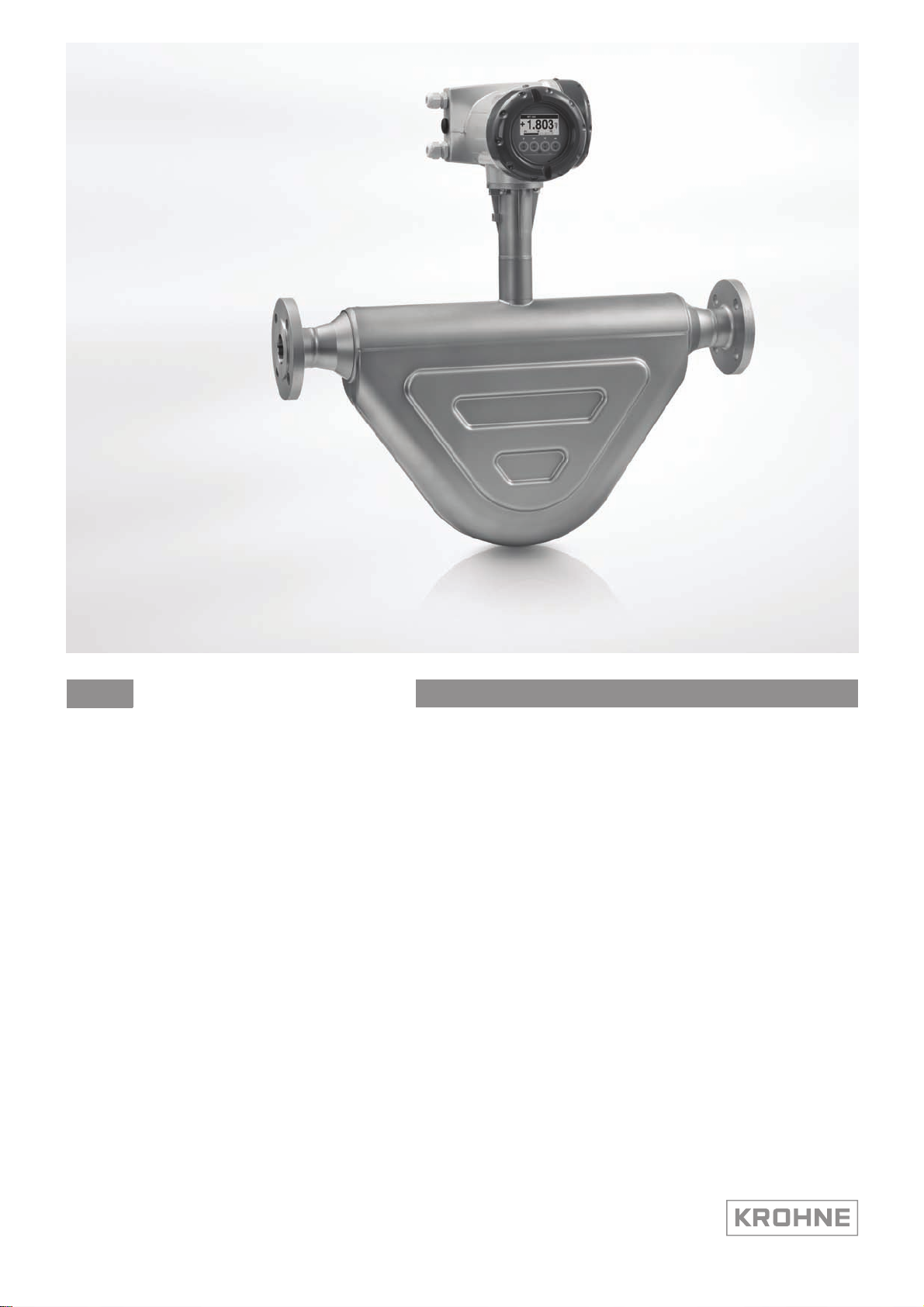
Sensor for mass flow
The documentation is only complete when used in combination with the relevant
documentation for the signal converter.
© KROHNE 07/2014 - 4001894003 - MA OPTIMASS 6000 R03 en
Page 2

: IMPRINT :::::::::::::::::::::::::::::::::::::::
All rights reserved. It is prohibited to reproduce this documentation, or any part thereof, without
the prior written authorisation of KROHNE Messtechnik GmbH.
Subject to change without notice.
Copyright 2014 by
KROHNE Messtechnik GmbH - Ludwig-Krohne-Str. 5 - 47058 Duisburg (Germany)
2
www.krohne.com 07/2014 - 4001894003 - MA OPTIMASS 6000 R03 en
Page 3

OPTIMASS 6000
CONTENTS
1 Safety instructions 5
1.1 Intended use ..................................................................................................................... 5
1.2 CE certification ................................................................................................................. 5
1.3 Associated documents ..................................................................................................... 5
1.4 Insulation case.................................................................................................................. 5
1.5 Pressure Equipment Directive (PED)............................................................................... 6
1.6 Dirty gas............................................................................................................................ 7
1.7 Safety instructions from the manufacturer ..................................................................... 7
1.7.1 Copyright and data protection ................................................................................................ 7
1.7.2 Disclaimer ............................................................................................................................... 7
1.7.3 Product liability and warranty ................................................................................................ 8
1.7.4 Information concerning the documentation........................................................................... 8
1.7.5 Warnings and symbols used................................................................................................... 9
1.8 Safety instructions for the operator................................................................................. 9
2 Device description 10
2.1 Scope of delivery............................................................................................................. 10
2.1.1 Meters with hygienic connections ........................................................................................ 11
2.2 Nameplates .................................................................................................................... 11
2.3 Dual Seal........................................................................................................................ 11
2.4 Temperature differential and thermal shock ................................................................ 12
3 Installation 14
3.1 General notes on installation ......................................................................................... 14
3.2 Storage ........................................................................................................................... 14
3.3 Handling.......................................................................................................................... 15
3.4 Installation conditions ....................................................................................................16
3.4.1 Supporting the meter............................................................................................................ 16
3.4.2 Mounting the meter .............................................................................................................. 17
3.4.3 Gas / liquid build up .............................................................................................................. 18
3.4.4 Side mounting ....................................................................................................................... 18
3.4.5 Cross talk .............................................................................................................................. 19
3.4.6 Flange connections............................................................................................................... 19
3.4.7 Maximum pipework forces (end loadings) ........................................................................... 20
3.4.8 Pipework reducers................................................................................................................ 20
3.4.9 Flexible connections ............................................................................................................. 21
3.4.10 Hygienic installations.......................................................................................................... 21
3.4.11 Heating and insulation ........................................................................................................ 22
3.4.12 Purge ports ......................................................................................................................... 23
3.4.13 Burst discs .......................................................................................................................... 23
3.4.14 Zero calibration................................................................................................................... 24
3.4.15 Sunshades........................................................................................................................... 24
www.krohne.com07/2014 - 4001894003 - MA OPTIMASS 6000 R03 en
3
Page 4

CONTENTS
OPTIMASS 6000
4 Electrical connections 25
4.1 Safety instructions.......................................................................................................... 25
4.2 Electrical and I/O connections ....................................................................................... 25
5 Service 26
5.1 Spare parts availability...................................................................................................26
5.2 Availability of services .................................................................................................... 26
5.3 Returning the device to the manufacturer..................................................................... 26
5.3.1 General information.............................................................................................................. 26
5.3.2 Form (for copying) to accompany a returned device............................................................ 27
5.4 Disposal .......................................................................................................................... 27
6 Technical data 28
6.1 Measuring principle (twin tube) ..................................................................................... 28
6.2 Technical data................................................................................................................. 30
6.3 Measuring accuracy ....................................................................................................... 37
6.4 Guidelines for maximum operating pressure................................................................ 37
6.5 Dimensions and weights ................................................................................................ 42
6.5.1 Flanged versions................................................................................................................... 42
6.5.2 NAMUR dimensions ..............................................................................................................53
6.5.3 Hygienic versions ..................................................................................................................54
6.5.4 Heating jacket version .......................................................................................................... 57
6.5.5 Purge port option .................................................................................................................. 58
6.5.6 Burst discs ............................................................................................................................ 58
6.5.7 Burst disc option ................................................................................................................... 59
4
www.krohne.com 07/2014 - 4001894003 - MA OPTIMASS 6000 R03 en
Page 5

OPTIMASS 6000
1.1 Intended use
This mass flowmeter is designed for the direct measurement of mass flow rate, product density
and product temperature. Indirectly, it also enables the measurement of parameters like total
mass, concentration of dissolved substances and the volume flow. For use in hazardous areas,
special codes and regulations are also applicable and these are specified in a separate
documentation.
1.2 CE certification
CE marking
This device conforms with the following EC directives:
• EMC Directive 2004/108/EC
• ATEX Directive 94/9/EC
• Low Voltage Directive 2006/95/EC
• Pressure Equipment Directive 97/23/EC
SAFETY INSTRUCTIONS 1
The manufacturer declares conformity and the device carries the CE mark.
1.3 Associated documents
This handbook should be read in conjunction with relevant documents in relation to:
• hazardous areas
• communications
• concentration
• corrosion
1.4 Insulation case
On meters fitted with an insulation case, the case will be filled with one of the following
materials:
Cryogenic meters
Cryogenic meters (-200°C...+40°C / -364°F...+104°F)
Cryogenic metersCryogenic meters
Block grade EPS 1112A (Polystyrene) containing flame retardant additive (FRA)
Standard meters
Standard meters (-70°C...+230°C / -94°F...+446°F)
Standard metersStandard meters
Glass mineral wool
www.krohne.com07/2014 - 4001894003 - MA OPTIMASS 6000 R03 en
5
Page 6
1 SAFETY INSTRUCTIONS
High temperature meters
High temperature meters (-50°C...+400°C / -58°F...+752°F)
High temperature metersHigh temperature meters
Silicon dioxide based mineral wool
Do not open the insulation case. Some, or all, of the above materials can cause:
• skin irritation
• throat and lung irritation
• eye irritation
Install the meter so that water cannot get into the insulation case. Water will damage the
insulation material and reduce performance.
1.5 Pressure Equipment Directive (PED)
LEGAL NOTICE!
The Pressure Equipment Directive places legal requirements on both the manufacturer and the
end user. Please read this section carefully!
OPTIMASS 6000
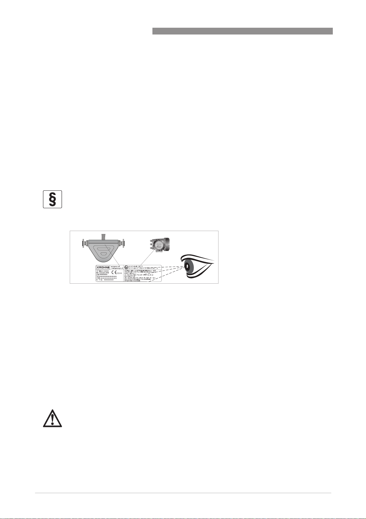
To ensure the PED integrity of the meter, you MUST check that the serial numbers on the
converter nameplate and the sensor nameplate are the same.
To comply with the requirements of the Pressure Equipment Directive (PED) the manufacturer
provides all the relevant technical data in the technical data section of this handbook. Secondary
pressure containment is NOT supplied on this meter.
Tube failure
Where the meter is being used to measure high pressure gasses and / or gasses kept as liquids
by high pressure and / or where there is a risk of tube failure because of the use of corrosive or
erosive fluids, frequent pressure and / or thermal cycling, seismic or other shock loading, the
burst disc option MUST be purchased. For more information, please contact your nearest
representative.
DANGER!
If it is suspected that the primary measuring tube has failed, de-pressurise the meter and
remove it from service as soon as it is safe to do so.
6
www.krohne.com 07/2014 - 4001894003 - MA OPTIMASS 6000 R03 en
Page 7

OPTIMASS 6000
1.6 Dirty gas
Dirty gas is gas that carries sand or other solid particles. Dirty gas causes excessive wear to the
primary measuring tube that can eventually result in complete tube failure. In some situations
tube failure where gas is being measured, can be very dangerous.
DANGER!
If the meter is being used to measure gas and there is a risk that the gas might be dirty, you
must fit a filter upstream of the meter to catch solid particles.
1.7 Safety instructions from the manufacturer
1.7.1 Copyright and data protection
The contents of this document have been created with great care. Nevertheless, we provide no
guarantee that the contents are correct, complete or up-to-date.
The contents and works in this document are subject to copyright. Contributions from third
parties are identified as such. Reproduction, processing, dissemination and any type of use
beyond what is permitted under copyright requires written authorisation from the respective
author and/or the manufacturer.
SAFETY INSTRUCTIONS 1
The manufacturer tries always to observe the copyrights of others, and to draw on works created
in-house or works in the public domain.
The collection of personal data (such as names, street addresses or e-mail addresses) in the
manufacturer's documents is always on a voluntary basis whenever possible. Whenever
feasible, it is always possible to make use of the offerings and services without providing any
personal data.
We draw your attention to the fact that data transmission over the Internet (e.g. when
communicating by e-mail) may involve gaps in security. It is not possible to protect such data
completely against access by third parties.
We hereby expressly prohibit the use of the contact data published as part of our duty to publish
an imprint for the purpose of sending us any advertising or informational materials that we have
not expressly requested.
1.7.2 Disclaimer
The manufacturer will not be liable for any damage of any kind by using its product, including,
but not limited to direct, indirect or incidental and consequential damages.
This disclaimer does not apply in case the manufacturer has acted on purpose or with gross
negligence. In the event any applicable law does not allow such limitations on implied warranties
or the exclusion of limitation of certain damages, you may, if such law applies to you, not be
subject to some or all of the above disclaimer, exclusions or limitations.
Any product purchased from the manufacturer is warranted in accordance with the relevant
product documentation and our Terms and Conditions of Sale.
www.krohne.com07/2014 - 4001894003 - MA OPTIMASS 6000 R03 en
7
Page 8

1 SAFETY INSTRUCTIONS
The manufacturer reserves the right to alter the content of its documents, including this
disclaimer in any way, at any time, for any reason, without prior notification, and will not be liable
in any way for possible consequences of such changes.
1.7.3 Product liability and warranty
The operator shall bear responsibility for the suitability of the device for the specific purpose.
The manufacturer accepts no liability for the consequences of misuse by the operator. Improper
installation and operation of the devices (systems) will cause the warranty to be void. The
respective "Standard Terms and Conditions" which form the basis for the sales contract shall
also apply.
1.7.4 Information concerning the documentation
To prevent any injury to the user or damage to the device it is essential that you read the
information in this document and observe applicable national standards, safety requirements
and accident prevention regulations.
If this document is not in your native language and if you have any problems understanding the
text, we advise you to contact your local office for assistance. The manufacturer can not accept
responsibility for any damage or injury caused by misunderstanding of the information in this
document.
OPTIMASS 6000
This document is provided to help you establish operating conditions, which will permit safe and
efficient use of this device. Special considerations and precautions are also described in the
document, which appear in the form of underneath icons.
8
www.krohne.com 07/2014 - 4001894003 - MA OPTIMASS 6000 R03 en
Page 9
OPTIMASS 6000
1.7.5 Warnings and symbols used
Safety warnings are indicated by the following symbols.
DANGER!
This warning refers to the immediate danger when working with electricity.
DANGER!
This warning refers to the immediate danger of burns caused by heat or hot surfaces.
DANGER!
This warning refers to the immediate danger when using this device in a hazardous atmosphere.
DANGER!
These warnings must be observed without fail. Even partial disregard of this warning can lead to
serious health problems and even death. There is also the risk of seriously damaging the device
or parts of the operator's plant.
SAFETY INSTRUCTIONS 1
WARNING!
Disregarding this safety warning, even if only in part, poses the risk of serious health problems.
There is also the risk of damaging the device or parts of the operator's plant.
CAUTION!
Disregarding these instructions can result in damage to the device or to parts of the operator's
plant.
INFORMATION!
These instructions contain important information for the handling of the device.
LEGAL NOTICE!
This note contains information on statutory directives and standards.
• HANDLING
HANDLING
HANDLINGHANDLING
This symbol designates all instructions for actions to be carried out by the operator in the
specified sequence.
i RESULT
RESULT
RESULTRESULT
This symbol refers to all important consequences of the previous actions.
1.8 Safety instructions for the operator
WARNING!
In general, devices from the manufacturer may only be installed, commissioned, operated and
maintained by properly trained and authorized personnel.
This document is provided to help you establish operating conditions, which will permit safe and
efficient use of this device.
www.krohne.com07/2014 - 4001894003 - MA OPTIMASS 6000 R03 en
9
Page 10
2 DEVICE DESCRIPTION
2.1 Scope of delivery
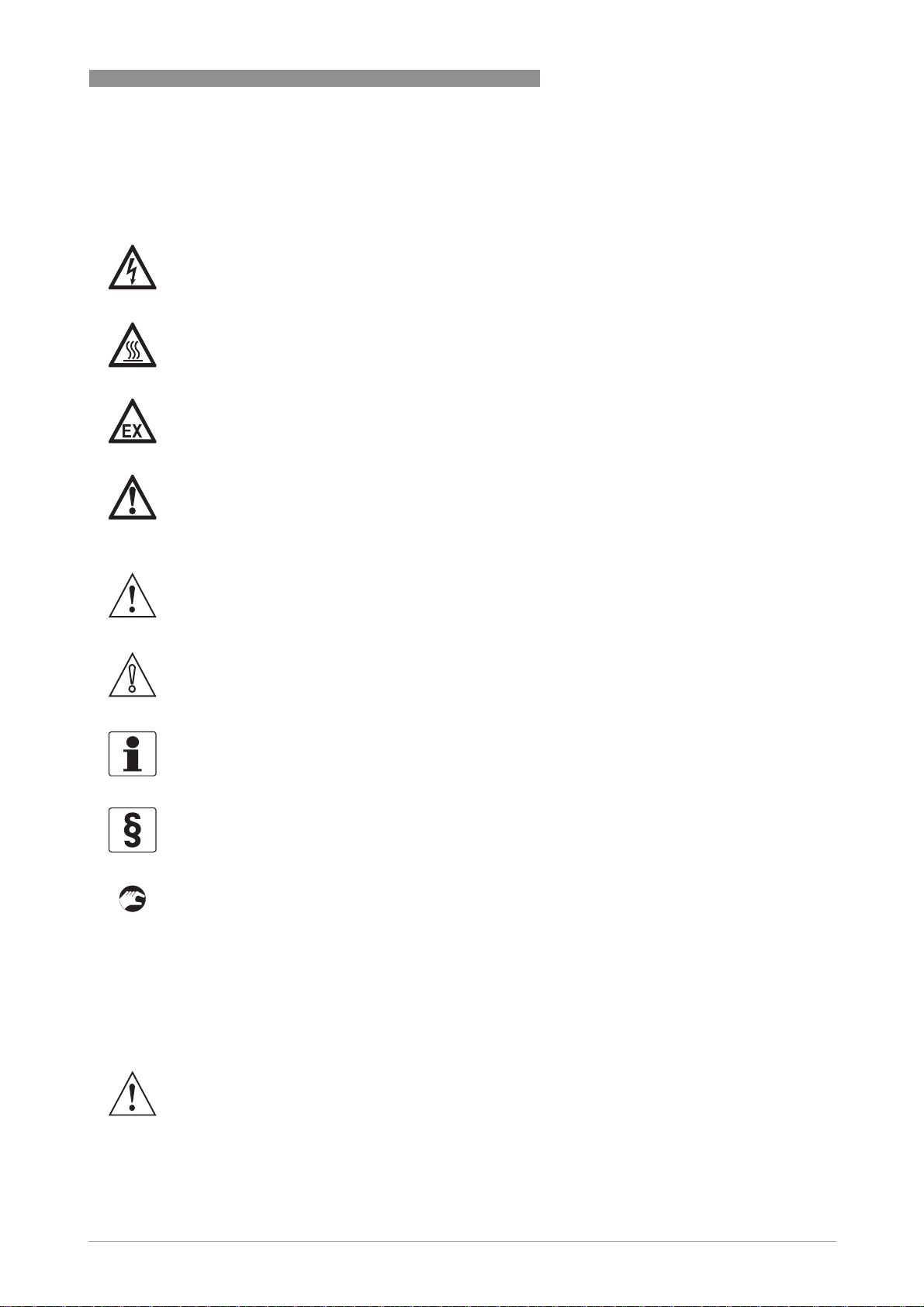
Compact version
1 Mass flowmeter.
2 Carton.
3 Documentation.
4 2.5 mm and 5 mm hex head tools.
5 CD-ROM and calibration certificate.
OPTIMASS 6000
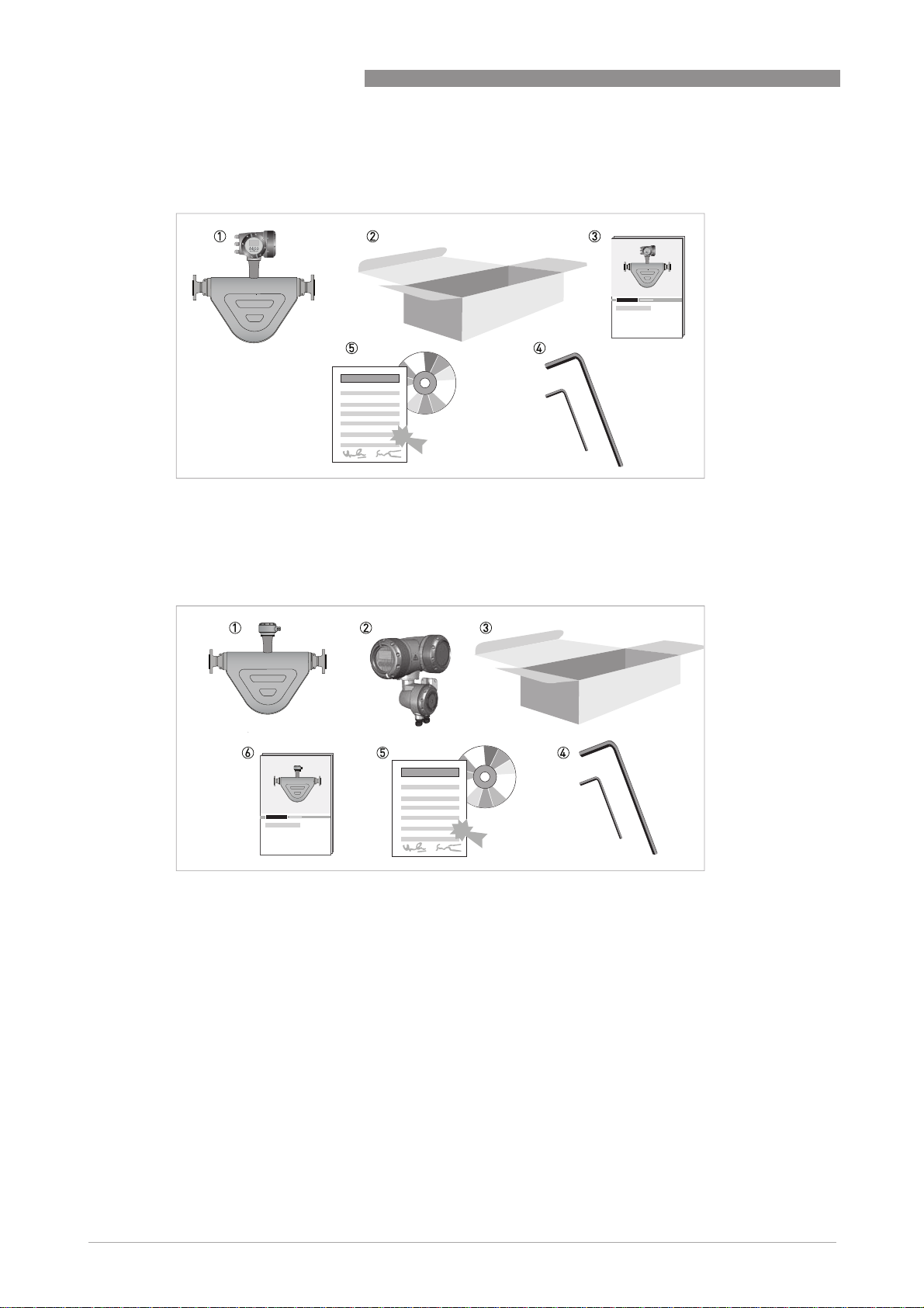
Remote version
1 Mass flowmeter.
2 Converter. This will be either: field (as shown), wall or rack.
3 Carton.
4 2.5 mm and 5 mm hex head tools.
5 CD-ROM and calibration certificate.
6 Documentation.
If any items are missing, please contact the manufacturer.
If your meter has flange connections, the flange specification is stamped on the outer edge of the
flange. Check that the specification on the flange is the same as your order.
10
www.krohne.com 07/2014 - 4001894003 - MA OPTIMASS 6000 R03 en
Page 11
OPTIMASS 6000
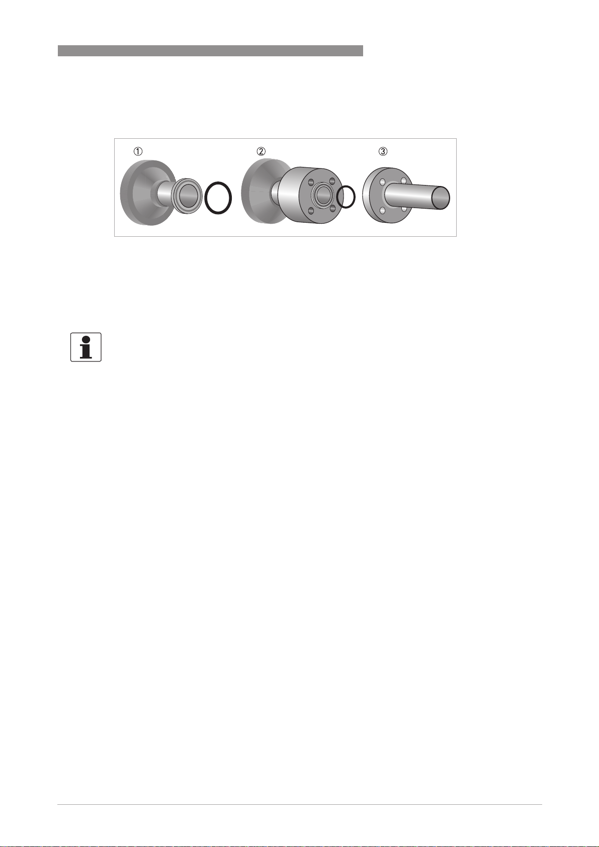
2.1.1 Meters with hygienic connections
1 Fully welded - the O-rings between the meter and the process pipework are not supplied as standard but can be or-
dered.
2 DIN 11864-2 Form A - the O-rings between the Form A and Form B parts of the connection are not supplied as standard
but can be ordered.
3 The 11864-2 Form B is not supplied as part of this connection but it can be ordered.
2.2 Nameplates
INFORMATION!
Look at the device nameplate to ensure that the device is delivered according to your order.
Check for the correct supply voltage printed on the nameplate.
DEVICE DESCRIPTION 2
2.3 Dual Seal
To comply with the requirements of ANSI/ISA -12.27.01-2011 “Requirements for process Sealing
Between electrical systems and Flammable or Combustible process Fluids” a secondary seal is
incorporated into all OPTIMASS / GAS products. If the primary seal fails, the secondary seal will
prevent escaping fluid reaching the electronic compartment.
Pressures and / or temperatures are limited by tube, temperature, connection and Ex limits.
Check the meter nameplates and relevant documentation for full details. On all meters
operating on gas measurement, the casing of the meter is fitted with a burst disc. If the primary
seal (tube) fails leakage will occur from the burst disc. Install the meter so that the burst disc is
pointing away from personnel.
Liquids
Liquids (Example model code: OPTIMASS 6000F S50 - LIQUID
LiquidsLiquids
Pressure and temperature data:
Pressure and temperature data:
Pressure and temperature data:Pressure and temperature data:
OPTIMASS 6000 / 6000F / 6400C -200°C...+230°C and 100...10000 kPa (Stainless Steel)
OPTIMASS 6000 / 6000F / 6400C -50°C...+230°C and 100...20000 kPa (Hastelloy® / duplex)
OPTIMASS 6000 / 6000F - HT -50°C...+400°C and 100...10000 kPa
If the primary seal fails, the casing of the meter will fill with liquid and the meter will stop
working. The meter will notify the operator by displaying the status message "Sensor: Sensor
signal low" on the converter or PLC display. This is an indication that the primary seal (tube) has
failed and the status of the meter should be checked.
As soon as it is safe to do so, de-pressurise the process line and remove the meter. Please
contact customer service for servicing or replacement of the meter.
www.krohne.com07/2014 - 4001894003 - MA OPTIMASS 6000 R03 en
11
Page 12

2 DEVICE DESCRIPTION
INFORMATION!
At high pressures, process fluid may also leak from the meter casing. This is also an indicatioin
that the primary seal has failed.
Meter status:
Meter status:
Meter status:Meter status:
The meter will also display the mesage "Sensor: Sensor signal low" if the measuring tubes are
not completely filled with fluid. For example, if the meter is drained or re/filled.
To check the status of the meter, drain and re/fill with fluid and note the converter or PLC
display. See the relevant section of the converter handbook for a list of status messages and
diagnostics information.
If the meter continues to display the message: "Sensor: Sensor signal low" you MUST assume
that the primary seal (tubes) has failed and the appropriate action MUST be taken.
Gases
Gases (Example model code: OPTIMASS 6000F S50 - GAS)
GasesGases
Pressure / temperature data:
Pressure / temperature data:
Pressure / temperature data:Pressure / temperature data:
OPTIMASS 6000
OPTIMASS 6000 / 6000F / 6400C -200°C...+230°C and 500... 10000 kPa (Stainless Steel)
OPTIMASS 6000 / 6000F / 6400C -50°C...+230°C and 500...20000 kPa (Hastelloy® / duplex)
OPTIMASS 6000F - HT -50°C...+400°C and 500...10000 kPa
Pressures and/or temperatures may be further limited by tube, temperature, connection and Ex
limits. Consult the meter nameplate and relevant documentation for full details.
On all meters operating on gas measurement the casing of the meter is fitted with a burst disc. If
the primary seal (tube/s) fails leakage will occur from the burst disc. Install the meter so that the
burst disc is pointing away from personnel.
Regular maintenance of the burst disc:
Regular maintenance of the burst disc:
Regular maintenance of the burst disc:Regular maintenance of the burst disc:
Carry out regular maintenance checks on burst discs for leakage and/or blockages. On all
OPTIMASS meters, the primary seal is considered to be the measuring tube of the meter. The
materials of construction of the measuring tube/s are described within the relevant sections of
this handbook and the customer’s product and any other fluid flowing through the tube must be
compatible with the material of construction. If failure of the primary seal is suspected then the
process line should be de-pressurised and the meter removed as soon as it is safe to do so.
Please contact customer service for servicing or replacement of the meter.
2.4 Temperature differential and thermal shock
Temperature differential
Temperature differential
Temperature differentialTemperature differential
12
The maximum difference between ambient temperature and process (operating) temperatures
are:
Meter temperature range Maximum temperature differential
-200°C...+40°C / -328°F...+104°F 210°C / 410°F
-70°C...+230°C / -94°F...+446°F
-50°C...+400°C / -58°F...+752°F 380°C / 716°F
www.krohne.com 07/2014 - 4001894003 - MA OPTIMASS 6000 R03 en
Page 13
OPTIMASS 6000
Thermal shock
Thermal shock
Thermal shockThermal shock
Thermal shock occurs when there is a sudden and extreme change (shift) in process
temperature. To prevent thermal shock on this meter, the manufacturer recommends that you
avoid a temperature shift greater than 100°C / 212°F, at a maximum of 40% of the nominal flow
rate.
These limits will give a minimum calculated life span for the meter of 3500 cycles. Thermal
shocking below this temperature will increase the life span of the meter. For more information,
please contact your nearest representative.
Maximum temperature rate rise
Maximum temperature rate rise
Maximum temperature rate riseMaximum temperature rate rise
If the change in temperature (rate rise) is greater than 100°C / 212°F, the temperature rise must
be over a period of time. Calculate the time required for the whole temperature rise using the
table below.
Meter size Temp. rate rise Example
DN 08...50 6°C / 10.8°F per minute 20°C...230°C / 68°F...446°F = 35
DN 80...100 3°C / 5.4°F per minute 20°C...230°C / 68°F...446°F = 70
DEVICE DESCRIPTION 2
minutes
20°C...400°C / 68°F...752°F = 80
minutes
minutes
20°C...400°C / 68°F...752°F = 140
minutes
These limits will provide a minimum calculated life span for the meter of 2000 cycles.
Temperature rises below 100°C / 212°F, or temperature rises over a longer period of time, will
increase the life span of the meter.
CAUTION!
Operation outside these limits may result in shifts in density and mass flow calibration. Repeated
shocking and / or rapid heating, may also result in premature failure of the meter. However,
higher thermal shocks and / or an increased number of cycles are possible at lower working
pressures. For more information, please contact your nearest representative.
www.krohne.com07/2014 - 4001894003 - MA OPTIMASS 6000 R03 en
13
Page 14

3 INSTALLATION
3.1 General notes on installation
INFORMATION!
Inspect the packaging carefully for damages or signs of rough handling. Report damage to the
carrier and to the local office of the manufacturer.
INFORMATION!
Do a check of the packing list to make sure that you have all the elements given in the order.
INFORMATION!
Look at the device nameplate to ensure that the device is delivered according to your order.
Check for the correct supply voltage printed on the nameplate.
3.2 Storage
• Store the device in a dry and dust-free location.
• Avoid direct exposure to the sun.
• Store the device in its original packing.
• Do not allow the ambient temperature to fall below -50°C / -58°F or rise above +85°C /
+185°F.
OPTIMASS 6000
14
www.krohne.com 07/2014 - 4001894003 - MA OPTIMASS 6000 R03 en
Page 15
OPTIMASS 6000
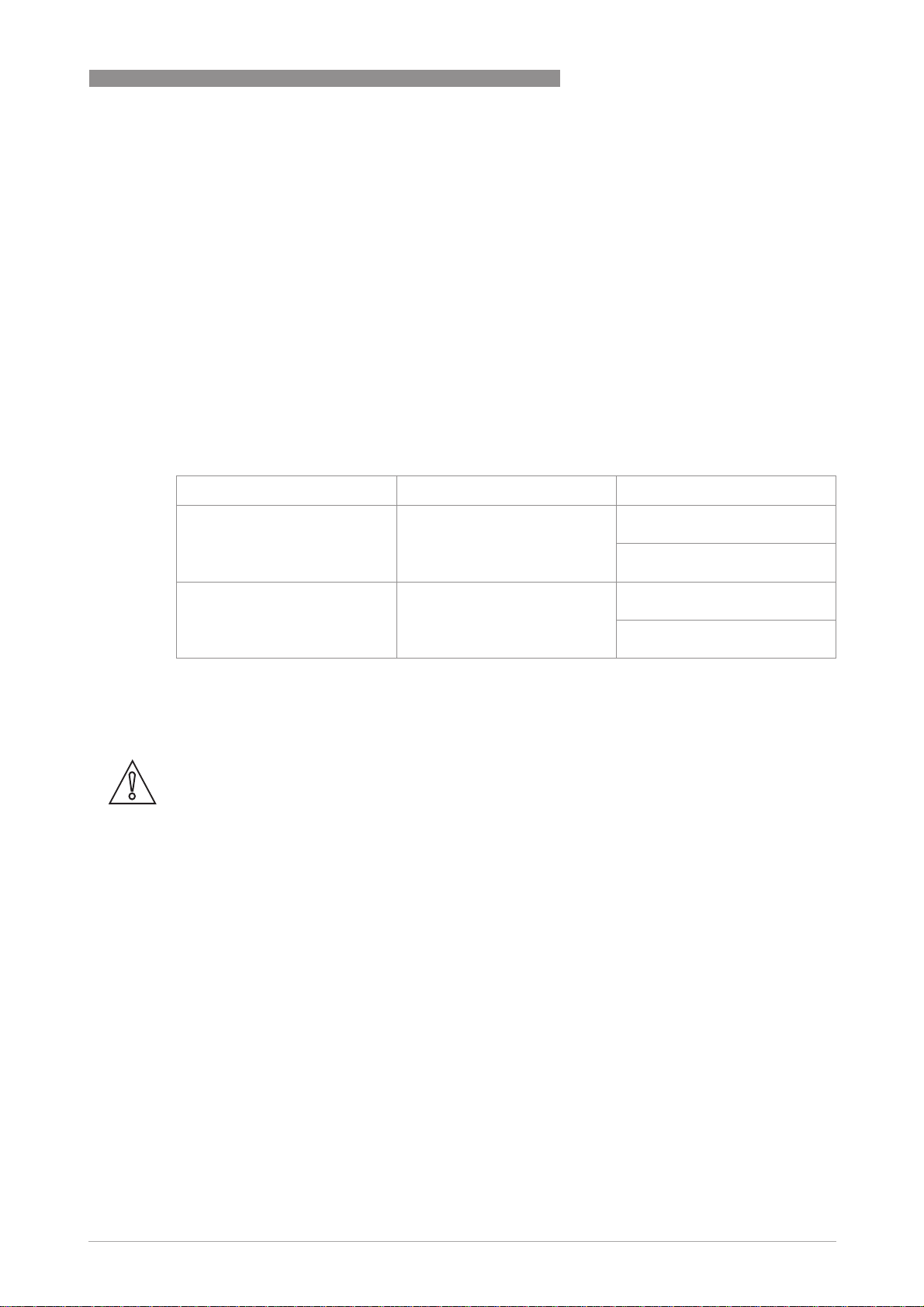
3.3 Handling
INSTALLATION 3
1 Use a well maintained sling to lift the meter by the spigots.
2 DO NOT lift the meter by the converter housing or the electronics stem.
3 DO NOT lift the meter by the meter body.
4 DO NOT lift the meter using the flange bolt holes.
www.krohne.com07/2014 - 4001894003 - MA OPTIMASS 6000 R03 en
15
Page 16
3 INSTALLATION
3.4 Installation conditions
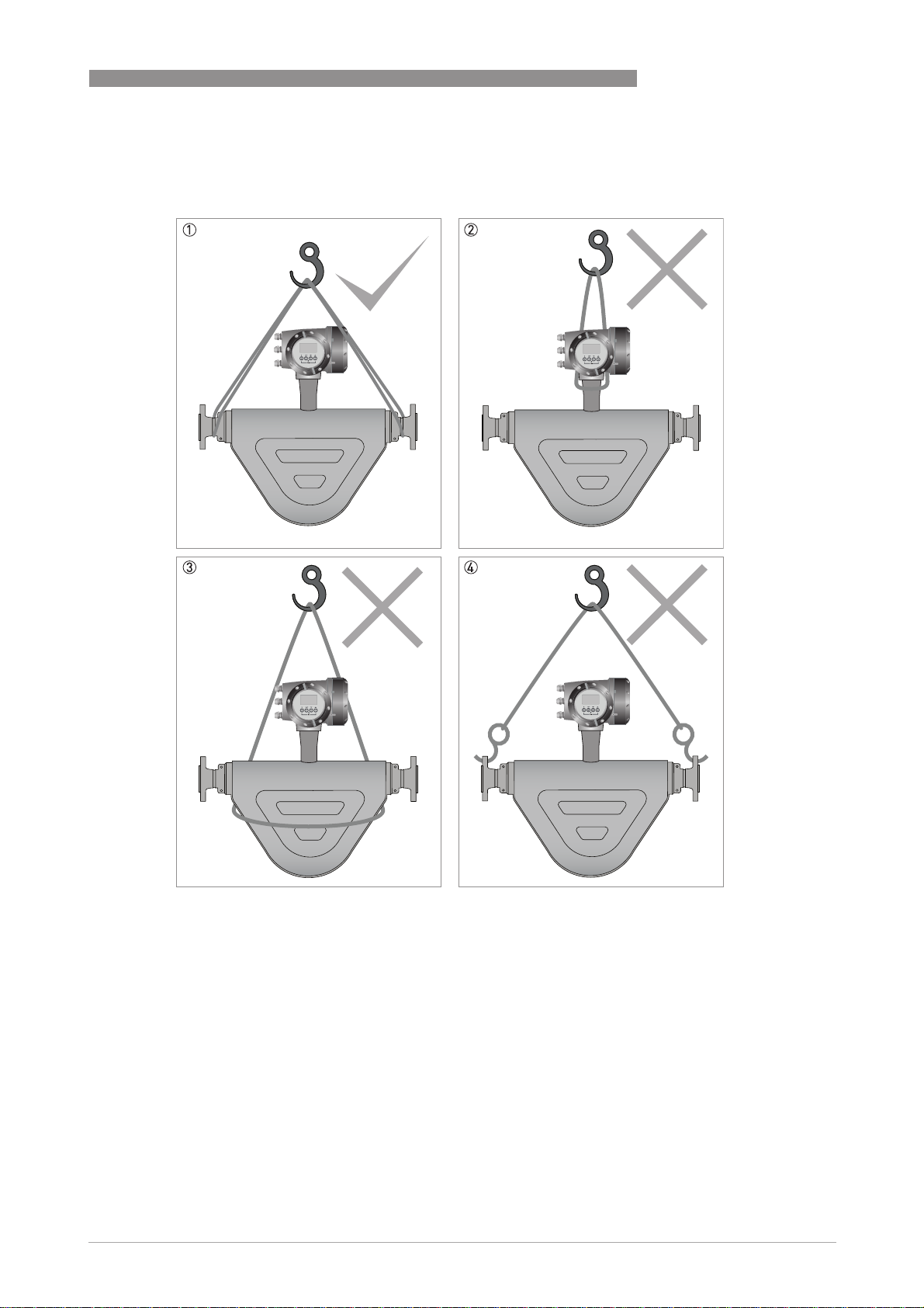
3.4.1 Supporting the meter
OPTIMASS 6000
1 Support the weight of the meter on the process pipework.
2 DO NOT leave a long pipe run between the meter and the support. This can cause damage to the meter, especially on
larger meter sizes.
16
www.krohne.com 07/2014 - 4001894003 - MA OPTIMASS 6000 R03 en
Page 17
OPTIMASS 6000
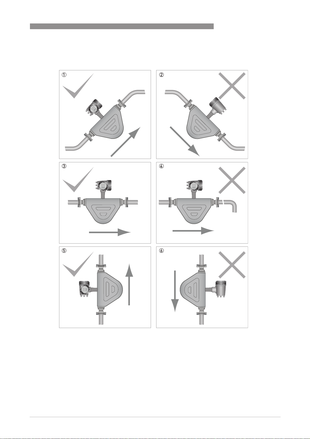
3.4.2 Mounting the meter
Mounting positions
INSTALLATION 3
1 The meter can be mounted at an angle but it is recommended that the flow is uphill.
2 Avoid mounting the meter with the flow running downhill because it can cause siphoning. If the meter has to be mount-
ed with the flow running downhill, install an orifice plate or control valve downstream of the meter to maintain backpressure.
3 Horizontal mounting with flow running left to right.
4 Avoid mounting meter with long vertical runs after the meter as it can cause cavitation. Where the installation includes
a vertical run after the meter, install an orifice plate or control valve downstream to maintain backpressure.
5 The meter can be mounted vertically but it is recommended that the flow is uphill.
6 Avoid mounting the meter vertically with the flow running downhill. This can cause siphoning. If the meter has to be
installed this way, install an orifice plate or control valve downstream to maintain backpressure.
www.krohne.com07/2014 - 4001894003 - MA OPTIMASS 6000 R03 en
17
Page 18
3 INSTALLATION
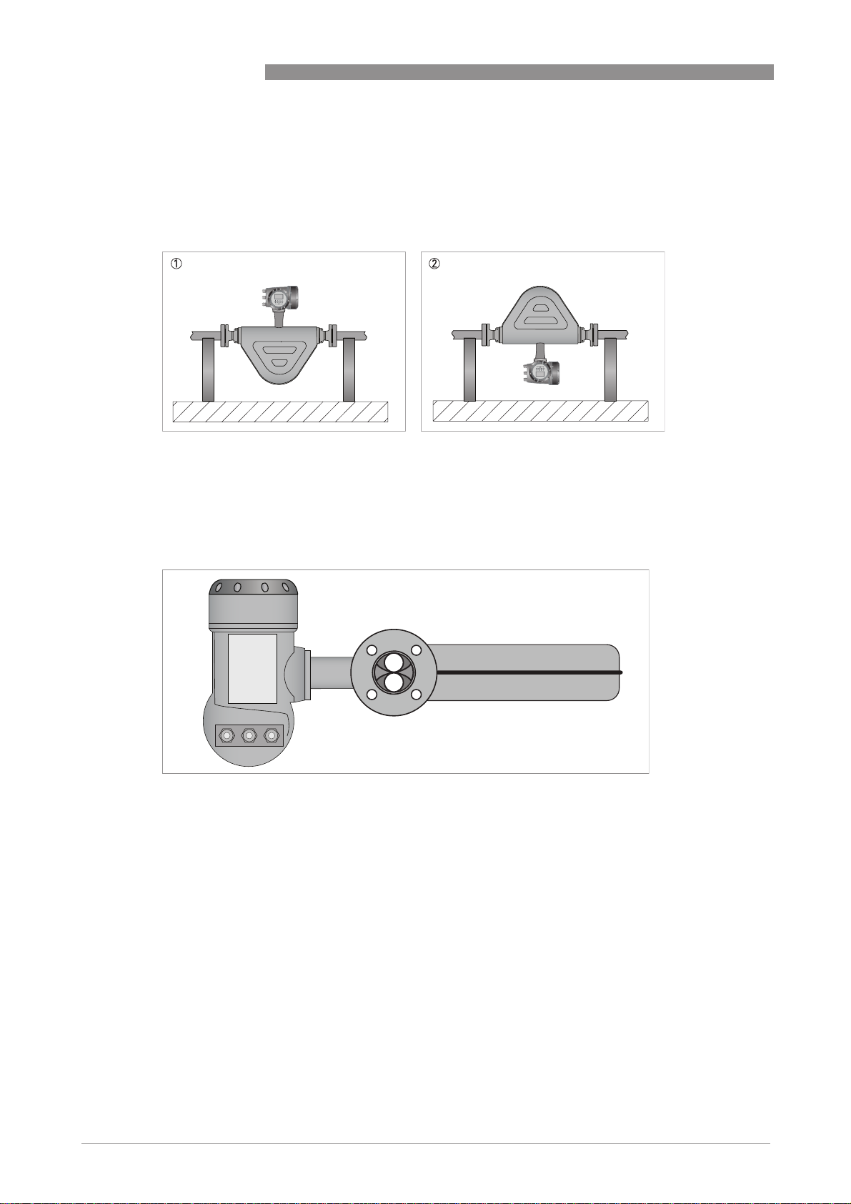
3.4.3 Gas / liquid build up
In certain applications, the design of the meter can cause either gas or liquid to build up in the
measuring tube.
1 Where liquids are being measured, mount the meter as shown. This will prevent gas building up in the measuring tube,
when there is no flow.
2 Where gases are being measured, mount the meter as shown. This will prevent liquids building up in the measuring
tube, when there is no flow.
OPTIMASS 6000
3.4.4 Side mounting
The meter can be installed with the converter (or remote junction box) on the side of the meter
so that the measuring tubes are sitting one above the other. Avoid this method of installation
where there is a two phase process flow, or where the process fluid contains gas. If this situation
cannot be avoided, please contact the manufacturer for advice.
18
www.krohne.com 07/2014 - 4001894003 - MA OPTIMASS 6000 R03 en
Page 19

OPTIMASS 6000
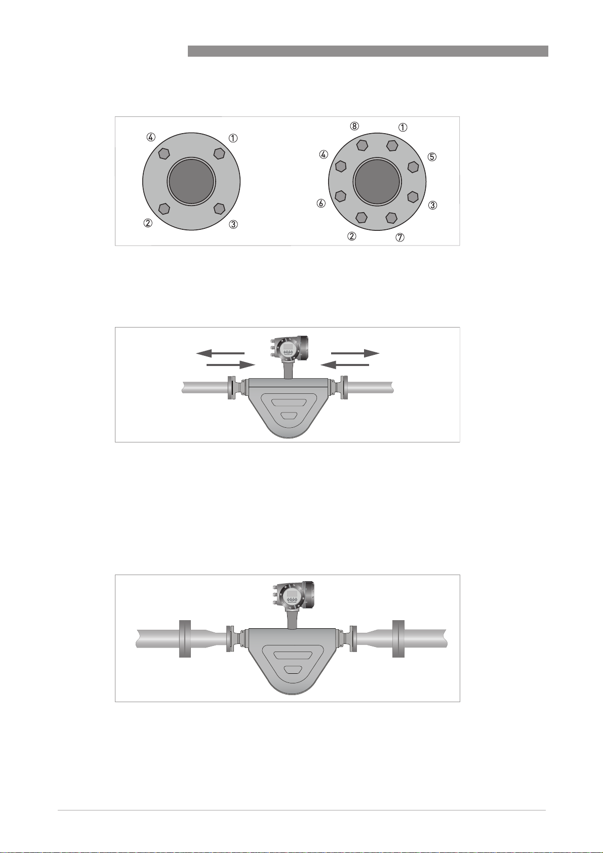
3.4.5 Cross talk
Where more than one meter is being installed, a very high level of immunity to cross talk means
that the meters can be mounted within close proximity to each other. The meters can be
mounted either in series or parallel, as shown.
INFORMATION!
Where the meters are installed in series, it is strongly recommended that the process pipe
diameter remains constant. For more information, please contact the manufacturer.
INSTALLATION 3
3.4.6 Flange connections
Tighten the flange bolts evenly and in turn.
www.krohne.com07/2014 - 4001894003 - MA OPTIMASS 6000 R03 en
19
Page 20
3 INSTALLATION
Use a regular pattern to tighten the bolts evenly
3.4.7 Maximum pipework forces (end loadings)
OPTIMASS 6000
Mass flowmeters have a maximum level of force (negative or positive) that can be applied to the
ends of the meter. Refer to the table below for permitted forces.
Please refer to the table in the technical data section of this Handbook for the maximum end
loadings.
3.4.8 Pipework reducers
Always avoid extreme step changes in pipe size. Use pipework reducers, where there is a large
difference between pipework size and meter flanges.
20
www.krohne.com 07/2014 - 4001894003 - MA OPTIMASS 6000 R03 en
Page 21

OPTIMASS 6000
3.4.9 Flexible connections
Flexible connections can be used but because of the high flow rates associated with large
diameter meters, it is recommended that flexible connections are not used on meters larger
than size 80.
3.4.10 Hygienic installations
INSTALLATION 3
Mounting the meter for hygienic applications
1 Install the meter vertically to allow self draining.
2 DO NOT install the meter horizontally.
Where the meter has been approved by the sanitary requirements of the European Hygienic
Engineering and Design Group, you MUST give consideration to:
• Installation - install the meter at an angle to allow self-draining (see illustration).
• Cleaning fluids - cleaning fluids should flow uphill with a velocity rate greater than
1.5 m/s / 5ft/s. If the process flow is downhill, install a flow restrictor downstream of the
meter. This will make sure that the meter is completely filled with the cleaning fluid.
• Process connections and seals MUST be in accordance with EHEDG documentation.
The manufacturer also recommends that you refer to EHEDG (www.ehedg.org) document
number 8 "HYGIENIC EQUIPMENT DESIGN CRITERIA".
www.krohne.com07/2014 - 4001894003 - MA OPTIMASS 6000 R03 en
21
Page 22

3 INSTALLATION
3.4.11 Heating and insulation
Insulation
Insulation
InsulationInsulation
The meter can be insulated to a maximum depth as shown (A). Do not insulate above this depth
as this will cause the electronics to overheat.
Insulation
OPTIMASS 6000
S08 S10 S15 S25 S50 S80 S100 S150 S200 S250
Dimension A [mm] 100 100 100 100 100 100 100 100 100 100
Dimension A [inches] 3.9 3.9 3.9 3.9 3.9 3.9 3.9 3.9 3.9 3.9
Factory fitted heating jacket
Factory fitted heating jacket
Factory fitted heating jacketFactory fitted heating jacket
If the meter has been ordered with a heating jacket, it will be supplied with DN15 PN40 to EN
1092-1 or 1/2¨ ASME150 flange connections.
22
Figure 3-1: The loop inside the heating jacket, carries the heating medium.
Connecting / using the heating jacket
• Use rigid or reinforced flexible hoses to connect the heating jacket to the heat source.
• The heating jacket / loop material is SS316.
• Suitable heating mediums are steam or hot oil. Avoid the use of heating mediums that can
cause crevice corrosion in Stainless Steel.
www.krohne.com 07/2014 - 4001894003 - MA OPTIMASS 6000 R03 en
Page 23

OPTIMASS 6000
• Where liquid is being used, set up the pipe configuration so that air can be vented from the
system.
• Where steam is being used, set up the pipe configuration so that condensation can be drained
off.
• Gradually heat the jacket to working temperature before flowing the process fluid through
the meter.
CAUTION!
The design of the heating jacket is such that NO end load pressure (negative or positive) can be
applied. The manufacturer recommends that (where possible) flexible hoses are used to connect
to the heat source.
CAUTION!
The maximum heating pressure and temperature for heating jackets is 10 barg at
°
C / 145 psig at 446°F or 5 barg at 400°C / 72.5 psig at 752°F
230
3.4.12 Purge ports
If the meter has been ordered with a purge port, it will be supplied with NPT female connections
which are clearly marked. The connections are sealed with NPT plugs and PTFE tape.
INSTALLATION 3
CAUTION!
DO NOT remove these plugs.
The meter is factory sealed with a dry nitrogen gas fill and if moisture is allowed to enter the
meter casing it will cause damage. The plugs should only be removed to purge the meter casing
in the event that the primary measuring tube fails.
If it is suspected that the primary measuring tube has failed, de-pressurise the meter and
remove it from service, as soon as it is safe to do so.
3.4.13 Burst discs
If the meter has been ordered with a burst disc, it will be supplied with the disc fitted. The failure
pressure of the disc is 10 barg at +20°C / 145 psig at +68°F.
CAUTION!
The fitted burst disc will be suitable for the flow rates and process conditions specified on the
original order. If the process conditions alter in any way, it is recommended that you contact the
manufacturer for advice regarding suitability.
If the process product is hazardous (in any way) it is recommended that an exhaust tube is
connected to the NPT male thread of the burst disc and the pipe routed so that the process
product can be discharged to a safe area. Use a tube with a diameter large enough AND routed in
such a way, so that pressure cannot build up in the meter case.
INFORMATION!
For gas applications, the burst disc must be specified at the time of ordering.
www.krohne.com07/2014 - 4001894003 - MA OPTIMASS 6000 R03 en
23
Page 24

3 INSTALLATION
3.4.14 Zero calibration
The procedure for zero calibration is contained in the converter handbook. However, the
following information should be considered when installing the meter.
Zero calibration
OPTIMASS 6000
1 Where the meter has been installed vertically, install shut-off valves either side of the meter to assist with zero cali-
bration.
2 If the process flow cannot be stopped, install a bypass section for zero calibration.
3.4.15 Sunshades
The meter MUST be protected from strong sunlight.
1 Horizontal installation
2 Vertical installation
24
www.krohne.com 07/2014 - 4001894003 - MA OPTIMASS 6000 R03 en
Page 25

OPTIMASS 6000
4.1 Safety instructions
DANGER!
All work on the electrical connections may only be carried out with the power disconnected. Take
note of the voltage data on the nameplate!
DANGER!
Observe the national regulations for electrical installations!
DANGER!
For devices used in hazardous areas, additional safety notes apply; please refer to the Ex
documentation.
WARNING!
Observe without fail the local occupational health and safety regulations. Any work done on the
electrical components of the measuring device may only be carried out by properly trained
specialists.
ELECTRICAL CONNECTIONS 4
INFORMATION!
Look at the device nameplate to ensure that the device is delivered according to your order.
Check for the correct supply voltage printed on the nameplate.
4.2 Electrical and I/O connections
For information regarding electrical and I/O connections, please refer to the handbook for the
relevant signal converter.
www.krohne.com07/2014 - 4001894003 - MA OPTIMASS 6000 R03 en
25
Page 26

5 SERVICE
5.1 Spare parts availability
The manufacturer adheres to the basic principle that functionally adequate spare parts for each
device or each important accessory part will be kept available for a period of 3 years after
delivery of the last production run for the device.
This regulation only applies to spare parts which are subject to wear and tear under normal
operating conditions.
5.2 Availability of services
The manufacturer offers a range of services to support the customer after expiration of the
warranty. These include repair, maintenance, technical support and training.
INFORMATION!
For more precise information, please contact your local sales office.
5.3 Returning the device to the manufacturer
OPTIMASS 6000
5.3.1 General information
This device has been carefully manufactured and tested. If installed and operated in accordance
with these operating instructions, it will rarely present any problems.
CAUTION!
Should you nevertheless need to return a device for inspection or repair, please pay strict
attention to the following points:
•
Due to statutory regulations on environmental protection and safeguarding the health and
safety of our personnel, manufacturer may only handle, test and repair returned devices that
have been in contact with products without risk to personnel and environment.
•
This means that the manufacturer can only service this device if it is accompanied by the
following certificate (see next section) confirming that the device is safe to handle.
CAUTION!
If the device has been operated with toxic, caustic, flammable or water-endangering products,
you are kindly requested:
•
to check and ensure, if necessary by rinsing or neutralising, that all cavities are free from
such dangerous substances,
•
to enclose a certificate with the device confirming that is safe to handle and stating the
product used.
26
www.krohne.com 07/2014 - 4001894003 - MA OPTIMASS 6000 R03 en
Page 27

OPTIMASS 6000
5.3.2 Form (for copying) to accompany a returned device
Company: Address:
Department: Name:
Tel. no.: Fax no.:
Manufacturer's order no. or serial no.:
The device has been operated with the following medium:
SERVICE 5
This medium is: radioactive
water-hazardous
toxic
caustic
flammable
We checked that all cavities in the device are free from such
substances.
We have flushed out and neutralized all cavities in the
device.
We hereby confirm that there is no risk to persons or the environment through any residual media
contained in the device when it is returned.
Date: Signature:
Stamp:
5.4 Disposal
CAUTION!
Disposal must be carried out in accordance with legislation applicable in your country.
www.krohne.com07/2014 - 4001894003 - MA OPTIMASS 6000 R03 en
27
Page 28

6 TECHNICAL DATA
6.1 Measuring principle (twin tube)
Meter from the side, showing tube layout
OPTIMASS 6000
1 Measuring tubes
2 Drive coil
3 Sensor 1
4 Sensor 2
Static meter not energised and with no flow
1 Measuring tubes
2 Drive coil
3 Sensor 1
4 Sensor 2
A Coriolis twin tube mass flowmeter consists of two measuring tubes 1 a drive coil 2 and two
sensors (3 and 4) that are positioned either side of the drive coil.
28
www.krohne.com 07/2014 - 4001894003 - MA OPTIMASS 6000 R03 en
Page 29

OPTIMASS 6000
Energised meter
1 Measuring tubes
2 Direction of oscilation
3 Sine wave
When the meter is energised, the drive coil vibrates the measuring tubes causing them to
oscillate and produce a sine wave 3. The sine wave is monitored by the two sensors.
Energised meter with process flow
TECHNICAL DATA 6
1 Process flow
2 Sine wave
3 Phase shift
When a fluid or gas passes through the tubes, the coriolis effect causes a phase shift in the sine
wave that is detected by the two sensors. This phase shift is directly proportional to the mass
flow.
Density measurement is made by evaluation of the frequency of vibration and temperature
measurement is made using a Pt500 sensor.
www.krohne.com07/2014 - 4001894003 - MA OPTIMASS 6000 R03 en
29
Page 30

6 TECHNICAL DATA
OPTIMASS 6000
6.2 Technical data
INFORMATION!
•
The following data is provided for general applications. If you require data that is more
relevant to your specific application, please contact us or your local sales office.
•
Additional information (certificates, special tools, software,...) and complete product
documentation can be downloaded free of charge from the website (Download Center).
Measuring system
Measuring principle Coriolis mass flow
Application range Mass flow and density measurement of fluids, gases and solids
Measured values Mass, density, temperature
Calculated values Volume, referred density, concentration, velocity
Sensor model range
Sensor model range
Sensor model rangeSensor model range
Stainless Steel 316L 08...250 Compact / remote 100 barg @ 20°C / 1450 psig @ 68°F, temp. range
Hastelloy® 08...80
Duplex Stainless Steel 100...200 Compact / remote 200 barg @ 20°C / 2900 psig @ 68°F, temp. range
-70°C...+230°C / -94°F...+446°F
Remote only 100 barg @ 20°C / 1450 psig @ 68°F, temp. range
-50°C...+400°C / -58°F...+752°F
Remote only 100 barg @ 20°C / 1450 psig @ 68°F, temp. range
-200°C...+40°C / -364°F...+104°F
Compact / remote 200 barg @ 20°C / 2900 psig @ 68°F, temp. range
-70°C...+230°C / -58°F...+446°F
-50°C...+230°C / -58°F...+446°F
Design
Basic System consists of a measuring sensor and a converter to process the
Features Fully welded maintenance free sensor with twin V-shaped measuring tube
Variants
Variants
VariantsVariants
Compact version Integral converter
Remote version Available with field or wall versions of the converter
Modbus version Sensor with integral electronics. Modbus output for connection to a PLC
output signal
Measuring accuracy
Mass (standard)
Mass (standard)
Mass (standard)Mass (standard)
Liquid (≥ 20:1 of nominal flow rate) ±0.1% of actual measured flow rate
Liquid (< 20:1 of nominal flow rate) ± zero stability (see zero stability below)
Gas ±0.35% of actual measured flow rate + zero stability
Mass (optional)
Mass (optional)
Mass (optional)Mass (optional)
Liquid (≥ 10:1 of nominal flow rate) ±0.05% of actual measured flow rate
Liquid (< 10:1 of nominal flow rate) ± zero stability (see zero stability below)
Repeatability
Repeatability
RepeatabilityRepeatability
Liquid Better than 0.05% plus zero stability (includes the combined effects of
Gas Better than 0.2% plus zero stability (includes the combined effects of
repeatability, linearity and hysteresis)
repeatability, linearity and hysteresis)
30
www.krohne.com 07/2014 - 4001894003 - MA OPTIMASS 6000 R03 en
Page 31

OPTIMASS 6000
Zero stability
Zero stability
Zero stabilityZero stability
TECHNICAL DATA 6
08 < 0.03 kg/h
10 < 0.06 kg/h
15 < 0.19 kg/h
25 < 0.95 kg/h
50 < 1.8 kg/h
80 < 3.9 kg/h
100 < 8.8 kg/h
150 < 16 kg/h
200 < 30 kg/h
250 < 50 kg/h
Reference conditions
Reference conditions
Reference conditionsReference conditions
Product Water
Temperature +20°C / +68°F
Operating pressure 1 barg / 14.5 psig
Effect on sensor zero point caused by a shift in process temperature
Effect on sensor zero point caused by a shift in process temperature
Effect on sensor zero point caused by a shift in process temperatureEffect on sensor zero point caused by a shift in process temperature
All materials sizes 08...10 0.0010% of nominal flow per 1°C / 0.00056% of nominal flow per 1°F
All materials sizes 15...250 0.00075% of nominal flow per 1°C / 0.00042% of nominal flow per 1°F
Pressure effect on mass flow rate
Pressure effect on mass flow rate
Pressure effect on mass flow ratePressure effect on mass flow rate
All materials sizes 08...50 0.005% per 1 barg / 0.00034 % per 1 psig
All materials sizes 80...100 0.0055% per 1 barg / 0.00038 % per 1 psig
All materials sizes 150...250 0.008% per 1 barg / 0.00055 % per 1 psig
Density
Density
DensityDensity
Measuring range
Accuracy
On site calibration
100...3000 kg/m3 / 6...187 lbs/ft
±1 kg/m3 / ±0.06 lbs/ft
3
±0.2 kg/m3 / ±0.012 lbs/ft
3
3
Process temperature effect 0.015 g/l per 1°C / 0.0083 g/l per 1°F
Temperature
Temperature
TemperatureTemperature
Accuracy ± 0.5°C / ±0.9°F (± 0.5% of reading)
Operating conditions
Nominal flow rates
Nominal flow rates (1 barg / 14.5 psig pressure drop)
Nominal flow ratesNominal flow rates
08 600 kg/h / 22 lbs/min
10 1200 kg/h / 44 lbs/min
15 3800 kg/h / 139 lbs/min
25 19000 kg/h / 698 lbs/min
50 35000 kg/h / 1286 lbs/min
80 78000 kg/h / 2866 lbs/min
100 175000 kg/h / 6430 lbs/min
150 320000 kg/h / 11758 lbs/min
200 550000 kg/h / 20209 lbs/min
250 1000000 kg/h / 36743 lbs/min
Assumes operating density 1000 kg/m3 / 62.4 lb/ft
For Hastelloy® meters, assume a pressure drop of 1.15 barg
www.krohne.com07/2014 - 4001894003 - MA OPTIMASS 6000 R03 en
3
31
Page 32

6 TECHNICAL DATA
Maximum flow rates
Maximum flow rates
Maximum flow ratesMaximum flow rates
All meters 150% of nominal flow rate
Ambient temperature
Ambient temperature
Ambient temperatureAmbient temperature
Compact version with Aluminium
converter
Compact version with Stainless Steel
converter
Remote versions Standard temperature range: -40...+65°C / -40…+149°F
Hazardous Area versions Refer to temperature limits
Process temperatures
Process temperatures
Process temperaturesProcess temperatures
Standard temperature range (flange connections)
Safe area -70…+230°C / -94…+446°F
Hazardous area -50…+230°C / -58…+446°F
High temperature range -50…+400°C / -58…+752°F
Cryogenic temperature range -200…+40°C / -328…+104°F
Standard temperature range (hygienic connections)
Safe area -70…+150°C / -94…+302°F
Hazardous area -50…+150°C / -58…+302°F
Nominal pressure at 20
Nominal pressure at 20°C / 68
Nominal pressure at 20Nominal pressure at 20
Measuring tube
Measuring tube SS 316 / 316L Hastelloy® C22 / S31803
Measuring tubeMeasuring tube
FM / PED 97/23/EC -1…100 barg / -14.5…1450 psig -1…200 barg / -14.5…2900 psig
CRN / ASME B31.3 -1…100 barg / -14.5…1450 psig Pending
Outer casing burst pressure
Outer casing burst pressure
Outer casing burst pressureOuter casing burst pressure
08 ≈ 100 barg
10
15
25
50 ≈ 70 barg
80
100 ≈ 10 barg
150
200
250
If the process temperature is higher than 20°C / 68°F, the burst pressure will be lower. For more information please
contact the manufacturer.
Fluid properties
Fluid properties
Fluid propertiesFluid properties
Permissible physical condition Liquids, gases, slurries
Permissible gas content (volume) Contact manufacturer for information.
Permissible solid content (volume) Contact manufacturer for information.
Protection category (acc. to EN 60529) IP 67, NEMA 4X
Installation conditions
Installation conditions
Installation conditionsInstallation conditions
Inlet / outlet runs None required
C / 68°F
C / 68C / 68
F
FF
-40...+65°C / -40…+149°F
-40...+55°C / -40…+131°F
Cryogenic temperature range: -20...+65°C / -4…+149°F
OPTIMASS 6000
32
www.krohne.com 07/2014 - 4001894003 - MA OPTIMASS 6000 R03 en
Page 33

OPTIMASS 6000
TECHNICAL DATA 6
Materials
Stainless Steel (316 / 316L) meter
Stainless Steel (316 / 316L) meter
Stainless Steel (316 / 316L) meterStainless Steel (316 / 316L) meter
Measuring tubes / Flanges Stainless Steel AISI 316 / 316L (1.4401 / 1.4404) dual certified
Spigots Stainless Steel CF3M (1.4409)
Bridge Stainless Steel AISI 304 / 304L (1.4301 / 1.4307) dual certified or AISI 316 /
Outer casing Stainless Steel AISI 316 / 316L (1.4401 / 1.4404) dual certified
Stainless Steel (S31803) meter
Stainless Steel (S31803) meter
Stainless Steel (S31803) meterStainless Steel (S31803) meter
Measuring tubes / Flanges Stainless Steel UNS 31803 (1.4462)
Spigots Stainless Steel J92205 (1.4470)
Bridge Stainless Steel AISI 304 / 304L (1.4301 / 1.4307) dual certified or AISI 316 /
Outer casing Stainless Steel AISI 316 / 316L (1.4401 / 1.4404) dual certified
Hastelloy
Hastelloy® C22 meter
HastelloyHastelloy
Measuring tubes / raised face Hastelloy® C22
(Backing) flanges Stainless Steel AISI 316 / 316L (1.4401 / 1.4404) dual certified
Bridge Stainless Steel AISI 316 / 316L (1.4401 / 1.4404) dual certified
Outer casing Stainless Steel AISI 316L (1.404) dual certified
Heating jacket version
Heating jacket version
Heating jacket versionHeating jacket version
Heating loop and insulation jacket Stainless Steel AISI 316 (1.4401)
All versions
All versions
All versionsAll versions
Junction box (remote version) Die-cast Aluminium (polyurethane coating)
C22 meter
C22 meter C22 meter
316L (1.4401 / 1.4404) dual certified
316L (1.4401 / 1.4404) dual certified
Optional Stainless Steel 316 (1.4401)
Process connections
Flange
Flange
FlangeFlange
DIN (EN 1092-1 2007) DN10…300 / PN16…160
ASME (B616.5) ½...12" / ASME 150…1500
JIS (2220 2001) 10A...300A / 10...20K (10K maximum allowable temperature 300°C / 572°F)
Hygienic (08...50 only)
Hygienic (08...50 only)
Hygienic (08...50 only)Hygienic (08...50 only)
Tri-clover ¾...3"
Tri-clamp DIN 32676 DN15..80
Tri-clamp ISO 2852 1...3"
DIN 11864-2 Form A (female) DN15...80
Male thread DIN 11851 (threaded
sanitary connection)
Male thread SMS 25...76 mm / 1...3"
DN15...80
Electrical connections
Electrical connections For full details, including: power supply, power consumption etc., see
I/O For full details of I/O options, including data streams and protocols, see
technical data for the relevant signal converter.
technical data for the relevant signal converter.
www.krohne.com07/2014 - 4001894003 - MA OPTIMASS 6000 R03 en
33
Page 34

6 TECHNICAL DATA
OPTIMASS 6000
Approvals
Mechanical
Mechanical
MechanicalMechanical
Electromagnetic compatibility (EMC)
acc. to CE
European Pressure Equipment Directive PED 97-23 EC (acc. to EN13445-3)
CRN acc. to ASME B31.3 (pending)
NACE MR0175 / ISO 15156 ("Sulphide Stress Corrosion Cracking Resistant Metalic
ATEX (acc. 94/9/EC)
ATEX (acc. 94/9/EC)
ATEX (acc. 94/9/EC)ATEX (acc. 94/9/EC)
OPTIMASS 6400C non Ex i signal outputs
OPTIMASS 6400C non Ex i signal outputs
OPTIMASS 6400C non Ex i signal outputsOPTIMASS 6400C non Ex i signal outputs
Ex d connection compartment II 1/2 G Ex d ia IIC T6....T1 Ga/Gb
Ex e connection compartment II 1/2 G Ex de ia IIC T6....T1 Ga/Gb
OPTIMASS 6400C Ex i signal outputs
OPTIMASS 6400C Ex i signal outputs
OPTIMASS 6400C Ex i signal outputsOPTIMASS 6400C Ex i signal outputs
Ex d connection compartment II 1/2(1) G Ex d ia [ia Ga] IIC T6....T1 Ga/Gb
Ex e connection compartment II 1/2(1) G Ex de ia [ia Ga] IIC T6....T1 Ga/Gb
OPTIMASS 6000 / 6000F
OPTIMASS 6000 / 6000F II 1 G Ex ia IIC T6...T1 Ga
OPTIMASS 6000 / 6000FOPTIMASS 6000 / 6000F
Namur NE 21/5.95
2004/108/EC (EMC)
2006/95/EC (Low Voltage Directive)
Materials for OIl Field Equipment") and MR0103 ("Materials Resistant to
Sulfide Stress Cracking in Corrosive Petroleum Refining Environments")
II 2 D Ex t IIIC T270°C Db
II 2 D Ex t IIIC T270°C Db
II 2(1) D Ex t [ia Da] IIIC T270°C Db
II 2(1) D Ex t [ia Da] IIIC T270°C Db
II 1 D Ex ia IIIC T270°C Da
II 1 D Ex ia IIIC T440°C Da
ATEX (acc. 94/9/EC) temperature limits
OPTIMASS 6000 / 6000F with or without heating jacket / insulation.
Ambient temp. T
-40...40 -50...40 T6 T80
-40...55 -50...40 T6 T80
-40...65 -50...40 T6 T80
Cryogenic version
Cryogenic version
Cryogenic versionCryogenic version
-20...65 -200...40 T6-T1 T80
OPTIMASS 6400C with aluminium converter housing, with or without heating jacket / insulation
-40...40 -50...40 T6 T80
°C Medium temp. Tm °C Temp. class Max. Surface temp. °C
amb
-50...150 T3 T190
-50...230 T2-T1 T270
-50...150 T3 T190
-50...230 T2-T1 T270
-50...150 T3 T190
-50...230 T2-T1 T270
-50...150 T3 T190
-50...230 T2-T1 T270
34
www.krohne.com 07/2014 - 4001894003 - MA OPTIMASS 6000 R03 en
Page 35

OPTIMASS 6000
-40...50 -50...40 T6 T80
-50...150 T3 T190
-50...230 T2-T1 T270
-40...65 -50...65 T4-T1 T105
Cryogenic version
Cryogenic version
Cryogenic versionCryogenic version
-40...65 -200...40 T6-T1 T80
OPTIMASS 6400C with SS converter housing, with or without heating jacket / insulation.
-40...40 -50...40 T6 T80
-50...150 T3 T190
-50...230 T2-T1 T270
-40...50 -50...40 T6 T80
-50...150 T3 T190
-50...230 T2-T1 T270
-40...60 -50...60 T4-T1 T100
Cryogenic version
Cryogenic version
Cryogenic versionCryogenic version
-25...+60 -200...40 T6-T1 T80
High temperature versions
High temperature versions
High temperature versionsHigh temperature versions
OPTIMASS 6000F - HT with aluminium junction box, heating jacket and insulation
-40...40 -50...40 T6 T80
-50...230 T2 T270
-50...400 T1 T440
-40...55 -50...40 T6 T80
-50...230 T2 T270
-50...400 T1 T440
-40...60 -50...40 T6 T80
-50...230 T2 T270
-50...400 T1 T440
-40...65 -50...350 T1 T390
OPTIMASS 6000F - HT with SS junction box, heating jacket and insulation
-40...40 -50...40 T6 T80
-50...230 T2 T270
-50...400 T1 T440
-40...50 -50...40 T6 T80
-50...230 T2 T270
-50...400 T1 T440
-40...55 -50...40 T6 T80
-50...230 T2 T270
-50...400 T1 T440
-40...60 -50...350 T1 T390
OPTIMASS 6000F - HT with aluminium or SS junction box, insulation but no heating jacket
-40...40 -50...40 T6 T80
-50...230 T2 T270
-50...400 T1 T440
TECHNICAL DATA 6
www.krohne.com07/2014 - 4001894003 - MA OPTIMASS 6000 R03 en
35
Page 36

6 TECHNICAL DATA
-40...55 -50...40 T6 T80
-50...230 T2 T270
-50...400 T1 T440
-40...65 -50...40 T6 T80
-50...230 T2 T270
-50...400 T1 T440
Maximum end loadings (Stainless Steel 316 / 316L)
OPTIMASS 6000
S08 /
S15 S25 S50 S80 S100 S150 S200 S250
S10
Flanges
Flanges
FlangesFlanges
20°C 40 barg 15 kN 25 kN 38 kN 48 kN 99 kN 130 kN 250 kN 300 kN 350 kN
100 barg 12 kN 17 kN 19 kN 15 kN 20 kN 100 kN 150 kN 150 kN 200 kN
230°C 32 barg 7 kN 12 kN 18 kN 25 kN 45 kN 60 kN 150 kN 200 kN 250 kN
60 barg 5 kN 20 kN
400°C 27.4
Hygienic (all connections)
Hygienic (all connections)
Hygienic (all connections)Hygienic (all connections)
150°C 10 barg 5 kN 9 kN 12 kN 12 kN 18 kN N/A N/A N/A N/A
barg
40 barg 4 kN 5 kN 20 kN
5 kN 6 kN 10 kN 12 kN 20 kN 50 kN 80 kN 100 kN 150 kN
Maximum end loadings (Hastelloy® and Stainless Steel UNS S31803)
H08 / H10 H15 H25 H50 H80 D100 D150 D200
Flanges (not including CRN)
Flanges (not including CRN)
Flanges (not including CRN)Flanges (not including CRN)
20°C 200 barg 12 kN 17 kN 19 kN 15 kN 20 kN 100 kN 150 kN
230°C 145 barg 5 kN 20 kN
Flanges (CRN regions)
Flanges (CRN regions)
Flanges (CRN regions)Flanges (CRN regions)
20°C 200 barg
1
230°C 145 barg
2
1 D200 limited to 180 barg at 20°C
2 D100 and D150 limited to 120 barg at 230°C. D200 limited to 110 barg at 230°C
12 kN 17 kN 19 kN 15 kN 20 kN 60 kN 30 kN 10 kN
5 kN 20 kN
36
• DN08...50 (axial) loads have been calculated, based on 316L schedule 40 process pipework,
where un-radiographed butt welds have been used in pipe joints.
• DN80...250 (axial) loads have been calculated, based on 316L schedule 80 process pipework,
where un-radiographed butt welds have been used in pipe joints.
• The loads shown are the maximum permitted static load. If loads are cycling (between
tension and compression) these loads should be reduced. For advice, consult the
manufacturer.
www.krohne.com 07/2014 - 4001894003 - MA OPTIMASS 6000 R03 en
Page 37

OPTIMASS 6000
6.3 Measuring accuracy
TECHNICAL DATA 6
X nominal flow rate [%]
Y measuring error [%]
Measuring error
The measuring error is obtained from the combined effects of accuracy and zero stability.
Reference conditions
Product Water
Temperature +20°C / +68°F
Operating pressure 1 barg / 14.5 psig
6.4 Guidelines for maximum operating pressure
Notes:
• Ensure that the meter is used within its operating limits
• All hygienic process connections have a maximum operating rating of 10 barg
at 150°C / 145 psig at 302°F
www.krohne.com07/2014 - 4001894003 - MA OPTIMASS 6000 R03 en
37
Page 38

6 TECHNICAL DATA
Pressure / temperature de-rating (metric) for meters with SS 316 measuring tubes.
Pressure / temperature de-rating (metric) for meters with SS 316 measuring tubes.
Pressure / temperature de-rating (metric) for meters with SS 316 measuring tubes. Pressure / temperature de-rating (metric) for meters with SS 316 measuring tubes.
Standard temperature range.
Standard temperature range.
Standard temperature range.Standard temperature range.
OPTIMASS 6000
2
X temperature [°C]
Y pressure [barg]
1 Measuring tube PED certification
2 Hygienic connection
Pressure / temperature de-rating (imperial) for meters with SS 316 measuring tubes.
Pressure / temperature de-rating (imperial) for meters with SS 316 measuring tubes.
Pressure / temperature de-rating (imperial) for meters with SS 316 measuring tubes. Pressure / temperature de-rating (imperial) for meters with SS 316 measuring tubes.
Standard temperature range.
Standard temperature range.
Standard temperature range.Standard temperature range.
2
38
X temperature [°F]
Y pressure [psig]
1 Measuring Tube PED certification
2 Hygienic connection
www.krohne.com 07/2014 - 4001894003 - MA OPTIMASS 6000 R03 en
Page 39

OPTIMASS 6000
Pressure / temperature de-rating (metric) for meters with SS 316, PED certified
Pressure / temperature de-rating (metric) for meters with SS 316, PED certified
Pressure / temperature de-rating (metric) for meters with SS 316, PED certified Pressure / temperature de-rating (metric) for meters with SS 316, PED certified
measuring tubes. High temperature range.
measuring tubes. High temperature range.
measuring tubes. High temperature range.measuring tubes. High temperature range.
TECHNICAL DATA 6
X temperature [°C]
Y pressure [barg]
Pressure / temperature de-rating (imperial) for meters with SS 316, PED certified
Pressure / temperature de-rating (imperial) for meters with SS 316, PED certified
Pressure / temperature de-rating (imperial) for meters with SS 316, PED certified Pressure / temperature de-rating (imperial) for meters with SS 316, PED certified
measuring tubes. High temperature range.
measuring tubes. High temperature range.
measuring tubes. High temperature range.measuring tubes. High temperature range.
X temperature [°F]
Y pressure [psig]
www.krohne.com07/2014 - 4001894003 - MA OPTIMASS 6000 R03 en
39
Page 40

6 TECHNICAL DATA
Pressure / temperature de-rating (metric) for meters with SS 31803 and Hastelloy
Pressure / temperature de-rating (metric) for meters with SS 31803 and Hastelloy®
Pressure / temperature de-rating (metric) for meters with SS 31803 and HastelloyPressure / temperature de-rating (metric) for meters with SS 31803 and Hastelloy
C22, PED certified measuring tubes. Standard temperature range
C22, PED certified measuring tubes. Standard temperature range
C22, PED certified measuring tubes. Standard temperature rangeC22, PED certified measuring tubes. Standard temperature range
OPTIMASS 6000
X temperature [°C]
Y pressure [barg]
1 PED / CRN H08...80
2 CRN D100...150
3 CRN D200
Pressure / temperature de-rating (imperial) for meters with SS 31803 and Hastelloy
Pressure / temperature de-rating (imperial) for meters with SS 31803 and Hastelloy®
Pressure / temperature de-rating (imperial) for meters with SS 31803 and HastelloyPressure / temperature de-rating (imperial) for meters with SS 31803 and Hastelloy
C22, PED certified measuring tubes. Standard temperature range.
C22, PED certified measuring tubes. Standard temperature range.
C22, PED certified measuring tubes. Standard temperature range.C22, PED certified measuring tubes. Standard temperature range.
40
X temperature [°F]
Y pressure [psig]
1 PED / CRN H08...80
2 CRN D100...150
3 CRN D200
www.krohne.com 07/2014 - 4001894003 - MA OPTIMASS 6000 R03 en
Page 41

OPTIMASS 6000
Pressure / temperature de-rating (metric) for meters with SS 316, PED certified
Pressure / temperature de-rating (metric) for meters with SS 316, PED certified
Pressure / temperature de-rating (metric) for meters with SS 316, PED certified Pressure / temperature de-rating (metric) for meters with SS 316, PED certified
measuring tubes. Cryogenic temperature range.
measuring tubes. Cryogenic temperature range.
measuring tubes. Cryogenic temperature range.measuring tubes. Cryogenic temperature range.
TECHNICAL DATA 6
X temperature [°C]
Y pressure [barg]
Pressure / temperature de-rating (imperial) for meters with SS 316 measuring tubes
Pressure / temperature de-rating (imperial) for meters with SS 316 measuring tubes
Pressure / temperature de-rating (imperial) for meters with SS 316 measuring tubes Pressure / temperature de-rating (imperial) for meters with SS 316 measuring tubes
PED certified. Cryogenic temperature range.
PED certified. Cryogenic temperature range.
PED certified. Cryogenic temperature range.PED certified. Cryogenic temperature range.
X temperature [°F]
Y pressure [psig]
Flanges
• DIN flange ratings are based on EN 1092-1 2007 table G.4.1 material group 14EO
• ASME flange ratings are based on ASME B16.5 2003 table 2 material group 2.2
• JIS flange ratings are based on JIS 2220: 2001 table 1 division 1 material group 022a
• JIS 10K flanges are limited to a maximum temperature of 300°C / 572°F
www.krohne.com07/2014 - 4001894003 - MA OPTIMASS 6000 R03 en
41
Page 42

6 TECHNICAL DATA
Notes
• The maximum operating pressure will be either the flange rating or the measuring tube
rating, WHICHEVER IS THE LOWER!
• The manufacturer recommends that the seals are replaced at regular intervals. This will
maintain the hygienic integrity of the connection.
WHICHEVER IS THE LOWER!
WHICHEVER IS THE LOWER!WHICHEVER IS THE LOWER!
6.5 Dimensions and weights
6.5.1 Flanged versions
Meter weights
S08 S10 S15 S25 S50 S80 S100 S150 S200 S250
OPTIMASS 6000
kg
Aluminium
(compact)
Stainless Steel
(compact)
Aluminium
(remote)
Stainless Steel
(remote)
Heating jacket add 3.1 4.5 7 7.9 12.7 15.7 27.6 N/A
9.3 10.1 12.9 23.5 29.4 58.9 94.3 193.6 443.6 911.2
15.2 16 18.8 29.4 35.3 64.8 100.2 199.5 449.5 917.1
5.8 6.6 9.4 19.9 25.9 55.4 90.8 190.1 440 907.6
6.6 7.3 10.2 20.7 26.6 56.1 91.5 191.5 440.8 908.4
lbs
S08 S10 S15 S25 S50 S80 S100 S150 S200 S250
Aluminium
(compact)
Stainless Steel
(compact)
Aluminium
(remote)
Stainless Steel
(remote)
Heating jacket add 6.8 9.9 15.4 17.4 28 34.6 60.8 N/A
20.5 22.3 28.4 51.8 64.8 129.8 207.9 426.8 978 2008.8
33.5 35.3 41.4 64.8 77.8 142.9 220.9 440.7 991 2021.9
12.8 14.5 20.7 43.9 57.1 122.1 200.2 419.1 970 2001
14.55 16.1 22.5 45.6 58.6 123.7 201.7 422.2 971.8 2002.7
42
The weights shown are for meters fitted with PN40 flanges. Smaller or larger flange sizes will
affect the overall weight. For further information, please contact the manufacturer.
www.krohne.com 07/2014 - 4001894003 - MA OPTIMASS 6000 R03 en
Page 43

OPTIMASS 6000
Meter dimensions
TECHNICAL DATA 6
1 Compact version
2 Remote version
General dimensions
mm
S08 S10 S15 S25 S50 S80 S100 S150 S200 S250
A ±3 156 186 282 326 411 547 555 675 805
C 123.5
D 137
E1 ±3 (compact) 375 376 393 428 455 480 522 598
E2 ±3 (remote 250°C) 295 296 316 348 375 400 442 518
E2 ±3 (remote 400°C) 335 336 353 388 415 440 482 558
F ±2 81 118 130 188 243 275 355 508
inches
S08 S10 S15 S25 S50 S80 S100 S150 S200 S250
A ±0.11 6.14 7.3 11.1 12.8 16.2 21.5 21.8 26.6 31.7
C 4.9
D 5.4
E1 ±0.12 (compact) 14.8 14.8 15.5 16.8 17.9 18.9 20.5 23.5
E2 ±0.12 (remote 482°F) 11.6 11.6 12.4 13.7 14.8 15.7 17.4 20.4
E2 ±0.12 (remote 752°F) 13.2 13.2 13.9 15.3 16.3 17.3 19 22
F ±0.08 3.2 4.6 5.1 7.4 9.6 10.8 14 20
www.krohne.com07/2014 - 4001894003 - MA OPTIMASS 6000 R03 en
43
Page 44

6 TECHNICAL DATA
OPTIMASS 6000
Dimension B for meters with Stainless Steel measuring tubes
mm (±5)
S08 S10 S15 S25 S50 S80 S100 S150 S200 S250
PN16
PN16
PN16PN16
DN80 - - - - - - 970 - - -
DN100 - - - - - - 1000 1154 - -
DN150 - - - - - - - 1200 1572 -
DN200 - - - - - - - - 1586 -
DN250 - - - - - - - - - 2100
DN300 - - - - - - - - - 2026
PN40
PN40
PN40PN40
DN10 335 347 - - - - - - - -
DN15 341 353 510 - - - - - - -
DN25 - - 514 600 - - - - - -
DN40 - - - 610 709 - - - - -
DN50 - - - - 715 895 - - - -
DN80 - - - - - 915 986 - - -
DN100 - - - - - - 1000 1180 - -
DN150 - - - - - - - 1200 1612 -
DN200 - - - - - - - - 1638 -
DN250 - - - - - - - - - 2080
DN300 - - - - - - - - - 2100
PN63
PN63
PN63PN63
DN50 - - - - 743 923 - - - -
DN80 - - - - - 943 1014 - - -
DN100 - - - - - - 1026 1206 - -
DN150 - - - - - - - 1240 1652 -
DN200 - - - - - - - - 1682 -
DN250 - - - - - - - - - 2120
DN300 - - - - - - - - - 2150
PN100
PN100
PN100PN100
DN10 355 367 - - - - - - - -
DN15 355 367 524 - - - - - - -
DN25 - - 550 636 - - - - - -
DN40 - - - 644 743 - - - - -
DN50 - - - - 755 935 - - - -
DN80 - - - - - 955 1026 - - -
DN100 - - - - - - 1050 1230 - -
DN150 - - - - - - - 1280 1692 -
DN200 - - - - - - - - 1722 -
DN250 - - - - - - - - - 2184
DN300 - - - - - - - - - 2210
44
www.krohne.com 07/2014 - 4001894003 - MA OPTIMASS 6000 R03 en
Page 45

OPTIMASS 6000
TECHNICAL DATA 6
mm (±5)
S08 S10 S15 S25 S50 S80 S100 S150 S200 S250
ASME 150
ASME 150
ASME 150ASME 150
½¨ 361 373 530 - - - - - - -
¾¨ - - 540 - - - - - - -
1¨ - - 546 632 - - - - - 1½¨ - - - 644 743 - - - - 2¨ - - - - 747 926 - - - 3¨ - - - - - 939 1010 - - 4¨ - - - - - - 1022 1202 - 6¨ - - - - - - - 1228 1640 8¨ - - - - - - - - 1666 10¨ - - - - - - - - - 2074
12¨ - - - - - - - - - 2100
ASME 300
ASME 300
ASME 300ASME 300
½¨ 371 383 540 - - - - - - -
¾¨ - - 550 - - - - - - -
1¨ - - 558 644 - - - - - 1½¨ - - - 658 757 - - - - 2¨ - - - - 759 939 - - - 3¨ - - - - - 957 1028 - - 4¨ - - - - - - 1042 1222 - 6¨ - - - - - - - 1246 1658 8¨ - - - - - - - - 1686 10¨ - - - - - - - - - 2106
12¨ - - - - - - - - - 2132
ASME 600
ASME 600
ASME 600ASME 600
½¨ 383 395 552 - - - - - - -
¾¨ - - 562 - - - - - - -
1¨ - - 572 658 - - - - - 1½¨ - - - 674 773 - - - - 2¨ - - - - 779 959 - - - 3¨ - - - - - 977 1048 - - 4¨ - - - - - - 1086 1266 - 6¨ - - - - - - - 1298 1710 8¨ - - - - - - - - 1742 10¨ - - - - - - - - - 2186
12¨ - - - - - - - - - 2194
JIS 10K
JIS 10K
JIS 10KJIS 10K
50A - - - - 715 895 - - - -
80A - - - - - 915 986 - - -
100A - - - - - - 1022 1202 - -
150A - - - - - - - 1202 1652 -
www.krohne.com07/2014 - 4001894003 - MA OPTIMASS 6000 R03 en
45
Page 46

6 TECHNICAL DATA
OPTIMASS 6000
mm (±5)
S08 S10 S15 S25 S50 S80 S100 S150 S200 S250
200A - - - - - - - - 1666 -
250A - - - - - - - - - 2106
300A - - - - - - - - - 2124
JIS 20K
JIS 20K
JIS 20KJIS 20K
10A 341 353 - - - - - - - -
15A 341 353 510 - - - - - - -
25A - - 514 600 - - - - - -
40A - - - 610 709 - - - - -
50A - - - - 715 895 - - - -
80A - - - - - 915 986 - - -
100A - - - - - - 1022 1240 - -
150A - - - - - - - 1240 1652 -
200A - - - - - - - - 1666 -
250A - - - - - - - - - 2106
300A - - - - - - - - - 2124
inches (±0.2)
S08 S10 S15 S25 S50 S80 S100 S150 S200 S250
PN16
PN16
PN16PN16
DN80 - - - - - - 38.2 - - -
DN100 - - - - - - 39.3 45.4 - -
DN150 - - - - - - - 47.2 61.9 -
DN200 - - - - - - - - 62.4 -
DN250 - - - - - - - - - 82.7
DN300 - - - - - - - - - 79.8
PN40
PN40
PN40PN40
DN10 13.2 13.7 - - - - - - - -
DN15 13.4 13.9 20.1 - - - - - - -
DN25 - - 20.2 23.6 - - - - - -
DN40 - - - 24 27.9 - - - - -
DN50 - - - - 28.1 35.2 - - - -
DN80 - - - - - 36 38.8 - - -
DN100 - - - - - - 39.4 46.4 - -
DN150 - - - - - - - 47.2 63.5 -
DN200 - - - - - - - - 64.5 -
DN250 - - - - - - - - - 81.9
DN300 - - - - - - - - - 82.7
PN63
PN63
PN63PN63
DN50 - - - - 29.2 36.3 - - - -
DN80 - - - - - 37.1 39.9 - - -
46
www.krohne.com 07/2014 - 4001894003 - MA OPTIMASS 6000 R03 en
Page 47

OPTIMASS 6000
TECHNICAL DATA 6
inches (±0.2)
S08 S10 S15 S25 S50 S80 S100 S150 S200 S250
DN100 - - - - - - 40.4 47.5 - -
DN150 - - - - - - - 48.8 65 -
DN200 - - - - - - - - 66.2 -
DN250 - - - - - - - - - 83.5
DN300 - - - - - - - - - 84.6
PN100
PN100
PN100PN100
DN10 14 14.4 - - - - - - - -
DN15 14 14.4 20.6 - - - - - - -
DN25 - - 21.6 25 - - - - - -
DN40 - - - 25.3 29.2 - - - - -
DN50 - - - - 29.7 36.8 - - - -
DN80 - - - - - 37.6 40.4 - - -
DN100 - - - - - - 41.3 48.4 - -
DN150 - - - - - - - 50.4 66.6 -
DN200 - - - - - - - - 67.8 -
DN250 - - - - - - - - - 85.9
DN300 - - - - - - - - - 87
ASME 150
ASME 150
ASME 150ASME 150
½¨ 14.2 14.7 20.9 - - - - - - -
¾¨ - - 21.2 - - - - - - -
1¨ - - 21.5 24.9 - - - - - 1½¨ - - - 25.3 29.2 - - - - 2¨ - - - - 29.4 36.5 - - - 3¨ - - - - - 37 39.8 - - 4¨ - - - - - - 40.2 47.3 - 6¨ - - - - - - - 48.3 64.6 8¨ - - - - - - - - 65.6 10¨ - - - - - - - - - 81.6
12¨ - - - - - - - - - 82.7
ASME 300
ASME 300
ASME 300ASME 300
½¨ 14.6 15.1 21.2 - - - - - - -
¾¨ - - 21.6 - - - - - - -
1¨ - - 22 25.3 - - - - - 1½¨ - - - 25.9 29.8 - - - - 2¨ - - - - 30 37 - - - 3¨ - - - - - 37.7 40.5 - - 4¨ - - - - - - 41 48.1 - 6¨ - - - - - - - 49 65.3 8¨ - - - - - - - - 66.4 10¨ - - - - - - - - - 82.9
12¨ - - - - - - - - - 83.9
www.krohne.com07/2014 - 4001894003 - MA OPTIMASS 6000 R03 en
47
Page 48

6 TECHNICAL DATA
OPTIMASS 6000
inches (±0.2)
S08 S10 S15 S25 S50 S80 S100 S150 S200 S250
ASME 600
ASME 600
ASME 600ASME 600
½¨ 15.1 15.5 21.7 - - - - - - -
¾¨ - - 22.1 - - - - - - -
1¨ - - 22.5 25.9 - - - - - 1½¨ - - - 26.5 30.4 - - - - 2¨ - - - - 30.7 37.7 - - - 3¨ - - - - - 38.5 41.2 - - 4¨ - - - - - - 42.8 49.8 - 6¨ - - - - - - - 51.1 67.3 8¨ - - - - - - - - 68.6 10¨ - - - - - - - - - 86
12¨ - - - - - - - - - 86.4
JIS 10K
JIS 10K
JIS 10KJIS 10K
50A - - - - 28.2 35.2 - - - -
80A - - - - - 36 38.8 - - -
100A - - - - - - 40.2 47.3 - -
150A - - - - - - - 47.3 65 -
200A - - - - - - - - 65.5 -
250A - - - - - - - - - 82.9
300A - - - - - - - - - 83.6
JIS 20K
JIS 20K
JIS 20KJIS 20K
10A 13.4 13.9 - - - - - - - -
15A 13.4 13.9 20 - - - - - - -
25A - - 20.2 23.6 - - - - - -
40A - - - 24 27.9 - - - - -
50A - - - - 28.2 35.2 - - - -
80A - - - - - 36 38.8 - - -
100A - - - - - - 40.2 48.8 - -
150A - - - - - - - 48.8 65 -
200A - - - - - - - - 62.6 -
250A - - - - - - - - - 82.9
300A - - - - - - - - - 83.6
Dimension B for meters with Hastelloy® and Stainless Steel (UNS S31803) measuring tubes
mm
H08 H10 H15 H25 H50 H80 D100 D150 D200
PN40
PN40
PN40PN40
DN15 328 353 - - - - - - -
DN25 - - 510 - - - - - -
DN40 - - - 600 - - - - -
DN50 - - - - 715 - - - -
48
www.krohne.com 07/2014 - 4001894003 - MA OPTIMASS 6000 R03 en
Page 49

OPTIMASS 6000
TECHNICAL DATA 6
mm
H08 H10 H15 H25 H50 H80 D100 D150 D200
DN80 - - - - - 915 - - -
PN63
PN63
PN63PN63
DN50 - - - - 715 - - - -
DN80 - - - - - 915 - - -
PN100
PN100
PN100PN100
DN15 328 353 - - - - - - -
DN25 - - 510 - - - - - -
DN40 - - - 600 - - - - -
DN50 - - - - 715 - - - -
DN80 - - - - - 915 - - -
PN160
PN160
PN160PN160
DN15 328 353 - - - - - - -
DN25 - - 510 - - - - - -
DN40 - - - 600 - - - - -
DN50 - - - - 715 - - - -
DN80 - - - - - 915 1042 - -
DN100 - - - - - - 1070 1250 -
DN150 - - - - - - - 1306 1718
DN200 - - - - - - - - 1742
ASME 150
ASME 150
ASME 150ASME 150
½¨ 328 353 - - - - - - 1¨ - - 510 - - - - - 1½¨ - - - 600 - - - - 2¨ - - - - 715 - - - 3¨ - - - - - 915 - - -
ASME 300
ASME 300
ASME 300ASME 300
½¨ 328 353 - - - - - - 1¨ - - 510 - - - - - 1½¨ - - - 600 - - - - 2¨ - - - - 715 - - - 3¨ - - - - - 915 - - -
ASME 600
ASME 600
ASME 600ASME 600
½¨ 328 353 - - - - - - 1¨ - - 510 - - - - - 1½¨ - - - 600 - - - - 2¨ - - - - 715 - - - 3¨ - - - - - 915 - - -
ASME 900
ASME 900
ASME 900ASME 900
1½¨ - - - 600 - - - - 2¨ - - - - 715 - - - 3¨ - - - - - 915 1086 - -
www.krohne.com07/2014 - 4001894003 - MA OPTIMASS 6000 R03 en
49
Page 50

6 TECHNICAL DATA
OPTIMASS 6000
mm
H08 H10 H15 H25 H50 H80 D100 D150 D200
4¨ - - - - - - 1112 1292 6¨ - - - - - - - 1342 1754
8¨ - - - - - - - - 1798
ASME 1500
ASME 1500
ASME 1500ASME 1500
½¨ 328 353 - - - - - - 1¨ - - 510 - - - - - 1½¨ - - - 600 - - - - 2¨ - - - - 715 - - - 3¨ - - - - - 915 1118 - 4¨ - - - - - - 1130 1310 6¨ - - - - - - - 1406 1818
8¨ - - - - - - - - 1900
JIS 10K
JIS 10K
JIS 10KJIS 10K
50A - - - - 715 - - - -
80A - - - - - 915 - - -
JIS 20K
JIS 20K
JIS 20KJIS 20K
15A 328 353 - - - - - - -
25A - - 510 - - - - - -
40A - - - 600 - - - - -
50A - - - - 715 - - - -
80A - - - - - 915 - - -
inches
H08 H10 H15 H25 H50 H80 D100 D150 D200
PN40
PN40
PN40PN40
DN15 12.9 13.9 - - - - - - -
DN25 - - 20.1 - - - - - -
DN40 - - - 23.6 - - - - -
DN50 - - - - 28.1 - - - -
DN80 - - - - - 36 - - -
PN63
PN63
PN63PN63
DN50 - - - - 28.1 - - - -
DN80 - - - - - 36 - - -
PN100
PN100
PN100PN100
DN15 12.9 13.9 - - - - - - -
DN25 - - 20.1 - - - - - -
DN40 - - - 23.6 - - - - -
DN50 - - - - 28.1 - - - -
DN80 - - - - - 36 - - -
50
www.krohne.com 07/2014 - 4001894003 - MA OPTIMASS 6000 R03 en
Page 51

OPTIMASS 6000
TECHNICAL DATA 6
inches
H08 H10 H15 H25 H50 H80 D100 D150 D200
PN160
PN160
PN160PN160
DN15 12.9 13.9 - - - - - - -
DN25 - - 20.1 - - - - - -
DN40 - - - 23.6 - - - - -
DN50 - - - - 28.1 - - - -
DN80 - - - - - 36 41 - -
DN100 - - - - - - 42.1 49.2 -
DN150 - - - - - - - 51.4 67.6
DN200 - - - - - - - - 68.6
ASME 150
ASME 150
ASME 150ASME 150
½¨ 12.9 13.9 - - - - - - 1¨ - - 20.1 - - - - - 1½¨ - - - 23.6 - - - - 2¨ - - - - 28.1 - - - 3¨ - - - - - 36 - - -
ASME 300
ASME 300
ASME 300ASME 300
½¨ 12.9 13.9 - - - - - - 1¨ - - 20.1 - - - - - 1½¨ - - - 23.6 - - - - 2¨ - - - - 28.1 - - - 3¨ - - - - - 36 - - -
ASME 600
ASME 600
ASME 600ASME 600
½¨ 12.9 13.9 - - - - - - 1¨ - - 20.1 - - - - - 1½¨ - - - 23.6 - - - - 2¨ - - - - 28.1 - - - 3¨ - - - - - 36 - - -
ASME 900
ASME 900
ASME 900ASME 900
1½¨ - - - 23.6 - - - - 2¨ - - - - 28.1 - - - 3¨ - - - - - 36 42.7 - 4¨ - - - - - - 43.7 50.9 6¨ - - - - - - - 52.7 69
8¨ - - - - - - - - 70.8
ASME 1500
ASME 1500
ASME 1500ASME 1500
½¨ 12.9 13.9 - - - - - - 1¨ - - 20.1 - - - - - 1½¨ - - - 23.6 - - - - 2¨ - - - - 28.1 - - - 3¨ - - - - - 36 44 - 4¨ - - - - - - 44.5 51.6 -
www.krohne.com07/2014 - 4001894003 - MA OPTIMASS 6000 R03 en
51
Page 52

6 TECHNICAL DATA
OPTIMASS 6000
inches
H08 H10 H15 H25 H50 H80 D100 D150 D200
6¨ - - - - - - - 55.3 71.6
8¨ - - - - - - - - 74.8
JIS 10K
JIS 10K
JIS 10KJIS 10K
50A - - - - 28.1 - - - -
80A - - - - - 36 - - -
JIS 20K
JIS 20K
JIS 20KJIS 20K
15A 12.9 13.9 - - - - - - -
25A - - 20.1 - - - - - -
40A - - - 23.6 - - - - -
50A - - - - 28.1 - - - -
80A - - - - - 36 - - -
52
www.krohne.com 07/2014 - 4001894003 - MA OPTIMASS 6000 R03 en
Page 53

OPTIMASS 6000
TECHNICAL DATA 6
6.5.2 NAMUR dimensions
The following face to face dimensions comply with NAMUR NE132
mm (±3)
S15 S25 S50 S80 S100 S150 S250
PN10
PN10
PN10PN10
DN250 - - - - - - 2100
PN16
PN16
PN16PN16
DN100 - - - - 1000 - -
DN150 - - - - - 1200 -
DN200 - - - - - - 2100
PN40
PN40
PN40PN40
DN 15 510 - - - - - -
DN 25 - 600 - - - - -
DN 50 - - 715 - - - -
DN 80 - - - 915 - - -
inches (±0.12)
S15 S25 S50 S80 S100 S150 S250
PN10
PN10
PN10PN10
DN250 - - - - - - 82.7
PN16
PN16
PN16PN16
DN100 - - - - 39.4 - -
DN150 - - - - - 47.2 -
DN200 - - - - - - 82.7
PN40
PN40
PN40PN40
DN 15 20.1 - - - - - -
DN 25 - 23.6 - - - - -
DN 50 - - 28.1 - - - -
DN 80 - - - 36 - - -
www.krohne.com07/2014 - 4001894003 - MA OPTIMASS 6000 R03 en
53
Page 54

6 TECHNICAL DATA
6.5.3 Hygienic versions
Dimension B for meters with Stainless Steel measuring tubes
OPTIMASS 6000
mm (±5)
S08 S10 S15 S25 S50 S80
Tri-clover
Tri-clover
Tri-cloverTri-clover
½¨ 308 320 - - - 1¨ - - 477 - - 1½¨ - - - 563 - 2¨ - - - - 662 3¨ - - - - - 842
Tri-clamp DIN 32676
Tri-clamp DIN 32676
Tri-clamp DIN 32676Tri-clamp DIN 32676
DN15 301 313 - - - -
DN25 - - 477 - - -
DN40 - - - 563 - -
DN50 - - - - 662 -
DN80 - - - - - 855
Tri-clamp ISO 2852
Tri-clamp ISO 2852
Tri-clamp ISO 2852Tri-clamp ISO 2852
1¨ - - 483 - - 1½¨ - - - 569 - 2¨ - - - - 668 3¨ - - - - - 848
DIN 11864-2 Form A (female)
DIN 11864-2 Form A (female)
DIN 11864-2 Form A (female)DIN 11864-2 Form A (female)
DN15 345 357 - - - -
DN25 - - 514 - - -
DN40 - - - 610 - -
DN50 - - - - 709 -
DN80 - - - - - 915
54
www.krohne.com 07/2014 - 4001894003 - MA OPTIMASS 6000 R03 en
Page 55

OPTIMASS 6000
TECHNICAL DATA 6
mm (±5)
S08 S10 S15 S25 S50 S80
Male thread DIN 11851
Male thread DIN 11851
Male thread DIN 11851Male thread DIN 11851
DN15 307 319 - - - -
DN25 - - 492 - - -
DN40 - - - 586 - -
DN50 - - - - 689 -
DN80 - - - - - 889
Male thread SMS
Male thread SMS
Male thread SMSMale thread SMS
1¨ - - 464 - - 1½¨ - - - 566 - 2¨ - - - - 665 3¨ - - - - - 847
inches (±0.2)
S08 S10 S15 S25 S50 S80
Tri-clover
Tri-clover
Tri-cloverTri-clover
½¨ 12.1 12.6 - - - 1¨ - - 18.8 - - 1½¨ - - - 22.2 - 2¨ - - - - 26 3¨ - - - - - 33.1
Tri-clamp DIN 32676
Tri-clamp DIN 32676
Tri-clamp DIN 32676Tri-clamp DIN 32676
DN15 11.8 12.3 - - - -
DN25 - - 18.8 - - -
DN40 - - - 22.2 - -
DN50 - - - - 26 -
DN80 - - - - - 33.7
Tri-clamp ISO 2852
Tri-clamp ISO 2852
Tri-clamp ISO 2852Tri-clamp ISO 2852
1¨ - - 19 - - 1½¨ - - - 22.4 - 2¨ - - - - 26.3 3¨ - - - - - 33.4
DIN 11864-2 Form A (female)
DIN 11864-2 Form A (female)
DIN 11864-2 Form A (female)DIN 11864-2 Form A (female)
DN15 13.6 14 - - - -
DN25 - - 20.2 - - -
DN40 - - - 24 - -
DN50 - - - - 27.9 -
DN80 - - - - - 36
www.krohne.com07/2014 - 4001894003 - MA OPTIMASS 6000 R03 en
55
Page 56

6 TECHNICAL DATA
OPTIMASS 6000
inches (±0.2)
S08 S10 S15 S25 S50 S80
Male thread DIN 11851
Male thread DIN 11851
Male thread DIN 11851Male thread DIN 11851
DN15 12 12.5 - - - -
DN25 - - 19.4 - - -
DN40 - - - 23 - -
DN50 - - - - 27.1 -
DN80 - - - - - 35
Male thread SMS
Male thread SMS
Male thread SMSMale thread SMS
1¨ - - 18.3 - - 1½¨ - - - 22.3 - 2¨ - - - - 26.2 3¨ - - - - - 33.3
56
www.krohne.com 07/2014 - 4001894003 - MA OPTIMASS 6000 R03 en
Page 57

OPTIMASS 6000
6.5.4 Heating jacket version
TECHNICAL DATA 6
General dimensions
mm
S08 S10 S15 S25 S50 S80 S100 S150 S200 S250
Heating connection size: PN40 DN15 or ASME 150 ½¨
A ±5.0 435 590 692 715 891 956 1139 TBA TBA
B ±3.0 283 440 542 565 741 806 989 TBA TBA
C ±3.0 100 130 210 230 320 340 450 TBA TBA
D ±3.0 315 344 453 499 622 682 844 TBA TBA
E ±3.0 198 221 316 356 451 486 617 TBA TBA
F ±3.0 232 226 254 266 322 372 428 TBA TBA
inches
S08 S10 S15 S25 S50 S80 S100 S150 S200 S250
Heating connection size: PN40 DN15 or ASME 150 ½¨
A ±0.2 17.1 23.2 27.2 28.1 35.1 37.6 44.8 TBA TBA
B ±0.12 11.1 17.3 21.3 22.2 29.2 31.7 38.9 TBA TBA
C ±0.12 3.9 5.1 8.3 9 12.6 13.4 17.7 TBA TBA
D ±0.12 12.4 13.5 17.8 19.6 24.5 26.8 33.2 TBA TBA
E ±0.12 7.8 8.7 12.4 14 17.7 19.1 24.3 TBA TBA
F ±0.12 9.1 8.9 10 10.5 12.7 14.6 16.8 TBA TBA
www.krohne.com07/2014 - 4001894003 - MA OPTIMASS 6000 R03 en
57
Page 58

6 TECHNICAL DATA
6.5.5 Purge port option
Dimensions
OPTIMASS 6000
mm
S08 S10 S15 S25 S50 S80 S100 S150 S200 S250
A 70 110 145 150 205 220 345 600 800
B 32 45 57 60 85 100 160 140
inches
S08 S10 S15 S25 S50 S80 S100 S150 S200 S250
A 2.7 4.3 5.7 5.9 8.1 8.7 13.6 23.6 31.5
B 1.3 1.8 2.2 2.4 3.3 3.9 6.3 5.5
6.5.6 Burst discs
If the meter has been ordered with a burst disc, it will be supplied with the disc fitted. The failure
pressure of the disc is 10 barg at +20°C / 145 psig at +68°F.
CAUTION!
The fitted burst disc will be suitable for the flow rates and process conditions specified on the
original order. If the process conditions alter in any way, it is recommended that you contact the
manufacturer for advice regarding suitability.
If the process product is hazardous (in any way) it is recommended that an exhaust tube is
connected to the NPT male thread of the burst disc and the pipe routed so that the process
product can be discharged to a safe area. Use a tube with a diameter large enough AND routed in
such a way, so that pressure cannot build up in the meter case.
58
INFORMATION!
For gas applications, the burst disc must be specified at the time of ordering.
www.krohne.com 07/2014 - 4001894003 - MA OPTIMASS 6000 R03 en
Page 59

OPTIMASS 6000
6.5.7 Burst disc option
Dimensions
TECHNICAL DATA 6
mm
S08 S10 S15 S25 S50 S80 S100 S150 S200 S250
A 76 92 135 57 74 175 160 220
B 38.5 62 0 0 0 0 0 60
inches
S08 S10 S15 S25 S50 S80 S100 S150 S200 S250
A 3.0 3.6 5.3 2.2 2.9 6.9 6.3 8.7
B 1.52 2.4 0 0 0 0 0 2.4
www.krohne.com07/2014 - 4001894003 - MA OPTIMASS 6000 R03 en
59
Page 60

KROHNE product overview
• Electromagnetic flowmeters
• Variable area flowmeters
• Ultrasonic flowmeters
• Mass flowmeters
• Vortex flowmeters
• Flow controllers
• Level meters
• Temperature assemblies
• Pressure transmitters
• Analysis products
• Products and systems for the oil & gas industry
• Measuring systems for the marine industry
Head Office KROHNE Messtechnik GmbH
Ludwig-Krohne-Str. 5
47058 Duisburg (Germany)
Tel.:+49 203 301 0
Fax:+49 203 301 103 89
info@krohne.com
The current list of all KROHNE contacts and addresses can be found at:
© KROHNE 07/2014 - 4001894003 - MA OPTIMASS 6000 R03 en - Subject to change without notice.
www.krohne.com
 Loading...