

Page 1

Handbook
Handbook
OPTIGAS 4010C
OPTIGAS 4010C
OPTIGAS 4010COPTIGAS 4010C
HandbookHandbook
Sensor for gas dispenser applications
Software revision:
V2.3.xx
The documentation is only complete when used in combination with the relevant
documentation for the signal converter.
© KROHNE 07/2014 - 4002962702 - MA OPTIGAS R02 en
Page 2

: IMPRINT :::::::::::::::::::::::::::::::::::::::
All rights reserved. It is prohibited to reproduce this documentation, or any part thereof, without
the prior written authorisation of KROHNE Messtechnik GmbH.
Subject to change without notice.
Copyright 2014 by
KROHNE Messtechnik GmbH - Ludwig-Krohne-Str. 5 - 47058 Duisburg (Germany)
2
www.krohne.com 07/2014 - 4002962702 - MA OPTIGAS R02 en
Page 3

OPTIGAS 4010C
CONTENTS
1 Safety instructions 4
1.1 Intended use ..................................................................................................................... 4
1.2 Associated documents ..................................................................................................... 4
1.3 Dirty gas............................................................................................................................ 4
1.4 Safety instructions from the manufacturer ..................................................................... 4
1.4.1 Copyright and data protection ................................................................................................ 4
1.4.2 Disclaimer ............................................................................................................................... 5
1.4.3 Product liability and warranty ................................................................................................ 5
1.4.4 Information concerning the documentation........................................................................... 5
1.4.5 Warnings and symbols used................................................................................................... 6
1.5 Safety instructions for the operator................................................................................. 6
2 Device description 7
2.1 Scope of delivery............................................................................................................... 7
2.2 Device description ............................................................................................................ 7
3 Installation 8
3.1 Storage ............................................................................................................................. 8
3.2 General notes on installation ........................................................................................... 9
3.3 Mounting restrictions ....................................................................................................... 9
3.3.1 General installation principles ...............................................................................................9
3.3.2 Flow direction........................................................................................................................ 11
4 Electrical connections 12
4.1 Safety instructions.......................................................................................................... 12
4.2 Electrical and I/O connections ....................................................................................... 12
5 Service 13
5.1 Spare parts availability...................................................................................................13
5.2 Availability of services .................................................................................................... 13
5.3 Fault finding.................................................................................................................... 13
5.4 Returning the device to the manufacturer..................................................................... 14
5.4.1 General information.............................................................................................................. 14
5.4.2 Form (for copying) to accompany a returned device............................................................ 15
5.5 Disposal .......................................................................................................................... 15
6 Technical data 16
6.1 Measuring principle........................................................................................................16
6.2 Technical data................................................................................................................. 18
6.3 Dimensions and weights ................................................................................................ 20
7 Notes 21
www.krohne.com07/2014 - 4002962702 - MA OPTIGAS R02 en
3
Page 4

1 SAFETY INSTRUCTIONS
1.1 Intended use
This flowmeter has been specifically designed for measuring Compressed Natural Gas (CNG) in
retail dispensers.
1.2 Associated documents
This handbook should be read in conjunction with relevant documents in relation to:
• hazardous areas
• communications
• concentration
• corrosion
1.3 Dirty gas
Dirty gas is gas that carries sand or other solid particles. Dirty gas causes excessive wear to the
primary measuring tube that can eventually result in complete tube failure. In some situations
tube failure where gas is being measured, can be very dangerous.
OPTIGAS 4010C
DANGER!
If the meter is being used to measure gas and there is a risk that the gas might be dirty, you
must fit a filter upstream of the meter to catch solid particles.
1.4 Safety instructions from the manufacturer
1.4.1 Copyright and data protection
The contents of this document have been created with great care. Nevertheless, we provide no
guarantee that the contents are correct, complete or up-to-date.
The contents and works in this document are subject to copyright. Contributions from third
parties are identified as such. Reproduction, processing, dissemination and any type of use
beyond what is permitted under copyright requires written authorisation from the respective
author and/or the manufacturer.
The manufacturer tries always to observe the copyrights of others, and to draw on works created
in-house or works in the public domain.
The collection of personal data (such as names, street addresses or e-mail addresses) in the
manufacturer's documents is always on a voluntary basis whenever possible. Whenever
feasible, it is always possible to make use of the offerings and services without providing any
personal data.
We draw your attention to the fact that data transmission over the Internet (e.g. when
communicating by e-mail) may involve gaps in security. It is not possible to protect such data
completely against access by third parties.
We hereby expressly prohibit the use of the contact data published as part of our duty to publish
an imprint for the purpose of sending us any advertising or informational materials that we have
not expressly requested.
4
www.krohne.com 07/2014 - 4002962702 - MA OPTIGAS R02 en
Page 5

OPTIGAS 4010C
1.4.2 Disclaimer
The manufacturer will not be liable for any damage of any kind by using its product, including,
but not limited to direct, indirect or incidental and consequential damages.
This disclaimer does not apply in case the manufacturer has acted on purpose or with gross
negligence. In the event any applicable law does not allow such limitations on implied warranties
or the exclusion of limitation of certain damages, you may, if such law applies to you, not be
subject to some or all of the above disclaimer, exclusions or limitations.
Any product purchased from the manufacturer is warranted in accordance with the relevant
product documentation and our Terms and Conditions of Sale.
The manufacturer reserves the right to alter the content of its documents, including this
disclaimer in any way, at any time, for any reason, without prior notification, and will not be liable
in any way for possible consequences of such changes.
1.4.3 Product liability and warranty
The operator shall bear responsibility for the suitability of the device for the specific purpose.
The manufacturer accepts no liability for the consequences of misuse by the operator. Improper
installation and operation of the devices (systems) will cause the warranty to be void. The
respective "Standard Terms and Conditions" which form the basis for the sales contract shall
also apply.
SAFETY INSTRUCTIONS 1
1.4.4 Information concerning the documentation
To prevent any injury to the user or damage to the device it is essential that you read the
information in this document and observe applicable national standards, safety requirements
and accident prevention regulations.
If this document is not in your native language and if you have any problems understanding the
text, we advise you to contact your local office for assistance. The manufacturer can not accept
responsibility for any damage or injury caused by misunderstanding of the information in this
document.
This document is provided to help you establish operating conditions, which will permit safe and
efficient use of this device. Special considerations and precautions are also described in the
document, which appear in the form of underneath icons.
www.krohne.com07/2014 - 4002962702 - MA OPTIGAS R02 en
5
Page 6
1 SAFETY INSTRUCTIONS
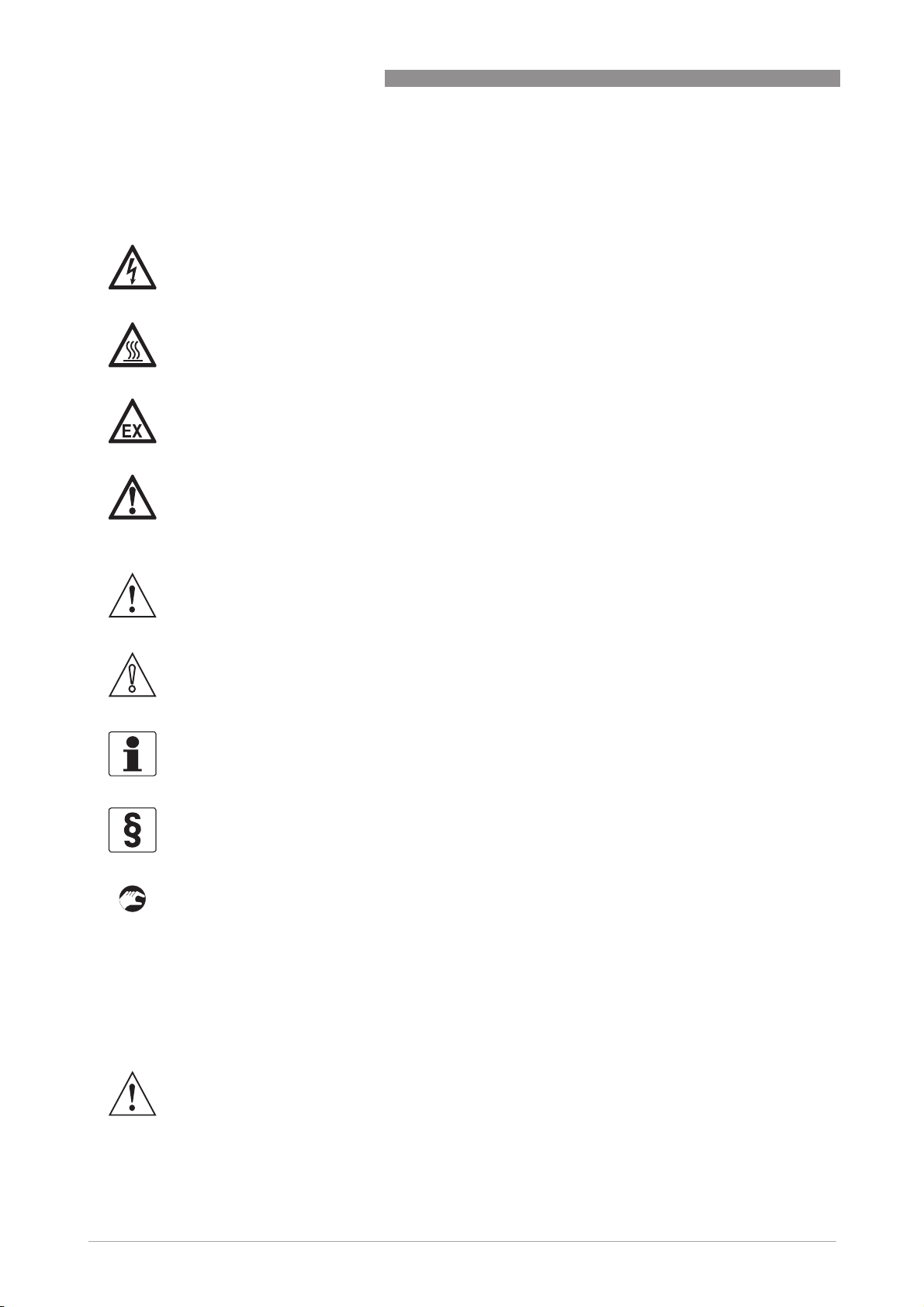
1.4.5 Warnings and symbols used
Safety warnings are indicated by the following symbols.
DANGER!
This warning refers to the immediate danger when working with electricity.
DANGER!
This warning refers to the immediate danger of burns caused by heat or hot surfaces.
DANGER!
This warning refers to the immediate danger when using this device in a hazardous atmosphere.
DANGER!
These warnings must be observed without fail. Even partial disregard of this warning can lead to
serious health problems and even death. There is also the risk of seriously damaging the device
or parts of the operator's plant.
OPTIGAS 4010C
WARNING!
Disregarding this safety warning, even if only in part, poses the risk of serious health problems.
There is also the risk of damaging the device or parts of the operator's plant.
CAUTION!
Disregarding these instructions can result in damage to the device or to parts of the operator's
plant.
INFORMATION!
These instructions contain important information for the handling of the device.
LEGAL NOTICE!
This note contains information on statutory directives and standards.
• HANDLING
HANDLING
HANDLINGHANDLING
This symbol designates all instructions for actions to be carried out by the operator in the
specified sequence.
i RESULT
RESULT
RESULTRESULT
This symbol refers to all important consequences of the previous actions.
1.5 Safety instructions for the operator
WARNING!
In general, devices from the manufacturer may only be installed, commissioned, operated and
maintained by properly trained and authorized personnel.
This document is provided to help you establish operating conditions, which will permit safe and
efficient use of this device.
6
www.krohne.com 07/2014 - 4002962702 - MA OPTIGAS R02 en
Page 7
OPTIGAS 4010C
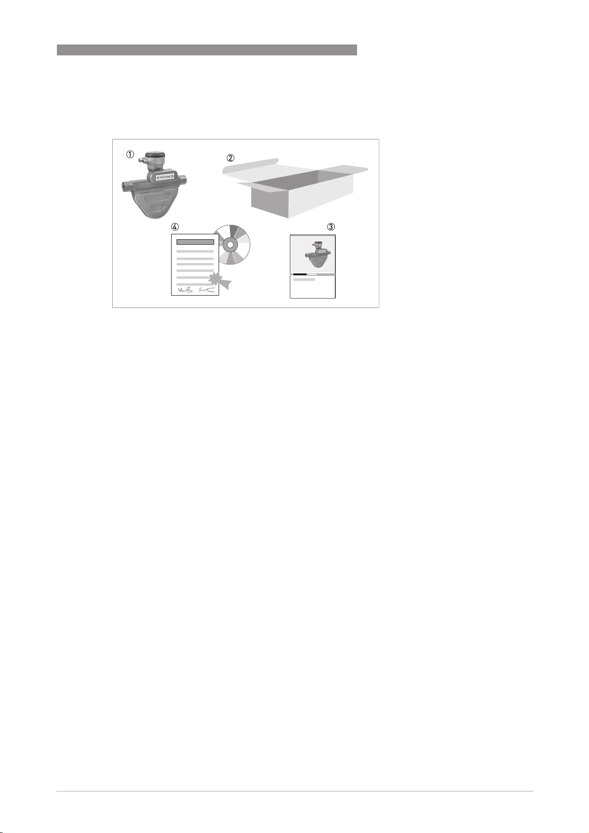
2.1 Scope of delivery
1 Mass flowmeter.
2 Carton.
3 Documentation.
4 CD-ROM and calibration certificate.
DEVICE DESCRIPTION 2
If any items are missing, please contact the manufacturer.
2.2 Device description
This device has been designed for the mass measurement of Compressed Natural Gas (CNG) in
CNG dispensers.
With excellent repeatability and low flow stability, the device is supplied ready to install and
operate. The operating data is factory set according to the order specification but can be changed
with the use of Toolbox.
www.krohne.com07/2014 - 4002962702 - MA OPTIGAS R02 en
7
Page 8

3 INSTALLATION
3.1 Storage
• Store the device in a dry and dust-free location.
• Avoid direct exposure to the sun.
• Store the device in its original packing.
• Do not allow the ambient temperature to fall below -50°C / -58°F or rise above +85°C /
+185°F.
OPTIGAS 4010C
8
www.krohne.com 07/2014 - 4002962702 - MA OPTIGAS R02 en
Page 9

OPTIGAS 4010C
3.2 General notes on installation
INFORMATION!
Inspect the packaging carefully for damages or signs of rough handling. Report damage to the
carrier and to the local office of the manufacturer.
INFORMATION!
Do a check of the packing list to make sure that you have all the elements given in the order.
INFORMATION!
Look at the device nameplate to ensure that the device is delivered according to your order.
Check for the correct supply voltage printed on the nameplate.
3.3 Mounting restrictions
3.3.1 General installation principles
INSTALLATION 3
There are no special installation requirements but you should note the following
points:
• Support the weight of the meter as close to the meter body as possible.
• Mount the meter in such a way to avoid the build up of liquid in the measuring tube.
• Straight runs either side of the meter are not required.
• The use of reducers and other fittings at flanges, including flexible hoses, is allowed but you
should take care to avoid cavitation.
• Avoid extreme pipe size reductions.
• Meters are not affected by crosstalk and can be mounted in series or in parallel.
• Avoid mounting the meter at the lowest point in the pipeline where liquid can collect.
www.krohne.com07/2014 - 4002962702 - MA OPTIGAS R02 en
9
Page 10

3 INSTALLATION
Mounting positions
OPTIGAS 4010C
10
1 Avoid mounting the meter with the flow running uphill because it can cause liquid to build up on the supply side of the
meter.
2 Mount the meter with the flow running downhill. This will allow any build up of liquid to drain from the meter.
3 Avoid mounting the meter with the connection box above the meter. This can cause liquid to collect in the measuring
tubes at their lowest point in the meter.
4 Mount the meter with the junction box underneath the meter. This will prevent liquid from collecting in the measuring
tubes.
5 The meter can be mounted vertically but DO NOT mount it so that the flow is uphill. This can cause fluid to build up on
the supply side of the meter.
6 If you are mounting the meter vertically, mount it so that the flow is downhill. This will allow any build up of fluid to
drain from the meter.
www.krohne.com 07/2014 - 4002962702 - MA OPTIGAS R02 en
Page 11

OPTIGAS 4010C
3.3.2 Flow direction
With the orientation of the meter as shown in the illustration, the factory set flow direction is left
to right.
If the meter has been intalled with the process flow running from right to left, the flow direction
can be changed through the supplied software Toolbox
INSTALLATION 3
Toolbox. Please see the START-UP
ToolboxToolbox
START-UP section.
START-UPSTART-UP
www.krohne.com07/2014 - 4002962702 - MA OPTIGAS R02 en
11
Page 12

4 ELECTRICAL CONNECTIONS
4.1 Safety instructions
DANGER!
All work on the electrical connections may only be carried out with the power disconnected. Take
note of the voltage data on the nameplate!
DANGER!
Observe the national regulations for electrical installations!
DANGER!
For devices used in hazardous areas, additional safety notes apply; please refer to the Ex
documentation.
WARNING!
Observe without fail the local occupational health and safety regulations. Any work done on the
electrical components of the measuring device may only be carried out by properly trained
specialists.
OPTIGAS 4010C
INFORMATION!
Look at the device nameplate to ensure that the device is delivered according to your order.
Check for the correct supply voltage printed on the nameplate.
4.2 Electrical and I/O connections
For information regarding electrical and I/O connections, please refer to the handbook for the
relevant signal converter.
12
www.krohne.com 07/2014 - 4002962702 - MA OPTIGAS R02 en
Page 13

OPTIGAS 4010C
5.1 Spare parts availability
The manufacturer adheres to the basic principle that functionally adequate spare parts for each
device or each important accessory part will be kept available for a period of 3 years after
delivery of the last production run for the device.
This regulation only applies to spare parts which are subject to wear and tear under normal
operating conditions.
5.2 Availability of services
The manufacturer offers a range of services to support the customer after expiration of the
warranty. These include repair, maintenance, technical support and training.
INFORMATION!
For more precise information, please contact your local sales office.
5.3 Fault finding
SERVICE 5
The status of the meter and possible problems, can be checked using the diagnostic functions
available in the Toolbox software supplied with the meter, or Modbus RS485 communication.
There are no serviceable components in the meter. If the Toolbox diagnostics show a fault, the
meter should be replaced.
The following diagnostic functions are available (please refer to the relevant converter Handbook
for register values):
Temperature:
Temperature:
Temperature:Temperature:
This displays the temperature in either °C or °F. The temperature shown should be stable and
the same as the actual process temperature.
Frequency:
Frequency:
Frequency:Frequency:
This displays the vibration frequency of the measuring tubes and should be stable to the first
decimal point. For example, the display might show 230.1xxx Hz. Variations in the first digit after
the decimal point indicates a fluctuation in gas density. This fluctuation can be caused by
changes in pressure / temperature or moisture in the gas.
Drive energy:
Drive energy:
Drive energy:Drive energy:
The typical value of the drive energy for gas with no moisture content is: 1...5%.
Sensor A and B:
Sensor A and B:
Sensor A and B:Sensor A and B:
The display should show values for sensors A and B of 80% and should be within 2% of each
other.
www.krohne.com07/2014 - 4002962702 - MA OPTIGAS R02 en
13
Page 14

5 SERVICE
5.4 Returning the device to the manufacturer
5.4.1 General information
This device has been carefully manufactured and tested. If installed and operated in accordance
with these operating instructions, it will rarely present any problems.
CAUTION!
Should you nevertheless need to return a device for inspection or repair, please pay strict
attention to the following points:
•
Due to statutory regulations on environmental protection and safeguarding the health and
safety of our personnel, manufacturer may only handle, test and repair returned devices that
have been in contact with products without risk to personnel and environment.
•
This means that the manufacturer can only service this device if it is accompanied by the
following certificate (see next section) confirming that the device is safe to handle.
CAUTION!
If the device has been operated with toxic, caustic, flammable or water-endangering products,
you are kindly requested:
•
to check and ensure, if necessary by rinsing or neutralising, that all cavities are free from
such dangerous substances,
•
to enclose a certificate with the device confirming that is safe to handle and stating the
product used.
OPTIGAS 4010C
14
www.krohne.com 07/2014 - 4002962702 - MA OPTIGAS R02 en
Page 15

OPTIGAS 4010C
5.4.2 Form (for copying) to accompany a returned device
Company: Address:
Department: Name:
Tel. no.: Fax no.:
Manufacturer's order no. or serial no.:
The device has been operated with the following medium:
SERVICE 5
This medium is: radioactive
water-hazardous
toxic
caustic
flammable
We checked that all cavities in the device are free from such
substances.
We have flushed out and neutralized all cavities in the
device.
We hereby confirm that there is no risk to persons or the environment through any residual media
contained in the device when it is returned.
Date: Signature:
Stamp:
5.5 Disposal
CAUTION!
Disposal must be carried out in accordance with legislation applicable in your country.
www.krohne.com07/2014 - 4002962702 - MA OPTIGAS R02 en
15
Page 16

6 TECHNICAL DATA
6.1 Measuring principle
Meter from the side, showing tube layout
1
OPTIGAS 4010C
3
2
1 Measuring tubes
2 Drive coil
3 Sensor 1
4 Sensor 2
Static meter not energised and with no flow
4
16
1 Measuring tubes
2 Drive coil
3 Sensor 1
4 Sensor 2
A Coriolis twin-tube mass flowmeter consists of two measuring tubes (1) a drive coil (2) and
two sensors (3 and 4) that are positioned either side of the drive coil.
www.krohne.com 07/2014 - 4002962702 - MA OPTIGAS R02 en
Page 17

OPTIGAS 4010C
Energised meter
1 Measuring tubes
2 Direction of oscilation
3 Sine wave
When the meter is energised, the drive coil vibrates the measuring tubes causing them to
oscillate and produce a sine wave (3). The sine wave is monitored by the two sensors.
Energised meter with process flow
TECHNICAL DATA 6
1 Process flow
2 Sine wave
3 Phase shift
When a fluid or gas passes through the tubes, the Coriolis effect causes a phase shift in the sine
wave that is detected by the two sensors. This phase shift is directly proportional to the mass
flow.
Temperature measurement is made using a Pt500 sensor.
www.krohne.com07/2014 - 4002962702 - MA OPTIGAS R02 en
17
Page 18

6 TECHNICAL DATA
OPTIGAS 4010C
6.2 Technical data
INFORMATION!
•
The following data is provided for general applications. If you require data that is more
relevant to your specific application, please contact us or your local sales office.
•
Additional information (certificates, special tools, software,...) and complete product
documentation can be downloaded free of charge from the website (Download Center).
Measuring system
Measuring principle Coriolis mass flow
Application range Measurement of Compressed Natural Gas (CNG)
Measured values Mass, standard or normal volume, temperature (volume & density for liquids
Design
Basic System consists of a measuring sensor with integral MFC010 converter to
Features Fully welded maintenance- free sensor with twin U-shaped measuring tube
only)
process the output signal.
Application conditions
Fluid Compressed Natural Gas (CNG) with operating pressure typically > 100 barg
Flow range capacity 1...70 kg/min / 2.2...155 lbs/min
Accuracy ±0.5% of total batch (where minimum actual flow rate is 1 kg/min / 2.2
Repeatability ±0.3% of actual flow rate + zero stability (for a batch size > 1 kg . 2.2lbs)
Zero stability ±0.015% of flow range capacity
Pressure rating
Pressure rating
Pressure ratingPressure rating
Static 350 barg / 5076 psig
Cycling 300 barg / 4351 psig
Process fluid temperature -40...+93°C / -40…+200°F
Ambient temperature -40...+55°C / -40…+131°F
/ 1450 psig
lbs/min)
Mechanical
Process connections ¾" NPT female (adaptor options are available)
Materials
Materials
MaterialsMaterials
Measuring tube Stainless Steel 316L (1.4404)
Outer casing
Sensor electronics housing
Junction box Die cast Aluminium (polyurethane coating)
Electrical
Power supply 12 VDC via Ex approved barrier (11.4...12.6 VDC)
Programming Via Modbus. 1
Outputs Modbus RTU over RS485
Diagnostics
18
www.krohne.com 07/2014 - 4002962702 - MA OPTIGAS R02 en
Page 19

OPTIGAS 4010C
TECHNICAL DATA 6
Interface cable 2 x screened twisted pairs with a minimum 20 AWG conductors. Total C ≤
Cable glands M20 X 1.5 Stainless Steel suitable for cable diameter 6.5...9.5 mm
50nF, total L ≤ 200µH
Approvals
Custody transfer PTB type approval 5.411 / 04.15
Vibration IEC 60068-2-6
ATEX (acc. 94/9/EC)
ATEX (acc. 94/9/EC)
ATEX (acc. 94/9/EC)ATEX (acc. 94/9/EC)
OPTIGAS 4010C without heating jacket / insulation
OPTIGAS 4010C without heating jacket / insulation
OPTIGAS 4010C without heating jacket / insulationOPTIGAS 4010C without heating jacket / insulation
II 1/2 G Ex ib IIC T4...T1 Ga/Gb
II 2 D Ex ib IIIC T210°C Db
Ex ib IIC T4...T1 Ga/Gb
Ex ib IIIC T210°C Db
IECEx
IECEx
IECExIECEx
Ex ib IIC T6...T1 Ga/Gb
Ex ib IIIC T4*** °C Db
NEPSI
NEPSI
NEPSINEPSI
OPTIGAS 4010C
OPTIGAS 4010C
OPTIGAS 4010COPTIGAS 4010C
Ex ib IIC T4...T1 Ga/Gb
1 Toolbox software is available from the manufacturer but it requires a compatible Modbus to PC adapter with approved barrier. Please
call for more information.
ATEX (acc. 94/9/EC) temperature limits
Ambient temp.
Tamb °C
OPTIGAS 4010C without heating jacket /
insulation
-40...+65 60 T4 T130
Max. medium
temp. Tm °C
125 T3 T195
140 T2 - T21 T210
Temp. class Max. surface
temp. °C
www.krohne.com07/2014 - 4002962702 - MA OPTIGAS R02 en
19
Page 20

6 TECHNICAL DATA
6.3 Dimensions and weights
OPTIGAS 4010C
[mm] [inches]
A 359 ±2 14.1 ±0.08
B 97 3.8
C 162 6.4
D 194 7.6
E 50 1.97
20
www.krohne.com 07/2014 - 4002962702 - MA OPTIGAS R02 en
Page 21

OPTIGAS 4010C
NOTES 7
www.krohne.com07/2014 - 4002962702 - MA OPTIGAS R02 en
21
Page 22

7 NOTES
OPTIGAS 4010C
22
www.krohne.com 07/2014 - 4002962702 - MA OPTIGAS R02 en
Page 23

OPTIGAS 4010C
NOTES 7
www.krohne.com07/2014 - 4002962702 - MA OPTIGAS R02 en
23
Page 24

KROHNE product overview
• Electromagnetic flowmeters
• Variable area flowmeters
• Ultrasonic flowmeters
• Mass flowmeters
• Vortex flowmeters
• Flow controllers
• Level meters
• Temperature assemblies
• Pressure transmitters
• Analysis products
• Products and systems for the oil & gas industry
• Measuring systems for the marine industry
Head Office KROHNE Messtechnik GmbH
Ludwig-Krohne-Str. 5
47058 Duisburg (Germany)
Tel.:+49 203 301 0
Fax:+49 203 301 103 89
info@krohne.com
The current list of all KROHNE contacts and addresses can be found at:
© KROHNE 07/2014 - 4002962702 - MA OPTIGAS R02 en - Subject to change without notice.
www.krohne.com
 Loading...