

Page 1
Quick Start
Quick Start
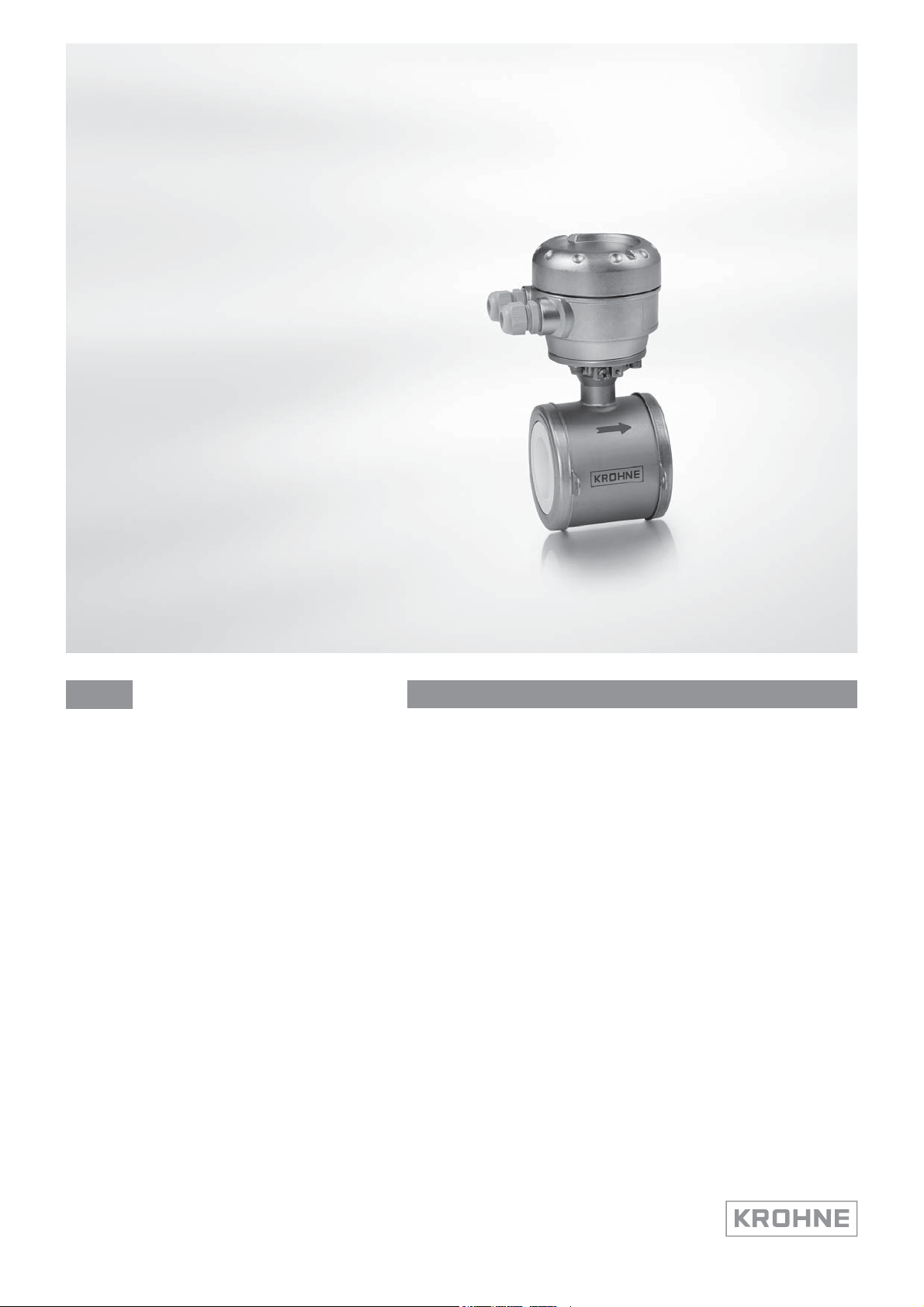
OPTIFLUX 5000
OPTIFLUX 5000
OPTIFLUX 5000OPTIFLUX 5000
Quick StartQuick Start
Electromagnetic flowmeter in sandwich version
The documentation is only complete when used in combination with the relevant
documentation for the signal converter.
© KROHNE 04/2017 - 4004943902 - QS OPTIFLUX 5000 SW R05 en
Page 2

CONTENTS
OPTIFLUX 5000
1 Safety instructions 3
2 Installation 4
2.1 Scope of delivery............................................................................................................... 4
2.2 Device description ............................................................................................................ 5
2.3 Nameplates (examples) ................................................................................................... 6
2.4 Storage ............................................................................................................................. 7
2.5 Transport .......................................................................................................................... 7
2.6 Pre-installation requirements ......................................................................................... 7
2.7 General requirements...................................................................................................... 8
2.7.1 Vibration ..................................................................................................................................8
2.7.2 Magnetic field.......................................................................................................................... 8
2.8 Installation conditions ...................................................................................................... 9
2.8.1 Inlet and outlet........................................................................................................................ 9
2.8.2 Bends in 2 or 3 dimensions..................................................................................................... 9
2.8.3 T-section ............................................................................................................................... 10
2.8.4 Bends .................................................................................................................................... 10
2.8.5 Open feed or discharge......................................................................................................... 11
2.8.6 Flange deviation.................................................................................................................... 11
2.8.7 Pump ..................................................................................................................................... 11
2.8.8 Control valve ......................................................................................................................... 12
2.8.9 Air venting and vacuum forces ............................................................................................. 12
2.8.10 Mounting position................................................................................................................ 13
2.9 Mounting......................................................................................................................... 13
2.9.1 Torques and pressure........................................................................................................... 13
3 Electrical connections 16
3.1 Safety instructions.......................................................................................................... 16
3.2 Grounding ....................................................................................................................... 16
3.3 Virtual reference for IFC 300 (W and F version)............................................................ 17
3.4 Connection diagrams ..................................................................................................... 17
4 Technical data 18
4.1 Dimensions and weights ................................................................................................ 18
5 Notes 22
2
www.krohne.com 04/2017 - 4004943902 - QS OPTIFLUX 5000 SW R05 en
Page 3
OPTIFLUX 5000
Warnings and symbols used
DANGER!
This information refers to the immediate danger when working with electricity.
DANGER!
These warnings must be observed without fail. Even partial disregard of this warning can lead to
serious health problems and even death. There is also the risk of seriously damaging the device
or parts of the operator's plant.
WARNING!
Disregarding this safety warning, even if only in part, poses the risk of serious health problems.
There is also the risk of damaging the device or parts of the operator's plant.
CAUTION!
Disregarding these instructions can result in damage to the device or to parts of the operator's
plant.
INFORMATION!
These instructions contain important information for the handling of the device.
SAFETY INSTRUCTIONS
1
HANDLING
• This symbol designates all instructions for actions to be carried out by the operator in the
specified sequence.
i
RESULT
RESULT
RESULTRESULT
This symbol refers to all important consequences of the previous actions.
Safety instructions for the operator
CAUTION!
Installation, assembly, start-up and maintenance may only be performed by appropriately
trained personnel. The regional occupational health and safety directives must always be
observed.
LEGAL NOTICE!
The responsibility as to the suitability and intended use of this device rests solely with the user.
The supplier assumes no responsibility in the event of improper use by the customer. Improper
installation and operation may lead to loss of warranty. In addition, the "Terms and Conditions of
Sale" apply which form the basis of the purchase contract.
INFORMATION!
•
Further information can be found on the supplied CD-ROM in the manual, on the data sheet,
in special manuals, certificates and on the manufacturer's website.
•
If you need to return the device to the manufacturer or supplier, please fill out the form
contained on the CD-ROM and send it with the device. Unfortunately, the manufacturer
cannot repair or inspect the device without the completed form.
www.krohne.com04/2017 - 4004943902 - QS OPTIFLUX 5000 SW R05 en
3
Page 4
2
INSTALLATION
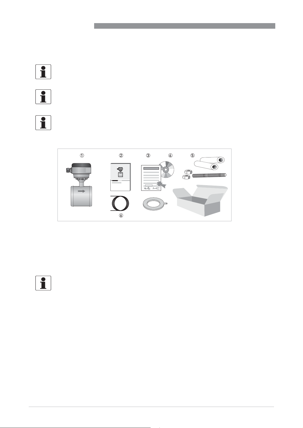
2.1 Scope of delivery
INFORMATION!
Do a check of the packing list to make sure that you have all the elements given in the order.
INFORMATION!
Inspect the packaging carefully for damages or signs of rough handling. Report damage to the
carrier and to the local office of the manufacturer.
INFORMATION!
The remote version will arrive in two cartons. One carton contains the converter and one carton
contains the sensor.
OPTIFLUX 5000
7
Figure 2-1: Scope of delivery
1 Ordered flowmeter
2 Product documentation
3 Factory calibration report
4 CD-ROM with product documentation in available languages
5 Mounting material (rubber sleeves). Optional; studs and bolts.
6 Signal cable (remote versions only)
7 Grounding rings (optional)
INFORMATION!
Assembly materials and tools are not part of the delivery. Use the assembly materials and tools
in compliance with the applicable occupational health and safety directives.
4
www.krohne.com 04/2017 - 4004943902 - QS OPTIFLUX 5000 SW R05 en
Page 5
OPTIFLUX 5000
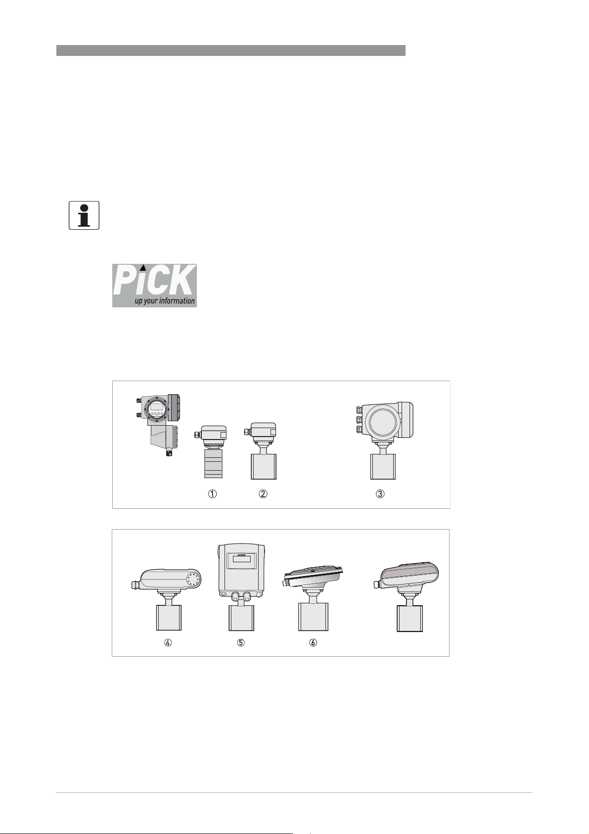
2.2 Device description
Electromagnetic flowmeters are designed exclusively to measure the flow and conductivity of
electrically conductive, liquid media.
Your measuring device is supplied ready for operation. The factory settings for the operating
data have been made in accordance with your order specifications.
INFORMATION!
Product specific information and extensive product specification is available using PICK, the
Product Information Center KROHNE web-tool.
PICK can be found via the service menu button on the KROHNE.com website.
The following versions are available:
• Compact version (the signal converter is mounted directly on the measuring sensor)
• Remote version (a measuring sensor with connection box and a separate signal converter)
INSTALLATION
2
1 Remote version (DN2.5...15)
2 Remote version (DN25...100)
3 Compact version with IFC 300 signal converter
4 Compact version with IFC 100 (0°) signal converter
5 Compact version with IFC 100 (45°) signal converter
6 Compact version with IFC 100 SS (10°) signal converter
7 Compact version with IFC 050 (10°) signal converter
www.krohne.com04/2017 - 4004943902 - QS OPTIFLUX 5000 SW R05 en
7
5
Page 6

2
INSTALLATION
2.3 Nameplates (examples)
INFORMATION!
Look at the device nameplate to ensure that the device is delivered according to your order.
Check for the correct supply voltage printed on the nameplate.
1 Name and address of the manufacturer
2 Type designation of the flowmeter,and CE sign with number(s) of notified body / bodies
3 Calibration data
4 PED data
OPTIFLUX 5000
6
www.krohne.com 04/2017 - 4004943902 - QS OPTIFLUX 5000 SW R05 en
Page 7
OPTIFLUX 5000
2.4 Storage
• Store the device in a dry and dust-free location.
• Avoid lasting direct exposure to the sun.
• Store the device in its original packaging.
• Storage temperature: -50...+70°C / -58...+158°F
2.5 Transport
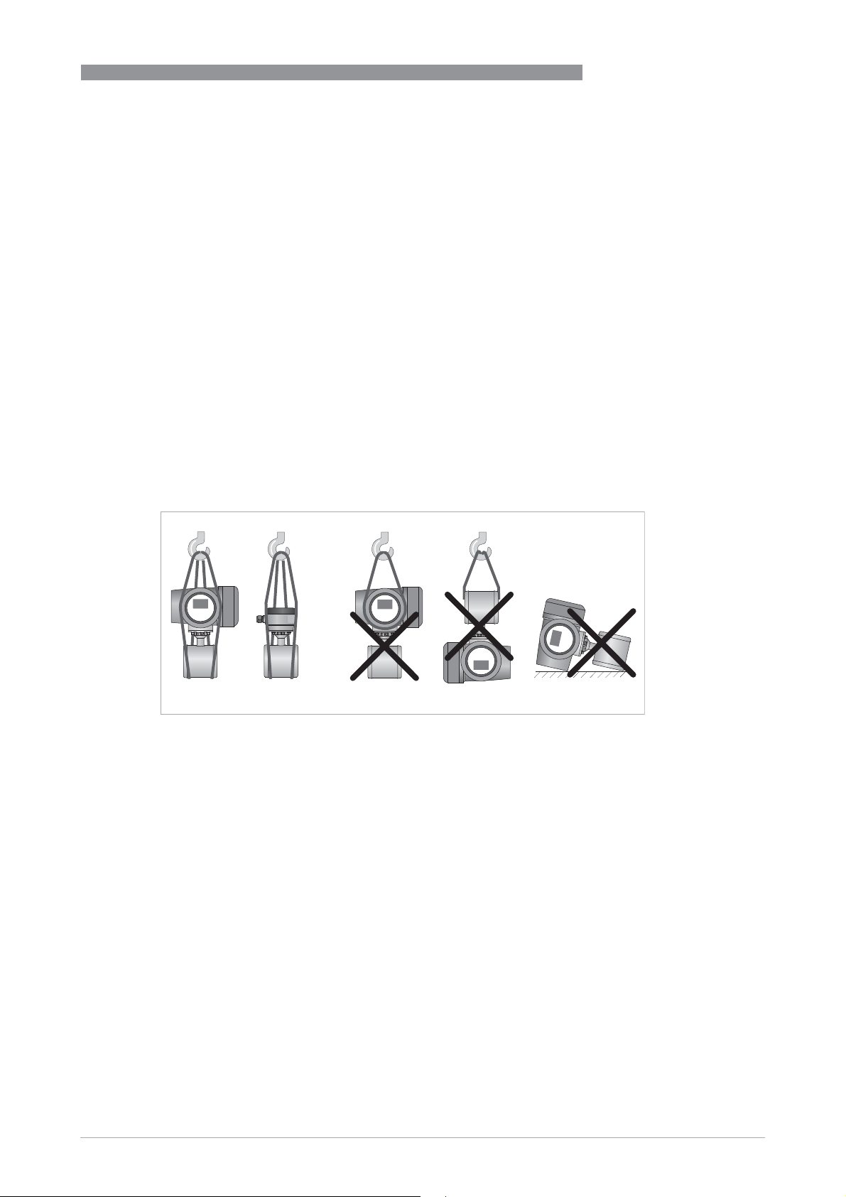
Signal converter
• No special requirements.
Compact version
• Do not lift the device by the signal converter housing.
• Do not use lifting chains.
• To transport the device, use lifting straps.
INSTALLATION
2
Figure 2-2: Transport
2.6 Pre-installation requirements
Make sure that you have all necessary tools available:
• Allen key (4 mm)
• Small screwdriver
• Wrench for cable glands
• Wrench for wall mounting bracket (remote version only)
• Torque wrench for installing flowmeter in pipeline
www.krohne.com04/2017 - 4004943902 - QS OPTIFLUX 5000 SW R05 en
7
Page 8
2
INSTALLATION
2.7 General requirements
INFORMATION!
The following precautions must be taken to ensure reliable installation.
•
Make sure that there is adequate space to the sides.
•
Protect the signal converter from direct sunlight and install a sun shade if necessary.
•
Signal converters installed in control cabinets require adequate cooling, e.g. by fan or heat
exchanger.
•
Do not expose the signal converter to intense vibration. The flowmeters are tested for a
vibration level in accordance with IEC 68-2-64.
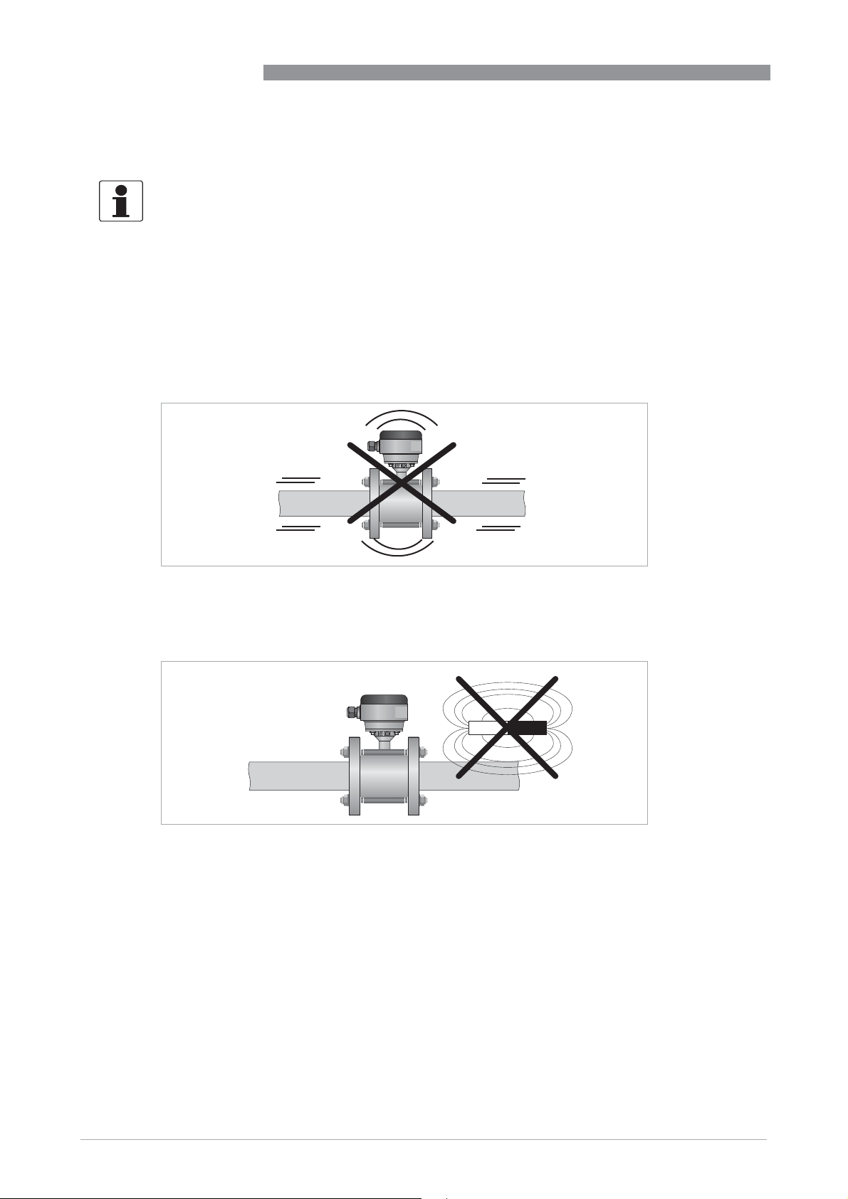
2.7.1 Vibration
OPTIFLUX 5000
Figure 2-3: Avoid vibrations
2.7.2 Magnetic field
Figure 2-4: Avoid magnetic fields
8
www.krohne.com 04/2017 - 4004943902 - QS OPTIFLUX 5000 SW R05 en
Page 9

OPTIFLUX 5000
2.8 Installation conditions
2.8.1 Inlet and outlet
Use straight inlet and outlet pipe sections to prevent flow distortion or swirl, caused by bends
and T-sections.
Figure 2-5: Recommended inlet and outlet section
1 Refer to chapter "Bends in 2 or 3 dimensions"
2 t 2 DN
INSTALLATION
2
2.8.2 Bends in 2 or 3 dimensions
Figure 2-6: Inlet when using 2 and/or 3 dimensional bends upstream of the flowmeter
Inlet length: using bends in 2 dimensions: t 5 DN; when having bends in 3 dimensions: t 10 DN
INFORMATION!
2 Dimensional bends occur in a vertical plane only, while 3 Dimensional bends occur in both
vertical and
and horizontal plane.
andand
www.krohne.com04/2017 - 4004943902 - QS OPTIFLUX 5000 SW R05 en
9
Page 10

2
INSTALLATION
2.8.3 T-section
Figure 2-7: Distance behind a T-section
1 t 10 DN
2.8.4 Bends
OPTIFLUX 5000
10
CAUTION!
Avoid draining or partial filling of the flow sensor
www.krohne.com 04/2017 - 4004943902 - QS OPTIFLUX 5000 SW R05 en
Page 11

OPTIFLUX 5000
2.8.5 Open feed or discharge
Figure 2-8: Installation in front of an open discharge
2.8.6 Flange deviation
CAUTION!
Max. permissible deviation of pipe flange faces:
- L
L
max
d 0.5 mm / 0.02"
min
INSTALLATION
2
2.8.7 Pump
Figure 2-9: Flange deviation
1 L
max
2 L
min
Figure 2-10: Installation behind a pump
www.krohne.com04/2017 - 4004943902 - QS OPTIFLUX 5000 SW R05 en
11
Page 12

2
INSTALLATION
2.8.8 Control valve
Figure 2-11: Installation in front of a control valve
2.8.9 Air venting and vacuum forces
OPTIFLUX 5000
Figure 2-12: Air venting
1 t 5 m / 17 ft
2 Air ventilation point
Figure 2-13: Vacuum
1 t 5 m / 17 ft
12
www.krohne.com 04/2017 - 4004943902 - QS OPTIFLUX 5000 SW R05 en
Page 13

OPTIFLUX 5000
2.8.10 Mounting position
Figure 2-14: Mounting position
2.9 Mounting
CAUTION!
Please take care to use the proper gasket to prevent damaging the liner of the flowmeter. In
general, the use of spiral wound gaskets is not advised, as it could severely damage the liner of
the flowmeter.
INSTALLATION
2
2.9.1 Torques and pressure
WARNING!
•
Please use stainless steel A2 / 6.9 class bolts.
•
Make sure the connecting flanges are of type raised face (RF).
Figure 2-15: Tighten the bolts in fixed order, see picture.
Max. torque:
• Step 1: approx. 50% of max. torque
• Step 2: approx. 80% of max. torque
• Step 3: 100% of max. torque given in tables
www.krohne.com04/2017 - 4004943902 - QS OPTIFLUX 5000 SW R05 en
13
Page 14

2
INSTALLATION
EN 1092-1
OPTIFLUX 5000
Nominal size
DN [mm]
2.5...80 PN 40 40
100 PN 16 16
100 PN 25 25
Pressure rating Max. allowable operating pressure
[bar]
ASME B 16.5
Nominal size
[inch]
1/10...4" 150 lb 230
1/10...3" 300 lb 580
Pressure rating Max. allowable operating pressure
[psig]
CAUTION!
•
Pressures at 20°C / 68°F.
•
For higher temperatures, the pressure and temperature ratings are as per ASME B16.5.
14
www.krohne.com 04/2017 - 4004943902 - QS OPTIFLUX 5000 SW R05 en
Page 15

OPTIFLUX 5000
INFORMATION!
The specified torque values are dependent on variables (temperature, bolt material, gasket
material, lubricants, etc.) which are not within the control of the manufacturer. Therefore the
values should be regarded as indicative only.
EN 1092-1
INSTALLATION
2
Nominal
Counter flanges & bolts Max. allowable torque
size
DN [mm]
Gasket:
Filled PTFE / PTFE
Gasket:
Graphite
O-ring
/ PF29
Rating Size Nm ft-lb Nm ft-lb Nm ft-lb
2.5...10 PN 40 M12 x 141 - - - - 32 24
15 PN 40 M12 x 141 - - - - 36 27
25 PN 40 M12 x 141 22 16 32 24 - -
40 PN 40 M16 x 176 47 35 66 49 - -
50 PN 40 M16 x 203 58 43 82 60 - -
80 PN 40 M16 x 261 48 35 69 51 - -
100 PN 16 M16 x 303 75 55 106 78 - -
100 PN 25 M20 x 176 94 69 133 98 - -
ASME B 16.5
Nominal
size
[inch]
Counter flanges & bolts Max. allowable torque
Gaskets:
Filled PTFE/ PTFE
Gaskets:
Graphite
/ PF29
O-ring
Rating Size Nm ft-lb Nm ft-lb Nm ft-lb
1/10...3/8
1/2" 150 lb 1/2"UNC x 142 - - - - 35 26
1" 150 lb 1/2"UNC x 142 24 18 33 24 - -
1 1/2" 150 lb 1/2"UNC x 174 38 28 54 40 - -
2" 150 lb 5/8"UNC x 215 58 43 83 61 - -
3" 150 lb 5/8"UNC x 268 98 72 138 102 - -
4" 150 lb 5/8"UNC x 318 75 55 108 80 - -
150 lb 1/2"UNC x 142 - - - - 35 26
"
www.krohne.com04/2017 - 4004943902 - QS OPTIFLUX 5000 SW R05 en
15
Page 16

3
ELECTRICAL CONNECTIONS
3.1 Safety instructions
DANGER!
All work on the electrical connections may only be carried out with the power disconnected. Take
note of the voltage data on the nameplate!
DANGER!
Observe the national regulations for electrical installations!
DANGER!
For devices used in hazardous areas, additional safety notes apply; please refer to the Ex
documentation.
WARNING!
Observe without fail the local occupational health and safety regulations. Any work done on the
electrical components of the measuring device may only be carried out by properly trained
specialists.
OPTIFLUX 5000
INFORMATION!
Look at the device nameplate to ensure that the device is delivered according to your order.
Check for the correct supply voltage printed on the nameplate.
3.2 Grounding
DANGER!
The device must be grounded in accordance with regulations in order to protect personnel
against electric shocks.
Figure 3-1: Grounding
1 Metal pipelines, not internally coated. Grounding without grounding rings!
2 Metal pipelines with internal coating and non-conductive pipelines. Grounding with grounding rings!
16
www.krohne.com 04/2017 - 4004943902 - QS OPTIFLUX 5000 SW R05 en
Page 17

OPTIFLUX 5000
Figure 3-2: Grounding ring number 1
Grounding ring number 1 (optional for DN25...150 / 1...6"):
Grounding ring number 1 (optional for DN25...150 / 1...6"): Thickness: 3 mm / 0.1" (tantalum: 0.5
Grounding ring number 1 (optional for DN25...150 / 1...6"):Grounding ring number 1 (optional for DN25...150 / 1...6"):
mm / 0.02")
ELECTRICAL CONNECTIONS
INFORMATION!
For diameter DN10 / 3/8" and DN15 / 1/2", grounding rings are integrated as standard in the flow
sensor construction.
3.3 Virtual reference for IFC 300 (W and F version)
3
Figure 3-3: Virtual reference
Minimum requirements:
• Size: t DN10 / 3/8"
• Electrical conductivity: t 200 μS/cm
• Signal cable: max. 50 m / 164 ft, type DS
3.4 Connection diagrams
INFORMATION!
For the connection diagrams, please refer to the documentation of the applicable converter.
www.krohne.com04/2017 - 4004943902 - QS OPTIFLUX 5000 SW R05 en
17
Page 18

4
TECHNICAL DATA
4.1 Dimensions and weights
Remote version:
Remote version:
Remote version:Remote version:
DN2.5...15 / 1/10...1/2"
Remote version:
Remote version:
Remote version:Remote version:
DN25...100 / 1...4"
OPTIFLUX 5000
a = 88 mm / 3.5"
b = 139 mm / 5.5"
c = 106 mm / 4.2"
Total height = H + a
a = 88 mm / 3.5"
b = 139 mm / 5.5"
c = 106 mm / 4.2"
Total height = H + a
1
1
Compact version with
Compact version with
Compact version with Compact version with
IFC 300
IFC 300
IFC 300IFC 300
Compact version with
Compact version with
Compact version with Compact version with
IFC 100 (0
IFC 100 (0°)
IFC 100 (0IFC 100 (0
)
))
a = 155 mm / 6.1"
b = 230 mm / 9.1"
c = 260 mm / 10.2"
Total height = H + a
a = 82 mm / 3.2"
b = 161 mm / 6.3"
c = 257 mm / 10.1"
Total height = H + a
1
1
18
www.krohne.com 04/2017 - 4004943902 - QS OPTIFLUX 5000 SW R05 en
Page 19

OPTIFLUX 5000
Compact version with
Compact version with
Compact version with Compact version with
IFC 100 (45
IFC 100 (45°)
IFC 100 (45IFC 100 (45
Compact version with
Compact version with
Compact version with Compact version with
IFC 100 SS (10
IFC 100 SS (10°)
IFC 100 SS (10IFC 100 SS (10
Compact version with
Compact version with
Compact version withCompact version with
IFC 050 (10
IFC 050 (10°)
IFC 050 (10IFC 050 (10
TECHNICAL DATA
)
))
)
))
)
))
a = 186 mm / 7.3"
b = 161 mm / 6.3"
c = 184 mm / 2.7"
Total height = H + a
a = 100 mm / 4"
b = 187 mm / 7.36"
c = 270 mm / 10.63"
Total height = H + a
a = 100mm / 4"
b = 157 mm / 6.18"
c = 260 mm / 10.24"
Total height = H + a
4
1
1
1
1 The value may vary depending on the used cable glands.
www.krohne.com04/2017 - 4004943902 - QS OPTIFLUX 5000 SW R05 en
19
Page 20

4
TECHNICAL DATA
Figure 4-1: Construction details DN2.5...15 / 1/10...1/2"
1 O-ring
2 Grounding ring
OPTIFLUX 5000
20
Figure 4-2: Construction details DN25...100 / 1...4"
1 Situation without grounding rings
2 Gasket
INFORMATION!
•
All data given in the following tables are based on standard versions of the flow sensor only.
•
Especially for smaller nominal sizes of the flow sensor, the signal converter can be bigger
than the flow sensor.
•
Note that for other pressure ratings than mentioned, the dimensions may be different.
•
For full information on signal converter dimensions see relevant documentation.
www.krohne.com 04/2017 - 4004943902 - QS OPTIFLUX 5000 SW R05 en
Page 21

OPTIFLUX 5000
TECHNICAL DATA
4
Nominal
Dimensions [mm] Approx.
size
DN L H W D Ød1 Ød4
2.5 65
4 65
6 65
10 65
15 65
25 58
40 83
50 103
80 153
100 203
1 Total fitting length of flowmeter with integrated rings: dimension L + 2 x gasket thickness.
2 Total fitting length of flowmeter without rings: dimension L only.
Nominal
1
1
1
1
1
2
2
2
2
2
123 44 - - 1.6
123 44 - - 1.6
123 44 - - 1.6
123 44 - - 1.6
123 44 - - 1.6
116 68 20 26 46 1.6
131 83 30 39 62 2.4
149 101 40 51 74 2.9
181 133 60 80 106 6.4
206 158 80 101 133 8.8
Dimensions [inches] Approx.
size
ASME L H W D Ød1 Ød4
weight [kg]
weight [lb]
1/10" 2.56
1/8" 2.56
¼" 2.56
3/8" 2.56
½" 2.56
1" 2.28
1½" 3.27
2" 4.06
3" 6.02
4" 7.99
1 Total fitting length of flowmeter with integrated rings: dimension L + 2 x gasket thickness.
2 Total fitting length of flowmeter without rings: dimension L only.
1
1
1
1
1
2
2
2
2
2
4.84 1.73 - - 3.53
4.84 1.73 - - 3.53
4.84 1.73 - - 3.53
4.84 1.73 - - 3.53
4.84 1.73 - - 3.53
4.57 2.68 0.79 1.02 1.81 3.53
5.16 3.27 1.18 1.54 2.44 5.29
5.87 3.98 1.57 2.01 2.91 6.39
7.13 5.24 2.36 3.15 4.17 14.11
8.11 6.22 3.15 3.98 5.24 19.40
www.krohne.com04/2017 - 4004943902 - QS OPTIFLUX 5000 SW R05 en
21
Page 22

5
NOTES
OPTIFLUX 5000
22
www.krohne.com 04/2017 - 4004943902 - QS OPTIFLUX 5000 SW R05 en
Page 23

OPTIFLUX 5000
NOTES
5
www.krohne.com04/2017 - 4004943902 - QS OPTIFLUX 5000 SW R05 en
23
Page 24

KROHNE – Process instrumentation and measurement solutions
•
Flow
•
Level
•
Temperature
•
Pressure
•
Process Analysis
•
Services
Head Office KROHNE Messtechnik GmbH
Ludwig-Krohne-Str. 5
47058 Duisburg (Germany)
Tel.: +49 203 301 0
Fax: +49 203 301 10389
info@krohne.com
© KROHNE 04/2017 - 4004943902 - QS OPTIFLUX 5000 SW R05 en - Subject to change without notice.
The current list of all KROHNE contacts and addresses can be found at:
www.krohne.com
 Loading...