

Page 1
Quick Start
Quick Start
OPTIFLUX 5000
OPTIFLUX 5000
OPTIFLUX 5000OPTIFLUX 5000
Quick Start Quick Start
Electromagnetic flowmeter in flanged version
The documentation is only complete when used in combination with the relevant
documentation for the signal converter.
© KROHNE 04/2011 - 7309872300 - QS OPTIFLUX 5000 FL R03 en
Page 2

CONTENTS
OPTIFLUX 5000
1 Safety instructions 3
2 Installation 4
2.1 Scope of delivery............................................................................................................... 4
2.2 Device description ............................................................................................................ 5
2.3 Nameplates ...................................................................................................................... 5
2.4 Storage ............................................................................................................................. 6
2.5 Transport .......................................................................................................................... 6
2.6 Installation conditions ...................................................................................................... 7
2.6.1 Inlet and outlet........................................................................................................................ 7
2.6.2 Mounting position.................................................................................................................... 7
2.6.3 Flange deviation...................................................................................................................... 8
2.6.4 T-section ................................................................................................................................. 8
2.6.5 Vibration ..................................................................................................................................8
2.6.6 Magnetic field.......................................................................................................................... 9
2.6.7 Bends ...................................................................................................................................... 9
2.6.8 Open discharge .....................................................................................................................10
2.6.9 Control valve ......................................................................................................................... 10
2.6.10 Air venting ........................................................................................................................... 10
2.6.11 Pump ................................................................................................................................... 11
2.6.12 Temperatures ..................................................................................................................... 11
2.7 Mounting......................................................................................................................... 12
2.7.1 Torques and pressures......................................................................................................... 12
3 Electrical connections 14
3.1 Safety instructions.......................................................................................................... 14
3.2 Grounding ....................................................................................................................... 14
3.3 Virtual reference for IFC 300 (C, W and F version) ........................................................ 15
3.4 Connection diagrams ..................................................................................................... 15
4 Technical data 16
4.1 Measuring principle........................................................................................................16
4.2 Dimensions and weights ................................................................................................ 17
2
www.krohne.com 04/2011 - 7309872300 - QS OPTIFLUX 5000 FL R03 en
Page 3
OPTIFLUX 5000
Warnings and symbols used
DANGER!
This information refers to the immediate danger when working with electricity.
DANGER!
These warnings must be observed without fail. Even partial disregard of this warning can lead to
serious health problems and even death. There is also the risk of seriously damaging the device
or parts of the operator's plant.
WARNING!
Disregarding this safety warning, even if only in part, poses the risk of serious health problems.
There is also the risk of damaging the device or parts of the operator's plant.
CAUTION!
Disregarding these instructions can result in damage to the device or to parts of the operator's
plant.
INFORMATION!
These instructions contain important information for the handling of the device.
SAFETY INSTRUCTIONS 1
HANDLING
• This symbol designates all instructions for actions to be carried out by the operator in the
specified sequence.
i RESULT
RESULT
RESULTRESULT
This symbol refers to all important consequences of the previous actions.
Safety instructions for the operator
CAUTION!
Installation, assembly, start-up and maintenance may only be performed by appropriately
trained personnel. The regional occupational health and safety directives must always be
observed.
LEGAL NOTICE!
The responsibility as to the suitability and intended use of this device rests solely with the user.
The supplier assumes no responsibility in the event of improper use by the customer. Improper
installation and operation may lead to loss of warranty. In addition, the "Terms and Conditions of
Sale" apply which form the basis of the purchase contract.
INFORMATION!
•
Further information can be found on the supplied CD-ROM in the manual, on the data sheet,
in special manuals, certificates and on the manufacturer's website.
•
If you need to return the device to the manufacturer or supplier, please fill out the form
contained on the CD-ROM and send it with the device. Unfortunately, the manufacturer
cannot repair or inspect the device without the completed form.
www.krohne.com04/2011 - 7309872300 - QS OPTIFLUX 5000 FL R03 en
3
Page 4
2 INSTALLATION
2.1 Scope of delivery
INFORMATION!
Check the packing list to check if you received completely all that you ordered.
INFORMATION!
Inspect the cartons carefully for damage or signs of rough handling. Report damage to the
carrier and to the local office of the manufacturer.
INFORMATION!
The device will arrive in two cartons. One carton contains the converter and one carton contains
the sensor.
OPTIFLUX 5000
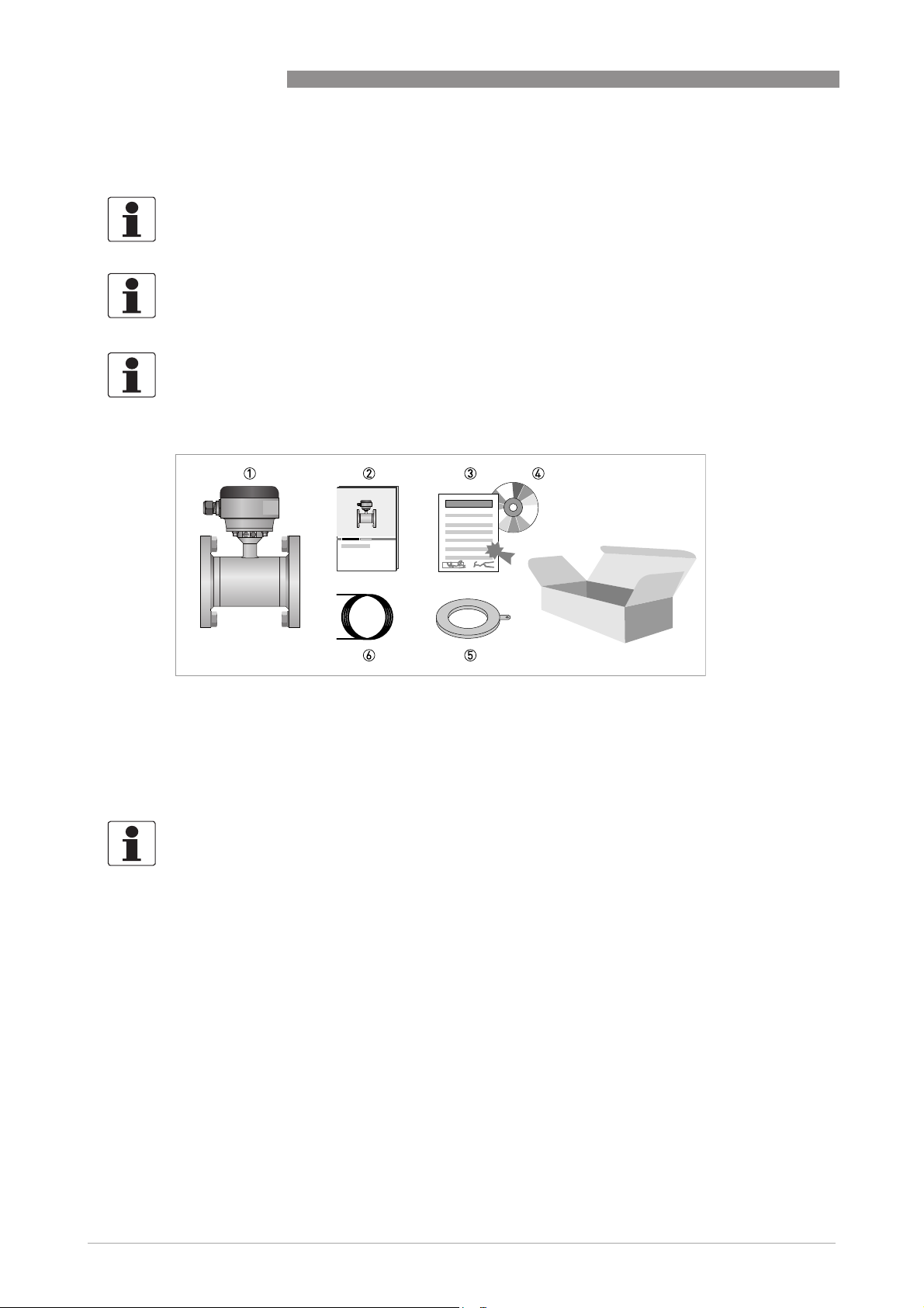
Figure 2-1: Scope of delivery
1 Ordered flowmeter
2 Product documentation
3 Factory calibration report
4 CD-ROM with product documentation
5 Grounding rings (optionally)
6 Cable (remote versions only)
INFORMATION!
Assembly materials and tools are not part of the delivery. Use the assembly materials and tools
in compliance with the applicable occupational health and safety directives.
4
www.krohne.com 04/2011 - 7309872300 - QS OPTIFLUX 5000 FL R03 en
Page 5
OPTIFLUX 5000
2.2 Device description
Your measuring device is supplied ready for operation. The factory settings for the operating
data have been made in accordance with your order specifications.
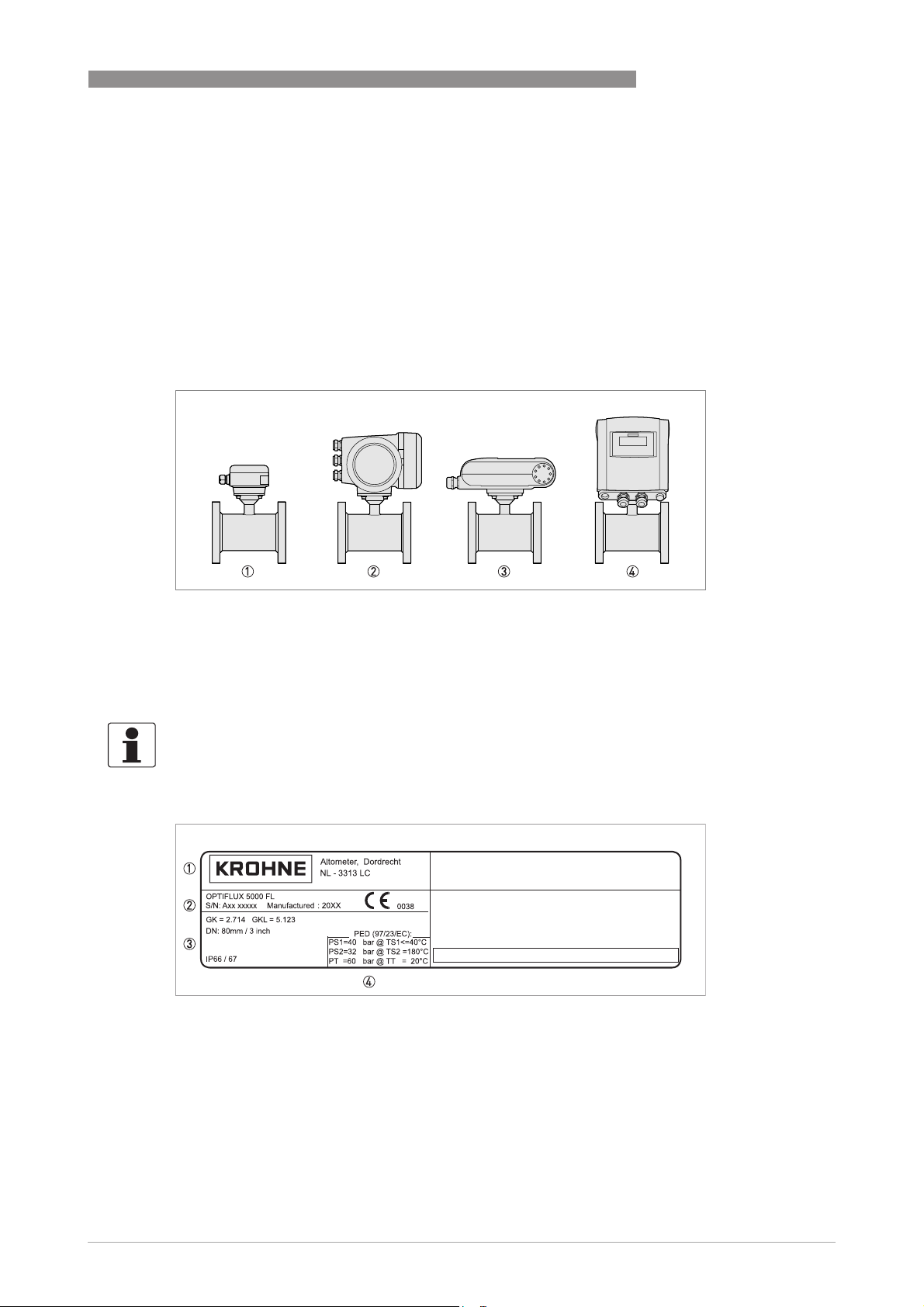
The following versions are available:
• Compact version (the signal converter is mounted directly on the measuring sensor)
• Remote version (electrical connection to the measuring sensor via field current and signal
cable)
INSTALLATION 2
1 Remote version
2 Compact version with IFC 300 signal converter
3 Compact version with IFC 100 (0°) signal converter
4 Compact version with IFC 100 (45°) signal converter
2.3 Nameplates
INFORMATION!
Look at the device nameplate to ensure that the device is delivered according to your order.
Check for the correct supply voltage printed on the nameplate.
1 Name and address of the manufacturer
2 Type designation of the flowmeter and CE sign with number(s) of notified body / bodies
3 Calibration data
4 PED data
www.krohne.com04/2011 - 7309872300 - QS OPTIFLUX 5000 FL R03 en
5
Page 6
2 INSTALLATION
2.4 Storage
• Store the device in a dry and dust-free location.
• Avoid lasting direct exposure to the sun.
• Store the device in its original packing.
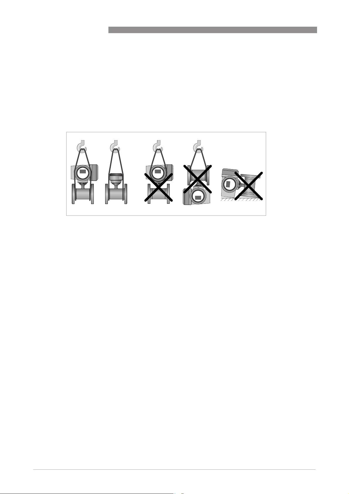
2.5 Transport
OPTIFLUX 5000
Figure 2-2: Transport
6
www.krohne.com 04/2011 - 7309872300 - QS OPTIFLUX 5000 FL R03 en
Page 7

OPTIFLUX 5000
2.6 Installation conditions
2.6.1 Inlet and outlet
Figure 2-3: Recommended inlet and outlet sections
1 ≥ 5 DN
2 ≥ 2 DN
2.6.2 Mounting position
INSTALLATION 2
Figure 2-4: Mounting position
www.krohne.com04/2011 - 7309872300 - QS OPTIFLUX 5000 FL R03 en
7
Page 8

2 INSTALLATION
2.6.3 Flange deviation
CAUTION!
Max. permissible deviation of pipe flange faces:
- L
L
max
Figure 2-5: Flange deviation
1 L
max
2 L
min
≤ 0.5 mm / 0.02"
min
OPTIFLUX 5000
2.6.4 T-section
Figure 2-6: Distance after T-sections
1 ≥ 10 DN
2.6.5 Vibration
Figure 2-7: Avoid vibrations
8
www.krohne.com 04/2011 - 7309872300 - QS OPTIFLUX 5000 FL R03 en
Page 9

OPTIFLUX 5000
2.6.6 Magnetic field
Figure 2-8: Avoid magnetic fields
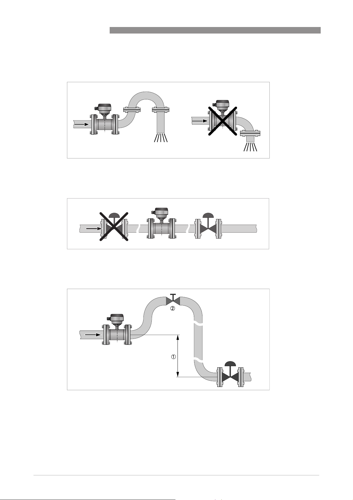
2.6.7 Bends
INSTALLATION 2
Figure 2-9: Installation in bending pipes
Figure 2-10: Installation in bending pipes
www.krohne.com04/2011 - 7309872300 - QS OPTIFLUX 5000 FL R03 en
9
Page 10
2 INSTALLATION
2.6.8 Open discharge
Figure 2-11: Installation before an open discharge
2.6.9 Control valve
OPTIFLUX 5000
Figure 2-12: Installation before control valve
2.6.10 Air venting
Figure 2-13: Air venting
1 ≥ 5 m
2 Air ventilation point
10
www.krohne.com 04/2011 - 7309872300 - QS OPTIFLUX 5000 FL R03 en
Page 11

OPTIFLUX 5000
2.6.11 Pump
Figure 2-14: Installation after pump
2.6.12 Temperatures
CAUTION!
Protect the device from direct sunlight.
Temperature range Process [°C] Ambient [°C] Process [°F] Ambient [°F]
INSTALLATION 2
min. max. min. max. min. max. min. max.
Separate flow sensor -60 180 -40 65 -76 356 -40 149
Compact + IFC 300 -60 140 -40 65 -76 284 -40 149
Compact + IFC 100 -60 140 -40 65 -76 284 -40 149
www.krohne.com04/2011 - 7309872300 - QS OPTIFLUX 5000 FL R03 en
11
Page 12

2 INSTALLATION
2.7 Mounting
2.7.1 Torques and pressures
WARNING!
Please use "not lubricated" Stainless steel A2 / 6.9 class bolts.
DN15...100
Tighten the bolts in fixed order, see picture:
• Step 1: by hand
• Step 2: approx. 25% of max. torque
• Step 3: approx. 50% of max. torque
• Step 4: approx. 80% of max. torque
• Step 5: 100% of max. torque given in table
OPTIFLUX 5000
INFORMATION!
Diameters DN80 and DN100 have 8 holes per flange, please continue in the same way to tighten
the other bolts.
CAUTION!
With the instrument, 4 PTFE gaskets are delivered (2 to be used with installation, 2 as spare). No
other gaskets are required.
EN 1092-1
Nominal size
DN [mm]
15 PN 40 4 × M 12 73.5
25 PN 40 4 × M 12 73.5
40 PN 40 4 × M 16 178
50 PN 40 4 × M 16 178
80 PN 40 8 × M 16 178
100 PN 16 8 × M 16 178
Pressure
r a t i n g
Bolts Max. torque
[Nm]
12
www.krohne.com 04/2011 - 7309872300 - QS OPTIFLUX 5000 FL R03 en
Page 13

OPTIFLUX 5000
ASME B 16.5
INSTALLATION 2
Nominal size
[inch]
1/2 300 4 × 1/2" 40
1 150 / 300 4 × 1/2" 40
1 1/2 150 / 300 4 × 1/2" 40
2 150 / 300 4 × 5/8" 97
3 150 / 300 4 × 5/8" 97
4 150 8 × 5/8" 97
Flange class
[lb]
DN150...300
Tighten the bolts:
• Step 1: approx. 50% of max. torque
• Step 2: approx. 80% of max. torque
• Step 3: 100% of max. torque given in table
Bolts Max. torque
[ftlb]
EN 1092-1
Nominal size
DN [mm]
150 PN 16 8 × M 20
200 PN 10 8 × M 20
250 PN 10 12 × M 20
300 PN 10 12 x M 20
1 Max. torque depends on the gaskets used by the end-user.
Pressure
r a t i n g
ASME B 16.5
Nominal size
[inch]
6 150 8 × 3/4"
8 150 8 × 3/4"
10 150 12 × 7/8"
12 150 12 x 7/8"
1 Max. torque depends on the gaskets used by the end-user.
Flange class
[lb]
Bolts Max. torque
[Nm]
1
1
1
1
Bolts Max. torque
[ftlb]
1
1
1
1
www.krohne.com04/2011 - 7309872300 - QS OPTIFLUX 5000 FL R03 en
13
Page 14
3 ELECTRICAL CONNECTIONS
3.1 Safety instructions
DANGER!
All work on the electrical connections may only be carried out with the power disconnected. Take
note of the voltage data on the nameplate!
DANGER!
Observe the national regulations for electrical installations!
DANGER!
For devices used in hazardous areas, additional safety notes apply; please refer to the Ex
documentation.
WARNING!
Observe without fail the local occupational health and safety regulations. Any work done on the
electrical components of the measuring device may only be carried out by properly trained
specialists.
OPTIFLUX 5000
INFORMATION!
Look at the device nameplate to ensure that the device is delivered according to your order.
Check for the correct supply voltage printed on the nameplate.
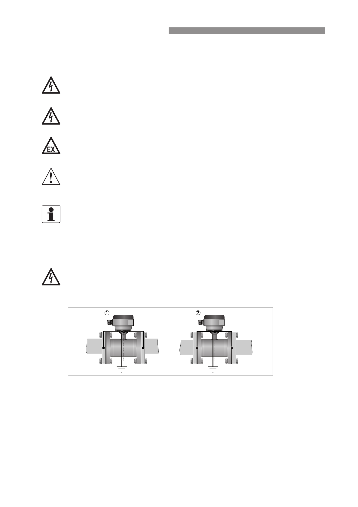
3.2 Grounding
DANGER!
The device must be grounded in accordance with regulations in order to protect personnel
against electric shocks.
Figure 3-1: Grounding
1 Metal pipelines, not internally coated. Grounding without grounding rings.
2 Metal pipelines with internal coating and non-conductive pipelines. Grounding with grounding rings.
14
www.krohne.com 04/2011 - 7309872300 - QS OPTIFLUX 5000 FL R03 en
Page 15

OPTIFLUX 5000
Figure 3-2: Grounding ring number 1
ELECTRICAL CONNECTIONS 3
Grounding ring number 1 (for type VN20):
• 3 mm / 0.1" thick (tantalum: 0.5 mm / 0.1")
3.3 Virtual reference for IFC 300 (C, W and F version)
Figure 3-3: Virtual reference
Possible if:
• ≥ DN10
• Electrical conductivity ≥ 200 µS/cm
• Electrode cable max. 50m., type DS
3.4 Connection diagrams
INFORMATION!
For the connection diagrams please refer to the documentation of the applicable converter.
www.krohne.com04/2011 - 7309872300 - QS OPTIFLUX 5000 FL R03 en
15
Page 16

4 TECHNICAL DATA
4.1 Measuring principle
An electrically conductive fluid flows inside an electrically insulated pipe through a magnetic
field. This magnetic field is generated by a current, flowing through a pair of field coils. Inside of
the fluid, a voltage U is generated:
U = v * k * B * D
U = v * k * B * D
U = v * k * B * DU = v * k * B * D
in which:
v = mean flow velocity
k = factor correcting for geometry
B = magnetic field strength
D = inner diameter of flow meter
The signal voltage U is picked off by electrodes and is proportional to the mean flow velocity v
and thus the flow rate q. A signal converter is used to amplify the signal voltage, filter it and
convert it into signals for totalising, recording and output processing.
OPTIFLUX 5000
1 Induced voltage (proportional to flow velocity)
2 Electrodes
3 Magnetic field
4 Field coils
16
www.krohne.com 04/2011 - 7309872300 - QS OPTIFLUX 5000 FL R03 en
Page 17

OPTIFLUX 5000
4.2 Dimensions and weights
Remote version
Remote version a = 77 mm / 3.1"
Remote versionRemote version
Compact version with
Compact version with
Compact version with Compact version with
IFC 300
IFC 300
IFC 300IFC 300
TECHNICAL DATA 4
b = 139 mm / 5.5" 1
c = 106 mm / 4.2"
Total height = H + a
a = 155 mm / 6.1"
b = 230 mm / 9.1" 1
c = 260 mm / 10.2"
Total height = H + a
Compact version with
Compact version with
Compact version with Compact version with
IFC 100 (0
IFC 100 (0°)
IFC 100 (0IFC 100 (0
Compact version with
Compact version with
Compact version with Compact version with
IFC 100 (45
IFC 100 (45°)
IFC 100 (45IFC 100 (45
1 The value may vary depending on the used cable glands.
)
))
)
))
a = 82 mm / 3.2"
b = 161 mm / 6.3"
c = 257 mm / 10.1" 1
Total height = H + a
a = 186 mm / 7.3"
b = 161 mm / 6.3"
c = 184 mm / 2.7" 1
Total height = H + a
www.krohne.com04/2011 - 7309872300 - QS OPTIFLUX 5000 FL R03 en
17
Page 18
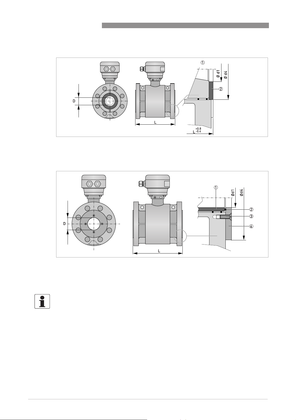
4 TECHNICAL DATA
Figure 4-1: Construction details DN15...100
1 Detail ceramics / flange / gaskets
2 PTFE sealing ring
OPTIFLUX 5000
18
Figure 4-2: Construction details DN150...300
1 Ceramic liner
2 O-ring
3 Screw
4 Grounding ring
INFORMATION!
•
All data given in the following tables are based on standard versions of the sensor only.
•
Especially for smaller nominal sizes of the sensor, the converter can be bigger than the
sensor.
•
Note that for other pressure ratings than mentioned, the dimensions may be different.
•
For full information on converter dimensions see relevant documentation.
www.krohne.com 04/2011 - 7309872300 - QS OPTIFLUX 5000 FL R03 en
Page 19

OPTIFLUX 5000
EN 1092-1
TECHNICAL DATA 4
Nominal
Dimensions [mm] Approx.
size
DN L H W D Ød1 Ød4
15 150 127 95 12 15 44 3
25 150 143 115 20 26 46 4
40 150 168 150 30 39 62 6
50 200 184 165 40 51 74 9
80 200 217 200 60 80 106 15
100 250 242 220 80 101 133 21
150 265 355 283 150 150 215 37
200 315 396 342 200 198 270 53
250 365 458 395 250 250 322 87
300 500 493 445 300 300 375 145
ASME B 16.5 150 lb
Nominal
size
inch L H W D Ød1 Ød4
1" 5.91 5.47 4.25 0.79 1.02 1.81 8.8
1½" 5.91 6.18 5 1.18 1.54 2.44 13.2
2" 7.87 6.89 6 1.57 2.01 2.91 19.8
3" 7.87 8.39 7.5 2.36 3.15 4.17 33.1
4" 9.84 9.65 9 3.15 3.98 5.24 46.3
6" 10.43 13.98 11 5.91 5.91 8.46 81.6
8" 12.4 15.59 13.5 7.80 7.80 10.63 116.8
10" 14.37 18.03 16 9.84 9.84 12.68 191.8
12" 19.69 19.41 19 11.81 11.81 14.76 366
Dimensions [inches] Approx.
weight [kg]
weight [lb]
ASME B 16.5 300 lb
Nominal
size
inch L H W D Ød1 Ød4
½" 5.91 5.0 3.74 0.47 0.59 - 6.8
1" 5.91 5.91 4.92 0.79 1.02 1.81 8.8
2" 7.87 7.20 6.50 1.57 2.01 2.91 22.9
3" 7.87 8.86 8.27 2.36 3.15 4.17 40.6
1
1½": not possible because of ASTM-NUT
": not possible because of ASTM-NUT
11
": not possible because of ASTM-NUT": not possible because of ASTM-NUT
Dimensions [inches] Approx.
weight [lb]
CAUTION!
•
Pressures at 20°C / 68°F.
•
For higher temperatures, the pressure and temperature ratings are as per ASME B16.5.
www.krohne.com04/2011 - 7309872300 - QS OPTIFLUX 5000 FL R03 en
19
Page 20

KROHNE product overview
• Electromagnetic flowmeters
• Variable area flowmeters
• Ultrasonic flowmeters
• Mass flowmeters
• Vortex flowmeters
• Flow controllers
• Level meters
• Temperature meters
• Pressure meters
• Analysis products
• Measuring systems for the oil and gas industry
• Measuring systems for sea-going tankers
Head Office KROHNE Messtechnik GmbH
Ludwig-Krohne-Str. 5
D-47058 Duisburg (Germany)
Tel.:+49 (0)203 301 0
Fax:+49 (0)203 301 10389
info@krohne.de
© KROHNE 04/2011 - 7309872300 - QS OPTIFLUX 5000 FL R03 en - Subject to change without notice.
The current list of all KROHNE contacts and addresses can be found at:
www.krohne.com
 Loading...