

Page 1

OPTIFLUX 4040 C
Quick Start
Two-wire electromagnetic flowmeter
Page 2

OPTIFLUX 4040 C
:::::::::::::::::::::::::::::
General safety notes
You can find additional information on the CD-ROM provided, in
the manual, the data sheet, special manuals and certificates.
QuickStart Manual
Installation, mounting, commissioning, and maintenance can be
performed only by trained personnel.
Responsibility for suitability and intended use of this instrument
rests solely with the user.
The supplier accepts no liability for inappropriate use by the customer.
Improper installation and operation may lead to loss of warranty.
Moreover, the "general terms and conditions" on the back of the
bill apply, which form the basis for the sales contract.
If you have to send the device back to the manufacturer or supplier, fill out the form contained on the CD-ROM and enclose it
with the device. Unless this form is completely filled out, it will
unfortunately not be possible for KROHNE to perform repair or
inspection.
Respect general and local electrical safety requirements
7.30979.21.00
2
Page 3

Visual check
OPTIFLUX 4040 C
This Quick Start is applicable to software versions:
• Display / control unit: 3.19019.xx.00
• ADC module: 3.19749.xx.00
• I/O module: 3.18748.xx.00
www.krohne.com
3
Page 4
OPTIFLUX 4040 C
:::::::::::::::::::::::::::::
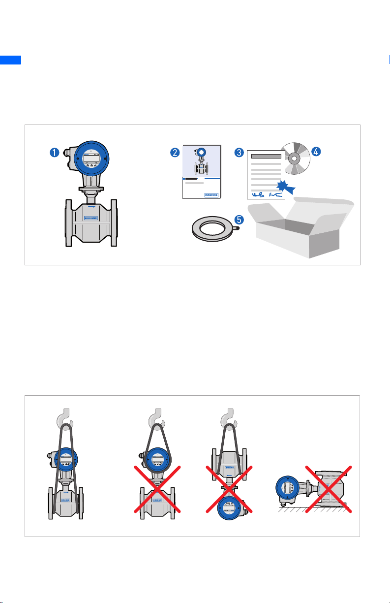
Scope of delivery
1 Flowmeter in the ordered size
2 Quick Start
3 Factory calibration report
4 CD-ROM including Handbook, Quickstart, Data Sheet
5 Grounding rings (optional)
Transport
7.30979.21.00
4
Page 5
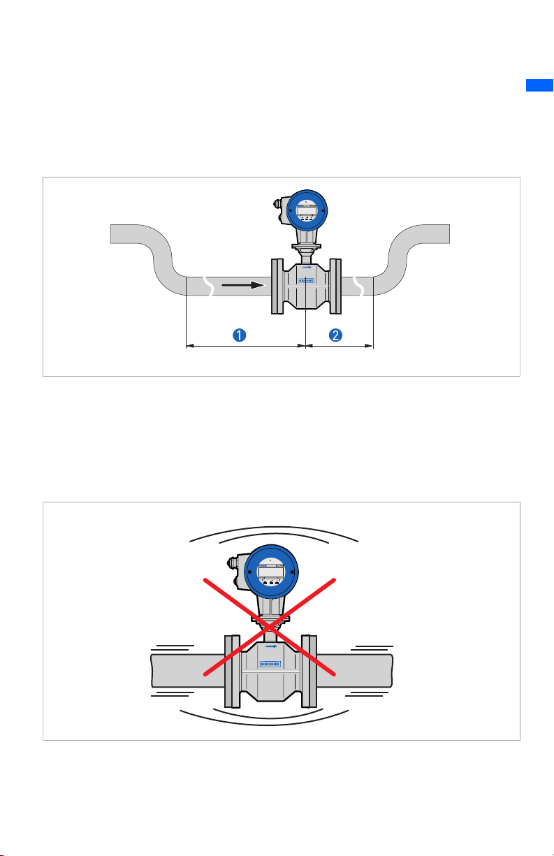
Inlet and outlet
1 ≥ 5 DN
2 ≥ 2 DN
Vibration
OPTIFLUX 4040 C
www.krohne.com
5
Page 6

OPTIFLUX 4040 C
:::::::::::::::::::::::::::::
Flange deviation
1 L
max
2 L
min
1
2
Caution!
Max. permissible deviation of pipe flange faces:
L
- L
≤ 0.5 mm
min
6
max
7.30979.21.00
Page 7

Magnetic field
OPTIFLUX 4040 C
www.krohne.com
7
Page 8

OPTIFLUX 4040 C
:::::::::::::::::::::::::::::
Bends
7.30979.21.00
8
Page 9

Open discharge
T-section
OPTIFLUX 4040 C
1 ≥ 10DN
www.krohne.com
9
Page 10

OPTIFLUX 4040 C
:::::::::::::::::::::::::::::
Air venting
1 ≥ 5 m
2 air ventilation point
2
1
Control valve
7.30979.21.00
10
Page 11

Pump
Temperature
OPTIFLUX 4040 C
1 Process temperature, -25...140°C / -13...284°F
2 Ambient temperature, -25...60°C / -13...140°F
CAUTION!
See the Handbook on the CD-ROM for the exact maximum values.
www.krohne.com
11
Page 12

OPTIFLUX 4040 C
:::::::::::::::::::::::::::::
Grounding
1 Metal pipelines, not internally coated. Grounding without grounding rings
2 Metal pipelines with internal coating, and non-conductive pipelines. Grounding with grounding
rings
3 Grounding rings
7.30979.21.00
12
Page 13

Torques and pressures
Pressure in bar and torque in Nm (EN 1092-1 and ASME B 16.5)
OPTIFLUX 4040 C
Size of
measuring tube
DN 10 DN 15 PN 40 ≤ 40 7,6
DN 15 DN 15 PN 40 ≤ 40 9,3
DN 20 DN 20 PN 40 ≤ 40 16
DN 25 DN 25 PN 40 ≤ 40 22
DN 50 DN 50 PN 40 ≤ 40 55
DN 65 DN 65 PN 16 ≤ 16 51
DN 80 DN 80 PN 40 ≤ 40 47
DN 100 DN 100 PN 16 ≤ 16 39
DN 125 DN 125 PN 16 ≤ 16 53
DN 150 DN 150 PN 16 ≤ 16 68
3/8" 1/2" 150 lb ≤ 19 3,5
1/2" 1/2" 150 lb ≤ 19 3,5
3/4" 3/4" 150 lb ≤ 19 4,8
1" 1" 150 lb ≤ 19 6,7
2" 2" 150 lb ≤ 19 24
3" 3" 150 lb ≤ 16 43
4" 4" 150 lb ≤ 16 34
6" 6" 150 lb ≤ 16 61
Pipe flanges Max. allowable operating
pressure
Meter size Rating/Class [bar] [Nm]
Max. allowable torque
www.krohne.com
13
Page 14

OPTIFLUX 4040 C
:::::::::::::::::::::::::::::
Max. torque:
• Step 1: approx. 50% of max. torque
• Step 2: approx. 80% of max. torque
• Step 3: 100% of max. torque given in table before
Limits / vacuum load
PFA liner: No limits for vacuum load.
PTFE liner: see manual on CD-Rom.
7.30979.21.00
14
Page 15

OPTIFLUX 4040 C
Menu
Menu concept
Measuring mode Data
→^1.0 →^Operation →
1.1 Full scale
1.2 Time constant
1.3 L.F. Cutoff
1.4 Display
1.5 Current output
1.6 Pulse output
1.7 Status output
2.0 Test
2.1 Test Q
2.2 Hardware info
3.0 Installation
3.1 Language
3.2 Flow meter
3.3 Zero set
3.4 Application
3.5 Hardware
^
3.6 Hart
4.0 Reset
4.1 Error reset
4.2 Counter reset
↑ ↑ →
www.krohne.com
^
15
Page 16

OPTIFLUX 4040 C
:::::::::::::::::::::::::::::
Contact
KROHNE Altometer
Kerkeplaat 12
3313 LC Dordrecht
Postbus 110
3300 AC Dordrecht, the Netherlands
www.krohne.com
7.30979.21.00
16
 Loading...