

KROHNE OPTIFLUX 2000 Specifications
Technical Datasheet
Technical Datasheet
OPTIFLUX 2000
OPTIFLUX 2000
OPTIFLUX 2000OPTIFLUX 2000
Technical DatasheetTechnical Datasheet
Electromagnetic flow sensor
•
For all water and wastewater applications
•
Wide range of approvals for potable water
•
Robust, fully welded construction
The documentation is only complete when used in combination with the relevant
documentation for the signal converter.
© KROHNE 11/2017 - 4000086806 - TD OPTIFLUX 2000 R10 en

CONTENTS
OPTIFLUX 2000
1 Product features 3
1.1 Reliable solution for the water and wastewater industry ............................................... 3
1.2 Options.............................................................................................................................. 5
1.3 Measuring principle.......................................................................................................... 8
2 Technical data 9
2.1 Technical data................................................................................................................... 9
2.2 Legal metrology.............................................................................................................. 16
2.2.1 OIML R49 ............................................................................................................................... 16
2.2.2 MID Annex III (MI-001)........................................................................................................... 18
2.3 Measuring accuracy ....................................................................................................... 20
2.4 Pressure derating........................................................................................................... 21
2.5 Vacuum load ................................................................................................................... 23
2.6 Dimensions and weights ................................................................................................ 24
3 Installation 28
3.1 Intended use ................................................................................................................... 28
3.2 General notes on installation ......................................................................................... 28
3.2.1 Vibration ................................................................................................................................ 28
3.2.2 Magnetic field........................................................................................................................ 28
3.3 Installation conditions ....................................................................................................29
3.3.1 Inlet and outlet...................................................................................................................... 29
3.3.2 Bends in 2 or 3 dimensions................................................................................................... 29
3.3.3 T-section ............................................................................................................................... 30
3.3.4 Bends .................................................................................................................................... 30
3.3.5 Open feed or discharge......................................................................................................... 31
3.3.6 Flange deviation.................................................................................................................... 31
3.3.7 Pump ..................................................................................................................................... 31
3.3.8 Control valve ......................................................................................................................... 32
3.3.9 Air venting and vacuum forces ............................................................................................. 32
3.3.10 Mounting position................................................................................................................ 33
3.4 Mounting......................................................................................................................... 34
3.4.1 Torques and pressures......................................................................................................... 34
4 Electrical connections 37
4.1 Safety instructions.......................................................................................................... 37
4.2 Grounding ....................................................................................................................... 37
4.3 Virtual reference for IFC 300 (C, W and F version) ....................................................... 39
4.4 Connection diagrams ..................................................................................................... 39
2
www.krohne.com 11/2017 - 4000086806 - TD OPTIFLUX 2000 R10 en
OPTIFLUX 2000
PRODUCT FEATURES
1.1 Reliable solution for the water and wastewater industry
The OPTIFLUX 2000
OPTIFLUX 2000 is designed to meet the demands for all water and waste water applications
OPTIFLUX 2000OPTIFLUX 2000
including groundwater, potable water, waste water, sludge and sewage, industry water and salt
water.
The OPTIFLUX 2000 has a field proven and unsurpassed lifetime. This is assured by the fully
welded construction, full bore pipe, absence of moving parts and wear resistant liner materials.
The sensor has the widest diameter range available in the market: from DN25 up to DN3000.
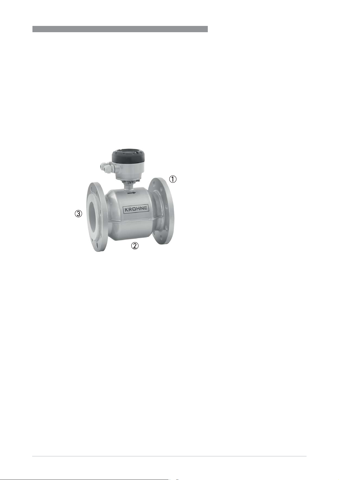
1
1 Robust fully welded construction
2 Diameter range: DN25...DN3000
3 PP, PO and hard rubber liners
www.krohne.com11/2017 - 4000086806 - TD OPTIFLUX 2000 R10 en
3

1
PRODUCT FEATURES
Highlights
• Rugged liners suitable for any water and wastewater application
• Proven and unsurpassed lifetime, huge installed base
• Tamper proof, fully welded construction, also available in customer specific constructions
• Drinking water approvals including KTW, KIWA, ACS, DVGW, NSF, WRAS
• Suitable for subsoil installation and constant flooding (IP68)
• Bi-directional flow metering
• Compliant with requirements for custody transfer
(MID MI-001, OIML R49, ISO 4064, EN 14154)
• Standard in house wet calibration of sensors up to diameter DN3000
• Easy installation and commissioning
• No grounding rings with virtual reference option on IFC 300
• In-situ verification with OPTICHECK
• Extensive diagnostic capabilities
• Maintenance-free
Industries
• Water
• Wastewater
• Pulp & Paper
• Minerals & Mining
• Iron, Steel & Metals
• Power
OPTIFLUX 2000
Applications
• Water abstraction
• Water purification and desalination
• Drinking water distribution networks
• Revenue metering or billing
• Leakage detection
• Irrigation
• Industry water
• Cooling water
• Wastewater
• Sewage and sludge
• Sea water
4
www.krohne.com 11/2017 - 4000086806 - TD OPTIFLUX 2000 R10 en
OPTIFLUX 2000
1.2 Options
The reliable solution for the water and wastewater industry
From standard to customized
From standard to customized
From standard to customizedFrom standard to customized
For easy ordering the standard range of the
OPTIFLUX 2000 covers all popular sizes, flange
materials and connections (ASME, EN, JIS, AWWA).
But KROHNE does not stop here. Our extensive
engineering department is dedicated to provide
solutions for all specifications not covered by our
standard range. Requests for special sizes, flange
connections, pressure ratings, building lengths, and
materials, will always get a serious review.
Whenever possible we will engineer a flow meter
that fits your application.
The is designed to meet the demands for all water
and waste water applications including
groundwater, potable water, waste water, sludge
and sewage, industry water and salt water.
PRODUCT FEATURES
1
The has a field proven and unsurpassed lifetime
assured by the fully welded housing, full bore pipe
construction, absence of moving parts and wear
resistant liner materials.
www.krohne.com11/2017 - 4000086806 - TD OPTIFLUX 2000 R10 en
5
1
PRODUCT FEATURES
OPTIFLUX 2000
Easy installation
Easy installation
Easy installationEasy installation
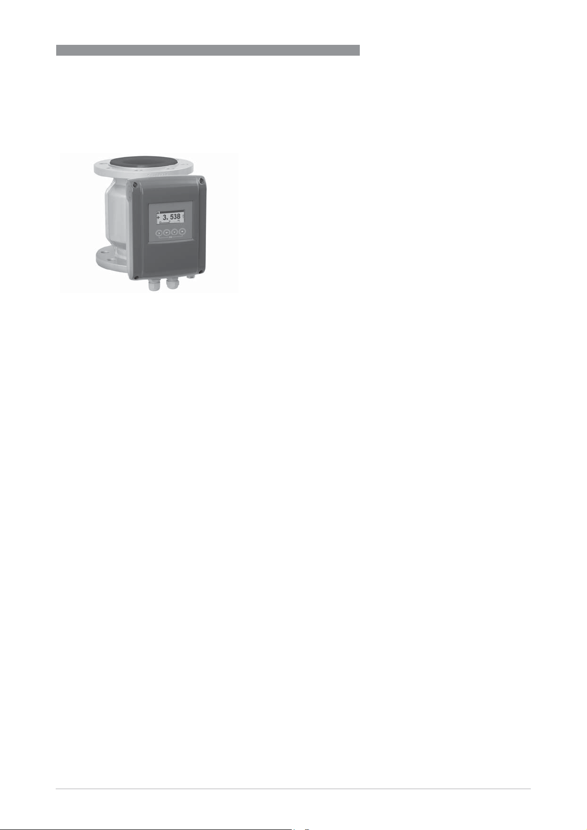
Fitting the OPTIFLUX 2000 is easy with the flanged
design and standard ISO insertion lengths. To
further ease the operation, the OPTIFLUX 2000 can
be installed without filters and straighteners. Even
grounding rings are not required with the patented
"Virtual Reference"
"Virtual Reference" option on the IFC 300 converter.
"Virtual Reference""Virtual Reference"
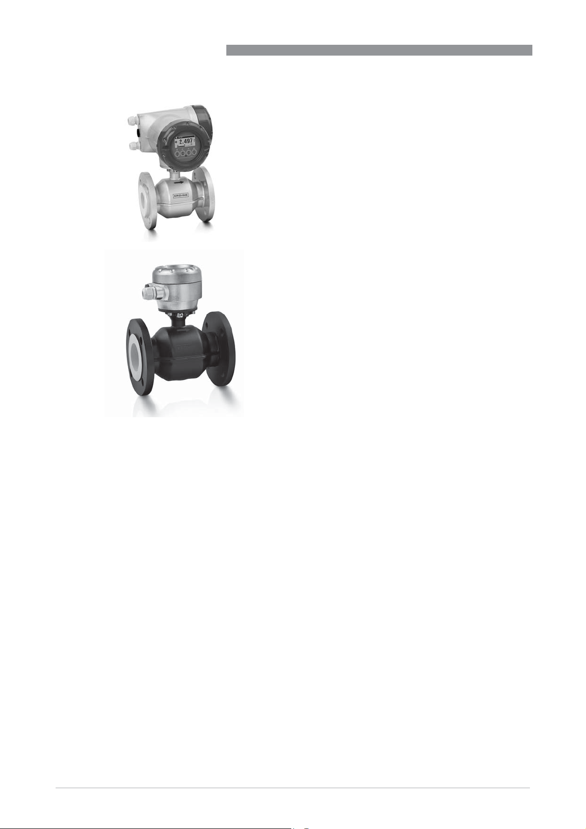
IP68
IP68
IP68IP68
Installation in measurement chambers subject to
(constant) flooding is possible with the IP68 rated
version. The chambers can even be completely
surpassed if the IP68 version is combined with our
special subsoil coating, allowing the OPTIFLUX 2000
to be installed directly in the ground.
6
www.krohne.com 11/2017 - 4000086806 - TD OPTIFLUX 2000 R10 en

OPTIFLUX 2000
PRODUCT FEATURES
Custody transfer
Custody transfer
Custody transferCustody transfer
In combination with the IFC 300 converter the
OPTIFLUX 2000 is suitable for custody transfer
applications. It meets the requirements of OIML R49
and can be verified according to Annex MI-001 of the
Measuring Instruments Directive (MID)
All water meters for legal metrology purposes in
Europe require certification under the MID. The EC
type examination certificate for the is valid for the
compact and the remote version and applies for
forward and reverse flow.
1
www.krohne.com11/2017 - 4000086806 - TD OPTIFLUX 2000 R10 en
7
1
PRODUCT FEATURES
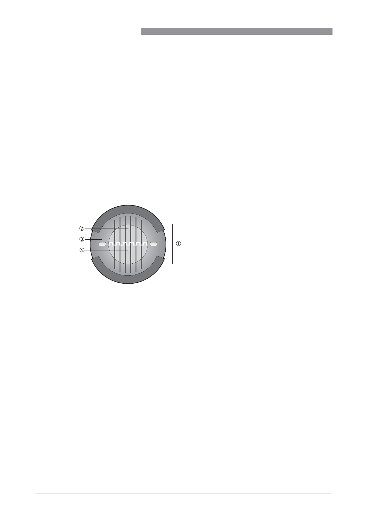
1.3 Measuring principle
An electrically conductive fluid flows inside an electrically insulated pipe through a magnetic
field. This magnetic field is generated by a current, flowing through a pair of field coils.
Inside of the fluid, a voltage U is generated:
U = v * k * B * D
U = v * k * B * D
U = v * k * B * DU = v * k * B * D
in which:
v = mean flow velocity
k = factor correcting for geometry
B = magnetic field strength
D = inner diameter of flowmeter
The signal voltage U is picked off by electrodes and is proportional to the mean flow velocity v
and thus the flow rate Q. A signal converter is used to amplify the signal voltage, filter it and
convert it into signals for totalizing, recording and output processing.
OPTIFLUX 2000
Figure 1-1: Measuring principle
1 Field coils
2 Magnetic field
3 Electrodes
4 Induced voltage (proportional to flow velocity)
8
www.krohne.com 11/2017 - 4000086806 - TD OPTIFLUX 2000 R10 en

OPTIFLUX 2000
TECHNICAL DATA
2.1 Technical data
•
The following data is provided for general applications. If you require data that is more
relevant to your specific application, please contact us or your local sales office.
•
Additional information (certificates, special tools, software,...) and complete product
documentation can be downloaded free of charge from the website (Downloadcenter).
Measuring system
Measuring principle Faraday's law of induction
Application range Electrically conductive fluids
Measured value
Measured value
Measured valueMeasured value
Primary measured value Flow velocity
Secondary measured value Volume flow
Design
Features Fully welded maintenance-free sensor.
Large diameter range DN25...3000
Rugged liners approved for drinking water.
Large standard range but also available in customer specific diameter, length and
pressure rating.
Modular construction The measurement system consists of a flow sensor and a signal converter. It is
Compact version With signal converter IFC 050: OPTIFLUX 2050 C
Remote version In wall (W) mount version with signal converter IFC 050: OPTIFLUX 2050 W
Nominal diameter With signal converter IFC 050: DN25...1200 / 1…48"
available as compact and as separate version. Additional information can be found
in the documentation of the signal converter.
With signal converter IFC 100: OPTIFLUX 2100 C
With signal converter IFC 300: OPTIFLUX 2300 C
In wall (W) mount version with signal converter IFC 100: OPTIFLUX 2100 W
In field (F), wall (W) or rack ( R) mount version with signal converter IFC 300:
OPTIFLUX 2300 F, W or R
With signal converter IFC 100: DN25...1200 / 1…48"
With signal converter IFC 300: DN25...3000 / 1…120"
2
www.krohne.com11/2017 - 4000086806 - TD OPTIFLUX 2000 R10 en
9

2
TECHNICAL DATA
Measuring accuracy
Reference conditions Medium: water
Temperature: +10...+30°C / +50...+86°F
Operating pressure: 1 bar / 14.5 psi
Inlet section t 5DN
Electrical conductivity: t 300 PS/cm
Maximum measuring error IFC 050: down to 0.5% of the measured value ±1 mm/s
IFC 100: down to 0.3% of the measured value ±1 mm/s
IFC 300: down to 0.2% of the measured value ±1 mm/s
The maximum measuring error depends on the installation conditions.
For detailed information refer to
Repeatability ±0.1% of the measured value, minimum 1 mm/s
Calibration / Verification Standard:
MID Annex MI-001
(Directive 2004/22/EC)
OIML R49 Certificate of conformity to OIML R49
Standard:
Standard:Standard:
2 point calibration by a direct volume comparison.
Optional:
Optional:
Optional:Optional:
Verification to Measurement Instrument Directive (MID), Annex MI-001.
Standard: Verification at Ratio (Q3/Q1) = 80, Q3 t 2m/s
Optional: Verification at Ratio (Q3/Q1) > 80 on request
Only in combination with the signal converter IFC 300.
EC-Type examination certificate to MID Annex MI-001
EC-Type examination certificate to MID Annex MI-001
EC-Type examination certificate to MID Annex MI-001EC-Type examination certificate to MID Annex MI-001
Only in combination with the signal converter IFC 300.
Diameter range: DN25...1600
Forward and reverse (bi-directional) flow
Liquid temperature range: +0.1°C / +50°C
For detailed information refer to
Certificate of conformity to OIML R49
Certificate of conformity to OIML R49Certificate of conformity to OIML R49
Only in combination with the signal converter IFC 300.
Diameter range Class 1:DN65...1600
Forward and reverse (bi-directional) flow
Liquid temperature range: +0.1°C / +50°C
For detailed information refer to
Measuring accuracy
Legal metrology
Legal metrology
on page 16.
Class 2: DN25...50
on page 16.
OPTIFLUX 2000
on page 20.
10
www.krohne.com 11/2017 - 4000086806 - TD OPTIFLUX 2000 R10 en

OPTIFLUX 2000
TECHNICAL DATA
Operating conditions
Temperature
Temperature
TemperatureTemperature
For detailed information in pressure / temperature refer to
For Ex versions different temperatures are valid. Please refer to the relevant Ex
documentation for details.
Process temperature Hard rubber liner: -5...+80°C / +23...+176°F
Polypropylene liner: -5...+90°C / +23...+194°F
Polyolefin liner: -5...+80°C / +23...+176°F
Ambient temperature Standard
Protect electronics against self-heating at ambient temperatures above +55°C / +131°F.
Storage temperature -50...+70°C / -58...+158°F
Measuring range
Measuring range -12...+12 m/s / -40...+40 ft/s
Measuring rangeMeasuring range
Standard (with aluminum signal converter housing): standard flanges
StandardStandard
-20…+65°C / -4…+149°F
Option
Option (with aluminum signal converter housing): low temperature carbon steel
OptionOption
flanges or stainless steel flanges
-40…+65°C / -40…+149°F
Option
Option (with stainless steel signal converter housing): low temperature carbon
OptionOption
steel flanges or stainless steel flanges
-40...+55°C / -40…+130°F
Pressure derating
on page 21.
2
www.krohne.com11/2017 - 4000086806 - TD OPTIFLUX 2000 R10 en
11

2
TECHNICAL DATA
Pressure
Pressure
PressurePressure
For detailed information in pressure / temperature refer to
EN 1092-1 DN2200...3000: PN2.5
DN1200...2000: PN6
DN200...1000: PN10
DN65 and DN100...150: PN16
DN25...50 and DN80: PN40
Other pressures on request
ASME B16.5 1...24": 150 & 300 lb RF
Other pressures on request
JIS DN50...1000 / 2...40": 10 K
DN25...40 / 1...1½": 20 K
Other pressures on request
AWWA
(class B or D FF)
DIN PN16 - 6 bar rated; DN700...2000
Vacuum load For detailed information refer to
Pressure loss Negligible
Chemical properties
Chemical properties
Chemical propertiesChemical properties
Physical condition Electrically conductive liquids
Electrical conductivity Standard: t 5 μS/cm
Permissible gas content (volume) IFC 050: d 3%
Permissible solid content
(volume)
Option:
Option:
Option:Option:
DN700...1000 / 28...40": d 10 bar / 145 psi
DN1200...2000 / 48...80": d 6 bar / 87 psi
PN10 - 6 bar rated; DN700...2000
PN6 - 2 bar rated; DN700...2000
Demineralised water: t 20 μS/cm
IFC 100: d 3%
IFC 300: d 5%
IFC 050: d 10%
IFC 100: d 10%
IFC 300: d 70%
Pressure derating
on page 21.
Vacuum load
OPTIFLUX 2000
on page 23.
12
www.krohne.com 11/2017 - 4000086806 - TD OPTIFLUX 2000 R10 en
 Loading...