

KROHNE OPTIFLUX2000, OPTIFLUX4000, OPTIFLUX5000, OPTIFLUX-6000, OPTIFLUX-7300-IFC User Manual
Page 1

OPTIFLUX
OPTIFLUX
OPTIFLUXOPTIFLUX
Ex addendum
Supplementary instructions
Supplementary instructions
Supplementary instructions Supplementary instructions
© KROHNE 07/2010 - 7309482600 - AD EX IFC 300 R06 en
Page 2

CONTENTS
OPTIFLUX
1 Introduction 4
1.1 Safety instructions from the manufacturer ..................................................................... 4
1.1.1 Disclaimer ............................................................................................................................... 4
1.1.2 Product liability and warranty ................................................................................................ 5
1.1.3 Information concerning the documentation........................................................................... 5
1.1.4 Warnings and symbols used................................................................................................... 6
1.1.5 Manufacturer .......................................................................................................................... 6
1.2 Safety instructions for the operator................................................................................. 7
1.3 Approvals.......................................................................................................................... 8
1.4 OPTIFLUX 2000 / 4000 ...................................................................................................... 9
1.4.1 Compact versions ................................................................................................................... 9
1.4.2 Field versions........................................................................................................................ 10
1.5 OPTIFLUX 5000 ............................................................................................................... 11
1.5.1 Compact versions ................................................................................................................. 11
1.5.2 Field versions........................................................................................................................ 12
1.6 OPTIFLUX 6000 ............................................................................................................... 13
1.6.1 Compact versions ................................................................................................................. 13
1.6.2 Field versions........................................................................................................................ 14
1.7 OPTIFLUX 7000 ............................................................................................................... 15
1.7.1 Compact versions ................................................................................................................. 15
1.8 IFC 300 F ......................................................................................................................... 16
1.9 Marking labels ................................................................................................................ 17
2 Temperature limits 18
2.1 OPTIFLUX 2000 / 4000 .................................................................................................... 18
2.1.1 Compact versions ................................................................................................................. 18
2.1.2 Field versions........................................................................................................................ 20
2.2 OPTIFLUX 5000 ............................................................................................................... 22
2.2.1 Compact versions ................................................................................................................. 22
2.2.2 Field versions........................................................................................................................ 23
2.3 OPTIFLUX 6000 ............................................................................................................... 24
2.3.1 Compact versions ................................................................................................................. 24
2.3.2 Field versions........................................................................................................................ 25
2.4 OPTIFLUX 7000 ............................................................................................................... 26
2.4.1 Compact versions ................................................................................................................. 26
2.5 IFC 300 F ......................................................................................................................... 26
3 Connection diagrams for field versions 27
3.1 Signal cable A ................................................................................................................. 27
3.2 Signal cable B ................................................................................................................ 28
3.3 Equipotential bonding..................................................................................................... 29
3.4 Signal cable connections................................................................................................ 30
2
www.krohne.com 07/2010 - 7309482600 - AD EX IFC 300 R06 en
Page 3

OPTIFLUX
CONTENTS
4 Electrical connections 31
4.1 Installation instructions ................................................................................................. 31
4.2 Connection of IFC 300..................................................................................................... 33
4.3 Input/output connections ............................................................................................... 35
5 Maintenance and service 37
5.1 Maintenance ................................................................................................................... 37
5.2 Before and after opening................................................................................................ 37
5.3 Replacement of mains fuse............................................................................................ 38
6 Notes 39
www.krohne.com07/2010 - 7309482600 - AD EX IFC 300 R06 en
3
Page 4

1 INTRODUCTION
1.1 Safety instructions from the manufacturer
1.1.1 Disclaimer
The manufacturer will not be liable for any damage of any kind by using its product, including,
but not limited to direct, indirect, incidental, punitive and consequential damages.
This disclaimer does not apply in case the manufacturer has acted on purpose or with gross
negligence. In the event any applicable law does not allow such limitations on implied warranties
or the exclusion of limitation of certain damages, you may, if such law applies to you, not be
subject to some or all of the above disclaimer, exclusions or limitations.
Any product purchased from the manufacturer is warranted in accordance with the relevant
product documentation and our Terms and Conditions of Sale.
The manufacturer reserves the right to alter the content of its documents, including this
disclaimer in any way, at any time, for any reason, without prior notification, and will not be liable
in any way for possible consequences of such changes.
OPTIFLUX
4
www.krohne.com 07/2010 - 7309482600 - AD EX IFC 300 R06 en
Page 5

OPTIFLUX
1.1.2 Product liability and warranty
The operator shall bear responsibility for the suitability of the device for the specific purpose.
The manufacturer accepts no liability for the consequences of misuse by the operator. Improper
installation and operation of the devices (systems) will cause the warranty to be void. The
respective "Standard Terms and Conditions" which form the basis for the sales contract shall
also apply.
1.1.3 Information concerning the documentation
To prevent any injury to the user or damage to the device it is essential that you read the
information in this document and observe applicable national standards, safety requirements
and accident prevention regulations.
If this document is not in your native language and if you have any problems understanding the
text, we advise you to contact your local office for assistance. The manufacturer can not accept
responsibility for any damage or injury caused by misunderstanding of the information in this
document.
This document is provided to help you establish operating conditions, which will permit safe and
efficient use of this device. Special considerations and precautions are also described in the
document, which appear in the form of underneath icons.
INTRODUCTION 1
www.krohne.com07/2010 - 7309482600 - AD EX IFC 300 R06 en
5
Page 6
1 INTRODUCTION
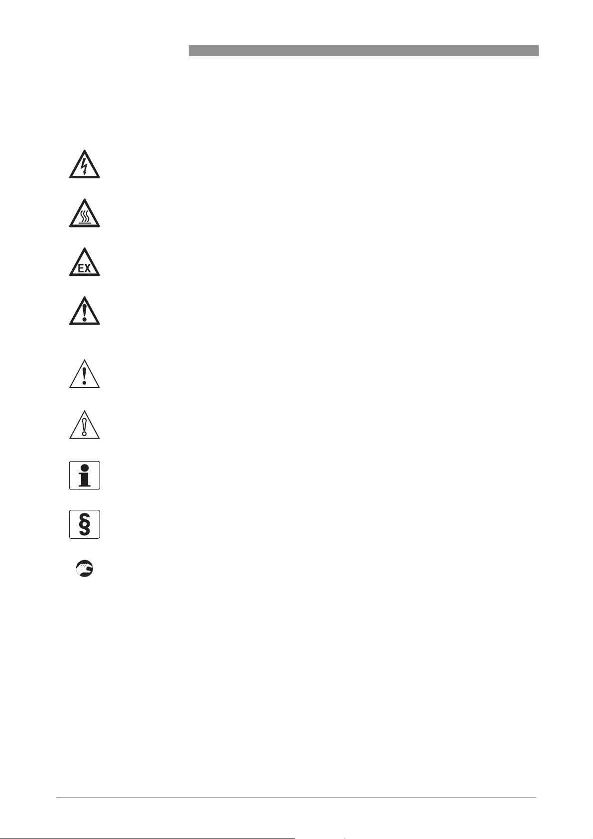
1.1.4 Warnings and symbols used
Safety warnings are indicated by the following symbols.
DANGER!
This information refers to the immediate danger when working with electricity.
DANGER!
This warning refers to the immediate danger of burns caused by heat or hot surfaces.
DANGER!
This warning refers to the immediate danger when using this device in a hazardous atmosphere.
DANGER!
These warnings must be observed without fail. Even partial disregard of this warning can lead to
serious health problems and even death. There is also the risk of seriously damaging the device
or parts of the operator's plant.
OPTIFLUX
WARNING!
Disregarding this safety warning, even if only in part, poses the risk of serious health problems.
There is also the risk of damaging the device or parts of the operator's plant.
CAUTION!
Disregarding these instructions can result in damage to the device or to parts of the operator's
plant.
INFORMATION!
These instructions contain important information for the handling of the device.
LEGAL NOTICE!
This note contains information on statutory directives and standards.
• HANDLING
HANDLING
HANDLINGHANDLING
This symbol designates all instructions for actions to be carried out by the operator in the
specified sequence.
i RESULT
RESULT
RESULTRESULT
This symbol refers to all important consequences of the previous actions.
1.1.5 Manufacturer
This instrument is developed and manufactured by:
KROHNE Altometer
Kerkeplaat 12
3313 LC Dordrecht
The Netherlands
6
www.krohne.com 07/2010 - 7309482600 - AD EX IFC 300 R06 en
Page 7

OPTIFLUX
For information, maintenance or service please contact your nearest local KROHNE
representative.
1.2 Safety instructions for the operator
WARNING!
•
Do not change the device. Unauthorized changes affect the explosion safety of the devices.
•
The prescriptions and regulations as well as the electrical data described in the EC type
examination certificate must be obeyed.
•
Beside the instructions for electrical installations in non-hazardous locations according to
the applicable national standard (equivalent to HD 384 or IEC 60364, e.g. VDE 0100),
especially the regulations in EN 60079-14 "Electrical installations in hazardous locations",
equivalent national standard (e.g. DIN VDE 0165 Part 1) or dust hazardous areas such as EN
61241-14 must be complied with!
•
Installation, establishment, utilization and maintenance are only allowed to be executed by
personnel with an education in explosion safety!
These additional instructions are an extension to the handbook. All technical information as
described in the handbook is applicable, when not specifically excluded, completed or replaced
by the instructions in these additional instructions.
INTRODUCTION 1
www.krohne.com07/2010 - 7309482600 - AD EX IFC 300 R06 en
7
Page 8

1 INTRODUCTION
1.3 Approvals
The flowmeter system consists of a flow sensor and a signal converter. The approval numbers
are:
compact versions:
• OPTIFLUX 2300 C (= OPTIFLUX 2000 + IFC 300):
KEMA 04 ATEX 2077 X
• OPTIFLUX 4300 C (= OPTIFLUX 4000 + IFC 300):
KEMA 04 ATEX 2077 X
• OPTIFLUX 5300 C (= OPTIFLUX 5000 + IFC 300):
KEMA 04 ATEX 2127 X
• OPTIFLUX 6300 C (= OPTIFLUX 6000 + IFC 300):
KEMA 05 ATEX 2214 X
• OPTIFLUX 7300 SW/C and FL/C (= OPTIFLUX 7000 + IFC 300):
KEMA 10 ATEX 0105 X
field versions:
• OPTIFLUX 2000 F + IFC 300 F:
KEMA 04 ATEX 2125 X + KEMA 04 ATEX 2166
• OPTIFLUX 4000 F + IFC 300 F:
KEMA 04 ATEX 2125 X + KEMA 04 ATEX 2166
• OPTIFLUX 5000 F + IFC 300 F:
KEMA 04 ATEX 2126 X + KEMA 04 ATEX 2166
• OPTIFLUX 6000 F + IFC 300 F:
KEMA 07 ATEX 0020 X + KEMA 04 ATEX 2166
OPTIFLUX
INFORMATION!
All type examination certificates can be downloaded from the website.
8
www.krohne.com 07/2010 - 7309482600 - AD EX IFC 300 R06 en
Page 9

OPTIFLUX
1.4 OPTIFLUX 2000 / 4000
1.4.1 Compact versions
OPTIFLUX 2300 C / 4300 C is certified as a group II, category 2 GD equipment, if fitted with an IFC
300 signal converter without Ex ia signal in/outputs or as a group II, category 2 (1) GD equipment,
if fitted with a signal converter with Ex ia signal in/outputs.
It is therefore suitable for installation in gas hazardous areas zone 1 or 2, gas group IIC,
temperature class T6 (or T5)...T3 and dust hazardous areas zone 21 or zone 22, surface
temperature T85...150°C. Additionally, the Ex ia signal inputs/outputs of the signal converter
may run or originate from a Zone 0 Gas hazardous area.
Converter housing, connection compartment:
Converter housing, connection compartment: with power supply (terminals L, N / L+, L-) and I/O
Converter housing, connection compartment: Converter housing, connection compartment:
connections (terminals A, A+, A-, B, B-, C, C-, D and D-):
Ex e (Increased safety), optionally: Ex d (Flameproof Enclosure). For certain versions of the
signal converter the terminals A, A+, A-, B, B-, C, C-, D and D- are additionally Ex ia (Intrinsic
safety). Consult the table with the CG numbers for more details.
Converter housing, electronics compartment:
Converter housing, electronics compartment: Ex d (Flameproof enclosure).
Converter housing, electronics compartment:Converter housing, electronics compartment:
EEx marking OPTIFLUX 2300 C / 4300 C:
INTRODUCTION 1
Nominal
Nominal
Nominal Nominal
diameter
diameter
diameterdiameter
2.5...15 ("me")
10...20 ("me")
25...150 ("d") EEx de [ia] IIC T6...T3 T85...150°C EEx d [ia] IIC T6...T3 T85...150°C
200...300 ("qe") EEx dqe [ia] IIC T6...T3 T85...150°C EEx dqe [ia] IIC T6...T3 T85...150°C
350...3000 ("e") EEx de [ia] IIC T6...T3 T85...150°C EEx de [ia] IIC T6...T3 T85...150°C
Optional:
Optional:
Optional:Optional:
25...150 ("qe") EEx dqe [ia] IIC T5...T3 T85...150°C EEx dqe [ia] IIC T5...T3 T85...150°C
EEx e connection compartment,
EEx e connection compartment,
EEx e connection compartment,EEx e connection compartment,
II 2 GD or II 2(1) GD
EEx dme [ia] IIC T6...T3 T85...150°C EEx dme [ia] IIC T6...T3 T85...150°C
EEx d connection compartment,
EEx d connection compartment,
EEx d connection compartment,EEx d connection compartment,
II 2 GD or II 2(1) GD
www.krohne.com07/2010 - 7309482600 - AD EX IFC 300 R06 en
9
Page 10

1 INTRODUCTION
1.4.2 Field versions
OPTIFLUX 2000 F / 4000 F is certified as group II, category 2 GD equipment for gas hazardous
areas zone 1 and 2, gas group IIC, temperature classes T6 (or T5) ... T3 and dust hazardous areas
zone 21 and 22, surface temperature T85…150/160/180°C.
The connection box contains terminals for the connection of the field current and electrode
circuits:
Field current circuit
Field current circuit, in type of protection "Increased safety" (Ex e), terminals 7, 8 and 9:
Field current circuitField current circuit
U < 40 V (switched DC voltage, alternately +40 and -40 V), I = 125 mA (injected square wave
current),
Electrode terminals
Electrode terminals, in type of protection "Intrinsic safety" (Ex ia), terminals 1, 2, 3 and 4:
Electrode terminalsElectrode terminals
= 20 V, Ii = 175 mA, Ci ≈ 0 nF, Li ≈ 0 mH.
U
i
The before mentioned intrinsically safe circuits shall, from the safety point of view, be
considered to be connected to ground.
The cable gland
cable gland for the electrode circuit is - as intrinsic safe circuit - marked with a blue O-ring.
cable glandcable gland
EEx marking OPTIFLUX 2000 F / 4000 F:
Nominal diameter
Nominal diameter II 2 GD
Nominal diameterNominal diameter
10...20 ("me") EEx me ia IIC T6...T3 T85...150°C
25...150 ("d") EEx de ia IIC T6...T3 T85...180°C
200...300 ("qe") EEx qe ia IIC T6...T3 T85...150°C
350...3000 ("e") EEx e ia IIC T6...T3 T85...160°C
Optional:
Optional:
Optional:Optional:
25...150 ("qe") EEx qe ia IIC T5...T3 T85...180°C
OPTIFLUX
10
www.krohne.com 07/2010 - 7309482600 - AD EX IFC 300 R06 en
Page 11

OPTIFLUX
1.5 OPTIFLUX 5000
1.5.1 Compact versions
OPTIFLUX 5300 C is certified as group II, category 2 GD equipment if fitted with an IFC 300 signal
converter without Ex ia signal in/outputs or as a group II, category 2 (1) GD equipment, if fitted
with a signal converter with Ex ia signal in/outputs. It is therefore suitable for installation in gas
hazardous areas zone 1 and 2, gas group IIC, temperature class T6…T3 and dust hazardous
areas zone 21 or zone 22, surface temperature T85...180°C. Additionally, the Ex ia signal
in/outputs of the signal converter may run or originate from a Zone 0 gas hazardous area.
The sensor is available in "sandwich" and in "flange" version.
Converter housing, connection compartment:
Converter housing, connection compartment:
Converter housing, connection compartment:Converter housing, connection compartment:
with power supply (terminals L, N / L+, L-) and I/O connections (terminals A, A+, A-, B, B-, C, C-,
D and D-): Ex e (increased safety), optionally: Ex d (Flameproof enclosure). For certain versions
of the signal converter the terminals A, A+, A-, B, B-, C, C-, D and D- are additionally Ex ia
(Intrinsic safety). Consult the table with CG numbers for details.
Converter housing, electronics compartment:
Converter housing, electronics compartment:
Converter housing, electronics compartment:Converter housing, electronics compartment:
Ex d (Flameproof enclosure).
INTRODUCTION 1
EEx marking OPTIFLUX 5300 C "sandwich":
Nominal diameter
Nominal diameter EEx e connection compartment,
Nominal diameterNominal diameter
2.5...15 EEx dme [ia] IIC T6...T3 T85...150°C EEx dme [ia] IIC T6...T3 T85...150°C
25...100 EEx de [ia] IIC T6...T3 T85...150°C EEx d [ia] IIC T6...T3 T85...150°C
EEx e connection compartment,
EEx e connection compartment,EEx e connection compartment,
II 2 GD or II 2(1) GD
EEx d connection compartment,
EEx d connection compartment,
EEx d connection compartment,EEx d connection compartment,
II 2 GD or II 2(1) GD
EEx marking OPTIFLUX 5300 C "flange":
Nominal diameter
Nominal diameter EEx e or EEx d connection compartment,
Nominal diameterNominal diameter
15...100 EEx d e [ia] mb IIC T6...T3 T85...150°C
EEx e or EEx d connection compartment,
EEx e or EEx d connection compartment,EEx e or EEx d connection compartment,
II 2 GD or II 2(1) GD
www.krohne.com07/2010 - 7309482600 - AD EX IFC 300 R06 en
11
Page 12

1 INTRODUCTION
1.5.2 Field versions
OPTIFLUX 5000 F is certified as group II, category 2 GD equipment for gas hazardous areas zone
1 and 2, gas group IIC, temperature classes T6…T3 and dust hazardous areas zone 21 and 22,
surface temperature T85...180°C.
The connection box contains terminals for the connection of the field current and electrode
circuits:
Field current terminals
Field current terminals, in type of protection "Increased safety" (Ex e), terminals 7, 8 and 9:
Field current terminalsField current terminals
U < 40 V (switched DC voltage, alternately +40 and -40 V), I = 125 mA (injected square wave
current).
Electrode terminals
Electrode terminals, in type of protection "Intrinsic safety" (Ex ia), terminals 1, 2, 3 and 4:
Electrode terminalsElectrode terminals
= 20 V, Ii = 175 mA, Ci ≈ 0 nF, Li ≈ 0 mH.
U
i
The before mentioned intrinsically safe circuits shall, from the safety point of view, be
considered to be connected to ground.
The cable gland for the electrode circuit is - as intrinsic safe circuit - marked with a blue O-ring.
EEx marking OPTIFLUX 5000 F "sandwich":
Nominal diameter
Nominal diameter II 2 GD
Nominal diameterNominal diameter
OPTIFLUX
2.5...15 EEx me ia IIC T6...T3 T85...180°C
25...100 EEx de ia IIC T6...T3 T85...180°C
EEx marking OPTIFLUX 5000 F "flange":
Nominal diameter
Nominal diameter II 2 GD
Nominal diameterNominal diameter
15...100 EEx e ia mb IIC T6...T3 T85...180°C
12
www.krohne.com 07/2010 - 7309482600 - AD EX IFC 300 R06 en
Page 13

OPTIFLUX
1.6 OPTIFLUX 6000
1.6.1 Compact versions
OPTIFLUX 6300 C is certified as group II, category 2 GD equipment, if fitted with an IFC 300 signal
converter without Ex ia signal in/outputs or as a group II, category 2 (1) GD equipment, if fitted
with a signal converter with Ex ia signal in/outputs. It is therefore suitable for installation in gas
hazardous areas zone 1 and 2, gas group IIC, temperature classes T6…T3 and dust hazardous
areas zone 21 and 22, surface temperature T150°C. Additionally, the Ex ia signal in/outputs of the
signal converter may run or originate from a Zone 0 gas hazardous area.
Converter housing, connection compartment:
Converter housing, connection compartment: with power supply (terminals L, N / L+, L-) and I/O
Converter housing, connection compartment:Converter housing, connection compartment:
connections (terminals A, A+, A-, B, B-, C, C-, D and D-):
Ex e (Increased safety), optionally: EEx d (Flameproof Enclosure).
For certain versions of the signal converter, the terminals A, A+, A-, B, B-, C, C-, D and D- are
additionally Ex ia (Intrinsic safety). Consult the tables with CG numbers for details.
Converter housing, electronics compartment:
Converter housing, electronics compartment: Ex d (Flameproof Enclosure)
Converter housing, electronics compartment:Converter housing, electronics compartment:
EEx marking OPTIFLUX 6300 C:
INTRODUCTION 1
Nominal diameter
Nominal diameter EEx e connection compartment,
Nominal diameterNominal diameter
2.5...15
25...80
EEx e connection compartment,
EEx e connection compartment,EEx e connection compartment,
II 2 GD or II 2 (1) GD
EEx d mb e [ia] IIC T6...T3 T150°C
EEx d connection compartment,
EEx d connection compartment,
EEx d connection compartment,EEx d connection compartment,
II 2 GD or II 2 (1) GD
www.krohne.com07/2010 - 7309482600 - AD EX IFC 300 R06 en
13
Page 14

1 INTRODUCTION
1.6.2 Field versions
OPTIFLUX 6000 F is certified as group II, category 2 GD equipment for gas hazardous areas zone
1 and 2, gas group IIC, temperature classes T6…T3 and dust hazardous areas zone 21 and 22,
surface temperature T180°C.
The connection box contains terminals for the connection of the field current and electrode
circuits:
Field current circuit
Field current circuit, in type of protection "Increased safety" (Ex e), terminals 7, 8 and 9:
Field current circuitField current circuit
U < 50 V (switched DC voltage, alternately +40 and -40 V), I = 125 mA (injected square wave
current),
Electrode circuit
Electrode circuit, in type of protection "Intrinsic safety" (Ex ia), terminals 1, 2, 3 and 4:
Electrode circuitElectrode circuit
= 20 V , Ii = 175 mA, Ci ≈ 0 nF, Li ≈ 0 mH.
U
i
The before mentioned intrinsically safe circuits shall, from the safety point of view, be
considered to be connected to ground.
The cable gland for the electrode circuit is - as intrinsic safe circuit - marked with a blue O-ring.
Ex marking OPTIFLUX 6000 F:
Nominal diameter
Nominal diameter II 2 GD
Nominal diameterNominal diameter
OPTIFLUX
25...80 Ex e ia mb IIC T6...T3 T180°C
14
www.krohne.com 07/2010 - 7309482600 - AD EX IFC 300 R06 en
Page 15

OPTIFLUX
1.7 OPTIFLUX 7000
1.7.1 Compact versions
OPTIFLUX 7300 SW/C or FL/C is certified as group II, category 2 G equipment if fitted with an
IFC 300 signal converter without Ex ia signal in/outputs or as group II, category 2 (1) G Equipment
if fitted with an IFC 300 signal converter with Ex ia signal in/outputs. It is therefore suitable for
installation in gas hazardous areas zone 1 and 2, gasgroup IIC, temperature class T6...T4.
OPTIFLUX 7300 SW/C or FL/C is also certified as group II, category 2 D equipment and is
therefore suitable for installation in dust hazardous areas zone 21 and 22, maximum surface
temperature T115°C.
Converter housing, connection compartment:
Converter housing, connection compartment: With power supply (terminals L, N / L+, L-) and I/O
Converter housing, connection compartment:Converter housing, connection compartment:
connections (terminals A, A-, A+, B, B-, C, C-, D, D-):
Ex e (Increased safety), optionally Ex d (Flameproof enclosure).
For certain versions of the signal converter, the terminals A, A-, A+, B, B-, C, C-, D, D- are
additionally Ex ia (Intrinsic safety).
Converter housing, electronics compartment:
Converter housing, electronics compartment: Ex d (Flameproof enclosure)
Converter housing, electronics compartment:Converter housing, electronics compartment:
Ex marking OPTIFLUX 7300 SW/C:
INTRODUCTION 1
Nominal diameter Ex e connection compartment Ex d connection compartment
25...100 II 2 G Ex d e IIC T6...T4 II 2 G Ex d IIC T6...T4
II 2(1) G Ex d e [ia] IIC T6...T4 II 2(1) G Ex d [ia] IIC T6...T4
II 2 D Ex tD A21 IP67 T115°C II 2 D Ex tD A21 IP67 T115°C
Ex marking OPTIFLUX 7300 FL/C:
Nominal diameter Ex e connection compartment Ex d connection compartment
25...100 II 2 G Ex d e mb IIC T6...T4 II 2 G Ex d mb IIC T6...T4
II 2(1) G Ex d e mb [ia] IIC T6...T4 II 2(1) G Ex d mb [ia] IIC T6...T4
II 2 D Ex tD A21 IP67 T115°C II 2 D Ex tD A21 IP67 T115°C
www.krohne.com07/2010 - 7309482600 - AD EX IFC 300 R06 en
15
Page 16

1 INTRODUCTION
1.8 IFC 300 F
The IFC 300 F is certified as a group II, category 2 GD equipment, if fitted without Ex ia signal
in/outputs or as a group II, category 2 (1) GD equipment, if fitted with Ex ia signal inputs/outputs.
It is therefore suitable for installation in gas hazardous areas zone 1 or 2, gas group IIC,
temperature class T6 and dust hazardous areas zone 21 or 22, surface temperature T85°C.
Additionally, The Ex ia signal in/outputs of the converter may run or originate from a zone 0 gas
hazardous area.
In the IFC 300 F signal converter the following types of protections are used:
Converter housing, connection compartment:
Converter housing, connection compartment: with power supply (terminals L, N / L+, L-) and I/O
Converter housing, connection compartment:Converter housing, connection compartment:
connections (terminals A, A+, A-, B, B-, C, C-, D and D- ): Ex e (Increased safety). Optionally
compact flowmeters have Ex d (Flameproof Enclosure). For certain versions of the signal
converter the terminals A, A+, A-, B, B-, C, C-, D and D- are additionally Ex ia (Intrinsic safety).
Consult the table with CG numbers for details.
Converter housing, electronics compartment:
Converter housing, electronics compartment: Ex d (Flameproof enclosure)
Converter housing, electronics compartment:Converter housing, electronics compartment:
Field current circuit
Field current circuit, in type of protection "Increased safety" (Ex e), terminals 7,8 and 9:
Field current circuitField current circuit
U < 40 V (switched DC voltage, alternately +40 and -40 V), I = 125 mA (injected square wave
current). The field current source is protected by 2 TR5 fuses, rated value 160 mA. The maximum
prospective short circuit current is restricted to 35 A.
Electrode terminals
Electrode terminals, in type of protection "Intrinsic safety" (Ex ia), terminals 1, 2, 20, 3, 30, 4 and
Electrode terminalsElectrode terminals
40:
= 14 V , Io = 70 mA, Po = 300 mW (lineair), Co = 430 nF, Lo = 2 mH.
U
o
The Ex marking is II 2 GD EEx de [ia] IIC T6 T85°C for converters with non Ex ia signal in/outputs
or II 2 (1) GD EEx de [ia] IIC T6 T85°C for converters with Ex ia signal in/outputs.
OPTIFLUX
16
www.krohne.com 07/2010 - 7309482600 - AD EX IFC 300 R06 en
Page 17

OPTIFLUX
1.9 Marking labels
The data sticker on the connection box of the separate flow sensor typically contains the
following information.
INTRODUCTION 1
1
7
Figure 1-1: Data sticker on sensor
1 Name and address of the manufacturer
2 CE sign with number(s) of notified body / bodies
3 Specific sign for explosion protection
4 Number of EC type examination certificate
5 General EEx notes and warnings
6 Specific EEx notes and warnings
7 Type designation of the flowmeter
23 4
5
6
The data sticker on the converter typically contains the following information.
OPTIFLUX 4300 C
Figure 1-2: Example of a nameplate for compact version
1 Name and address of the manufacturer
2 CE Sign with number(s) of notified body / bodies
3 Specific sign for explosion protection
4 Number of EC type examination certificate
5 General EEx notes and warnings
6 Specific EEx notes and warnings
7 Power supply data
8 Type designation of the flowmeter
www.krohne.com07/2010 - 7309482600 - AD EX IFC 300 R06 en
17
Page 18

2 TEMPERATURE LIMITS
The temperature limits apply under the following conditions:
• The instrument is installed and operated in accordance with the installation directions given
in the installation and operating instructions.
• The instrument is not heated up by any additional heat radiation (direct solar radiation, heat
from adjacent plant parts) so causing it to operate above the permissible ambient
temperature range.
• Insulation is not hindering free ventilation of the signal converter housing.
2.1 OPTIFLUX 2000 / 4000
2.1.1 Compact versions
• The OPTIFLUX 2300 C / 4300 C is suitable for an ambient temperature range of
-40…+60°C.
• For dust hazardous areas, the maximum surface temperature is equal to the process
temperature with a minimum of 85°C.
• The minimum process temperature for all DN sizes is -40°C.
• The maximum process temperature is determined by the temperature class T6/T5...T3 of the
gas hazardous area of concern, the maximum ambient temperature (T
diameter. The temperature range is often limited further by the liner type used (refer to the
Quick Start).
OPTIFLUX
), and the nominal
a
DN2.5...15 ("me")
Temperature class Max. process temperature Tp [°C]
T
≤ 40°C 40 < Ta ≤ 50°C 50 < Ta ≤ 60°C
a
T6 70 70 60
T5 85 85 60
T4 120 120 60
T3 150 140 60
DN10...20 ("me")
Temperature class Max. process temperature Tp [°C]
T
≤ 40°C 40 < Ta ≤ 50°C 50 < Ta ≤ 60°C
a
T6 70 60 -
T5 95 85 60
T4 130 130 60
T3 150 150 1 60
1 140°C for versions with stainless steel converter housing
18
www.krohne.com 07/2010 - 7309482600 - AD EX IFC 300 R06 en
Page 19

OPTIFLUX
TEMPERATURE LIMITS 2
DN25...150 ("d")
Temperature class Max. process temperature Tp [°C]
T
≤ 40°C 40 < Ta ≤ 50°C 50 < Ta ≤ 60°C
a
T6 80 80 80 1
T5 95 95 80 1
T4 130 130 80 1
T3 150 150 2 80 1
1 60°C for versions with stainless steel converter housing
2 140°C for versions with stainless steel converter housing
DN25...150 ("qe")
Temperature class Max. process temperature Tp [°C]
T
≤ 40°C 40 < Ta ≤ 50°C 50 < Ta ≤ 60°C
a
T5 50 - -
T4 100 95 80 1
T3 150 150 2 80 1
1 60°C for versions with stainless steel converter housing
2 140°C for versions with stainless steel converter housing
DN200...300 ("qe") and DN350...3000 ("e")
Temperature class Max. process temperature Tp [°C]
T
≤ 40°C 40 < Ta ≤ 50°C 50 < Ta ≤ 60°C
a
T6 80 80 75 1
T5 95 95 80 1
T4 130 130 80 1
T3 150 150 2 80 1
T3 3 130 130 80 1
1 60°C for versions with stainless steel converter housing
2 140°C for versions with stainless steel converter housing
3 For some versions the process temperature is restricted to 130°C. This version is identified by extra text (/RT) on the
data sticker
www.krohne.com07/2010 - 7309482600 - AD EX IFC 300 R06 en
19
Page 20

2 TEMPERATURE LIMITS
2.1.2 Field versions
• In general the OPTIFLUX 2000 F / 4000 F flow sensors are suitable for an ambient
temperature range of -40...+60°C.
• For dust hazardous areas the maximum surface temperature is equal to the process
temperature T
• The minimum process temperature is -40°C.
• The maximum process temperature Tp is dependent on the required temperature class
T6/T5...T3, the diameter and the maximum ambient temperature T
is often limited further by the liner type used (refer to the Quick Start).
DN10...20 ("me")
Temperature class Max. process temperature Tp [°C]
T6 75 70 70
T5 95 90 75
T4 130 115 75
T3 150 115 75
with a minimum of 85°C.
p
T
≤ 40°C 40 < Ta ≤ 50°C 50 < Ta ≤ 60°C
a
OPTIFLUX
. The temperature range
a
DN25...150 ("d")
Temperature class Max. process temperature Tp [°C]
T
≤ 40°C 40 < Ta ≤ 50°C 50 < Ta ≤ 60°C
a
T6 70 70 70
T5 85 85 85
T4 120 120 120
T3 180 180 180
Use heat resistant
cables for Tp above: 1
1 Cables must withstand a continuous operating temperature of 85°C.
Not needed 155 105
DN200...300 ("qe")
Temperature class Max. process temperature Tp [°C]
T
≤ 40°C 40 < Ta ≤ 50°C 50 < Ta ≤ 60°C
a
T6 75 70 70
T5 95 90 75
T4 130 115 75
T3 150 115 75
20
www.krohne.com 07/2010 - 7309482600 - AD EX IFC 300 R06 en
Page 21

OPTIFLUX
TEMPERATURE LIMITS 2
DN350...3000 ("e")
Temperature class Max. process temperature Tp [°C]
T
≤ 40°C 40 < Ta ≤ 50°C 50 < Ta ≤ 60°C
a
T6 60 60 60
T5 80 75 75
T4 115 115 115
T3 1 160 150 140
Use heat resistant
cables for Tp above: 2
1 For some versions the process temperature for T3 is restricted to 130°C. This version is identified by extra text (/RT)
on the data sticker.
2 Cables must withstand a continuous operating temperature of 85°C.
DN25...150 ("qe")
Temperature class Max. process temperature Tp [°C]
T5 60 55 -
T4 110 105 100
T3 180 180 180
Use heat resistant
cables for Tp above: 1
1 Cables must withstand a continuous operating temperature of 85°C.
Not needed 145 110
T
≤ 40°C 40 < Ta ≤ 50°C 50 < Ta ≤ 60°C
a
Not needed 155 105
www.krohne.com07/2010 - 7309482600 - AD EX IFC 300 R06 en
21
Page 22

2 TEMPERATURE LIMITS
2.2 OPTIFLUX 5000
The maximum process temperature Tp is dependent on the required temperature class T6...T3
and the maximum ambient temperature T
2.2.1 Compact versions
Sandwich versions
Sandwich versions
Sandwich versionsSandwich versions
• For dust hazardous areas, the maximum surface temperature is equal to the process
temperature with a minimum of 85 °C.
• The OPTIFLUX 5300 C "sandwich" is suitable for an ambient temperature range of
-20...60°C (DN2.5...15) or -40...+60°C (DN25...100).
• The minimum process temperature is -20°C (DN2.5...15) or -40°C (DN25...100).
Temperature class Max. process temperature Tp [°C]
T
≤ 40°C 40 < Ta ≤ 50°C 50 < Ta ≤ 60°C
a
T6 60 55 -
T5 75 75 70
T4 115 115 75
T3 150 135 75
OPTIFLUX
.
a
Flange versions
Flange versions
Flange versionsFlange versions
• The OPTIFLUX 5300 C "flange" is suitable for an ambient temperature range of
-40...+60°C.
• The minimum process temperature is -40°C.
Temperature
class
T6 85 80 80 60
T5 100 95 95 60
T4 135 135 130 60
T3 150 150 145 60
Max. surface
temperature for
dust [°C]
Max. process temperature Tp [°C]
T
≤ 40°C 40 < Ta ≤ 50°C 50 < Ta ≤ 60°C
a
22
www.krohne.com 07/2010 - 7309482600 - AD EX IFC 300 R06 en
Page 23

OPTIFLUX
2.2.2 Field versions
Sandwich versions
• The OPTIFLUX 5000 F is suitable for an ambient temperature range of
-20...65°C (DN2.5...15) or -40...+65°C (DN25...100).
• The minimum process temperature is -20°C (DN2.5...15) or -40°C (DN25...100).
TEMPERATURE LIMITS 2
Temperature
class (for gasses)
T6 85 65 65 60
T5 95 85 85 75
T4 130 125 125 115
T3 180 180 165 140
Use heat
resistance cable
for Tp above: 1
1 Cables must withstand a continuous operating temperature of 85°C.
Maximum surface
temperature for
dust [°C]
Max. process temperature Tp [°C]
T
≤ 40°C 40 < Ta ≤ 50°C 50 < Ta ≤ 65°C
a
165 130 100
Flange versions
• The OPTIFLUX 5000 F is suitable for an ambient temperature range of -40...65°C (DN15...100).
• The minimum process temperature is -40°C.
Temperature
class (for gasses)
T6 85 80 80 75
T5 95 95 95 95
T4 130 130 130 130
T3 180 180 180 145
Use heat
resistance cable
for Tp above: 1
1 Cables must withstand a continuous operating temperature of 85°C.
Maximum surface
temperature for
dust [°C]
Max. process temperature Tp [°C]
T
≤ 40°C 40 < Ta ≤ 50°C 50 < Ta ≤ 65°C
a
never 165 90
www.krohne.com07/2010 - 7309482600 - AD EX IFC 300 R06 en
23
Page 24

2 TEMPERATURE LIMITS
2.3 OPTIFLUX 6000
2.3.1 Compact versions
• The OPTIFLUX 6300 C is suitable for an ambient temperature range of -40...+60°C.
• The minimum process temperature is -40°C.
• For dust hazardous areas the maximum surface temperature is 150°C at an ambient
temperature T
• The maximum process temperature T
and the maximum ambient temperature T
DN2.5...15
Temperature class Max. process temperature Tp [°C]
T6 70 70 60
T5 85 85 60
T4 120 120 60
T3 150 140 60
≤ 60°C.
a
T
≤ 40°C 40 < Ta ≤ 50°C 50 < Ta ≤ 60°C
a
OPTIFLUX
depends on the required temperature class T6...T3
p
.
a
DN25...80
Temperature class Max. process temperature Tp [°C]
T
≤ 40°C 40 < Ta ≤ 50°C 50 < Ta ≤ 60°C
a
T6 75 70 65
T5 95 95 85
T4 130 130 85
T3 150 150 85
24
www.krohne.com 07/2010 - 7309482600 - AD EX IFC 300 R06 en
Page 25

OPTIFLUX
2.3.2 Field versions
• The OPTIFLUX 6000 F is suitable for an ambient temperature range of -40...+60°C
(DN25...80).
• For dust hazardous areas the maximum surface temperature is 180°C at an ambient
temperature T
• The minimum process temperature is -40°C.
• The maximum process temperature T
and the maximum ambient temperature T
Temperature class Max. process temperature Tp [°C]
T6 75 70 65
T5 95 90 85
T4 130 130 130
T3 180 180 170
Use heat resistant
cables for Tp above: 1
1 Cables must withstand a continuous operating temperature of 85°C.
≤ 60°C.
a
TEMPERATURE LIMITS 2
depends on the required temperature class T6...T3
p
.
a
T
≤ 40°C 40 < Ta ≤ 50°C 50 < Ta ≤ 60°C
a
Not needed 150 110
www.krohne.com07/2010 - 7309482600 - AD EX IFC 300 R06 en
25
Page 26

2 TEMPERATURE LIMITS
2.4 OPTIFLUX 7000
2.4.1 Compact versions
OPTIFLUX 7300 SW/C
• The OPTIFLUX 7300 SW/C is suitable for an ambient temperature T
• The minimum process temperature T
• For dust hazardous areas the maximum surface temperature is 115°C.
is -20°C.
p
OPTIFLUX
range of -20...+60°C.
a
Temperature
class
T6 60 55 Not allowed
T5 75 75 70
T4 115 115 75
OPTIFLUX 7300 FL/C
• The OPTIFLUX 7300 FL/C is suitable for an ambient temperature (T
• The minimum process temperature T
• For dust hazardous areas the maximum surface temperature is 115°C.
Temperature
class
T6 80 80 60
T5 95 95 60
T4 115 115 60
2.5 IFC 300 F
Max. process temperature T
T
≤ 40° C 40 < Ta ≤ 50° 50 < Ta ≤ 60°
a
is -20°C.
p
Max. process temperature T
T
≤ 40° C 40 < Ta ≤ 50° 50 < Ta ≤ 60°
a
[°C]
p
[°C]
p
) range of -20...+60°C.
a
26
The signal converter IFC 300 F is suitable for an ambient temperature range of -40...+65°C.
www.krohne.com 07/2010 - 7309482600 - AD EX IFC 300 R06 en
Page 27

OPTIFLUX
In the case of field versions, the electrical connection between the sensor and the signal
converter is established via a signal cable and a field current cable.
The field current cable
field current cable is no part of the supply and must be supplied by the user. It must be
field current cablefield current cable
according EN 60079-14 clause 9.3 and 11.3 (Increased safety).
The signal cable
signal cable is part of the supply.
signal cablesignal cable
3.1 Signal cable A
The signal cable A is a double screen shielding cable, according to EN 60079-14 clause 12.2
(Intrinsic safety).
CONNECTION DIAGRAMS FOR FIELD VERSIONS 3
Figure 3-1: Construction of signal cable A
1 Stranded drain wire (1) for the inner shield (10), 1.0 mm
2 Insulated wire (2), 0.5 mm
3 Insulated wire (3), 0.5 mm
4 Outer sheath
5 Insulation layers
6 Stranded drain wire (6) for the outer shield (60)
2
Cu / AWG 20
2
Cu / AWG 20
2
Cu / AWG 17 (not insulated, bare)
www.krohne.com07/2010 - 7309482600 - AD EX IFC 300 R06 en
27
Page 28

3 CONNECTION DIAGRAMS FOR FIELD VERSIONS
3.2 Signal cable B
The signal cable B is a triple screen shielding cable, according to EN 60079-14 clause 12.2
(Intrinsic safety).
Figure 3-2: Construction of signal cable B
1 Stranded drain wire for the inner shield (10), 1.0 mm
2 Insulated wire (2), 0.5 mm
3 Insulated wire (3), 0.5 mm
4 Outer sheath
5 Insulation layers
6 Stranded drain wire (6) for the outer shield (60), 0.5 mm
2
Cu / AWG 20 with stranded drain wire (20) of shield
2
Cu / AWG 20 with stranded drain wire (30) of shield
2
Cu / AWG 17 (not insulated, bare)
2
Cu / AWG 20 (not insulated, bare)
OPTIFLUX
28
www.krohne.com 07/2010 - 7309482600 - AD EX IFC 300 R06 en
Page 29

OPTIFLUX
CONNECTION DIAGRAMS FOR FIELD VERSIONS 3
3.3 Equipotential bonding
• As the Ex ia electrode circuits of the flow sensors are effectively grounded through the
conductive liquid in the measuring tube, an equipotential bonding system must exist over the
whole area in which the electrode circuits, including their wiring, are installed, conform EN
60 079-14 clause 12.2.4.
• The flowmeters OPTIFLUX 2000, 4000, 5000 and 6000, the electrode cable and the IFC 300 F
signal converter must all be included in the equipotential bonding system of the hazardous
area. If a single separate conductor is used for equipotential bonding, than this conductor
must have a cross section of at least 4 mm
• The separate equipotential bonding conductor between flowmeter and converter can be left
out, if by other means (e.g. over bonding conductors over the metal piping system) a high
level of assurance that potential equalization exists between flowmeter and converter is
reached.
2
copper.
www.krohne.com07/2010 - 7309482600 - AD EX IFC 300 R06 en
29
Page 30

3 CONNECTION DIAGRAMS FOR FIELD VERSIONS
3.4 Signal cable connections
Figure 3-3: Connecting with signal cable A
1 Equipotential bonding, conductor ≥ 4 mm
2 Field current cable acc. EN 60079-14 clause 9.3 and 11.3 (Increased safety), do not connect the screen if available.
3 Signal cable A acc. EN 60079-14 clause 12.2 (Intrinsic safety)
2
OPTIFLUX
CAUTION!
* Outer screen connected via strain reliefs.
Figure 3-4: Connecting with signal cable B
1 Equipotential bonding, conductor ≥ 4 mm
2 Field current cable acc. EN 60079-14 clause 9.3 and 11.3 (Increased safety), do not connect the screen if available.
3 Signal cable B acc. EN 60079-14 clause 12.2 (Intrinsic safety)
2
30
CAUTION!
* Outer screen connected via strain reliefs.
www.krohne.com 07/2010 - 7309482600 - AD EX IFC 300 R06 en
Page 31

OPTIFLUX
4.1 Installation instructions
For IFC 300 F, OPTIFLUX 2000 F / 4000 F / 5000 F, OPTIFLUX 2300 C / 4300 C / 5300 C / 6300 C /
For IFC 300 F, OPTIFLUX 2000 F / 4000 F / 5000 F, OPTIFLUX 2300 C / 4300 C / 5300 C / 6300 C /
For IFC 300 F, OPTIFLUX 2000 F / 4000 F / 5000 F, OPTIFLUX 2300 C / 4300 C / 5300 C / 6300 C / For IFC 300 F, OPTIFLUX 2000 F / 4000 F / 5000 F, OPTIFLUX 2300 C / 4300 C / 5300 C / 6300 C /
7300 SW/C / 7300 FL/C:
7300 SW/C / 7300 FL/C:
7300 SW/C / 7300 FL/C:7300 SW/C / 7300 FL/C:
When used in a potentially explosive atmosphere, requiring the use of apparatus of equipment
category 2G, certified cable entry devices must be used that are suitable for the application and
correctly installed.
When used in a potentially explosive atmosphere, requiring the use of apparatus of equipment
category 2D, certified cable entry devices with a degree of ingress protection of at least IP6x
according to EN 60 529 must be used that are suitable for the application and correctly installed.
Unused openings must be closed with suitable certified closing elements.
With the use of conduits, a suitable certified sealing device such as a stopping box with setting
compound must be provided immediately at the entrance to the flameproof enclosure.
For IFC 300 F, OPTIFLUX 2300 C / 4300 C / 5300 C / 6300 C / 7300 SW/C / 7300 FL/C:
For IFC 300 F, OPTIFLUX 2300 C / 4300 C / 5300 C / 6300 C / 7300 SW/C / 7300 FL/C:
For IFC 300 F, OPTIFLUX 2300 C / 4300 C / 5300 C / 6300 C / 7300 SW/C / 7300 FL/C:For IFC 300 F, OPTIFLUX 2300 C / 4300 C / 5300 C / 6300 C / 7300 SW/C / 7300 FL/C:
To avoid voltage and current addition, the intrinsically safe circuits must be separated and wired
to EN 60 079-14.
For OPTIFLUX 6000 F:
For OPTIFLUX 6000 F:
For OPTIFLUX 6000 F:For OPTIFLUX 6000 F:
The cable glands and blanking elements must be in type of protection increased safety "e",
suitable for the conditions of use and correctly installed. The devices must provide a degree of
protection of at least IP64 according to EN 60 529.
ELECTRICAL CONNECTIONS 4
Additionally for OPTIFLUX 2000 F / 4000 F / 5000 F / 6000 F / 7300 FL/C:
Additionally for OPTIFLUX 2000 F / 4000 F / 5000 F / 6000 F / 7300 FL/C:
Additionally for OPTIFLUX 2000 F / 4000 F / 5000 F / 6000 F / 7300 FL/C:Additionally for OPTIFLUX 2000 F / 4000 F / 5000 F / 6000 F / 7300 FL/C:
The field coils in type of explosion protection "q" and "m" must be protected by a 160 mA fuse.
The breaking capacity of the fuse must be in accordance with the prospective short circuit
current of the supply. This concerns:
OPTIFLUX 2000 F / 4000 F DN10...20 ("me")
DN200...300 ("qe")
DN25...150 ("qe") (optional)
OPTIFLUX 5000 F "sandwich" DN2.5...15 ("me")
OPTIFLUX 5000 F "flange" DN15...100 ("mb")
OPTIFLUX 6000 F DN25...80 ("mb")
OPTIFLUX 7300 FL/C DN25...100 ("mb")
www.krohne.com07/2010 - 7309482600 - AD EX IFC 300 R06 en
31
Page 32

4 ELECTRICAL CONNECTIONS
INFORMATION!
•
The internal field coil fuses of an IFC 300 electronic unit fulfill the above mentioned
requirement with respect to breaking capacity. The prospective short circuit current for the
field coil circuit is limited to 35 A.
•
The IFC 300 signal converter is delivered with two Ex e certified M20x1,5 cable glands and
one Ex e certified M20x1.5 stopping plug in the connection compartment for power supply etc.
and with two Ex e certified M20x1.5 cable glands in the connection box for the field current /
electrode cables.
•
The OPTIFLUX 2000 F / 4000 F / 5000 F / 6000 F flow sensors are normally delivered with two
Ex e certified M20x1.5 cable glands, clamping range Ø 6...12 mm
•
The OPTIFLUX 2300 C / 4300 C / 5300 C / 6300 C / 7300 SW/C / 7300 FL/C: flow meters are
normally (connection compartment in type of Ex protection Ex e) delivered with two Ex e
certified M20x1.5 cable glands, clamping range Ø 6...12 mm, and one Ex e certified M20x1.5
stopping plug.
The optional flow meters with connection compartment in type of Ex protection Ex d
(flameproof enclosure) are normally delivered with one Ex d certified M20x1.5 stopping plug
and two temporarily non-Ex certified simple plastic plugs. The purpose of these two plugs is
only to keep the connection compartment free of dust and moisture during transport and
storage.
OPTIFLUX
32
www.krohne.com 07/2010 - 7309482600 - AD EX IFC 300 R06 en
Page 33

OPTIFLUX
4.2 Connection of IFC 300
The flow sensors and the signal converter in field version must be incorporated in the
equipotential bonding system of the installation. This can be established internally by connection
of the protective earth (PE) conductor of the mains supply system to the internal PE clamp, or
externally, by connecting a separate equipotential bonding conductor to the external U-clamp
terminal (size M5) at respectively the flange of the mounting support (in case of compact
instruments) or at the wall-mounting device (for signal converters in field version). A separate
bonding conductor must have a cross-sectional area of at least 4 mm
The display cover seals the electronics compartment of the converter housing and provides type
of protection “flameproof enclosure”. The terminal compartment is default in type of protection
“increased safety” and can optionally be performed as flameproof enclosure. The threaded joints
formed by the covers and housing are a tight fit due to the requirements for type of protection
“flameproof enclosure”. Screw the covers on and off with care and never use excessive force !
Keep the screw-threads free of dirt and well-greased (e.g. with PTFE grease). The grease will
help to prevent the threads from locking due to corrosion.
To unscrew the covers, first release the interlocking devices (one at each cover). Therefore
unscrew the M4 head screw with internal hexagon socket set using a No. 3 Allen key until the
interlocking device can be turned. After the covers are screwed back onto the housing, make
sure that the interlocking devices are properly refitted.
ELECTRICAL CONNECTIONS 4
2
.
WARNING!
Allow the electronics to de-energize before opening the electronics compartment of the flow
converter housing. Wait at least 35 minutes for T6 and 10 minutes for T5 before opening.
Figure 4-1: Electrical connections
Terminals
Terminals Function, electrical data
TerminalsTerminals
L, N
L+, L-
A, A-, A+
B, BC, CD, D-
Function, electrical data
Function, electrical dataFunction, electrical data
Connections for mains supply, always non-Ex i
100...230 V AC, +10%/-15%, 22 VA
12...24 V DC, +30%/-10% (short-time: -25%), 12 W
24 V AC, +10%/-15%, 22 VA
24 V DC, +30%/-25%, 12 W
Um = 253 V
Connections for signal I/Os (PELV circuits), non-“Ex
i” or “Ex i”, are dependent on the specific version of
the signal converter ordered. Consult the tables
with CG numbers for details.
Data for connection on all Ex e terminals:
stripping lenght for wires: 8 mm, torque for screws: 0.6 - 0.8 Nm.
www.krohne.com07/2010 - 7309482600 - AD EX IFC 300 R06 en
33
Page 34

4 ELECTRICAL CONNECTIONS
The exact I/O-configuration for circuits A, B, C and D is order-specific and can be determined by
the CG number shown on the converter. Therefore check the data on the back of electronics unit
of the signal converter. The CG number contains 10 characters of which the last three characters
(XYZ) determine the configuration of the I/O circuits:
CGxx
CGxx **** **** **** XXXX YYYY ZZZZ
CGxxCGxx
Pos 1...4 5 6 7 8 9 10
The wiring of instruments has to be in accordance with the requirements as specified in the
relevant national or international standard for electrical installations in hazardous areas, e.g.
EN 60079-14. Section 9 (wiring systems) of this standard applies to all types of protection.
Section 10 (additional requirements for type of protection “d” - flameproof enclosures), section
11 (additional requirements for type of protection “e” - increased safety) and section 12
(additional requirements for type of protection “i” - intrinsic safety) apply to respectively “Ex d”,
“Ex e” and “Ex i” performed connection (terminal) compartments.
OPTIFLUX
determine I/O circuits
34
www.krohne.com 07/2010 - 7309482600 - AD EX IFC 300 R06 en
Page 35

OPTIFLUX
4.3 Input/output connections
• IFC 300 converters are available in versions with intrinsically safe (Ex i) or non-intrinsically
safe (non-Ex i) inputs/outouts (I/O). Details of both versions (CG. no's and connection of
terminals) are listed in the IFC 300 handbook.
• The versions with non-Ex i I/O are listed in the IFC 300 handbook (title: alterable input/output
versions). The version basic I/O is also with non-Ex i I/O. The electrical data of the I/O circuits
with non-Ex i I/O are:
< 32 V DC and In ≤100 mA.
U
n
• The versions with Ex i inputs/outputs are listed in the IFC 300 handbook (title: Fixed, non-
alterable input/output versions), except the IFC 300 version basic I/O, last digits of CG. no.
100. This version is always with non-Ex i I/O.
The electrical data of the versions with Ex i I/O are listed below.
The following signal I/O connections are available as intrinsically safe:
I/O PCB
I/O PCB CG nr.
I/O PCBI/O PCB
CG nr.
CG nr. CG nr.
(XYZ)
(XYZ)
(XYZ)(XYZ)
I/O functions
I/O functions
I/O functionsI/O functions
ELECTRICAL CONNECTIONS 4
Ex i I/O 300, 310, 320 Current output 4...20 mA with
200, 210, 220,
300, 310, 320
200, 210, 220 Current output 4...20 mA with
Ex i Option 220, 320 Current output 4...20 mA passive
210, 220, 310,
320, D10, D20,
E10, E20
210, 310, D10,
E10
Fieldbus I/O D00, D10, D20 Profibus-PA
E00, E10, E20 Foundation Fieldbus
HART passive (C and C-)
Pulse/status output (D and D-)
HART active (C and C-)
(A and A-)
Pulse/status output / control input
(B and B-)
Current output 4...20 mA active
(A and A-)
(C and C-, D and D-)
(C and C-, D and D-)
EEx ia IIC
Ui = 30 V, Ii = 100 mA, Pi = 1,0 W
Ci = 10 nF, Li = negligibly low
EEx ia IIC
Uo = 21 V, Io = 90 mA, Po = 0,5 W
Lineair characteristics
Co = 90 nF, Lo = 2,0 mH
= 110 nF, Lo = 0,5 mH
C
o
EEx ia IIC
Ui = 30 V, Ii = 100 mA, Pi = 1,0 W
Ci = 10 nF, Li = negligibly low
EEx ia IIC
Uo = 21 V, Io = 90 mA, Po = 0,5 W
Lineair characteristics
Co = 90 nF, Lo = 2,0 mH
= 110 nF, Lo = 0,5 mH
C
o
EEx ia IIC
Ui = 24 V, Ii = 380 mA, Pi = 5,32 W
Ci = 5 nF, Li = 10 μH
Suitable for connection to an
intrinsically safe fieldbus in
accordance with the FISCO model.
The I/O circuits titled “Ex i I/O” and “Ex i Option” are always provided with type of protection
Intrinsic Safety (Ex ia). The I/O-circuits “Fieldbus I/O Profibus-PA” as well as “Fieldbus I/O
Foundation Fieldbus” can be provided with type of protection Intrinsic Safety.
www.krohne.com07/2010 - 7309482600 - AD EX IFC 300 R06 en
35
Page 36

4 ELECTRICAL CONNECTIONS
Up to a maximum of 4 intrinsically safe (Ex ia) in-/outputs are possible. All intrinsically safe
circuits are galvanically insulated with respect to earth and each other. To avoid summation of
voltages and current, the wiring of these “Ex ia”-circuits must be sufficiently separated, e.g. in
accordance with the requirements of standard EN 60079-14, clause 12.2.
The “Ex ia” signal in-/outputs may only be connected to other “Ex ia” or “Ex ib” approved devices
(e.g. intrinsically safe isolation amplifiers), even if such devices are installed in a non-hazardous
location !
Connection to non-“Ex i” devices cancels the “Ex ia” properties of the flowmeter.
Terminals L and N (or L+ and L-) for connection of the mains supply are not available with type of
protection “intrinsic safety”. To achieve the necessary separation distances according to EN
60079-11 between the non-”Ex i” and “Ex i” circuits, the mains terminals are provided with a
semi-circular protection cover with a “snap-in” lock. This cover MUST be closed before
establishing the power supply to the converter.
INFORMATION!
“
For converters with an
energized state for short periods of time, to access the intrinsically safe terminals for possible
checks. However, the semi-circular insulation cover over the non-intrinsically safe mains supply
terminals L and N (or L+ and L-) MUST be kept closed.
Ex e” terminal compartment, the compartment can be opened in an
OPTIFLUX
INFORMATION!
More detailed information about the connections can be found in the handbook of the converter.
36
www.krohne.com 07/2010 - 7309482600 - AD EX IFC 300 R06 en
Page 37

OPTIFLUX
5.1 Maintenance
The flowmeters are maintenance free with respect to the flowmetering properties. Within the
scope of periodic inspections required for electrical equipment installed in hazardous areas it is
recommended to check the housing for signs of damage or corrosion.
This is especially important for following Ex d flowsensor housings:
• OPTIFLUX 2300 C or 4300 C, sizes DN25...150
• OPTIFLUX 5300 C, sizes DN25...100
• OPTIFLUX 7300 SW/C, sizes DN25...100
• In case of replacement of one (or more) of the four M6 hexagon socket head cap screws with
wich the IFC converter housing is connected tot the OPTIFLUX 7000 flowmeter, equivalent
types must be used, that are M6x16 hexagon socket head cap screws to EN ISO 4762, steel
quality A2-70 or A4-70.
• If needed, contact the manufacturer for information on the dimensions of the flameproof
joints.
5.2 Before and after opening
MAINTENANCE AND SERVICE 5
WARNING!
the following instructions must always be carefully followed, if the housing of the signal
converter has to be opened respectively closed again.
Before opening:
• Make absolutely sure that there is no explosion hazard!
• Gas-free certificate!
• Make sure that all connecting cables are safely isolated from all external sources!
• Allow the elctronics to de-energize before opening the electronics compartment of the
converter housing. Wait at least 35 minutes for T6 and 10 minutes for T5 before opening.
When the instructions above are strictly followed, the display cover (includes glass window) of
the electronics compartment may be removed. First unscrew the head screw with internal
hexagon socket set (size M4) of the interlocking device by a No. 3 Allen key, until the cover can
rotate freely.
After opening:
• Before the cover is screwed back onto the housing, the screw-thread must be clean and well-
greased with an acid and resin-free grease, e.g. PTFE grease.
• Screw the cover as tight as possible into the housing by hand, until it cannot be opened by
hand anymore. Fixate the screw of the interlocking device tight with the No. 3 Allen key.
www.krohne.com07/2010 - 7309482600 - AD EX IFC 300 R06 en
37
Page 38

5 MAINTENANCE AND SERVICE
5.3 Replacement of mains fuse
WARNING!
Before commencing the work, refer to Before and after opening on page 37
• Pull the display unit of the mounting frame using the two metal levers left and right and turn
display unit carefully aside.
• Unscrew the two screws size M4 that hold the mounting frame with the electronics unit.
• Carefully pull the mounting frame with electronics unit almost completely out of the housing,
disconnect the long rectangular (14-pole) blue connector at the back-end of the electronics
unit. Now carefully remove the unit from the housing.
• The mains fuse is located in a fuse holder at the back-end of the electronics unit. The
specifications must be as follows:
Fuse type: 5 x 20 mm (H) according to IEC 60127
Fuse type: 5 x 20 mm (H) according to IEC 60127
Fuse type: 5 x 20 mm (H) according to IEC 60127Fuse type: 5 x 20 mm (H) according to IEC 60127
Power supply
Power supply Electrical data
Power supplyPower supply
12...24 V DC 250 V / 2 A
24 V AC/DC 250 V / 2 A
100...230 V AC 250 V / 1.6 A
Electrical data
Electrical dataElectrical data
OPTIFLUX
.
WARNING!
Before reassembling the unit, refer to Before and after opening on page 37
• Reassemble the unit in reverse order.
.
38
www.krohne.com 07/2010 - 7309482600 - AD EX IFC 300 R06 en
Page 39

OPTIFLUX
NOTES 6
www.krohne.com07/2010 - 7309482600 - AD EX IFC 300 R06 en
39
Page 40

KROHNE product overview
• Electromagnetic flowmeters
• Variable area flowmeters
• Ultrasonic flowmeters
• Mass flowmeters
• Vortex flowmeters
• Flow controllers
• Level meters
• Temperature meters
• Pressure meters
• Analysis products
• Measuring systems for the oil and gas industry
• Measuring systems for sea-going tankers
Head Office KROHNE Messtechnik GmbH
Ludwig-Krohne-Str. 5
D-47058 Duisburg (Germany)
Tel.:+49 (0)203 301 0
Fax:+49 (0)203 301 10389
info@krohne.de
© KROHNE 07/2010 - 7309482600 - AD EX IFC 300 R06 en - Subject to change without notice.
The current list of all KROHNE contacts and addresses can be found at:
www.krohne.com
 Loading...