

KROHNE OPTIFLEX2200ATEX User Manual
OPTIFLEX 2200 C/F
OPTIFLEX 2200 C/F
OPTIFLEX 2200 C/FOPTIFLEX 2200 C/F
Guided Radar (TDR) Level Meter
Supplementary Instructions for ATEX applications
Supplementary Instructions for ATEX applications
Supplementary Instructions for ATEX applicationsSupplementary Instructions for ATEX applications
Supplementary instructions
Supplementary instructions
Supplementary instructions Supplementary instructions
© KROHNE 04/2013 - 4000861602 - AD ATEX OPTIFLEX 2200 R02 en

CONTENTS
OPTIFLEX 2200 C/F
1 General safety information 4
1.1 Scope of the document..................................................................................................... 4
1.2 Device description ............................................................................................................ 4
1.3 Standards and approvals.................................................................................................. 4
1.4 Device categories ............................................................................................................. 5
1.4.1 Ex ia-approved devices ........................................................................................................... 5
1.4.2 Ex d ia / Ex ia tb-approved devices .........................................................................................5
1.4.3 Ex ic-approved devices ........................................................................................................... 5
1.5 ATEX nameplates.............................................................................................................. 6
2 Installation 11
2.1 Precautions..................................................................................................................... 11
2.1.1 General notes........................................................................................................................ 11
2.1.2 Electrostatic discharge......................................................................................................... 11
2.2 Operating conditions ...................................................................................................... 12
2.2.1 Ambient and flange temperature ......................................................................................... 12
2.2.2 Maximum surface temperature of the housing for dust applications ................................. 18
2.2.3 Process pressure.................................................................................................................. 18
3 Electrical connections 19
3.1 General notes ................................................................................................................. 19
3.2 Terminal compartment .................................................................................................. 19
3.2.1 How to open the terminal compartment .............................................................................. 19
3.2.2 How to close the terminal compartment ............................................................................. 20
3.3 Terminal tightening capacity.......................................................................................... 21
3.4 Equipotential bonding system........................................................................................ 21
3.5 Ex ia equipment .............................................................................................................. 22
3.5.1 How to connect the electrical cables ................................................................................... 22
3.5.2 Maximum intrinsically-safe values for the electrical circuit............................................... 22
3.5.3 Supply voltage....................................................................................................................... 22
3.5.4 Electrical schematic ............................................................................................................. 23
3.6 Ex d ia / Ex ia tb equipment ............................................................................................ 24
3.6.1 General notes........................................................................................................................ 24
3.6.2 How to connect the electrical cables ................................................................................... 25
3.6.3 Supply voltage....................................................................................................................... 25
3.6.4 Electrical schematic ............................................................................................................. 25
3.7 Ex ic equipment .............................................................................................................. 27
3.7.1 How to connect the electrical cables ................................................................................... 27
3.7.2 Maximum intrinsically-safe values for the electrical circuit............................................... 27
3.7.3 Supply voltage....................................................................................................................... 27
3.7.4 Electrical schematic ............................................................................................................. 28
4 Start-up 29
2
www.krohne.com 04/2013 - 4000861602 - AD ATEX OPTIFLEX 2200 R02 en

OPTIFLEX 2200 C/F
CONTENTS
5 Service 30
5.1 Periodic maintenance..................................................................................................... 30
5.2 Keep the device clean..................................................................................................... 30
5.3 Returning the device to the manufacturer..................................................................... 30
5.3.1 General information.............................................................................................................. 30
5.3.2 Form (for copying) to accompany a returned device............................................................ 31
www.krohne.com04/2013 - 4000861602 - AD ATEX OPTIFLEX 2200 R02 en
3
1 GENERAL SAFETY INFORMATION
1.1 Scope of the document
These instructions are applicable only to the explosion-protection version of the TDR level
transmitter. For all other data, use the Quick Start and Handbook. If you do not have these
documents, please contact the nearest office or download them from the manufacturer's
internet site.
INFORMATION!
The information in these supplementary instructions only contains the data applicable to
explosion protection. The technical data for the non-Ex version in the Handbook shall be valid in
its current version, provided that it is not rendered invalid or replaced by these supplementary
instructions.
WARNING!
Installation, commissioning and maintenance may only be carried out by "Personnel trained in
explosion protection".
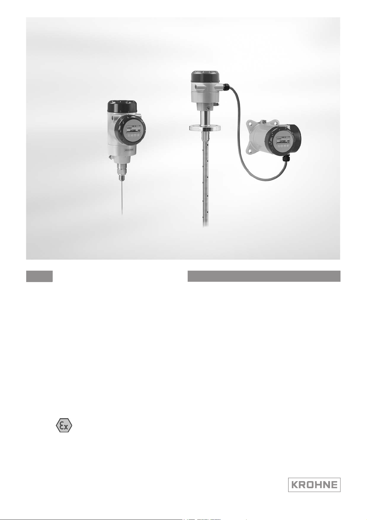
1.2 Device description
OPTIFLEX 2200 C/F
This device is a 2-wire level transmitter that uses TDR (Time Domain Reflectometry) / Guided
Radar technology. It measures the level, distance, volume and mass of liquids, liquid gases,
pastes, powders, slurries and granular products. Measurements are displayed via a DTM (device
type manager) for remote communication or an optional integrated display screen with wizarddriven setup and online help functions.
The level transmitter is approved for use in potentially explosive atmospheres when equipped
with the appropriate options.
1.3 Standards and approvals
DANGER!
In compliance with European Directive 94/9/EC (ATEX 100a), the ATEX version of the device
described in these Supplementary Instructions agrees with European Standards EN 600790:2009, EN 60079-1:2007, EN 60079-11:2012, EN 60079-26:2007, EN 61241-11:2006 and
EN 60079-31:2009. The Ex ia and Ex d ia / Ex ia tb versions are certified for use in hazardous
areas by the DEKRA Certification B.V. under the EC-Type Examination Certificate
DEKRA 11ATEX0166 X. The Ex ic version is certified for use in hazardous areas by the DEKRA
Certification B.V. under the Type Examination Certificate DEKRA 13ATEX0051 X.
WARNING!
Carefully read the ATEX approval certificate. Obey the boundary conditions.
4
www.krohne.com 04/2013 - 4000861602 - AD ATEX OPTIFLEX 2200 R02 en

OPTIFLEX 2200 C/F
1.4 Device categories
1.4.1 Ex ia-approved devices
The Ex ia-approved device is suitable for use in potentially explosive atmospheres of all
flammable substances in Gas Groups IIA, IIB and IIC. It is certified for applications requiring
Category 1/2 G (gases, vapours or mists) and EPL Ga/Gb equipment or 2 G and EPL Gb
equipment when fitted with the appropriate options.
The Ex ia-approved device is suitable for use in potentially explosive atmospheres of all
flammable substances in Dust Groups IIIA, IIIB and IIIC. It is certified for applications requiring
Category 1/2 D (dust) and EPL Da/Db equipment or 2 D and EPL Db equipment when fitted with
the appropriate options.
1.4.2 Ex d ia / Ex ia tb-approved devices
The Ex d ia-approved device is suitable for use in potentially explosive atmospheres of all
flammable substances in Gas Groups IIA, IIB and IIC. It is certified for applications requiring
Category 1/2 G (gases, vapours or mists) and EPL Ga/Gb equipment or 2 G and EPL Gb
equipment when fitted with the appropriate options.
GENERAL SAFETY INFORMATION 1
The Ex ia tb-approved device is suitable for use in potentially explosive atmospheres of all
flammable substances in Dust Group IIIA, IIIB and IIIC. It is certified for applications requiring
Category 1/2 D (dust) and EPL Da/Db equipment or 2 D and EPL Db equipment when fitted with
the appropriate options.
1.4.3 Ex ic-approved devices
The Ex ic-approved device is suitable for use in potentially explosive atmospheres of all
flammable substances in Gas Groups IIA, IIB and IIC. It is certified for applications requiring
Category 3 G (gases, vapours or mists) and EPL Gc equipment when fitted with the appropriate
options.
The Ex ic-approved device is suitable for use in potentially explosive atmospheres of all
flammable substances in Dust Group IIIA, IIIB and IIIC. It is certified for applications requiring
Category 3 D (dust) and EPL Dc equipment when fitted with the appropriate options.
www.krohne.com04/2013 - 4000861602 - AD ATEX OPTIFLEX 2200 R02 en
5
1 GENERAL SAFETY INFORMATION
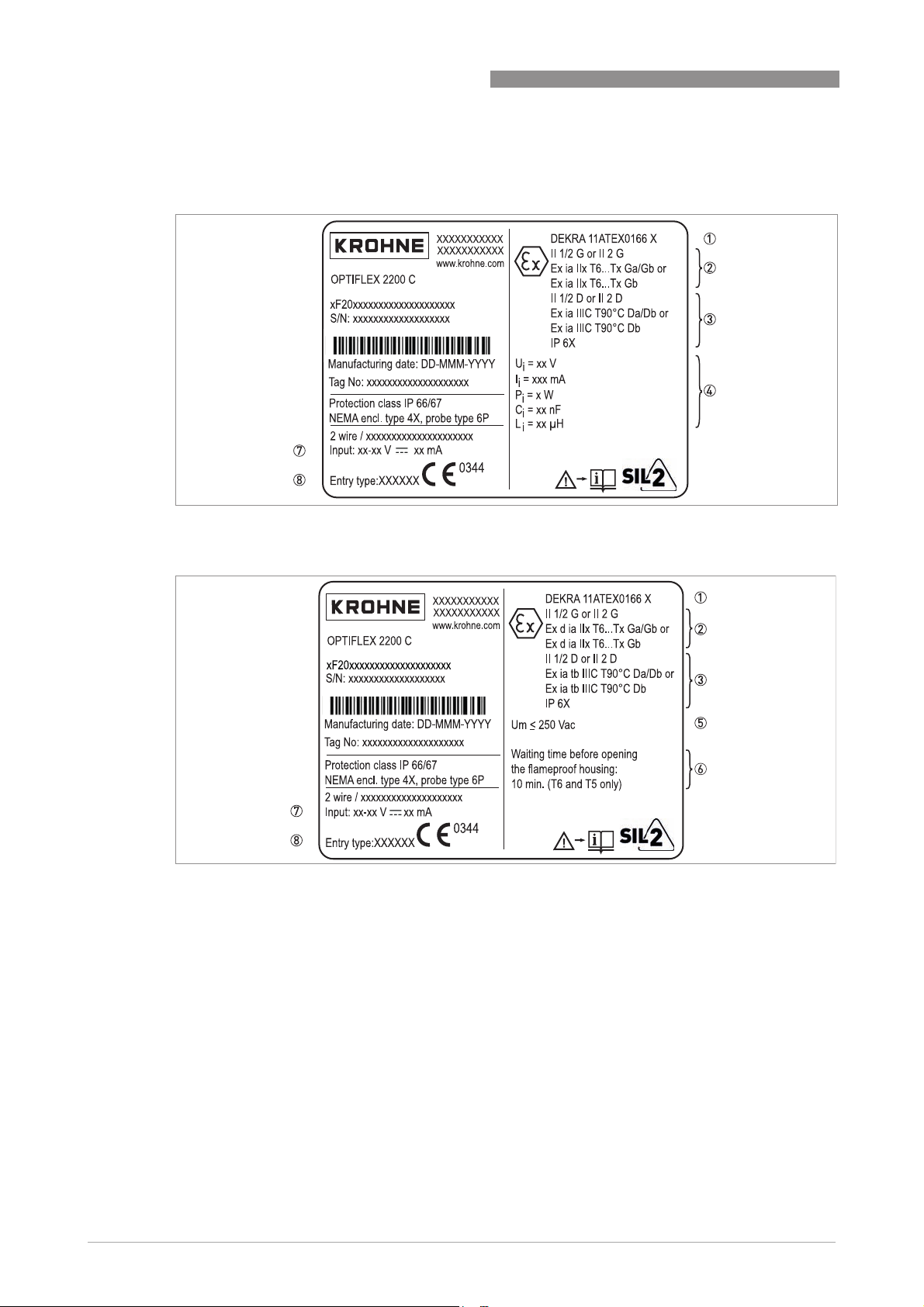
1.5 ATEX nameplates
Compact version
Figure 1-1: Compact version, Ex ia nameplate
OPTIFLEX 2200 C/F
Figure 1-2: Compact version, Ex d ia / Ex ia tb nameplate
1 ATEX certification agency code
2 Equipment approval category (explosive atmosphere - gas), types of device protection including approved Gas Groups
and temperature classes (T6...T3 or T2 - depends on the probe type) and equipment protection level
3 Equipment category (explosive atmosphere - dust), types of device protection including approved Gas Groups, maxi-
mum surface temperature degree of ingress protection (if fitted with the appropriate cable glands) and equipment
protection level
4 4...20 mA passive - HART output option:
4...20 mA passive - HART output option: Intrinsically-safe circuit data
4...20 mA passive - HART output option:4...20 mA passive - HART output option:
Fieldbus (FF or PROFIBUS PA) options:
Fieldbus (FF or PROFIBUS PA) options: Entity or FISCO power supply parameters
Fieldbus (FF or PROFIBUS PA) options:Fieldbus (FF or PROFIBUS PA) options:
5 4...20 mA passive - HART output option:
4...20 mA passive - HART output option: Maximum voltage in accordance with EN 60079-0. Refer to 7 for the input
4...20 mA passive - HART output option:4...20 mA passive - HART output option:
voltage range.
6 4...20 mA passive - HART output option:
4...20 mA passive - HART output option: Minimum waiting time after power-off before it is safe to open the terminal
4...20 mA passive - HART output option:4...20 mA passive - HART output option:
compartment
Fieldbus (FF or PROFIBUS PA) options:
Fieldbus (FF or PROFIBUS PA) options: Entity or FISCO power supply parameters
Fieldbus (FF or PROFIBUS PA) options:Fieldbus (FF or PROFIBUS PA) options:
7 Input voltage range and maximum current (4...20 mA passive - HART) / basic current (FF or PROFIBUS PA)
8 Cable entry type and size (M20×1.5 or ½ NPT)
6
www.krohne.com 04/2013 - 4000861602 - AD ATEX OPTIFLEX 2200 R02 en
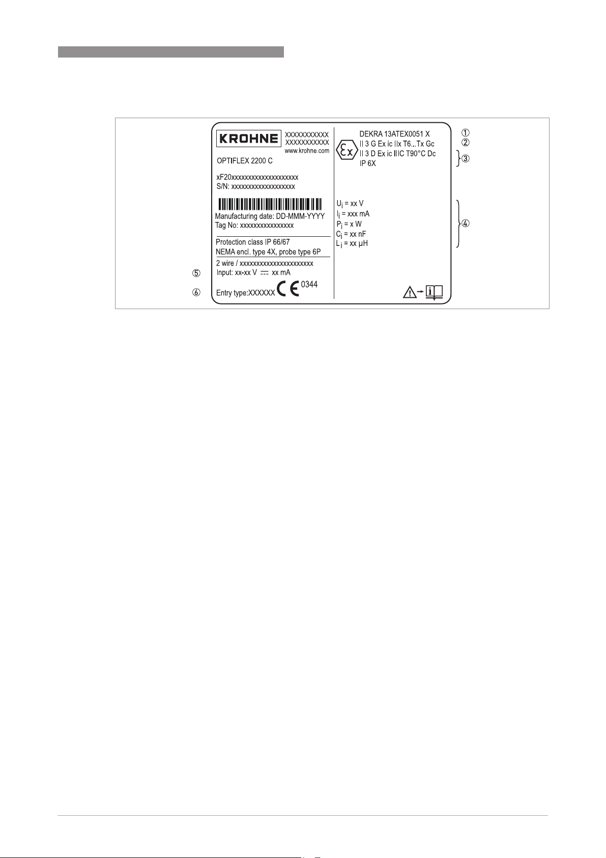
OPTIFLEX 2200 C/F
Figure 1-3: Compact version, Ex ic nameplate
1 ATEX certification agency code
2 Equipment approval category (explosive atmosphere - gas), types of device protection including approved Gas Groups
and temperature classes (T6...T3 or T2 - depends on the probe type) and equipment protection level
3 Equipment category (explosive atmosphere - dust), types of device protection including approved Gas Groups, maxi-
mum surface temperature degree of ingress protection (if fitted with the appropriate cable glands) and equipment
protection level
4 4...20 mA passive - HART output option:
4...20 mA passive - HART output option: Intrinsically-safe circuit data
4...20 mA passive - HART output option:4...20 mA passive - HART output option:
Fieldbus (FF or PROFIBUS PA) options:
Fieldbus (FF or PROFIBUS PA) options: Entity or FISCO power supply parameters
Fieldbus (FF or PROFIBUS PA) options:Fieldbus (FF or PROFIBUS PA) options:
5 Input voltage range and maximum current (4...20 mA passive - HART) / basic current (FF or PROFIBUS PA)
6 Cable entry type and size (M20×1.5 or ½ NPT)
GENERAL SAFETY INFORMATION 1
www.krohne.com04/2013 - 4000861602 - AD ATEX OPTIFLEX 2200 R02 en
7
1 GENERAL SAFETY INFORMATION
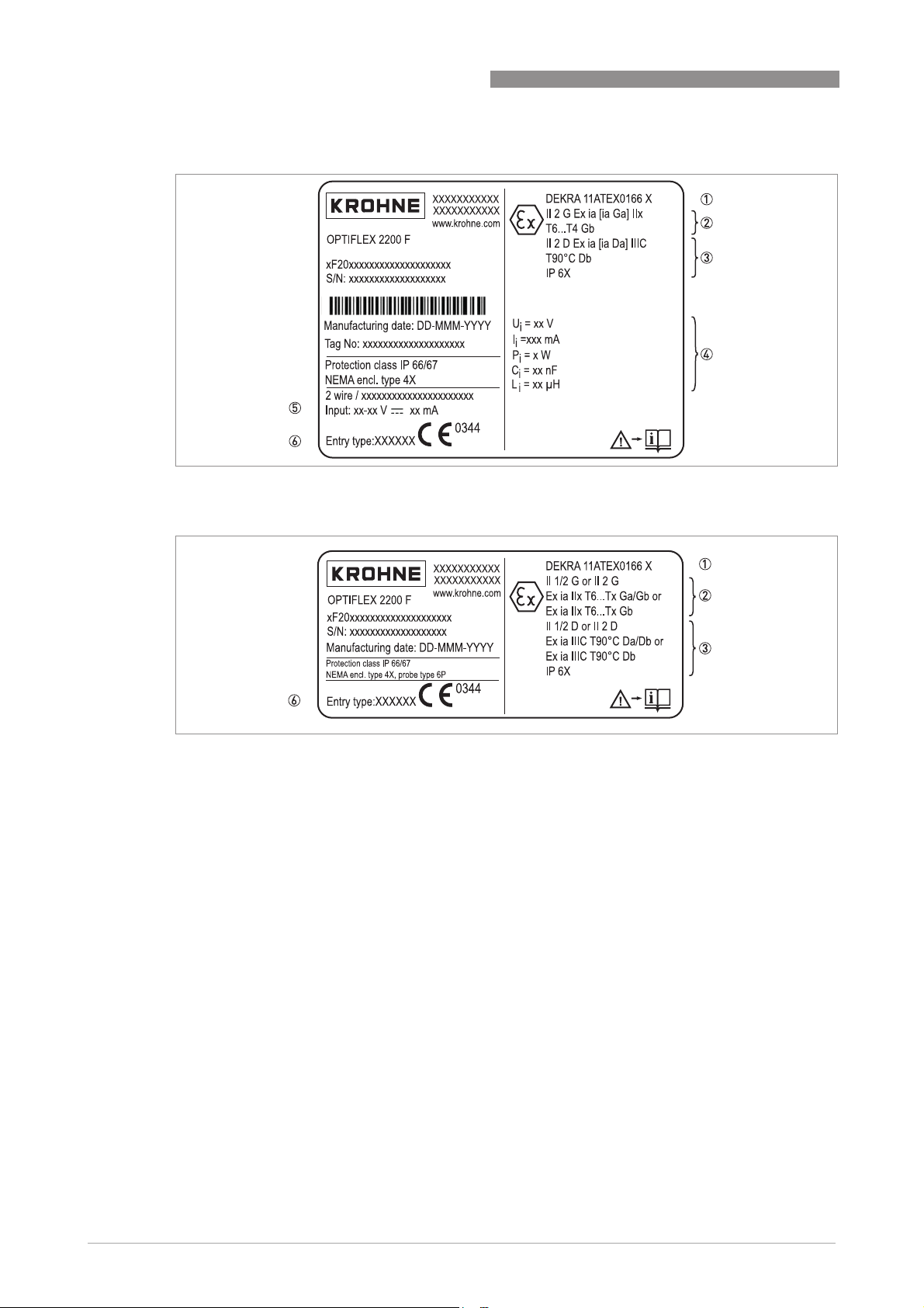
Remote (Field) version
Figure 1-4: Remote version, Ex ia nameplate on the converter housing
OPTIFLEX 2200 C/F
Figure 1-5: Remote version, Ex ia nameplate on the probe housing
1 ATEX certification agency code
2 Equipment approval category (explosive atmosphere - gas), types of device protection including approved Gas Groups,
temperature classes (T6...T3 or T2 - depends on the probe type) and equipment protection level
3 Equipment category (explosive atmosphere - dust), types of device protection for explosive atmospheres with dust,
zones, maximum surface temperature, equipment protection level and degree of ingress protection (if fitted with the
appropriate cable glands)
4 4...20 mA passive - HART output option:
4...20 mA passive - HART output option: Intrinsically-safe circuit data for the device
4...20 mA passive - HART output option:4...20 mA passive - HART output option:
Fieldbus (FF or PROFIBUS PA) options:
Fieldbus (FF or PROFIBUS PA) options: Entity or FISCO power supply parameters
Fieldbus (FF or PROFIBUS PA) options:Fieldbus (FF or PROFIBUS PA) options:
5 Input voltage range and maximum current (4...20 mA passive - HART) / basic current (FF or PROFIBUS PA)
6 Cable entry type and size (M20×1.5 or ½NPT)
8
www.krohne.com 04/2013 - 4000861602 - AD ATEX OPTIFLEX 2200 R02 en
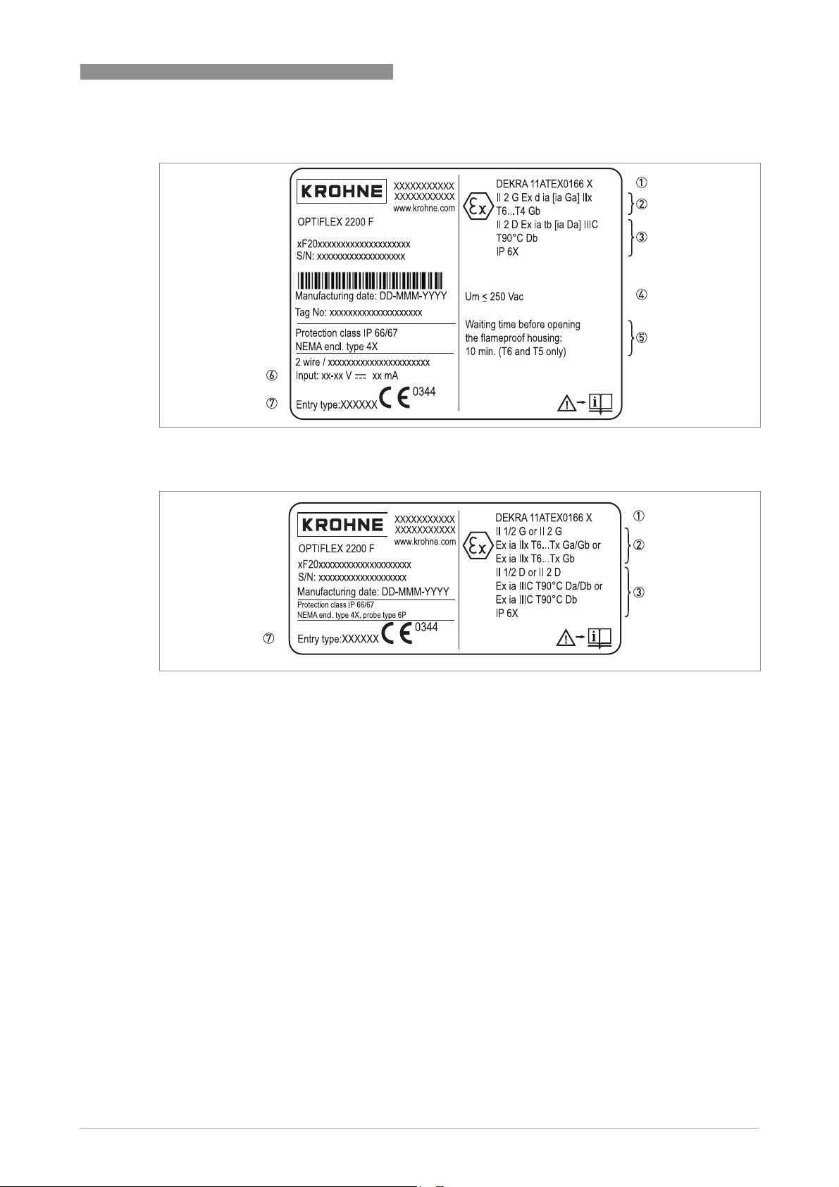
OPTIFLEX 2200 C/F
Figure 1-6: Remote version, Ex d / Ex ia tb nameplate on the converter housing
GENERAL SAFETY INFORMATION 1
Figure 1-7: Remote version, Ex ia nameplate on the probe housing
1 ATEX certification agency code
2 Equipment approval category (explosive atmosphere - gas), types of device protection including approved Gas Groups,
temperature classes (T6...T3 or T2 - depends on the probe type) and equipment protection level
3 Equipment category (explosive atmosphere - dust), types of device protection for explosive atmospheres with dust,
zones, maximum surface temperature and degree of ingress protection (if fitted with the appropriate cable glands)
4 4...20 mA passive - HART output option:
4...20 mA passive - HART output option: Maximum voltage in accordance with EN 60079-0. Refer to 7 for the input
4...20 mA passive - HART output option:4...20 mA passive - HART output option:
voltage range.
5 4...20 mA passive - HART output option:
4...20 mA passive - HART output option: Minimum waiting time after power-off before it is safe to open the terminal
4...20 mA passive - HART output option:4...20 mA passive - HART output option:
compartment
Fieldbus (FF or PROFIBUS PA) options:
Fieldbus (FF or PROFIBUS PA) options: Entity or FISCO power supply parameters
Fieldbus (FF or PROFIBUS PA) options:Fieldbus (FF or PROFIBUS PA) options:
6 Input voltage range and maximum current (4...20 mA passive - HART) / basic current (FF or PROFIBUS PA)
7 Cable entry type and size (M20×1.5 or ½ NPT)
www.krohne.com04/2013 - 4000861602 - AD ATEX OPTIFLEX 2200 R02 en
9
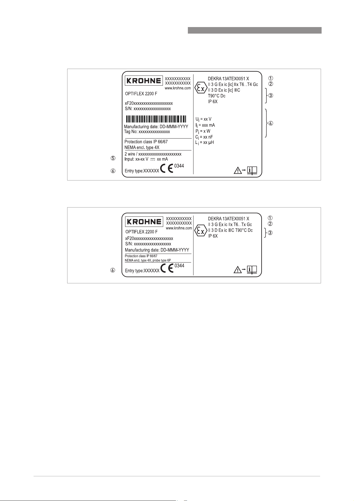
1 GENERAL SAFETY INFORMATION
Figure 1-8: Remote version, Ex ic nameplate on the converter housing
OPTIFLEX 2200 C/F
Figure 1-9: Remote version, Ex ic nameplate on the probe housing
1 ATEX certification agency code
2 Equipment approval category (explosive atmosphere - gas), types of device protection including approved Gas Groups,
temperature classes (T6...T3 or T2 - depends on the probe type) and equipment protection level
3 Equipment category (explosive atmosphere - dust), types of device protection for explosive atmospheres with dust,
zones, maximum surface temperature and degree of ingress protection (if fitted with the appropriate cable glands)
4 4...20 mA passive - HART output option:
4...20 mA passive - HART output option: Intrinsically-safe circuit data
4...20 mA passive - HART output option:4...20 mA passive - HART output option:
Fieldbus (FF or PROFIBUS PA) options:
Fieldbus (FF or PROFIBUS PA) options: Entity or FISCO power supply parameters
Fieldbus (FF or PROFIBUS PA) options:Fieldbus (FF or PROFIBUS PA) options:
5 Input voltage range and maximum current (4...20 mA passive - HART) / basic current (FF or PROFIBUS PA)
6 Cable entry type and size (M20×1.5 or ½ NPT)
10
www.krohne.com 04/2013 - 4000861602 - AD ATEX OPTIFLEX 2200 R02 en
 Loading...