

KROHNE OPTIFLEX 1300 C Specifications
Technical Datasheet
Technical Datasheet
OPTIFLEX 1300 C
OPTIFLEX 1300 C
OPTIFLEX 1300 COPTIFLEX 1300 C
Technical DatasheetTechnical Datasheet
Guided Radar (TDR) Level Transmitter for heavy-duty
and interface applications
•
Universal device that can measure level of liquids, pastes, granulates, powders,
and liquid interface
•
Easy to install: on-site calibration is not needed
•
Operates up to 300 bar / 4350 psi
© KROHNE 07/2015 - 4000112208 - TD OPTIFLEX 1300 R13 en

CONTENTS
OPTIFLEX 1300 C
1 Product features 3
1.1 The superior TDR solution ............................................................................................... 3
1.2 Applications ...................................................................................................................... 5
1.3 Application table for probe selection ............................................................................... 8
1.4 Measuring principle.......................................................................................................... 9
2 Technical data 12
2.1 Technical data................................................................................................................. 12
2.2 Pressure/temperature table for probe selection .......................................................... 18
2.3 Guidelines for maximum operating pressure (CRN certification) ................................ 19
2.4 Measurement limits ....................................................................................................... 23
2.5 Dimensions and weights ................................................................................................ 26
3 Installation 40
3.1 Intended use ................................................................................................................... 40
3.2 Pre-installation requirements ....................................................................................... 40
3.3 How to prepare the tank before you install the device.................................................. 41
3.3.1 General information for nozzles........................................................................................... 41
3.3.2 Installation requirements for concrete roofs....................................................................... 43
3.3.3 Recommendations for pits and tanks made of non-conductive materials.......................... 43
3.4 Installation recommendations for liquids...................................................................... 44
3.4.1 General requirements .......................................................................................................... 44
3.4.2 Standpipes............................................................................................................................. 45
3.5 Installation recommendations for solids....................................................................... 49
3.5.1 Nozzles on conical silos........................................................................................................ 49
3.5.2 Traction loads on the probe.................................................................................................. 50
4 Electrical connections 51
4.1 Electrical installation: outputs 1 and 2 .......................................................................... 51
4.1.1 Non-Ex devices ..................................................................................................................... 51
4.1.2 Devices for hazardous locations........................................................................................... 52
4.2 Protection category ........................................................................................................52
4.3 Networks ........................................................................................................................ 53
4.3.1 General information.............................................................................................................. 53
4.3.2 Point-to-point networks ....................................................................................................... 53
4.3.3 Multi-drop networks ............................................................................................................. 54
5 Order information 55
5.1 Order code ...................................................................................................................... 55
6 Notes 66
2
www.krohne.com 07/2015 - 4000112208 - TD OPTIFLEX 1300 R13 en
OPTIFLEX 1300 C
1.1 The superior TDR solution
This device is a Guided Radar (TDR) Level Transmitter for measuring distance, level, interface,
level and interface, volume and mass. It has higher signal dynamics and a sharper pulse than
conventional TDR devices and therefore better reproducibility and accuracy. A variant with a
remote converter can be mounted up to 14.5 m / 47.6 ft from the probe. The device can operate
at very low and very high process temperatures as long as the process connection temperature
limits are observed.
PRODUCT FEATURES
1
1 Touch screen with 4-button operation
2 2-wire level meter
3 Converter is rotatable and removable under process conditions
4 5 different types of probes suitable for a wide range of media
5 Optional ESD protection (30 kV) or Metaglas® dual process sealing system for dangerous products
6 Same converter for Ex and non-Ex
7 Large graphical display
www.krohne.com07/2015 - 4000112208 - TD OPTIFLEX 1300 R13 en
3

1
PRODUCT FEATURES
Highlights
• Displays level and interface
• PACTware and DTMs included as standard
• Optional second current output – used for displaying interface measurements, for example
• High-pressure and high-temperature versions
• Optimal process safety (with Metaglas® dual process sealing system for dangerous products)
• Display in 9 languages: even in Chinese, Japanese and Russian
• Available in stainless steel and HASTELLOY® C-22®. Other materials are available on
request: monel, tantalum, titanium, duplex etc.
• Angled single cable and rod probes are available on request for installation in tanks which
contain obstructions
Industries
• Chemicals & Petrochemicals
• Oil & Gas
• Minerals & Mining
• Wastewater
• Pulp & Paper
• Food & Beverages
• Pharmaceutical
• Energy
OPTIFLEX 1300 C
Applications
• Blending tanks
• Distillation tanks
• Process tanks
• Separator
• Solid silos (inventory)
• Storage tanks
4
www.krohne.com 07/2015 - 4000112208 - TD OPTIFLEX 1300 R13 en
OPTIFLEX 1300 C
1.2 Applications
1. Level measurement of liquids
PRODUCT FEATURES
The level transmitter can measure the level of a
wide range of liquid products on a large variety of
installations within the stated pressure and
temperature range, including LPG and LNG. It does
not require calibration or commissioning when
installed. A Metaglas® option is also available for
dangerous products and ensures that no leakage is
possible.
A number of probe end attachments are available.
For example, the user can fix the end of cable probes
to heating coils: the heat prevents deposits building
up on the probe.
1
2. Interface measurement of liquids
The level transmitter can measure interface with or
without an air gap. It can also measure level and
interface simultaneously. It has an optional second
analogue output.
The coaxial probe of the level transmitter has a top
dead zone of only 35 mm / 1.4¨: this makes it ideal
for tracking full tank or ballast interface.
www.krohne.com07/2015 - 4000112208 - TD OPTIFLEX 1300 R13 en
5
1
PRODUCT FEATURES
3. Level measurement of solids
4. Measurement of liquids in a bypass chamber
OPTIFLEX 1300 C
The level transmitter has a strengthened Ø8 mm /
0.3¨ single cable probe for measuring powders and
granulates in silos up to 35 m / 115 ft high.
The Ø4 mm / 0.15¨ single cable probe is used for
small silos. An ESD protection (30 kV) option is also
available.
If a product has a very low dielectric constant
(ε
<1.6), the level transmitter automatically
r
switches to TBF (Tank Bottom Following) mode and
keeps operating.
The level transmitter can measure accurately in
agitated conditions and in the presence of foam. If
the tank is full of obstructions such as agitators and
reinforcements, we recommend installing the level
transmitter in a bypass chamber. This solution is
available from KROHNE under the name BM 26 F.
Please refer to the BM 26 F documentation for
further information.
6
www.krohne.com 07/2015 - 4000112208 - TD OPTIFLEX 1300 R13 en
OPTIFLEX 1300 C
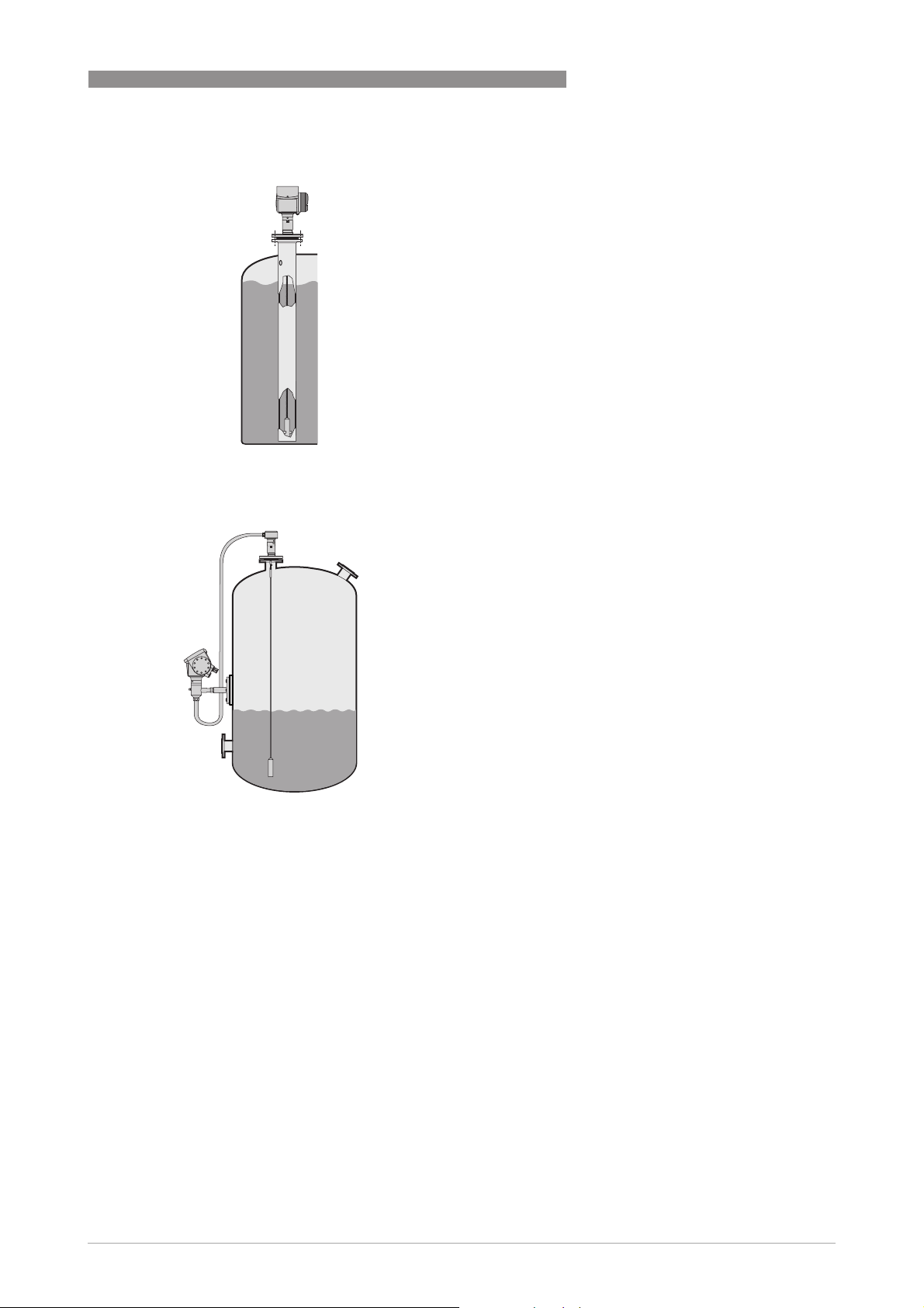
5. Measurement of liquids in a still well
6. Remote display on high or inaccessible tanks
PRODUCT FEATURES
You can also install the level transmitter in a still
well if there are vortices, agitators or other
obstructions in the tank. It is also suitable for tanks
with floating roofs. The level transmitter's setup
wizard allows you to quickly configure your device to
suit specific types of installations and get the best
possible performance from it.
1
If it is difficult or impossible to read the level
transmitter's integrated display at the top of the
tank, we recommend the remote display variant. It is
provided with a cable up to 14.5 m / 47.6 ft long and a
bracket for mounting in an accessible position.
If there is vibration in the installation, we also
recommend that you attach the remote converter to
a wall or another safe object that is not attached to
the installation.
www.krohne.com07/2015 - 4000112208 - TD OPTIFLEX 1300 R13 en
7
1
PRODUCT FEATURES
1.3 Application table for probe selection
Maximum probe length, L
4m/ 13ft
6m/ 20ft
8m/ 26ft
35 m / 115 ft
Double rod
OPTIFLEX 1300 C
Single rod
Single rod (segmented)
Coaxial
Coaxial (segmented)
Double cable
Single cable Ø8 mm / 0.32¨
Single cable Ø4 mm / 0.16¨
Single cable Ø2 mm / 0.08¨
Liquids
Liquid application
LPG, LNG
Highly viscous liquids
Highly crystallising liquids
Highly corrosive liquids
Foam
Agitated liquids
High-pressure applications
High-temperature applications
Spray in tank
Storage tanks
Installation in bypass chamber
Small diameter nozzles
Long nozzles
Stilling wells
Interface measurement
Solids
Powders
Granules, <5 mm / 0.1¨
1 1
2 2 2 2 2
3 3 3 3 3 3 3 4
5
1 1 1 1
6 6
7
7
J standard J optional U on request
1 Install the device in a stilling well or a bypass chamber
2 Use this probe with an anchor fitting. For more data, refer to the handbook.
3 Max. pressure is 100 bar / 1450 psig. Refer to the pressure-temperature table for probe selection.
4 Optional. Max. pressure is 300 bar / 4350 psig. Refer to the pressure-temperature table for probe selection.
5 Optional. Max. temperature is 300°C/ 570°F. Refer to the pressure-temperature table for probe selection.
6 Max. length is 20 m / 65.5 ft, more on request
7 Max. length is 10 m / 33 ft, more on request
8
www.krohne.com 07/2015 - 4000112208 - TD OPTIFLEX 1300 R13 en

OPTIFLEX 1300 C
1.4 Measuring principle
This Guided Radar (TDR) level meter has been developed from a proven technology called Time
Domain Reflectometry (TDR).
The device transmits low-intensity electromagnetic pulses of approximately half a nanosecond
width along a rigid or flexible conductor. These pulses move at the speed of light. When the
pulses reach the surface of the product to be measured, the pulses are reflected with an
intensity that depends on the dielectric constant, ε
dielectric constant and reflects the pulse back to the meter converter at 80% of its original
intensity).
The device measures the time from when the pulse is emitted to when it is received: half of this
time is equivalent to the distance from the reference point of the device (the flange facing) to the
surface of the product. The time value is converted into an output current of 4...20 mA and/or a
digital signal.
Dust, foam, vapor, agitated surfaces, boiling surfaces, changes in pressure, changes in
temperature and changes in density do not have an effect on device performance.
PRODUCT FEATURES
, of the product (for example, water has a high
r
1
The illustration that follows shows a snapshot of what a user would see on an oscilloscope, if the
level of one product is measured.
www.krohne.com07/2015 - 4000112208 - TD OPTIFLEX 1300 R13 en
9
1
PRODUCT FEATURES
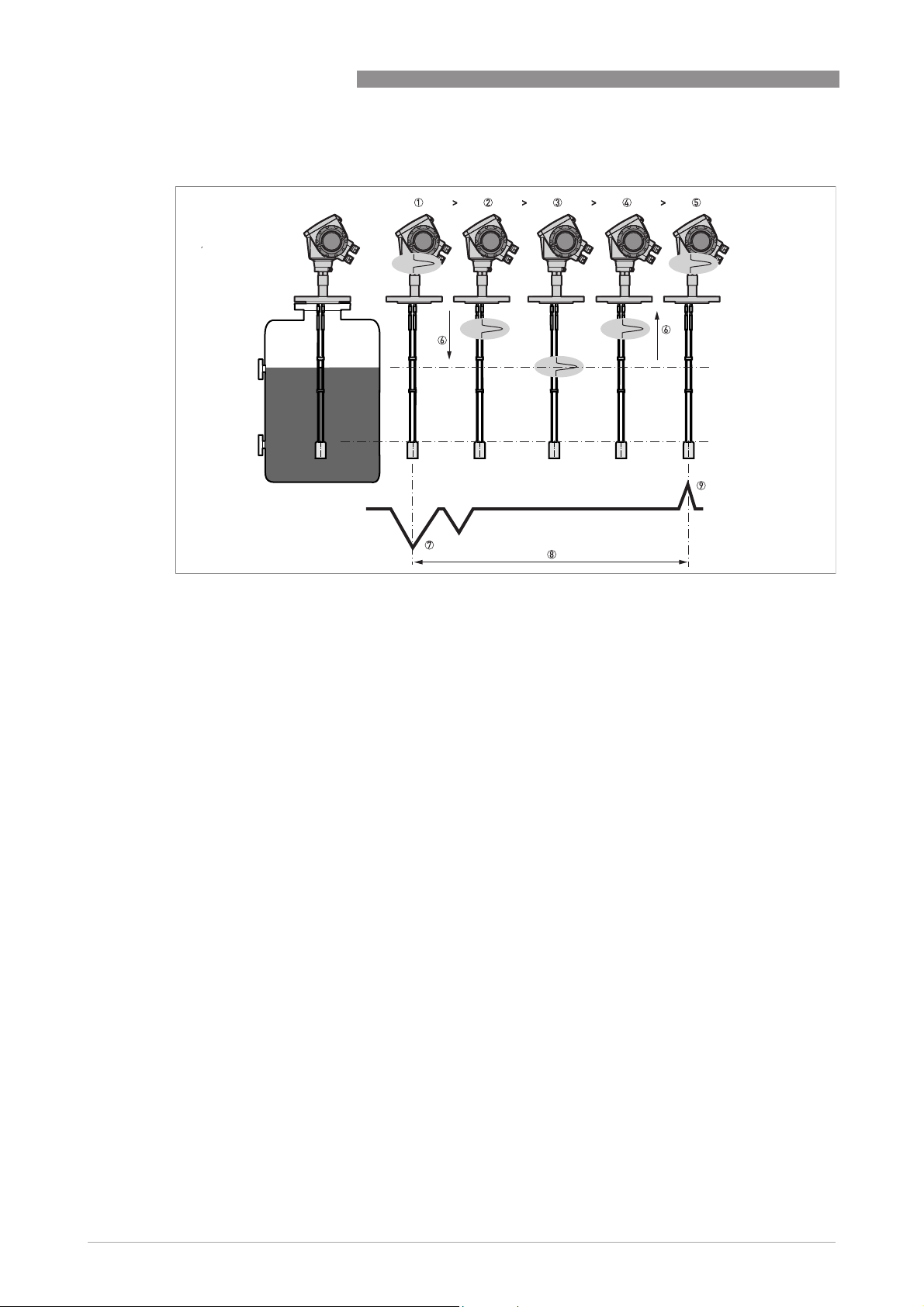
Level measurement principle (direct mode)
OPTIFLEX 1300 C
Figure 1-1: Level measurement principle
1 Time 0: The electromagnetic (EM) pulse is transmitted by the converter
2 Time 1: The pulse goes down the probe at the speed of light in air, V1
3 Time 2: The pulse is reflected
4 Time 3: The pulse goes up the probe at speed, V1
5 Time 4: The converter receives the pulse and records the signal
6 The EM pulse moves at speed, V1
7 Transmitted EM pulse
8 Half of this time is equivalent to the distance from the reference point of the device (the flange facing) to the surface
of the product
9 Received EM pulse
The illustration that follows shows a snapshot of what a user would see on an oscilloscope, if the
level and/or interface of products are measured.
Interface measurement:
Interface measurement: The dielectric constant of the top liquid must be less than the dielectric
Interface measurement:Interface measurement:
constant of the bottom liquid. If not, or if there is too small a difference, the device may not
measure correctly.
10
www.krohne.com 07/2015 - 4000112208 - TD OPTIFLEX 1300 R13 en
OPTIFLEX 1300 C
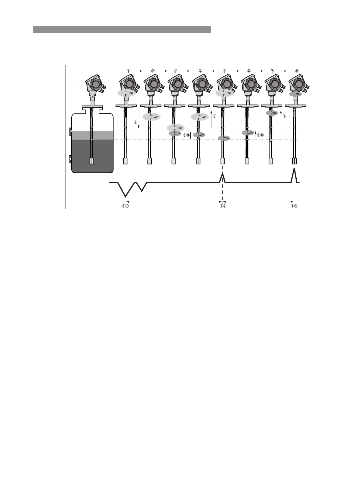
Level and interface measurement principle (direct measurement)
PRODUCT FEATURES
1
Figure 1-2: Level and interface measurement principle (2 liquids in the tank)
1 Time 0: The electromagnetic (EM) pulse is transmitted by the converter
2 Time 1: The pulse goes down the probe at the speed of light in air, V1
3 Time 2: Part of the pulse is reflected at the surface of the top liquid, the remaining pulse goes down the probe
4 Time 3: Part of the pulse goes up the probe at speed, V1. The remaining pulse goes down the probe at the speed of
light in the top product, V2
5 Time 4: The converter receives part of the pulse and records the signal. The remaining pulse is reflected at the inter-
face of the 2 liquids
6 Time 5: The remaining pulse is goes up the probe at speed, V2
7 Time 6: The remaining pulse goes up the probe at speed, V1
8 Time 7: The converter receives the remaining pulse and records the signal
9 The EM pulse moves at speed, V1
10 The EM pulse moves at speed, V2
11 Transmitted EM pulse
12 Received EM pulse (distance to the top liquid)
13 Received EM pulse (distance to the interface of 2 liquids)
If products have a very low dielectric constant (εr<1.6), only a small part of the EM pulse is
reflected at the surface of the product. Most of the pulse is reflected at the probe end. TBF (tank
bottom following) mode is used to measure the distance to the product surface.
TBF mode (indirect measurement) compares:
• The time for the pulse to go to the probe end and go back to the converter when the tank is
empty.
• The time for the pulse to go to the probe end and go back to the converter when the tank is
full or partially filled.
The level of the product in the tank can be calculated from the time difference.
www.krohne.com07/2015 - 4000112208 - TD OPTIFLEX 1300 R13 en
11

2
TECHNICAL DATA
OPTIFLEX 1300 C
2.1 Technical data
•
The following data is provided for general applications. If you require data that is more
relevant to your specific application, please contact us or your local sales office.
•
Additional information (certificates, special tools, software,...) and complete product
documentation can be downloaded free of charge from the website (Downloadcenter).
Measuring system
Measuring principle 2-wire loop-powered level transmitter; Time Domain Reflectometry (TDR)
Application range Level measurement of liquids, pastes, slurries, powders and granulates
Primary measured value Time between the emitted and received signal
Secondary measured value Distance, level, volume, mass and/or interface
Design
Construction The measurement system consists of a measuring sensor (probe) and a signal
Options Integrated LCD display with sun cover (-20…+60°C/ -4…+140°F);
Accessories Weather protection
Max. measuring range Double rod Ø8 mm / 0.32¨: 4 m / 13 ft
Tolerance, probe length ±0.5%
Dead zone This depends on the type of probe. For more data, refer to
converter which is available in a compact or remote version
if the ambient temperature is not in these limits, the display switches off
2nd current output
ESD protection (max. 30 kV)
Metaglas® (dual process sealing system for dangerous products (ammonia,
chlorine, ...))
Remote housing connected to the probe via a flexible conduit
Standard lengths: 2 m / 6.6 ft, 4.5 m / 14.8 ft, 9.5 m / 31.2 ft and 14.5 m / 47.6 ft
Probe end types (not for rod and coaxial probes)
Probe end types (not for rod and coaxial probes)
Probe end types (not for rod and coaxial probes)Probe end types (not for rod and coaxial probes)
Standard: Counterweights (refer to counterweight dimensions in "Technical data:
Dimensions and weights")
Options: Turnbuckle, chuck, threaded end, crimped end, open end
Discs (low-pressure flanges) with bolt hole dimensions and positions that agree
with DN80...200 in PN06 or 3¨...8¨ in 150 lb for devices with the G 1½ threaded
connection. Max. pressure: 1 barg / 14.5 psig at +20°C / +68°F.
Single rod Ø8 mm / 0.32¨: 4 m / 13 ft
Single rod Ø8 mm / 0.32¨ (segmented): 6 m / 20 ft
Coaxial Ø22 mm / 0.87¨: 6 m / 20 ft
Coaxial Ø22 mm / 0.87¨ (segmented): 6 m / 20 ft
Double cable Ø4 mm / 0.16¨: 8 m / 26 ft
Single cable Ø2 mm / 0.08¨: 35 m / 115 ft (for liquids only)
Single cable Ø4 mm / 0.16¨: 35 m / 115 ft (an angled probe is available on request
for installations with very low ceilings or objects in the tank that prevent installation
on top of the tank)
Single cable Ø8 mm / 0.32¨: 35 m / 115 ft (for solids only)
1
Measurement limits
page 23.
on
12
www.krohne.com 07/2015 - 4000112208 - TD OPTIFLEX 1300 R13 en

OPTIFLEX 1300 C
Display and User interface
Display and User interface
Display and User interfaceDisplay and User interface
Display LCD display
9 lines, 160×160 pixels in 8-step grayscale with 4-button keypad
Interface languages English, German, French, Italian, Spanish, Portuguese, Japanese, Simplified
Chinese and Russian
TECHNICAL DATA
Accuracy
Resolution 1mm/ 0.04¨
Repeatability ±1mm/ ±0.04¨
Accuracy (in direct mode) Liquids:
Accuracy (in TBF mode) ±20 mm / ±0.8¨ (εr constant)
Minimum layer (interface) 50 mm / 2¨
Reference conditions acc. to EN 60770
Reference conditions acc. to EN 60770
Reference conditions acc. to EN 60770Reference conditions acc. to EN 60770
Temperature +20°C ±5°C / +68°F ±10°F
Pressure 1013 mbara ±20 mbar / 14.69 psia ±0.29 psi
Relative air humidity 60% ±15%
Liquids:
Liquids:Liquids:
±3mm/ ±0.12¨, when distance <10m/ 33ft;
±0.03% of measured distance, when distance > 10 m / 33 ft
Powders:
Powders:
Powders:Powders:
±20 mm / ±0.8¨
Interface:
Interface:
Interface:Interface:
±10 mm / ±0.4¨ (εr constant)
2
Operating conditions
Temperature
Temperature
TemperatureTemperature
Ambient temperature -40…+80°C/ -40…+176°F
Storage temperature -40…+85°C/ -40…+185°F
Process connection temperature Standard
Pressure
Pressure
PressurePressure
Operating pressure Single cable Ø8 mm / 0.32
Ex: see supplementary operating instructions or approval certificates
Standard
StandardStandard
-50…+200°C/ -58…+392°F (according to the temperature limits of the gasket
material. Refer to "Material" in this table.)
Ex: see supplementary operating instructions or approval certificates
High-Temperature (HT) and High-Temperature / High-Pressure (HT/HP) versions
High-Temperature (HT) and High-Temperature / High-Pressure (HT/HP) versions
High-Temperature (HT) and High-Temperature / High-Pressure (HT/HP) versions High-Temperature (HT) and High-Temperature / High-Pressure (HT/HP) versions
with FKM/FPM and Kalrez
with FKM/FPM and Kalrez® 6375 gaskets
with FKM/FPM and Kalrezwith FKM/FPM and Kalrez
+300°C / +572°F (single cable Ø2 mm / 0.08¨ probe only)
Ex: see supplementary operating instructions or approval certificates
HT and HT/HP versions with EPDM gaskets
HT and HT/HP versions with EPDM gaskets
HT and HT/HP versions with EPDM gasketsHT and HT/HP versions with EPDM gaskets
+250°C / +482°F (single cable Ø2 mm / 0.08¨ probe only)
Ex: see supplementary operating instructions or approval certificates
Single cable Ø8 mm / 0.32¨ probe
Single cable Ø8 mm / 0.32Single cable Ø8 mm / 0.32
-1…40 barg / -14.5…580 psig
subject to process connection temperature and probe type used
High-Pressure (HP) version
High-Pressure (HP) version
High-Pressure (HP) versionHigh-Pressure (HP) version
max. 300 barg / 4350 psig (single cable Ø2 mm / 0.08¨ probe only)
subject to process connection temperature and probe type used
All other probe types
All other probe types
All other probe typesAll other probe types
-1…100 barg / -14.5…1450 psig
subject to process connection temperature and probe type used
6375 gaskets
6375 gaskets6375 gaskets
probe
probe probe
2
2
2
2
2
2
www.krohne.com07/2015 - 4000112208 - TD OPTIFLEX 1300 R13 en
13

2
TECHNICAL DATA
Other conditions
Other conditions
Other conditionsOther conditions
Dielectric constant (εr) Level in direct mode:
Vibration resistance IEC 60068-2-6 and EN 50178 (10...57 Hz: 0.075 mm / 57...150 Hz:1g)
Protection category IP 66/67 equivalent to NEMA 4X (housing) and 6P (probe)
Level in direct mode:
Level in direct mode:Level in direct mode:
≥1.4 for coaxial probe; ≥1.6 for single and double probes
Interface in direct mode:
Interface in direct mode:
Interface in direct mode:Interface in direct mode:
εr(interface) >> εr(level)²
Level in TBF mode:
Level in TBF mode:
Level in TBF mode:Level in TBF mode:
≥1.1
OPTIFLEX 1300 C
Installation conditions
Process connection size Refer to "Installation: How to prepare the tank before you install the device" and
Process connection position Make sure that there are not any obstructions directly below the process
Dimensions and weights Refer to "Technical data: Dimensions and weights"
"Technical data: Measurement limits"
connection for the device.
Material
Housing Standard: Polyester-coated aluminium
Option: Stainless steel (1.4404 / 316L)
Single rod (single-piece) Standard: Stainless steel (1.4404 / 316L)
Option: Stainless steel (1.4404 / 316L) in a PVDF protective sheath, HASTELLOY®
C-22® (2.4602)
On request: Stainless steel (1.4404 / 316L) in a PVC or PP protective sheath
On request: Monel; Tantalum; Titanium; Duplex
Single rod (segmented) Standard: Stainless steel (1.4404 / 316L)
Double rod Standard: Stainless steel (1.4404 / 316L)
Option: HASTELLOY® C-22® (2.4602)
On request: Monel; Tantalum; Titanium; Duplex
Coaxial (single-piece) Standard: Stainless steel (1.4404 / 316L)
Option: HASTELLOY® C-22® (2.4602)
Coaxial (segmented) Standard: Stainless steel (1.4404 / 316L)
Single cable Standard: Stainless steel (1.4401 / 316)
Option: HASTELLOY® C-22® (2.4602)
– only for the Ø2 mm / 0.08¨ single cable probe
On request: FEP-coated stainless steel (-20...+150°C / -4...+302°F)
– only for the Ø4 mm / 0.16¨ single cable probe
Double cable Stainless steel (1.4401 / 316)
Process fitting Standard: Stainless steel (1.4404 / 316L)
Option: HASTELLOY® C-22® (2.4602)
On request: Monel; Tantalum; Titanium; Duplex
Gaskets FKM/FPM (-40…+200°C/ -40…+392°F); Kalrez® 6375 (-20…+200°C/ -4…+392°F);
Weather protection (Option) Stainless steel (1.4301 / 304)
Protective sheath
(On request for single rod only)
Conduit for remote housing
(Option)
EPDM (-50...+150°C / -58...+302°F) – all probes except single cable Ø8 mm / 0.32¨
PP (-40…+90°C/ -40…+194°F); PVC (-15…+80°C/ +5…+176°F);
PVDF (-40…+150°C/ -40…+302°F)
Zinc-coated steel in a PVC sheath (-40...+105°C / -40...+221°F)
4
3
5
14
www.krohne.com 07/2015 - 4000112208 - TD OPTIFLEX 1300 R13 en

OPTIFLEX 1300 C
TECHNICAL DATA
Process connections
Thread
Thread
ThreadThread
Single cable Ø2 mm / 0.08¨ G ½ (ISO 228); ½ NPT (ASME B1.20.1); ½ NPTF (ASME B1.20.3 – for the HT/HP
Single cable Ø8 mm / 0.32¨
Double cable Ø4 mm / 0.16¨
Double rod Ø8 mm / 0.32¨
All other probes G ¾…1½ (ISO 228); ¾…1½ NPT (ASME B1.20.1)
Flange versions for double rod and double cable probes
Flange versions for double rod and double cable probes
Flange versions for double rod and double cable probesFlange versions for double rod and double cable probes
EN 1092-1 DN50...80 in PN40 (Type B1), DN100…200 in PN16 or PN40 (Type B1), DN50...150 in
ASME B16.5 2¨…8¨ in 150 lb, 2¨...6¨ in 300 lb RF, 2¨...4¨ in 600 lb RF; 3¨...4¨ 900 lb RF, 2¨ in 900 lb
JIS B2220 50…100A in 10K; others on request
Flange versions for single cable Ø8 mm / 0.32
Flange versions for single cable Ø8 mm / 0.32¨ cable probes
Flange versions for single cable Ø8 mm / 0.32Flange versions for single cable Ø8 mm / 0.32
EN 1092-1 DN40...80 in PN40 (Type B1), DN100…200 in PN16 or PN40 (Type B1), DN40…150 in
ASME B16.5 1½¨…8¨ in 150 lb, 1½¨...6¨ in 300 lb RF, 1½¨ ...4¨ in 600 lb RF; 3¨...4¨ 900 lb RF,
JIS B2220 40…100A in 10K; others on request
Flange versions for single cable Ø2 mm / 0.08
Flange versions for single cable Ø2 mm / 0.08¨ probe
Flange versions for single cable Ø2 mm / 0.08Flange versions for single cable Ø2 mm / 0.08
EN 1092-1 DN25...80 in PN40 (Type B1), DN100…200 in PN16 or PN40 (Type B1), DN40…150 in
ASME B16.5 1¨…8¨ in 150 lb RF, 1½¨...6¨ in 300 lb RF, 1¨...4¨ in 600 lb RF, 3¨...4¨ in 900 lb RF,
JIS B2220 40…100A in 10K; others on request
Flange versions for other probes
Flange versions for other probes
Flange versions for other probesFlange versions for other probes
EN 1092-1 DN25...80 in PN40 (Type B1), DN100…200 in PN16 or PN40 (Type B1), DN25…150 in
ASME B16.5 1¨…8¨ in 150 lb RF, 1½¨...6¨ in 300 lb RF, 1¨...4¨ in 600 lb RF, 3¨...4¨ in 900 lb RF,
JIS B2220 40…100A in 10K; others on request
Other options for single and double rod probes
Other options for single and double rod probes
Other options for single and double rod probesOther options for single and double rod probes
SMS Available on request
Tri-clamp Available on request
Others Others on request
version)
G1½ (ISO 228); 1½ NPT (ASME B1.20.1)
PN63 or PN100 (Type B1); others on request
Optional flange facing: Types C, D, E and F
or 1500 lb RJ; others on request
Optional flange facing: RJ (Ring Joint)
cable probes
cable probes cable probes
PN63 or PN100 (Type B1); others on request
Optional flange facing: Types C, D, E and F
1½¨...2¨ in 900 lb or 1500 lb RJ; others on request
Optional flange facing: RJ (Ring Joint)
probe
probe probe
PN63 or PN100 (Type B1); others on request
Optional flange facing: Types C, D, E and F
1¨...2¨ in 900 lb or 1500 lb RJ, 1¨ in 2500 lb RJ; others on request
Optional flange facing: RJ (Ring Joint)
PN63 or PN100 (Type B1); others on request
Optional flange facing: Types C, D, E and F
1¨...2¨ in 900 lb or 1500 lb RJ; others on request
Optional flange facing: RJ (Ring Joint)
2
Electrical connections
Power supply Terminals output 1
Terminals output 1 – Non-Ex / Ex i:
Terminals output 1 Terminals output 1
14…30 VDC; min./max. value for an output of 22 mA at the terminal
Terminals output 1
Terminals output 1 – Ex d:
Terminals output 1 Terminals output 1
20…36 VDC; min./max. value for an output of 22 mA at the terminal
Terminals output 2
Terminals output 2 – Non-Ex / Ex i / Ex d:
Terminals output 2 Terminals output 2
10…30 VDC; min/max. value for an output of 22 mA at the terminal (additional
power supply needed – output only)
Non-Ex / Ex i:
Non-Ex / Ex i: Non-Ex / Ex i:
Ex d:
Ex d: Ex d:
Non-Ex / Ex i / Ex d:
Non-Ex / Ex i / Ex d: Non-Ex / Ex i / Ex d:
www.krohne.com07/2015 - 4000112208 - TD OPTIFLEX 1300 R13 en
15

2
TECHNICAL DATA
Cable entry M20×1.5; ½ NPT
G ½ (not for FM- and CSA-approved devices. Not for stainless steel housings.)
Stainless steel housings: M20×1.5
Cable gland Standard: none
Options: M20×1.5; others are available on request
Cable entry capacity (terminal) 0.5…1.5 mm²
Input and output
Current output
Current output
Current outputCurrent output
Output signal
(Output 1)
Output signal
(Output 2 – optional)
Resolution ±3 µA
Temperature drift Typically 50 ppm/K
Error signal High: 22 mA; Low: 3.6 mA acc. to NAMUR NE 43
4…20 mA HART® or 3.8…20.5 mA acc. to NAMUR NE 43
4…20 mA (no HART® signal) or 3.8…20.5 mA acc. to NAMUR NE 43 (optional)
OPTIFLEX 1300 C
6
Approvals and certification
CE This device fulfils the statutory requirements of the EC directives. The
Explosion protection
Explosion protection
Explosion protectionExplosion protection
ATEX
KEMA 04ATEX1218 X
IECEx
IECEx KEM 06.0024X
FM – Dual Seal-approved NEC 500
CSA – Dual Seal-approved CEC Section 18 (Zone ratings)
manufacturer certifies successful testing of the product by applying the CE mark.
II 1 G, 1/2 G, 2 G Ex ia IIC T6...T2 Ga or Ex ia IIC T6...T2 Ga/Gb or Ex ia IIC T6....T2 Gb;
II 1 D, 1/2 D, 2 D Ex ia IIIC T95°C Da or Ex ia IIIC T95°C Da/Db or Ex ia IIIC T95°C Db;
II 1/2 G, 2 G Ex ia/d IIC T6..T2 Ga/Gb or Ex d ia IIC T6...T2 Gb;
II 1/2 D, 2 D Ex ia tb IIIC T95°C Da/Db or Ex ia tb IIIC T95°C Db;
II 3 G Ex nA II T6…T2 X
Ex ia IIC T6...T2 Ga; Ex ia IIIC T95°C Da;
Ex ia/d IIC T6...T2 Ga/Gb; Ex ia tb IIIC T95°C Da/Db
NEC 500
NEC 500NEC 500
XP-IS / Cl. I / Div. 1 / Gr. ABCD / T6-T1;
DIP / Cl. II, III / Div. 1 / Gr. EFG / T6-T1;
IS / Cl. I, II, III / Div. 1 / Gr. ABCDEFG / T6-T1;
NI / Cl. I / Div. 2 / Gr. ABCD / T6-T1
NEC 505
NEC 505
NEC 505NEC 505
Cl. I / Zone 0 / AEx d[ia] / IIC / T6-T1;
Cl. I / Zone 0 / AEx ia / IIC / T6-T1;
Cl. I / Zone 2 / AEx nA[ia] / IIC / T6-T1
Hazardous (Classified) Locations, indoor/outdoor Type 4X and 6P, IP66, Dual Seal
CEC Section 18 (Zone ratings)
CEC Section 18 (Zone ratings)CEC Section 18 (Zone ratings)
Cl. I, Zone 1, Ex d, IIC (Probe: Zone 0) T6;
Cl. I, Zone 0, Ex ia, IIC T6;
Cl. I, Zone 2, Ex nA, IIC T6
CEC Section 18 and Annex J (Division ratings)
CEC Section 18 and Annex J (Division ratings)
CEC Section 18 and Annex J (Division ratings)CEC Section 18 and Annex J (Division ratings)
XP-IS, Cl. I, Div. 2, Gr. ABCD; Cl. II, Div. 2, Gr. FG; Cl. III, Div. 2 T6;
IS, Cl. I, Div. 1, Gr. ABCD; Cl. II, Gr. FG; Cl. III T6
16
www.krohne.com 07/2015 - 4000112208 - TD OPTIFLEX 1300 R13 en

OPTIFLEX 1300 C
TECHNICAL DATA
2
NEPSI
GYJ111195/96
DNV / INMETRO
DNV 12.0042 X
KGS
11-GA4BO-0327X
11-GA4BO-0328X
Other standards and approvals
Other standards and approvals
Other standards and approvalsOther standards and approvals
EMC Electromagnetic Compatibility Directive 2004/108/EC in conjunction with
NAMUR NAMUR NE 21 Electromagnetic Compatibility (EMC) of Industrial Process and
WHG
Z-65.16-460
CRN This certification is for all Canadian provinces and territories. For more data, refer
Construction code On request: NACE MR0175 / ISO 15156; NACE MR0103
1 Metaglas® is a registered trademark of Herberts Industrieglas, GMBH & Co., KG
2 Refer to the Pressure/Temperature table for probe selection
3 This option is not available for FM- or CSA-approved devices
4 HASTELLOY® is a registered trademark of Haynes International, Inc.
5 Kalrez® is a registered trademark of DuPont Performance Elastomers L.L.C.
6 HART® is a registered trademark of the HART Communication Foundation
Ex d ia IIC T2~T6 DIP A21/A20 TA T70°C~T95°C IP6X;
Ex ia IIC T2~T6 DIP A21/A20 TA T70°C~T95°C IP6X
Ex ia IIC T6…T2 Ga; Ex ia IIIC T70°C...T95°C Da IP6X;
Ex d [ia Ga] IIC T6…T2 Ga/Gb; Ex tb [ia Da] IIIC T70°C...T95°C Db IP6X
Ex ia IIC T6~T2; Ex iaD 20 IP6X T70°C~T95°C;
Ex d[ia] IIC T6~T2; Ex tD[iaD] A21/20 IP6X T70°C~T95°C
EN 61326-1 (2013). The device agrees with this standard if:
– the device has a coaxial probe or
– the device has a single / double probe that is installed in a metallic tank.
Laboratory Control Equipment
NAMUR NE 43 Standardization of the Signal Level for the Failure Information of
Digital Transmitters
In conformity with the German Federal Water Act, §9
to the website.
www.krohne.com07/2015 - 4000112208 - TD OPTIFLEX 1300 R13 en
17
2
TECHNICAL DATA
2.2 Pressure/temperature table for probe selection
Make sure that the transmitters are used within their operating limits.
300
280
100
60
40
OPTIFLEX 1300 C
0
-50
Figure 2-1: Pressure/temperature table for probe selection in °C and barg
4350
4060
1450
870
580
0
-58
Figure 2-2: Pressure/temperature table for probe selection in °F and psig
1 Process pressure, P
2 Process connection temperature, T [°C]
3 Process pressure, P
4 Process connection temperature, T [°F]
5 All probes
6 All probes. This does not include the Ø8 mm / 0.32¨ single cable probe.
7 High-Pressure (HP) version of the Ø2 mm / 0.08¨ single cable probe
8 High-Temperature/High-Pressure (HT/HP) version of the Ø2 mm / 0.08¨ single cable probe
9 High-Temperature (HT) version of the Ø2 mm / 0.08¨ single cable probe
[barg]
s
[psig]
s
0
0
50 100
120
210 300 390 480 570
150 200 250 300
18
The minimum and maximum process connection temperature and the minimum and maximum
process pressure also depends on the gasket material selected. Refer to "Technical data" on
page 12
.
www.krohne.com 07/2015 - 4000112208 - TD OPTIFLEX 1300 R13 en
OPTIFLEX 1300 C
TECHNICAL DATA
2.3 Guidelines for maximum operating pressure (CRN certification)
Make sure that the devices are used within their operating limits. CRN certification is necessary
for all devices that are installed on a pressure vessel and used in Canada.
40
35
30
25
20
15
10
2
5
0
-50 0 50 100 150 200
Figure 2-3: Pressure / temperature de-rating (ASME B16.5), Ø8 mm single cable probe, in °C and barg
600
550
500
450
400
350
300
250
200
150
100
50
0
-60
-50
0 50 100 150 200
38
212 250
300 350
392 400
Figure 2-4: Pressure / temperature de-rating (ASME B16.5), Ø0.3¨ single cable probe, in °F and psig
1 p [barg]
2 T [°C]
3 p [psig]
4 T [°F]
5 Threaded connection, NPT (ASME B1.20.1).
6 Flange connection, Class 300 and Class 600. Threaded connection, NPT (ASME B1.20.1).
7 Flange connection, Class 150
www.krohne.com07/2015 - 4000112208 - TD OPTIFLEX 1300 R13 en
19
2
TECHNICAL DATA
300
280
260
240
220
200
180
160
140
120
100
80
60
40
20
0
-50 0
Figure 2-5: Pressure / temperature de-rating (ASME B16.5), Ø2 mm single cable probe (HP version), in °C and barg
OPTIFLEX 1300 C
50 100 150
38
3800
3600
3400
3200
3000
2800
2600
2400
2200
2000
1800
1600
1400
1200
1000
800
600
400
200
0
-60 -50 0 50 100 150 200 212 250 300
Figure 2-6: Pressure / temperature de-rating (ASME B16.5), Ø0.08¨ single cable probe (HP version), in °F and psig
1 p [barg]
2 T [°C]
3 p [psig]
4 T [°F]
5 Flange connection, Class 2500: RJ flange facing only. Threaded connection, NPTF (ASME B1.20.3).
6 Flange connection, Class 1500: RJ flange facing only
7 Flange connection, Class 900: LT, LG, ST, SG and RJ flange facings only
8 Flange connection, Class 600
9 Flange connection, Class 300
10 Flange connection, Class 150
20
www.krohne.com 07/2015 - 4000112208 - TD OPTIFLEX 1300 R13 en
OPTIFLEX 1300 C
300
280
260
240
220
200
180
160
140
120
100
Figure 2-7: Pressure / temperature de-rating (ASME B16.5), Ø2 mm single cable probe (HT and HT/HP versions), in °C
and barg
TECHNICAL DATA
80
60
40
20
0
-50 0 50 100 150 200 250 300
38
2
3800
3600
3400
3200
3000
2800
2600
2400
2200
2000
1800
1600
1400
1200
1000
800
600
400
200
0
-60-50 0 50 100 150 200 212 250 300 350 400 450 500 550 572 600
Figure 2-8: Pressure / temperature de-rating (ASME B16.5), Ø0.08¨ single cable probe (HT and HT/HP versions), in °F
and psig
1 p [barg]
2 T [°C]
3 p [psig]
4 T [°F]
5 Flange connection, Class 2500: RJ flange facing only. Threaded connection, NPTF (ASME B1.20.3).
6 Flange connection, Class 1500: RJ flange facing only
7 Flange connection, Class 900: LT, LG, ST, SG and RJ flange facings only
8 Flange connection, Class 600
9 Flange connection, Class 300
10 Flange connection, Class 150
www.krohne.com07/2015 - 4000112208 - TD OPTIFLEX 1300 R13 en
21
 Loading...