

Page 1
Handbook
Handbook
OPTIFLEX 1300 C
OPTIFLEX 1300 C
OPTIFLEX 1300 COPTIFLEX 1300 C
HandbookHandbook
2-wire / Guided Radar (TDR) Level Meter
for distance, level, volume and mass measurement of liquids, liquid interface, pastes
and solids
© KROHNE 03/2014 - 4000172306 - HB OPTIFLEX 1300 R07 en
Page 2

: IMPRINT :::::::::::::::::::::::::::::::::::::::
All rights reserved. It is prohibited to reproduce this documentation, or any part thereof, without
the prior written authorisation of KROHNE Messtechnik GmbH.
Subject to change without notice.
Copyright 2014 by
KROHNE Messtechnik GmbH - Ludwig-Krohne-Str. 5 - 47058 Duisburg (Germany)
2
www.krohne.com 03/2014 - 4000172306 - HB OPTIFLEX 1300 R07 en
Page 3

OPTIFLEX 1300 C
CONTENTS
1 Safety instructions 7
1.1 Software history ............................................................................................................... 7
1.2 Intended use ..................................................................................................................... 7
1.3 Certification ...................................................................................................................... 8
1.4 Electromagnetic compatibility ......................................................................................... 8
1.5 Safety instructions from the manufacturer ..................................................................... 9
1.5.1 Copyright and data protection ................................................................................................ 9
1.5.2 Disclaimer ............................................................................................................................... 9
1.5.3 Product liability and warranty .............................................................................................. 10
1.5.4 Information concerning the documentation......................................................................... 10
1.5.5 Warnings and symbols used................................................................................................. 11
1.6 Safety instructions for the operator............................................................................... 11
2 Device description 12
2.1 Scope of delivery............................................................................................................. 12
2.2 Device description .......................................................................................................... 14
2.3 Visual Check ................................................................................................................... 15
2.4 Nameplates .................................................................................................................... 16
2.4.1 Non-Ex nameplate ................................................................................................................ 16
3 Installation 17
3.1 General notes on installation ......................................................................................... 17
3.2 Storage ........................................................................................................................... 17
3.3 Transport ........................................................................................................................ 18
3.4 Pre-installation requirements ....................................................................................... 18
3.5 How to prepare the tank before you install the device .................................................. 19
3.5.1 Pressure and temperature ranges....................................................................................... 19
3.5.2 General information for nozzles........................................................................................... 21
3.5.3 Installation requirements for concrete roofs....................................................................... 23
3.6 Installation recommendations for liquids...................................................................... 24
3.6.1 General requirements .......................................................................................................... 24
3.6.2 How to attach probes to the bottom of the tank................................................................... 25
3.6.3 Standpipes............................................................................................................................. 28
3.6.4 Typical applications............................................................................................................... 32
3.7 Installation recommendations for solids....................................................................... 34
3.7.1 Nozzles on conical silos........................................................................................................ 34
3.7.2 Traction loads on the probe.................................................................................................. 35
3.8 How to install the device on the tank ............................................................................. 36
3.8.1 How to assemble the single rod probe (single-piece probe)............................................... 36
3.8.2 How to assemble the single rod probe (segmented probe)................................................. 40
3.8.3 How to assemble the segmented coaxial probe .................................................................. 43
3.8.4 How to install a device with a flange connection ................................................................. 46
3.8.5 How to install a device with a threaded connection............................................................. 47
3.8.6 How to install a cable probe in the tank............................................................................... 48
3.8.7 Recommendations for pits and tanks made of non-conductive materials.......................... 49
3.8.8 How to assemble the remote version................................................................................... 50
www.krohne.com03/2014 - 4000172306 - HB OPTIFLEX 1300 R07 en
3
Page 4

CONTENTS
3.8.9 How to turn or remove the signal converter ........................................................................ 53
3.8.10 How to attach the weather protection to the device........................................................... 54
3.8.11 How to open the weather protection .................................................................................. 55
OPTIFLEX 1300 C
4 Electrical connections 56
4.1 Safety instructions.......................................................................................................... 56
4.2 Electrical installation: outputs 1 and 2 .......................................................................... 56
4.3 Electrical connection for current output ....................................................................... 57
4.3.1 Non-Ex devices ..................................................................................................................... 57
4.3.2 Devices for hazardous locations........................................................................................... 57
4.4 Protection category ........................................................................................................58
4.5 Networks ........................................................................................................................ 59
4.5.1 General information.............................................................................................................. 59
4.5.2 Point-to-point networks ....................................................................................................... 59
4.5.3 Multi-drop networks ............................................................................................................. 60
5 Start-up 61
5.1 Start-up checklist........................................................................................................... 61
5.2 Operating concept ..........................................................................................................61
5.3 Digital display screen .....................................................................................................62
5.3.1 Local display screen layout .................................................................................................. 62
5.3.2 Keypad buttons ..................................................................................................................... 62
5.3.3 Help screens ......................................................................................................................... 62
5.3.4 How to start the device ......................................................................................................... 63
5.4 Remote communication with PACTware™ .................................................................... 63
5.5 Remote communication with the AMS™ Device Manager............................................. 64
6 Operation 65
6.1 User modes .................................................................................................................... 65
6.2 Operator mode................................................................................................................ 65
6.3 Supervisor mode ............................................................................................................68
6.3.1 General notes........................................................................................................................ 68
6.3.2 How to get access to the supervisor mode .......................................................................... 68
6.3.3 Keypad functions................................................................................................................... 69
6.3.4 Menu overview ...................................................................................................................... 72
6.3.5 Function description ............................................................................................................. 73
6.4 Further information on device configuration................................................................. 86
6.4.1 Protection of the device settings .......................................................................................... 86
6.4.2 Network configuration .......................................................................................................... 86
6.4.3 Linearisation ......................................................................................................................... 87
6.4.4 Distance measurement ........................................................................................................ 87
6.4.5 Level measurement .............................................................................................................. 88
6.4.6 How to configure the device to measure volume or mass................................................... 89
6.4.7 How to make the device follow the correct level or interface signal .................................. 90
6.4.8 Thresholds and parasitic signals.......................................................................................... 92
6.4.9 How to use the snapshot function to filter parasitic signals ............................................... 96
6.4.10 How to measure products with a low dielectric constant (e
6.4.11 How to decrease the length of probes................................................................................ 98
) ........................................... 97
r
4
www.krohne.com 03/2014 - 4000172306 - HB OPTIFLEX 1300 R07 en
Page 5

OPTIFLEX 1300 C
CONTENTS
6.5 Service mode .................................................................................................................. 99
6.6 Errors............................................................................................................................ 100
6.6.1 General information............................................................................................................ 100
6.6.2 Error handling..................................................................................................................... 102
7 Service 106
7.1 Periodic maintenance................................................................................................... 106
7.2 Keep the device clean................................................................................................... 106
7.3 How to replace device components ............................................................................. 107
7.3.1 Service warranty ................................................................................................................. 107
7.3.2 Replacement of the display cover....................................................................................... 108
7.3.3 Replacement of the complete electonic module................................................................ 110
7.3.4 Replacement of the terminal module................................................................................. 112
7.3.5 Replacement of the BM 100 signal converter .................................................................... 114
7.3.6 Replacement of the BM 102 signal converter .................................................................... 120
7.4 Spare parts availability................................................................................................. 124
7.5 Availability of services .................................................................................................. 124
7.6 Returning the device to the manufacturer................................................................... 124
7.6.1 General information............................................................................................................ 124
7.6.2 Form (for copying) to accompany a returned device.......................................................... 125
7.7 Disposal ........................................................................................................................ 126
8 Technical data 127
8.1 Measuring principle...................................................................................................... 127
8.2 Technical data............................................................................................................... 130
8.3 Pressure/temperature table for probe selection ........................................................ 136
8.4 Guidelines for maximum operating pressure (CRN certification) .............................. 137
8.5 Measurement limits ..................................................................................................... 141
8.6 Dimensions and weights .............................................................................................. 144
9 Description of HART interface 158
9.1 General description ...................................................................................................... 158
9.2 Software history ...........................................................................................................158
9.3 Connection variants...................................................................................................... 159
9.3.1 Point-to-Point connection - analogue / digital mode......................................................... 159
9.3.2 Multi-Drop connection (2-wire connection) ....................................................................... 159
9.4 HART® device variables ............................................................................................... 160
9.5 Field Communicator 375/475 (FC 375/475) ................................................................. 161
9.5.1 Installation .......................................................................................................................... 161
9.5.2 Operation............................................................................................................................. 161
9.6 Asset Management Solutions (AMS)............................................................................ 162
9.6.1 Installation .......................................................................................................................... 162
9.6.2 Operation............................................................................................................................. 162
9.6.3 Parameter for the basic configuration ............................................................................... 162
9.7 Field Device Tool / Device Type Manager (FDT / DTM)................................................ 162
9.7.1 Installation .......................................................................................................................... 162
9.7.2 Operation............................................................................................................................. 162
www.krohne.com03/2014 - 4000172306 - HB OPTIFLEX 1300 R07 en
5
Page 6

CONTENTS
OPTIFLEX 1300 C
9.8 HART® menu tree for Basic-DD .................................................................................. 163
9.8.1 Overview Basic-DD menu tree (positions in menu tree).................................................... 163
9.8.2 Basic-DD menu tree (details for settings).......................................................................... 163
9.9 HART® menu tree for AMS .......................................................................................... 165
9.9.1 Overview AMS menu tree (positions in menu tree)............................................................ 165
9.9.2 AMS menu tree (details for settings).................................................................................. 166
10 Appendix 169
10.1 Order code .................................................................................................................. 169
10.2 List of spare parts ...................................................................................................... 180
10.3 List of accessories...................................................................................................... 182
10.4 Glossary ...................................................................................................................... 184
11 Notes 189
6
www.krohne.com 03/2014 - 4000172306 - HB OPTIFLEX 1300 R07 en
Page 7

OPTIFLEX 1300 C
1.1 Software history
SAFETY INSTRUCTIONS 1
Data about software revisions is shown in the Supervisor menu. Go to Test > Information >
Device ID
Device ID. For more data, refer to
Device IDDevice ID
Function description
on page 73. If it is not possible to refer to
Test > Information >
Test > Information > Test > Information >
the device menu, record the serial number of the device (given on the device nameplate) and
speak to the supplier.
Release date
Back end Front end DTM revision Hardware NE 53 level
(back end)
[YYYY-MM-DD]
2005-10-18 1.0.2.73 1.0.0.22 1.0.0.24 2139590100 n/a
2006-02-27 1.02.75 1.0.0.22 1.0.0.24 2139590100 3
2006-05-29 1.02.75 1.0.0.25 1.0.0.24 2139590100 3
2006-09-01 1.02.77 1.0.0.26 1.0.0.32 2139590100 3
2007-11-21 1.02.79 1.0.0.27 1.0.0.33 2139590100 3
2008-06-22 1.02.80 1.0.0.27 1.0.0.34 2139590100 3
2010-03-01 2.02.82
1.02.82 1
2010-05-01 2.02.83
1.02.83 1
2012-03-05 2.02.84
1.02.84 1
1 This back end firmware revision is only used for device upgrades
2 It is possible to upgrade the hardware (revision 2139590100) with back end firmware revision 1.02.82
3 If your computer uses the Windows XP operating system, install DTM revision V 1.0.0.35. If your computer uses the Windows 7 operating
system, install DTM revision V 1.0.0.37.
4 It is possible to upgrade the hardware (revision 2139590100) with back end firmware revision 1.02.83
5 It is possible to upgrade the hardware (revision 2139590100) with back end firmware revision 1.02.84
1.0.0.28 1.0.0.35 4000659401
2
1.0.0.28 1.0.0.37 3 4000659401
4
1.0.0.28 1.0.0.37 3 4000659401
5
1
3
3
n/a
3
3
1.2 Intended use
CAUTION!
Responsibility for the use of the measuring devices with regard to suitability, intended use and
corrosion resistance of the used materials against the measured fluid lies solely with the
operator.
INFORMATION!
The manufacturer is not liable for any damage resulting from improper use or use for other than
the intended purpose.
This TDR level transmitter measures distance, level, mass and volume of liquids, pastes,
slurries, granulates and powders. It can also measure level and interface of liquids at the same
time.
It can be installed on tanks, silos and open pits.
www.krohne.com03/2014 - 4000172306 - HB OPTIFLEX 1300 R07 en
7
Page 8
1 SAFETY INSTRUCTIONS
1.3 Certification
DANGER!
For devices used in hazardous areas, additional safety notes apply; please refer to the Ex
documentation.
In accordance with the commitment to customer service and safety, the device
described in this document meets the following safety requirements:
• Electromagnetic Compatibility (EMC) Directive 2004/108/EC in conjunction with EN 61326-1
(2013).
All devices are based on the CE marking and meet the requirements of NAMUR Guideline NE 21
and NE 43.
OPTIFLEX 1300 C
1.4 Electromagnetic compatibility
The device design agrees with European Standard EN 61326-1 when installed in metallic tanks.
You can install the device on open-air tanks and tanks that are not made of metal. Refer also to
the note that follows.
CAUTION!
If you install a device with a rod or cable probe in a non-metallic tank or open-air pit, a strong
electromagnetic field near to the device can have an unwanted effect on the accuracy. Use a
device with a coaxial probe for this type of installation.
INFORMATION!
Device operation agrees with residential-class (class B) emissions and industrial-class for
immunity requirements if:
•
the device has a single or double probe (rod or cable probe) and is used in a closed tank made
of metal or
•
the device has a coaxial probe.
8
www.krohne.com 03/2014 - 4000172306 - HB OPTIFLEX 1300 R07 en
Page 9

OPTIFLEX 1300 C
1.5 Safety instructions from the manufacturer
1.5.1 Copyright and data protection
The contents of this document have been created with great care. Nevertheless, we provide no
guarantee that the contents are correct, complete or up-to-date.
The contents and works in this document are subject to copyright. Contributions from third
parties are identified as such. Reproduction, processing, dissemination and any type of use
beyond what is permitted under copyright requires written authorisation from the respective
author and/or the manufacturer.
The manufacturer tries always to observe the copyrights of others, and to draw on works created
in-house or works in the public domain.
The collection of personal data (such as names, street addresses or e-mail addresses) in the
manufacturer's documents is always on a voluntary basis whenever possible. Whenever
feasible, it is always possible to make use of the offerings and services without providing any
personal data.
SAFETY INSTRUCTIONS 1
We draw your attention to the fact that data transmission over the Internet (e.g. when
communicating by e-mail) may involve gaps in security. It is not possible to protect such data
completely against access by third parties.
We hereby expressly prohibit the use of the contact data published as part of our duty to publish
an imprint for the purpose of sending us any advertising or informational materials that we have
not expressly requested.
1.5.2 Disclaimer
The manufacturer will not be liable for any damage of any kind by using its product, including,
but not limited to direct, indirect or incidental and consequential damages.
This disclaimer does not apply in case the manufacturer has acted on purpose or with gross
negligence. In the event any applicable law does not allow such limitations on implied warranties
or the exclusion of limitation of certain damages, you may, if such law applies to you, not be
subject to some or all of the above disclaimer, exclusions or limitations.
Any product purchased from the manufacturer is warranted in accordance with the relevant
product documentation and our Terms and Conditions of Sale.
The manufacturer reserves the right to alter the content of its documents, including this
disclaimer in any way, at any time, for any reason, without prior notification, and will not be liable
in any way for possible consequences of such changes.
www.krohne.com03/2014 - 4000172306 - HB OPTIFLEX 1300 R07 en
9
Page 10

1 SAFETY INSTRUCTIONS
1.5.3 Product liability and warranty
The operator shall bear responsibility for the suitability of the device for the specific purpose.
The manufacturer accepts no liability for the consequences of misuse by the operator. Improper
installation and operation of the devices (systems) will cause the warranty to be void. The
respective "Standard Terms and Conditions" which form the basis for the sales contract shall
also apply.
1.5.4 Information concerning the documentation
To prevent any injury to the user or damage to the device it is essential that you read the
information in this document and observe applicable national standards, safety requirements
and accident prevention regulations.
If this document is not in your native language and if you have any problems understanding the
text, we advise you to contact your local office for assistance. The manufacturer can not accept
responsibility for any damage or injury caused by misunderstanding of the information in this
document.
This document is provided to help you establish operating conditions, which will permit safe and
efficient use of this device. Special considerations and precautions are also described in the
document, which appear in the form of underneath icons.
OPTIFLEX 1300 C
10
www.krohne.com 03/2014 - 4000172306 - HB OPTIFLEX 1300 R07 en
Page 11
OPTIFLEX 1300 C
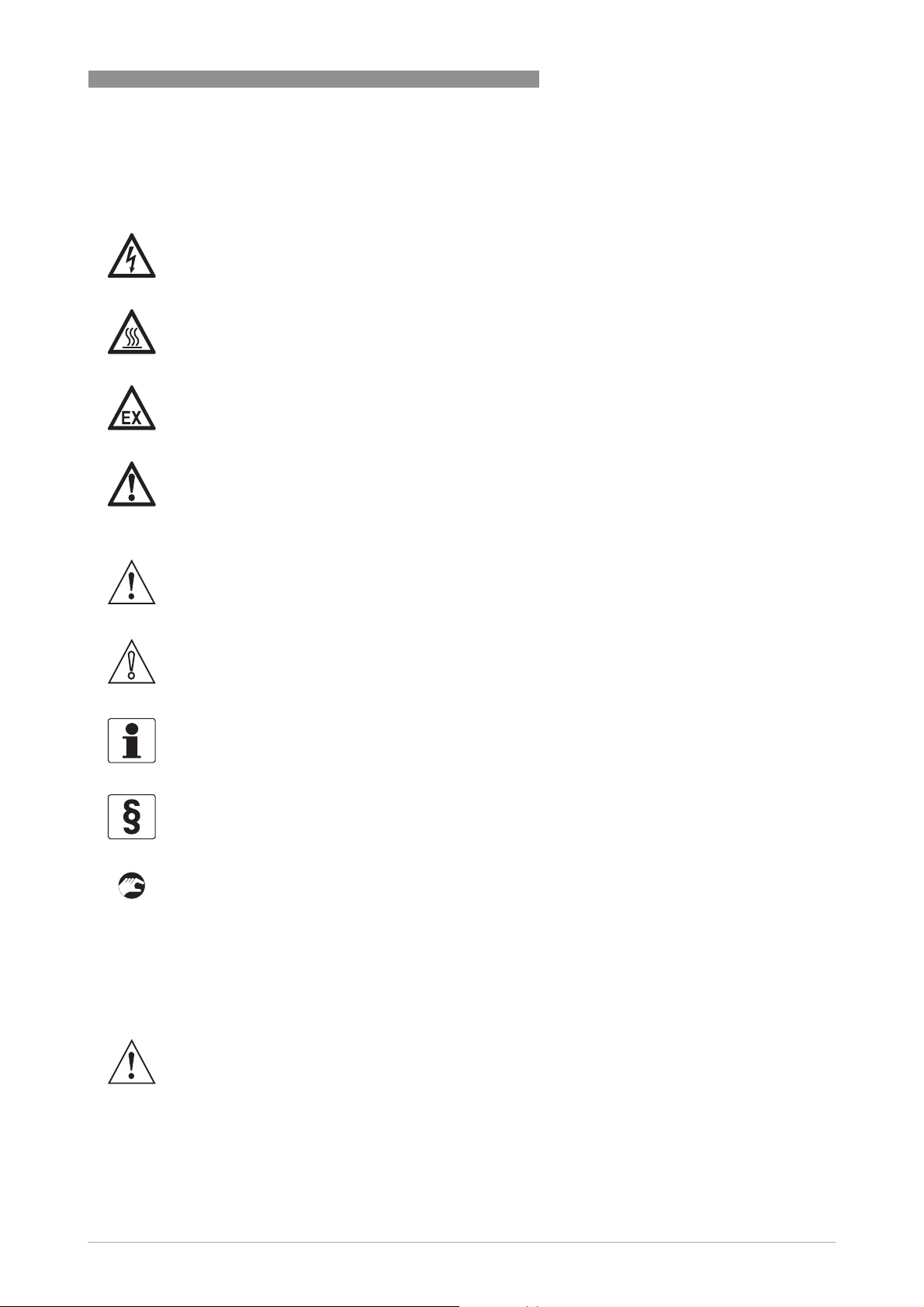
1.5.5 Warnings and symbols used
Safety warnings are indicated by the following symbols.
DANGER!
This warning refers to the immediate danger when working with electricity.
DANGER!
This warning refers to the immediate danger of burns caused by heat or hot surfaces.
DANGER!
This warning refers to the immediate danger when using this device in a hazardous atmosphere.
DANGER!
These warnings must be observed without fail. Even partial disregard of this warning can lead to
serious health problems and even death. There is also the risk of seriously damaging the device
or parts of the operator's plant.
SAFETY INSTRUCTIONS 1
WARNING!
Disregarding this safety warning, even if only in part, poses the risk of serious health problems.
There is also the risk of damaging the device or parts of the operator's plant.
CAUTION!
Disregarding these instructions can result in damage to the device or to parts of the operator's
plant.
INFORMATION!
These instructions contain important information for the handling of the device.
LEGAL NOTICE!
This note contains information on statutory directives and standards.
• HANDLING
HANDLING
HANDLINGHANDLING
This symbol designates all instructions for actions to be carried out by the operator in the
specified sequence.
i RESULT
RESULT
RESULTRESULT
This symbol refers to all important consequences of the previous actions.
1.6 Safety instructions for the operator
WARNING!
In general, devices from the manufacturer may only be installed, commissioned, operated and
maintained by properly trained and authorized personnel.
This document is provided to help you establish operating conditions, which will permit safe and
efficient use of this device.
www.krohne.com03/2014 - 4000172306 - HB OPTIFLEX 1300 R07 en
11
Page 12
2 DEVICE DESCRIPTION
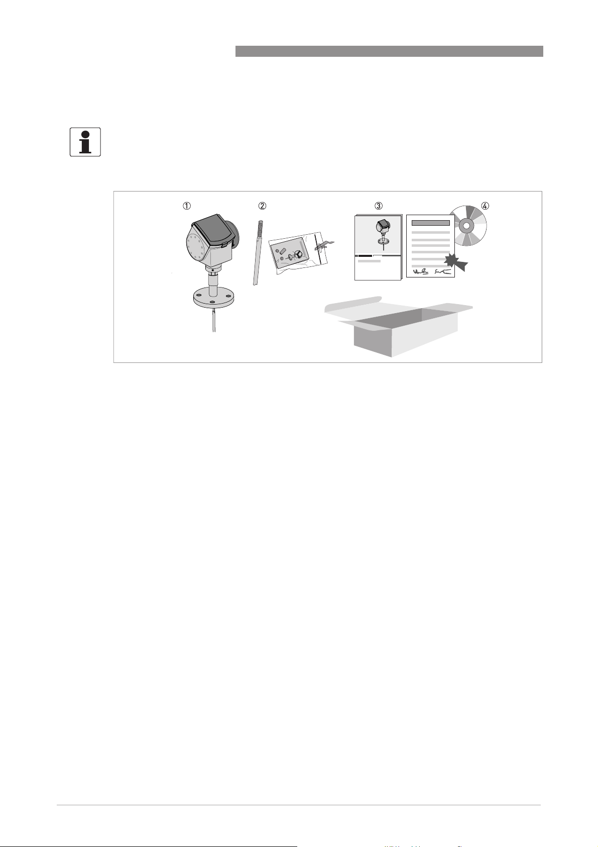
2.1 Scope of delivery
INFORMATION!
Do a check of the packing list to make sure that you have all the elements given in the order.
OPTIFLEX 1300 C
Figure 2-1: Scope of delivery for compact version
1 Signal converter and probe – compact version.
2 Probe segments. For the assembly procedure of the single rod probe, refer to
(single-piece probe)
option, only part of the probe is attached to the device. For the assembly procedure of the segmented single rod probe,
refer to
How to assemble the single rod probe (segmented probe)
mented coaxial probe, refer to
The assembly instructions and small parts are in a bag attached to the signal converter.
3 Quick Start
4 CD-ROM. This contains the Handbook, the Quick Start, the Technical Datasheet and related software.
on page 36. If a single rod or coaxial probe is attached and you ordered the "segmented probe"
on page 40. For the assembly procedure of the seg-
How to assemble the segmented coaxial probe
How to assemble the single rod probe
on page 43.
12
www.krohne.com 03/2014 - 4000172306 - HB OPTIFLEX 1300 R07 en
Page 13

OPTIFLEX 1300 C
Figure 2-2: Scope of delivery for the remote version
1 Signal converter and probe
2 Probe segments. For the assembly procedure of the single rod probe, refer to
(single-piece probe)
option, only part of the probe is attached to the device. For the assembly procedure of the segmented single rod, refer
to
coaxial probe, refer to
The assembly instructions and small parts are in a bag attached to the signal converter.
3 Quick Start
4 CD-ROM. This contains the Handbook, the Quick Start, the Technical Datasheet and related software.
5 Flexible conduit. For the assembly procedure, refer to
6 Wall bracket (also for installation on pipes)
on page 36. If a single rod or coaxial probe is attached and you ordered the "segmented probe"
How to assemble the single rod probe (segmented probe)
How to assemble the segmented coaxial probe
How to assemble the remote version
DEVICE DESCRIPTION 2
How to assemble the single rod probe
on page 40. For the assembly procedure of the segmented
on page 43.
on page 50.
INFORMATION!
No special tools, no training required!
www.krohne.com03/2014 - 4000172306 - HB OPTIFLEX 1300 R07 en
13
Page 14

2 DEVICE DESCRIPTION
2.2 Device description
The TDR level transmitter is designed to measure the distance, level, interface, mass and
volume of liquids, pastes, slurries, granulates and powders.
TDR level transmitters use a probe to guide a signal to the surface of the measured product. The
device has a large choice of probes. Thus, it can measure most products in difficult conditions.
For more data, refer to
The device has a set-up wizard, fully-potted electronic sub-assemblies and online help
functions. You usually will not need this document to install, set up and operate the device.
You can order these accessories:
• Stainless steel weather protection.
• RS232 / HART
®
• USB / HART
• ESD protection (30 kV).
• Metaglas
converter (VIATOR).
®
dual process sealing system for dangerous products.
Technical data
®
converter (VIATOR).
OPTIFLEX 1300 C
on page 127.
INFORMATION!
For more data on accessories, refer to List of accessories on page 182
.
14
www.krohne.com 03/2014 - 4000172306 - HB OPTIFLEX 1300 R07 en
Page 15

OPTIFLEX 1300 C
2.3 Visual Check
INFORMATION!
Inspect the packaging carefully for damages or signs of rough handling. Report damage to the
carrier and to the local office of the manufacturer.
DEVICE DESCRIPTION 2
Figure 2-3: Visual check
1 Device nameplate (for more data, refer to
2 Process connection data (size and pressure rating, material reference and heat number)
3 Gasket material data - refer to the illustration that follows
Figure 2-4: Symbols for the supplied gasket material (on the side of the process connection)
1 EPDM
2 Kalrez
®
6375
Non-Ex nameplate
on page 16)
If the device is supplied with an FKM/FPM gasket, there is no symbol on the side of the process
connection.
WARNING!
•
If the display screen glass is broken, do not touch.
•
If the device has to measure the level of dangerous products (ammonia etc.), we recommend
®
that the device has the Metaglas
•
If the device has to measure the level of products where there is a risk of electrostatic
option.
discharge, we recommend that the device has the ESD (electrostatic discharge) protection
option.
www.krohne.com03/2014 - 4000172306 - HB OPTIFLEX 1300 R07 en
15
Page 16

2 DEVICE DESCRIPTION
2.4 Nameplates
INFORMATION!
Look at the device nameplate to ensure that the device is delivered according to your order.
Check for the correct supply voltage printed on the nameplate.
2.4.1 Non-Ex nameplate
OPTIFLEX 1300 C
Figure 2-5: Non-Ex nameplate
1 Indicator arrow to cable entry / cable entry size
2 Nominal voltage for operation. For more data, refer to
3 Degree of ingress protection (according to EN 60529 / IEC 60529)
4 Customer tag number
5 Date of manufacture
6 Order number
7 Type code (defined in order)
8 Model name and number
9 Company name and address
Non-Ex devices
on page 57.
16
www.krohne.com 03/2014 - 4000172306 - HB OPTIFLEX 1300 R07 en
Page 17
OPTIFLEX 1300 C
3.1 General notes on installation
INFORMATION!
Inspect the packaging carefully for damages or signs of rough handling. Report damage to the
carrier and to the local office of the manufacturer.
INFORMATION!
Do a check of the packing list to make sure that you have all the elements given in the order.
INFORMATION!
Look at the device nameplate to ensure that the device is delivered according to your order.
Check for the correct supply voltage printed on the nameplate.
3.2 Storage
WARNING!
Do not keep the device in a vertical position. This will damage the probe and the device will not
measure correctly.
INSTALLATION 3
Figure 3-1: Storage conditions
1 Do not bend rod and coaxial probes – support here
2 Storage temperature range: -50…+85°C/ -60…+185°F (min. -40°C/ -40°F for devices with the integrated LCD display
option)
• Store the device in a dry and dust-free location.
• Store the device in its original packing.
www.krohne.com03/2014 - 4000172306 - HB OPTIFLEX 1300 R07 en
17
Page 18
3 INSTALLATION
3.3 Transport
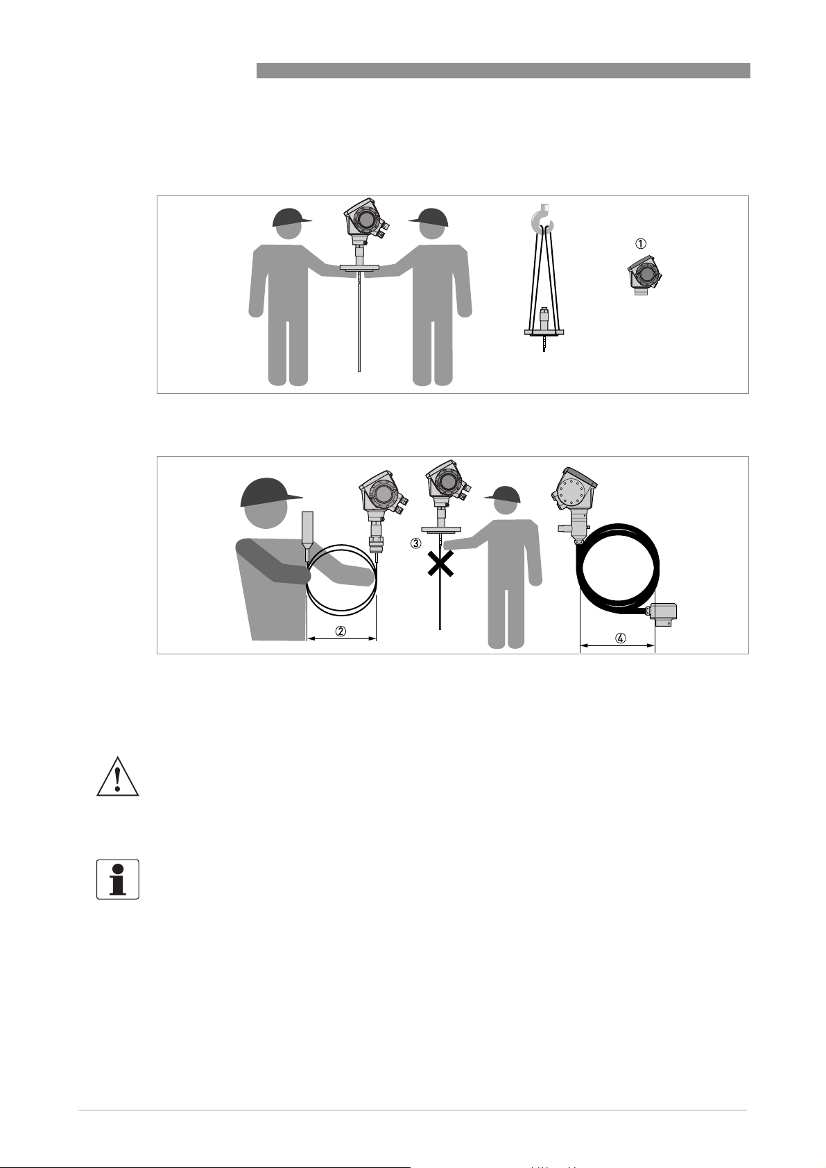
Figure 3-2: How to hold the device
OPTIFLEX 1300 C
Figure 3-3: How to hold the device
1 Remove the converter before you lift the device with a hoist.
2 Wind cable probes greater than 400 mm / 16¨ in diameter.
3 Do not hold the probe when you lift the device.
4 Do not wind the flexible conduit less than 330 mm / 13¨ in diameter.
WARNING!
If you do not lift the device carefully, you can cause damage to the probe.
3.4 Pre-installation requirements
INFORMATION!
Obey the precautions that follow to make sure that the device is correctly installed.
• Make sure that there is sufficient space on all sides.
• Protect the signal converter from direct sunlight. If necessary, install the weather protection
accessory.
• Do not subject the signal converter to heavy vibrations. The devices are tested for vibration
and agree with EN 50178 and IEC 60068-2-6.
18
www.krohne.com 03/2014 - 4000172306 - HB OPTIFLEX 1300 R07 en
Page 19
OPTIFLEX 1300 C
3.5 How to prepare the tank before you install the device
CAUTION!
To avoid measuring errors and device malfunction, obey these precautions.
3.5.1 Pressure and temperature ranges
INSTALLATION 3
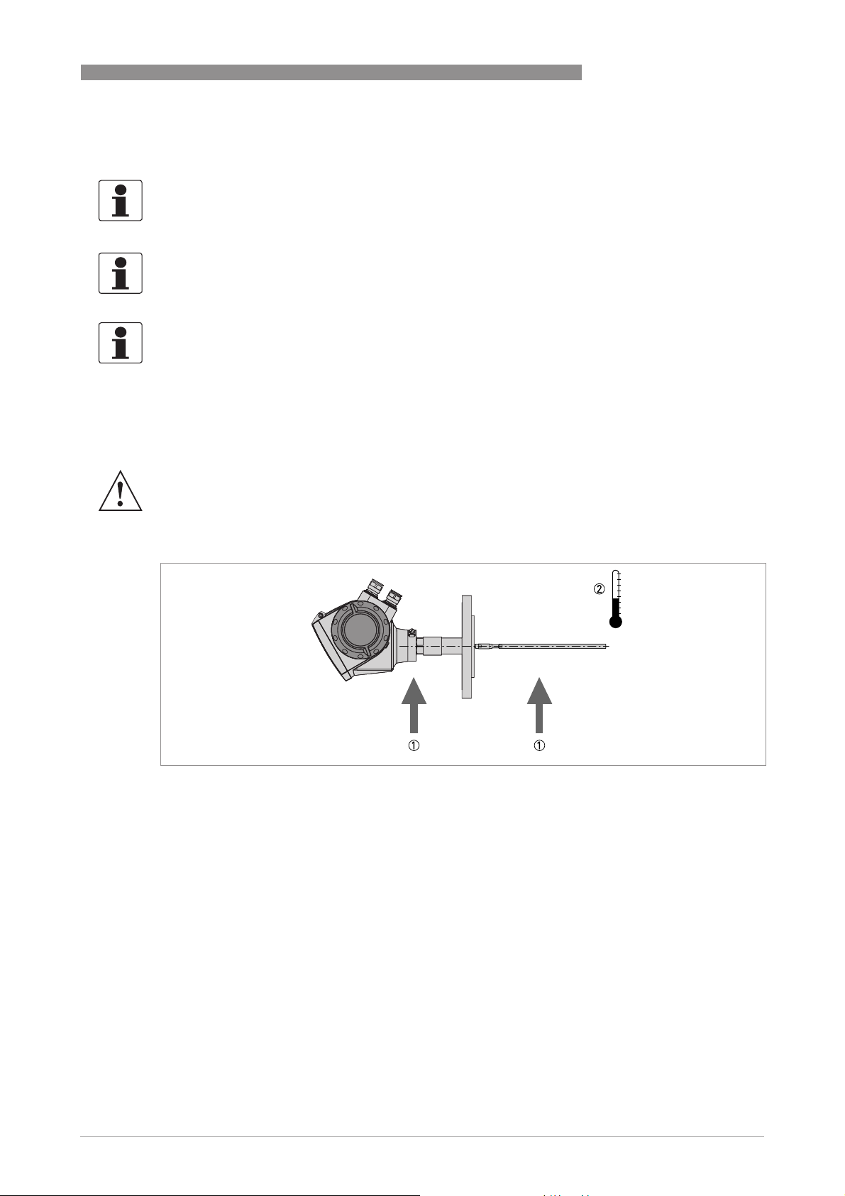
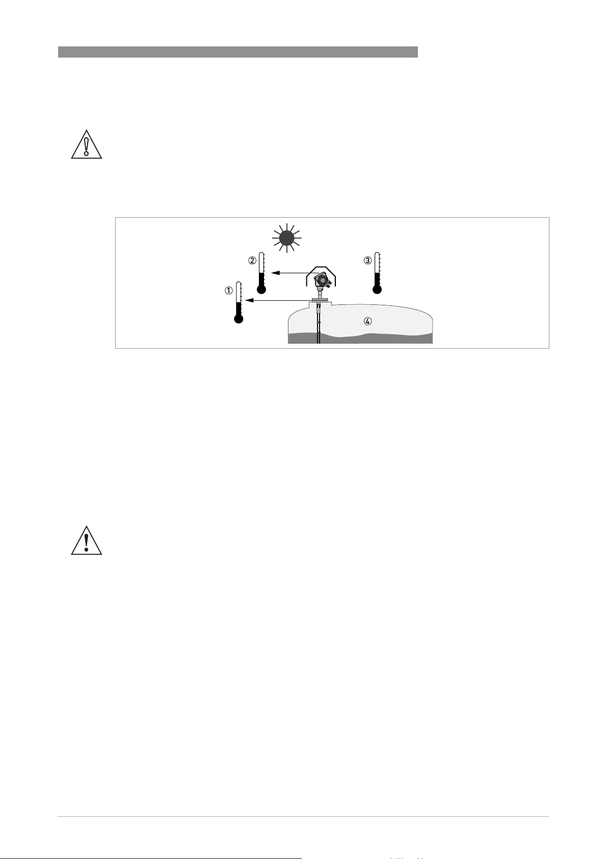
Figure 3-4: Pressure and temperature ranges
1 Process connection temperature
The process connection temperature must stay in the temperature range of the gasket material unless the device is
a High-Temperature version. Refer to the table "Temperature ranges for gaskets" that follows and to "Technical data"
on page 130.
Ex devices: see supplementary operating instructions
2 Ambient temperature for operation of the display
-20...+60°C / -5...+140°F
If the ambient temperature is not between these limits, the display screen switches off automatically
3 Ambient temperature
Non-Ex devices: -40...+80°C / -40...+176°F
Ex devices: see supplementary operating instructions
4 Process pressure
Refer to the table "Process pressure limits" that follows and "Pressure/temperature table for probe selection" on
page 136.
WARNING!
The process connection temperature range must agree with the temperature limits of the
gasket material. The operating pressure range is subject to the process connection used and the
flange temperature.
www.krohne.com03/2014 - 4000172306 - HB OPTIFLEX 1300 R07 en
19
Page 20
3 INSTALLATION
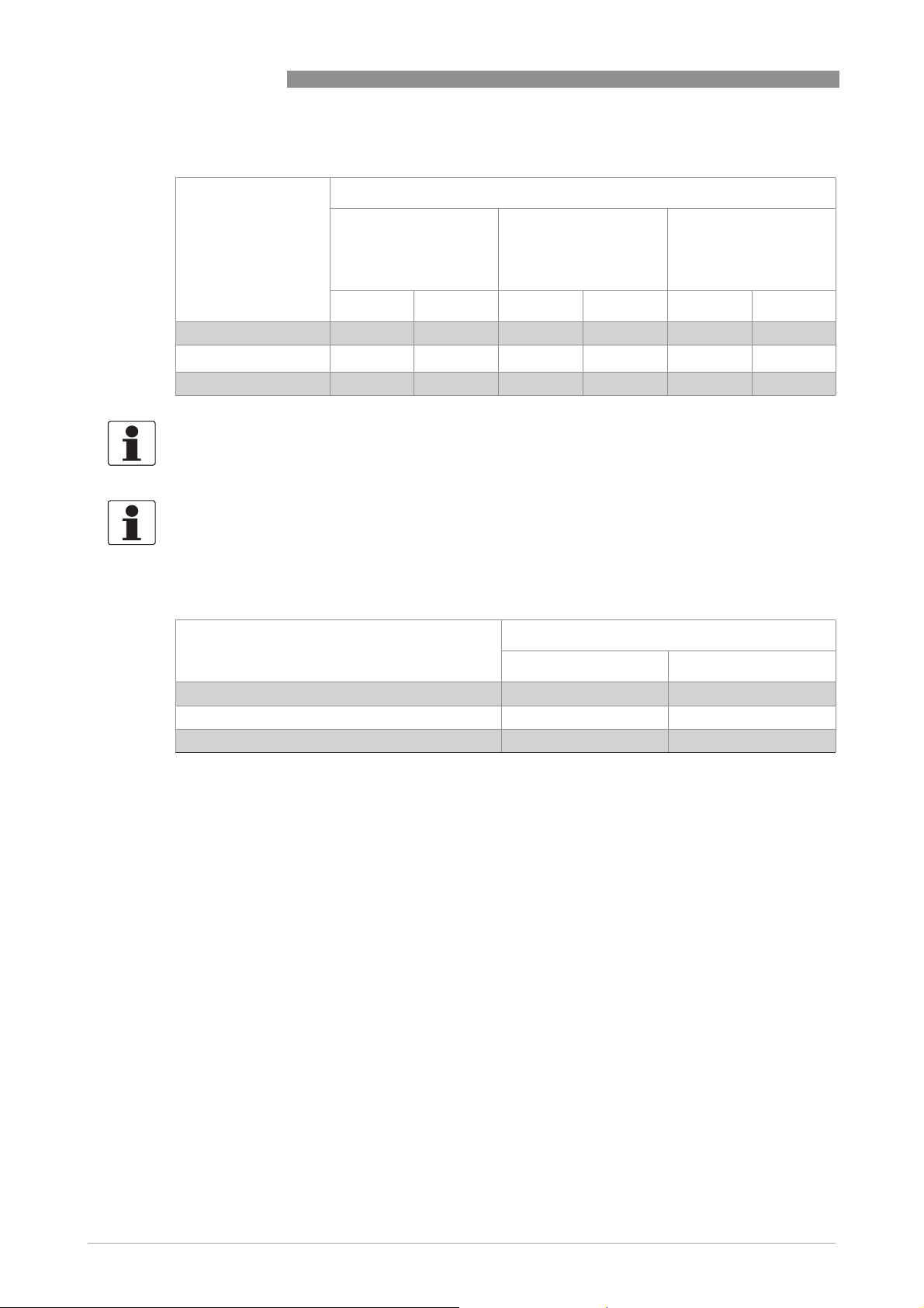
Temperature ranges for gaskets
Gasket material Process connection temperature
FKM/FPM -40…+200 -40…+392 -40…+150 -40…+302 -40…+300 -40…+572
Kalrez® 6375
EPDM -50…+150 -58…+302 -50…+150 -58…+302 -50…+250 -58…+482
INFORMATION!
Ø4 mm / 0.16
Ø4 mm / 0.16
Ø4 mm / 0.16Ø4 mm / 0.16
temperature range is -20...+150
INFORMATION!
Single rod probes with protective sheath option only:
Single rod probes with protective sheath option only: The process connection temperature range
Single rod probes with protective sheath option only:Single rod probes with protective sheath option only:
depends on the protective sheath material selected.
PP: -40...+90
¨
single cable probe with FEP coating option only:
single cable probe with FEP coating option only: The process connection
single cable probe with FEP coating option only: single cable probe with FEP coating option only:
°
C/ -40…+194°F; PVDF: -40...+150°C/ -40…+302°F; PVC: -15...+80°C/ +5…+176°F
OPTIFLEX 1300 C
Standard version High-Pressure version High-Temperature and
High-Temperature /
High-Pressure
versions
[°C] [°F] [°C] [°F] [°C] [°F]
-20…+200 -4…+392 -20…+150 -4…+302 -20…+300 -4…+572
°
C / -4...+302°F
Process pressure limits
Device version Maximum process pressure
[barg] [psig]
Ø8 mm / 0.32¨ single cable 40 1 580 1
High-Pressure (HP) version 300 1 4350 1
All other probe types and device versions 100 1 1450 1
1 Refer also to "Pressure / temperature table for probe selection" in the "Technical data" section
20
www.krohne.com 03/2014 - 4000172306 - HB OPTIFLEX 1300 R07 en
Page 21
OPTIFLEX 1300 C
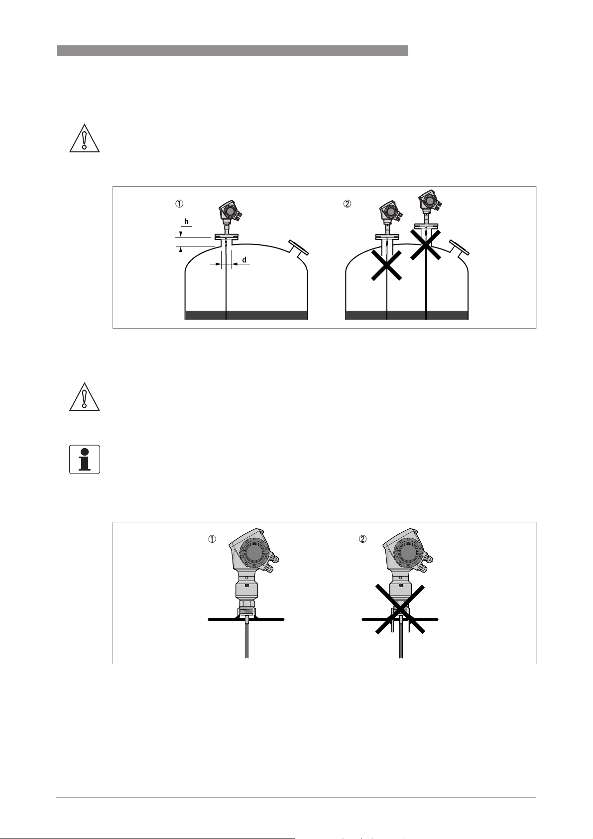
3.5.2 General information for nozzles
CAUTION!
Follow these recommendations to make sure that the device measures correctly.
Figure 3-5: Recommended nozzle dimensions for single rod and single cable probes
1 Recommended conditions: h ≤ d, where h is the height of the tank nozzle and d is the diameter of the tank nozzle.
2 The end of the nozzle must not have an extension into the tank. Do not install the device on a high nozzle.
INSTALLATION 3
CAUTION!
If the device is installed on a high nozzle, make sure that the probe does not touch the side of the
nozzle (attach the probe end, ...). We recommend that you use a coaxial probe (this solution is
applicable only to liquids).
INFORMATION!
It is possible to measure in these conditions with a minimum top dead zone. Use the snapshot
function to filter the parasite signals from long nozzles. For more data, refer to How to use the
snapshot function to filter parasitic signals on page 96
Figure 3-6: Sockets for threaded process connections
1 Recommended installation
2 The end of the socket must not have an extension into the tank
.
www.krohne.com03/2014 - 4000172306 - HB OPTIFLEX 1300 R07 en
21
Page 22
3 INSTALLATION
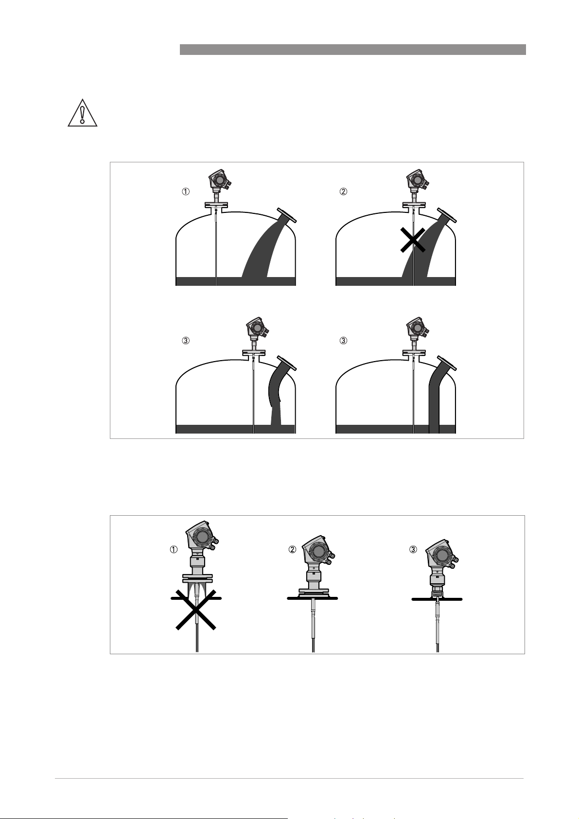
CAUTION!
Do not put the process connection near to the product inlet. If the product that enters the tank
touches the probe, the device will measure incorrectly.
OPTIFLEX 1300 C
Figure 3-7: Do not put the device near to a product inlet
1 The device is in the correct position.
2 The device is too near to the product inlet.
3 If it is not possible to put the device in the recommended position, install a deflector pipe.
Figure 3-8: How to prevent build-up of product around the process connection
1 If product particles are likely to collect in holes, a nozzle is not recommended.
2 Attach the flange directly to the tank.
3 Use a threaded connection to attach the device directly to the tank.
22
www.krohne.com 03/2014 - 4000172306 - HB OPTIFLEX 1300 R07 en
Page 23
OPTIFLEX 1300 C
INFORMATION!
If your device has a coaxial probe, you can ignore these installation recommendations.
CAUTION!
Install coaxial probes in clean liquids that are not too viscous.
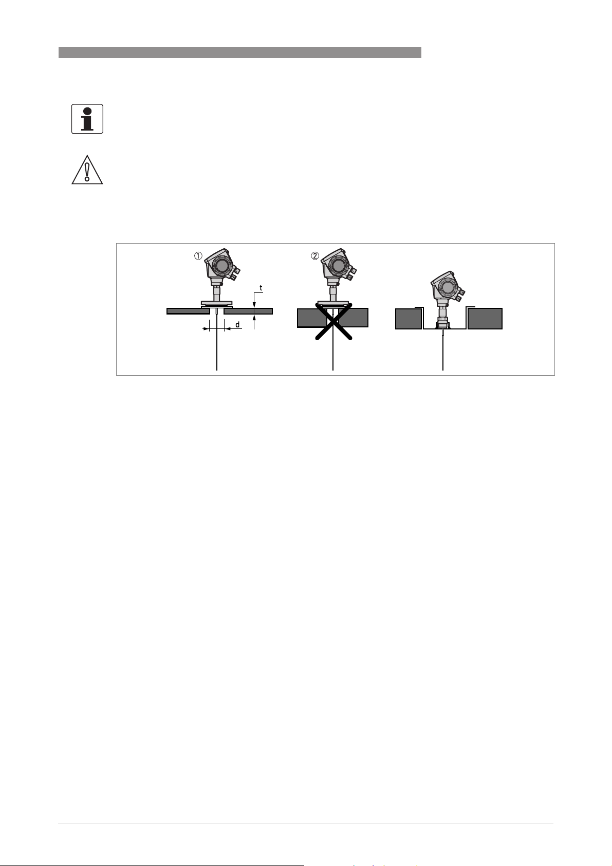
3.5.3 Installation requirements for concrete roofs
INSTALLATION 3
Figure 3-9: Installation on a concrete roof
1 The diameter, d, of the hole must be greater than the thickness, t, of the concrete.
2 If the thickness, t, of the concrete is greater than the diameter, d, of the hole, install the device in a recess.
www.krohne.com03/2014 - 4000172306 - HB OPTIFLEX 1300 R07 en
23
Page 24
3 INSTALLATION
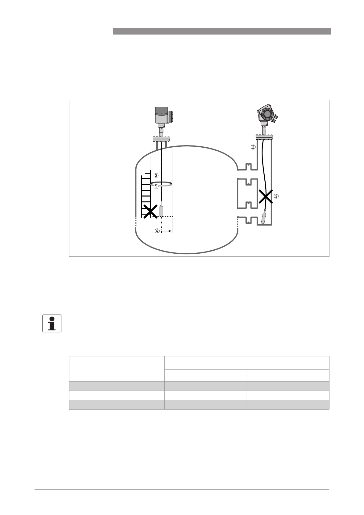
3.6 Installation recommendations for liquids
3.6.1 General requirements
OPTIFLEX 1300 C
Figure 3-10: Installation recommendations for liquids
1 The electromagnetic (EM) field generated by the device. It has a radius of R
objects and product flow. Refer to the table that follows.
2 If there are too many objects in the tank, install a bypass chamber or stilling well.
3 Keep the probe straight. If the probe is too long, shorten the probe length. Make sure that the device is configured with
the new probe length. For more data on the procedure, refer to
4 Empty space. Refer to the table that follows.
How to decrease the length of probes
. Make sure that the EM field is clear of
min
on page 98.
INFORMATION!
If the device has to measure the level of dangerous products (ammonia etc.), we recommend
®
that you use a device with the Metaglas
option.
Clearance between the probe and other objects in the tank
Probe type Empty space (radius, R
[mm] [inches]
Coaxial 0 0
Double rod / cable 100 4
Single rod / cable 300 12
), around the probe
min
24
www.krohne.com 03/2014 - 4000172306 - HB OPTIFLEX 1300 R07 en
Page 25
OPTIFLEX 1300 C
3.6.2 How to attach probes to the bottom of the tank
If the liquid is agitated or turbulent, you can attach the probe to the bottom of the tank. The
procedure to attach the probe depends on the type of probe used.
CAUTION!
Keep the probe straight.
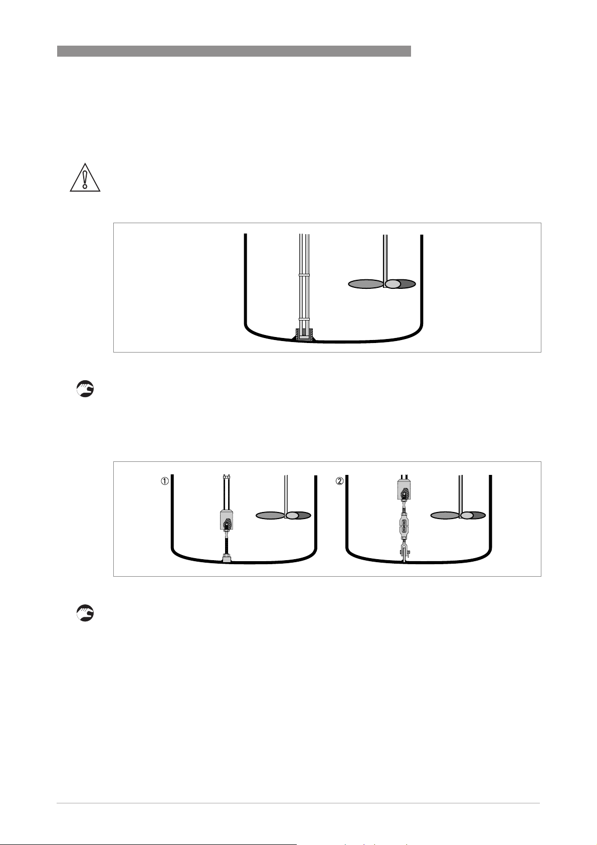
Double rod Ø8 mm / 0.32¨
INSTALLATION 3
Figure 3-11: How to attach a double rod probe to keep it straight
• Weld a tube with an internal diameter of 28...30 mm / 1.1...1.2¨ to the bottom of the tank.
i Make sure the tube aligns with the process connection at the top of the tank.
• Lower the probe into the tank.
• Put the end of the probe into the tube.
Double cable Ø4 mm / 0.16¨
Figure 3-12: How to attach a double cable probe to keep it straight
The probe counterweight has a hole with an M8 internal thread. You can also select the
appropriate options and attach:
1 An anchoring rod
2 A turnbuckle
For more data, contact your supplier.
www.krohne.com03/2014 - 4000172306 - HB OPTIFLEX 1300 R07 en
25
Page 26
3 INSTALLATION
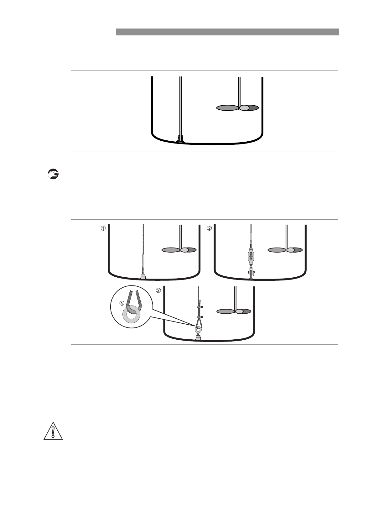
Single rod Ø8 mm / 0.32¨
Figure 3-13: How to attach a single rod probe to keep it straight
• Weld a tube with an internal diameter of 12 mm / 0.5¨ to the bottom of the tank.
i Make sure the tube aligns with the process connection at the top of the tank.
• Lower the probe into the tank.
• Put the end of the probe into the tube.
OPTIFLEX 1300 C
Single cable Ø4 mm / 0.16¨
Figure 3-14: How to attach a Ø4 mm / 0.16¨ single cable probe to keep it straight
1 Probe with threaded end
2 Probe with turnbuckle
3 Probe with chuck
4 If you chose a chuck to anchor the probe, we recommend that you fit a ferrule (metal sheath - not supplied) at the
bottom of the loop to prevent cable wear
26
The probe counterweight has a hole with an M8 internal thread. The other probe end options are
given in the illustration.
CAUTION!
If your device has a chuck, you must make the device recalculate the probe length. For the
procedure, refer to How to decrease the length of probes on page 98
. If the device does not
recalculate the probe length, it is possible that the device will not measure correctly.
www.krohne.com 03/2014 - 4000172306 - HB OPTIFLEX 1300 R07 en
Page 27
OPTIFLEX 1300 C
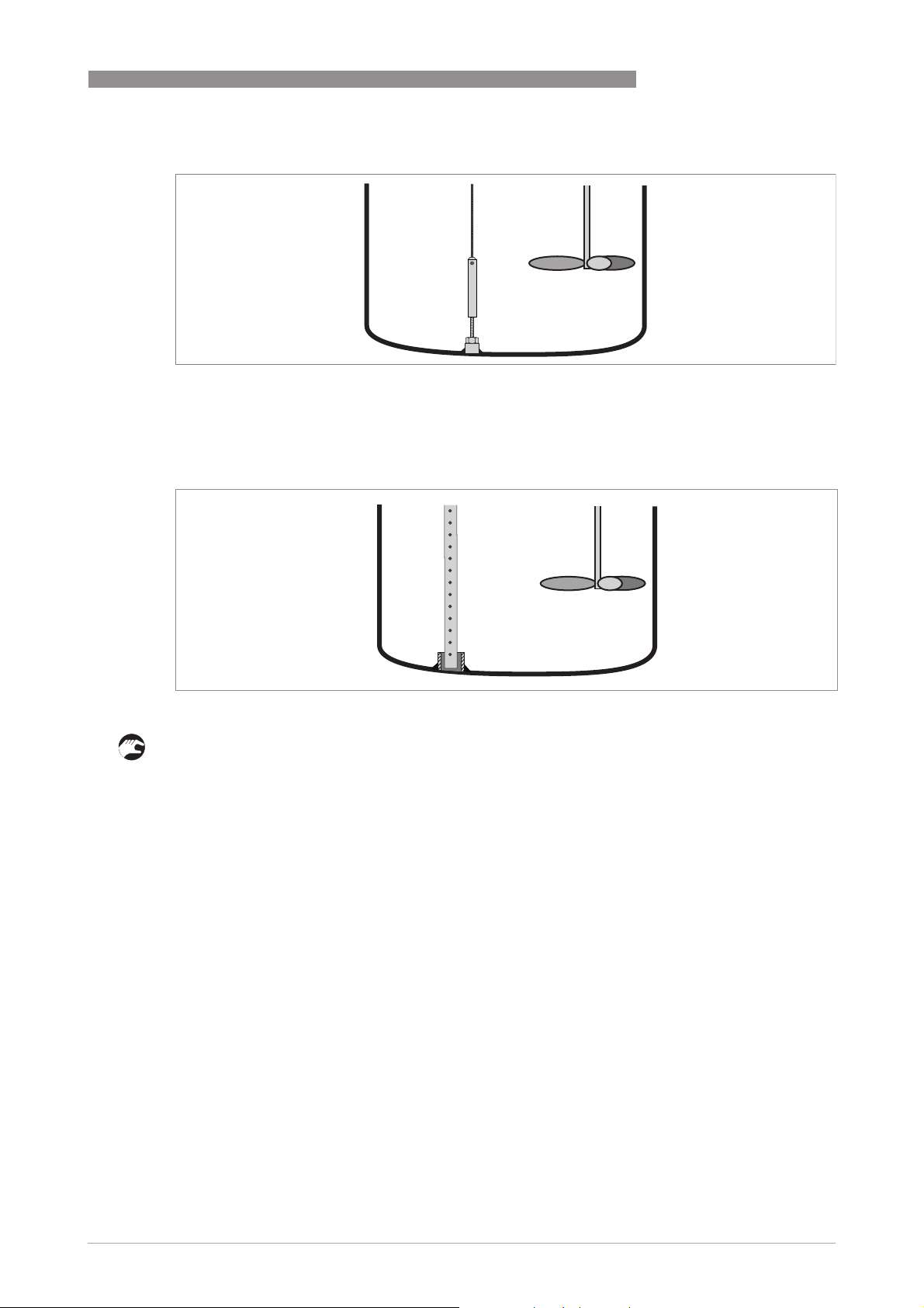
Single cable Ø2 mm / 0.08¨
Figure 3-15: How to attach a Ø2 mm / 0.08¨ single cable probe to keep it straight
The probe counterweight has a hole with an M8 internal thread. You can attach the probe
counterweight to a threaded end.
Coaxial Ø22 mm / 0.87¨
INSTALLATION 3
Figure 3-16: How to attach a coaxial probe to keep it straight
• Weld a tube with an internal diameter of 23...25 mm / 0.91...1¨ to the bottom of the tank.
i Make sure the tube aligns with the process connection at the top of the tank.
• Lower the probe into the tank.
• Put the end of the probe into the tube.
If this is not possible, you can attach braces to the probe.
www.krohne.com03/2014 - 4000172306 - HB OPTIFLEX 1300 R07 en
27
Page 28
3 INSTALLATION
3.6.3 Standpipes
Use a standpipe if:
• There is highly conductive foam in the tank.
• The liquid is very turbulent or agitated.
• There are too many other objects in the tank.
• The device is measuring a liquid (petro-chemicals) in a tank with a floating roof.
OPTIFLEX 1300 C
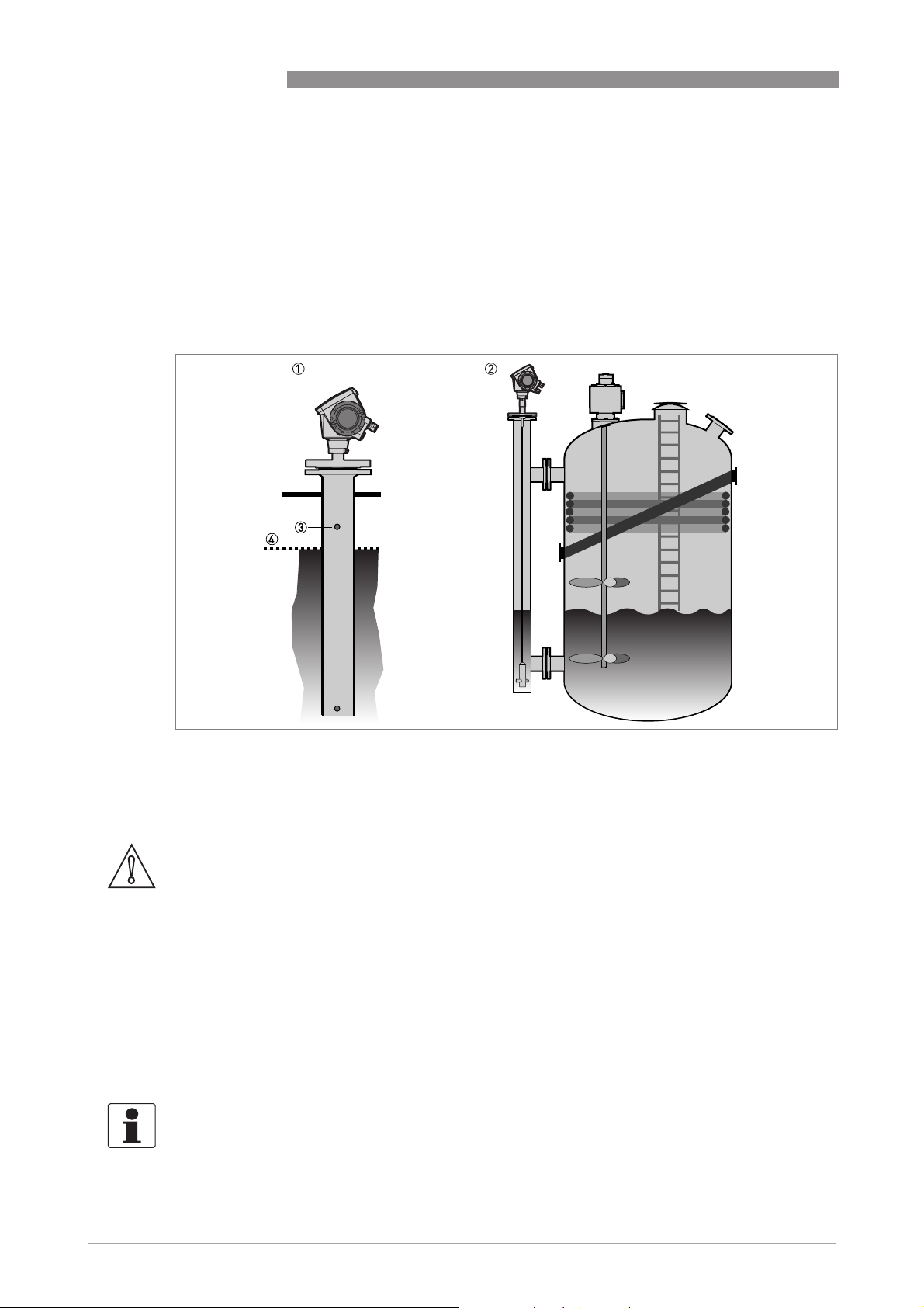
Figure 3-17: Basic installation recommendations for standpipes (stilling wells and bypass chambers)
1 Stilling well
2 Bypass chamber
3 Air circulation hole
4 Level of the liquid
CAUTION!
Installation requirements
•
The standpipe must be electrically conductive.
•
The standpipe must be straight. There must be no sudden changes in internal diameter
greater than 1 mm / 0.04
•
The standpipe must be vertical.
•
Recommended surface roughness: <±0.1 mm / 0.004¨.
•
Stilling well only: The bottom of the stilling well must be open.
•
Adjust the probe to the center of the standpipe.
•
Make sure that there are no deposits at the bottom of the standpipe.
•
Make sure that there is liquid in the standpipe.
INFORMATION!
Standpipes are not necessary for devices with coaxial probes. But if there is a sudden change in
diameter in the standpipe, we recommend that you install a device with a coaxial probe.
¨
.
28
www.krohne.com 03/2014 - 4000172306 - HB OPTIFLEX 1300 R07 en
Page 29
OPTIFLEX 1300 C
INSTALLATION 3
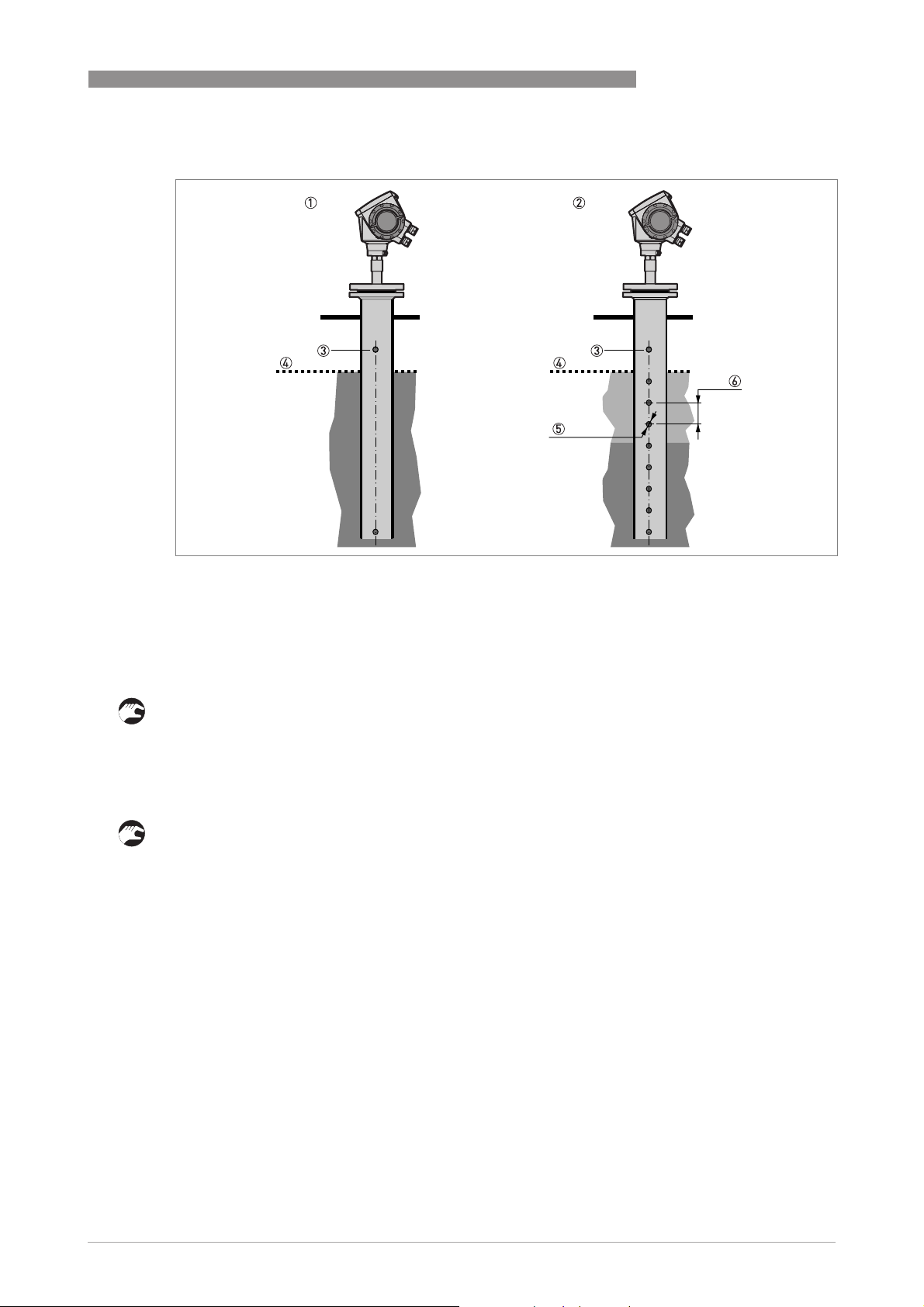
Figure 3-18: Installation recommendations for stilling wells
1 Stilling well in tanks containing one liquid
2 Stilling well in tanks containing more than one liquid
3 Air circulation hole
4 Maximum level of the liquid
5 Liquid circulation hole
6 Distance between holes ≥ 25 mm/1¨ (depends on the minimum layer to be measured)
Installation in tanks containing one liquid and foam
• Drill a pressure equalization hole in the stilling well above the maximum level.
• Deburr the hole.
• If the probe has a counterweight, make sure that there is enough space between the
counterweight and the wall of the stilling well.
Installation in tanks containing more than one liquid
• Drill a pressure equalization hole in the stilling well above the maximum level of the top liquid.
• Drill more holes along the length of the stilling well. Distance between holes ≥ 25 mm / 1¨
(depends on the minimum layer to be measured)
i These holes help the liquids to move freely.
• Deburr the holes.
• If the probe has a counterweight, make sure that there is enough space between the
counterweight and the wall of the stilling well.
Floating roofs
If the device is for a tank with a floating roof, install it in a stilling well.
www.krohne.com03/2014 - 4000172306 - HB OPTIFLEX 1300 R07 en
29
Page 30

3 INSTALLATION
OPTIFLEX 1300 C
Figure 3-19: Floating roofs
1 Sediment
2 Support fixtures
3 Stilling well
4 Floating roof
5 Product
6 Tank
Bypass chamber - general notes
30
Figure 3-20: Installation recommendations for bypass chambers
1 Bypass chamber for tanks that contain one liquid
2 Bypass chamber for tanks that contain more than one liquid
3 Distance between holes ≤ minimum level of each liquid in the tank
4 Additional process connection
www.krohne.com 03/2014 - 4000172306 - HB OPTIFLEX 1300 R07 en
Page 31

OPTIFLEX 1300 C
Installation on tanks containing one liquid and foam
• The bypass chamber must have a process connection that is above the maximum level of
liquid.
• The bypass chamber must have a process connection that is below the lowest measured level
of liquid.
Installation on tanks containing more than one liquid
• The bypass chamber must have a process connection that is above the maximum level of
liquid.
• The bypass chamber must have a process connection that is below the lowest measured level
of liquid.
• There must be more process connections along the length of the bypass chamber. These
must have a minimum diameter of 25 mm / 1¨ with a minimum distance of 100 mm / 4¨
between the holes.
• If the probe has a counterweight, make sure that there is enough space between the
counterweight and the wall of the stilling well.
• If the interface liquid does not have a layer of air above it, fit a vent at the top of the bypass
chamber. Refer to the illustration that follows:
INSTALLATION 3
Figure 3-21: Installation recommendations for bypass chambers with no air gap
1 Bypass chamber with no air gap
2 Air vent
www.krohne.com03/2014 - 4000172306 - HB OPTIFLEX 1300 R07 en
31
Page 32

3 INSTALLATION
3.6.4 Typical applications
Spherical tanks
The device can measure liquid petroleum gas (LPG). This product is stocked in spherical tanks.
OPTIFLEX 1300 C
Figure 3-22: A spherical tank
Figure 3-23: How to install the device on a spherical tank
1 Install the device on top of the tank
2 If the top platform has the shape of a nozzle, do not install the process connection too near to the wall. For more data,
refer to
General requirements
on page 24.
32
www.krohne.com 03/2014 - 4000172306 - HB OPTIFLEX 1300 R07 en
Page 33

OPTIFLEX 1300 C
Horizontal cylindrical tanks
The installation requirements and procedures for vertical tanks are also applicable to horizontal
cylindrical tanks.
CAUTION!
Calculate volume and mass values carefully for conversion tables. Volume does not increase in
the same proportion as level.
INSTALLATION 3
Figure 3-24: How to install the device in a horizontal cylindrical tank
www.krohne.com03/2014 - 4000172306 - HB OPTIFLEX 1300 R07 en
33
Page 34

3 INSTALLATION
3.7 Installation recommendations for solids
3.7.1 Nozzles on conical silos
We recommend that you prepare the installation when the silo is empty.
DANGER!
Risk of electrostatic discharge (ESD): The device is resistant to electrostatic discharges of up to
15 kV (30 kV with the ESD protection option
responsibility of the fitter and the user to prevent ESD.
CAUTION!
Install the device at the correct location to measure level correctly and prevent too much
bending and traction. If necessary, attach the probe to the bottom of the tank.
–
recommended for solid applications), but it is the
OPTIFLEX 1300 C
34
Figure 3-25: Installation recommendations for solids
1 We recommend installation without a nozzle. If not, h ≤50 mm / 2¨.
2 The end of the probe must be more than 300 mm / 12¨ above the tank bottom.
3 Empty space (radius, R
4 The electromagnetic (EM) field generated by the device. It is also the measurement zone of the probe. Make sure that
the EM field is clear of objects and product flow.
5 Ground the tank, the product and the probe (if attached).
6 If possible, put the process fitting ≥300 mm / 12¨ from the tank wall
) around the probe.
min
www.krohne.com 03/2014 - 4000172306 - HB OPTIFLEX 1300 R07 en
Page 35

OPTIFLEX 1300 C
Clearance between the probe and other objects in the tank
INSTALLATION 3
Probe type Empty space (radius, R
Single cable Ø4 mm / 0.16¨ 4 300 12
Single cable Ø8 mm / 0.32¨ 4 300 12
INFORMATION!
If the probe is longer than 10 m / 33 ft, we recommend that you do not attach the end of the
probe.
3.7.2 Traction loads on the probe
Traction load depends on:
• The height and shape of the tank.
• The particle size and density.
• The rate at which the tank is emptied.
CAUTION!
Risk of damage to the cable probe. High loads can break the cable.
If the load on the Ø8 mm / 0.32
supplier.
) around the probe
min
[mm] [inches]
¨
single cable probe is more than 3500 kg / 7700 lb, contact your
CAUTION!
Make sure that the tank roof is resistant to deformation at high loads.
Estimated traction load on the probe in kg
Material Probe length, 10 m Probe length, 20 m Probe length, 30 m
[kg]
Cement 1000 2000 3000
Fly ash 500 1000 1500
Wheat 300 500 1200
Estimated traction load on the probe in lb
Material Probe length, 33 ft Probe length, 65 ft Probe length, 98 ft
[lb]
Cement 2200 4410 6520
Fly ash 1100 2200 3300
Wheat 660 1100 2650
www.krohne.com03/2014 - 4000172306 - HB OPTIFLEX 1300 R07 en
35
Page 36

3 INSTALLATION
3.8 How to install the device on the tank
3.8.1 How to assemble the single rod probe (single-piece probe)
INFORMATION!
This procedure is for devices with single rod probes that are not segmented (single-piece
probes).
OPTIFLEX 1300 C
Figure 3-26: Equipment needed to assemble the device
1 Union nut
2 2 locking nuts
3 Housing assembly
4 Single rod probe
5 Tools: two 8 mm open-ended wrenches (not supplied)
6 Tools: one 7 mm open-ended wrench (not supplied)
36
www.krohne.com 03/2014 - 4000172306 - HB OPTIFLEX 1300 R07 en
Page 37

OPTIFLEX 1300 C
INSTALLATION 3
Figure 3-27: Check the order number on each component
• Make sure that the housing assembly and the single rod have the same ID numbers.
• Remove the sticker from the probe.
www.krohne.com03/2014 - 4000172306 - HB OPTIFLEX 1300 R07 en
37
Page 38

3 INSTALLATION
OPTIFLEX 1300 C
Figure 3-28: How to attach the locking nut and union nut
• Attach a locking nut to the housing assembly.
• Make sure that the nut is fully engaged on the thread.
• Attach the union nut to the housing assembly.
• Tighten these nuts with the two 8 mm open-ended wrenches.
• Continue the assembly procedure on the page that follows.
38
www.krohne.com 03/2014 - 4000172306 - HB OPTIFLEX 1300 R07 en
Page 39

OPTIFLEX 1300 C
INSTALLATION 3
Figure 3-29: How to attach the single rod probe to the flange assembly
CAUTION!
Support the probe.
• Attach a locking nut to the single rod.
• Make sure that the locking nut is engaged ¾ along the length of the thread.
• Attach the single rod to the union nut. Make sure the probe touches the housing assembly.
• Tighten the single probe with a 7 mm open-ended wrench (step 9).
• Tighten the locking nut against the union nut with two 8 mm open-ended wrenches (step 10).
www.krohne.com03/2014 - 4000172306 - HB OPTIFLEX 1300 R07 en
39
Page 40

3 INSTALLATION
3.8.2 How to assemble the single rod probe (segmented probe)
INFORMATION!
This procedure is for devices with single rod probes that are segmented.
OPTIFLEX 1300 C
Figure 3-30: Equipment needed to assemble the single rod probe (segmented)
1 Converter and process connection
2 Bottom (quantity: 1) segment of the rod probe
3 Top and middle (if more than one) segments of the rod probe
4 Tools: two 8 mm open-end wrenches (not supplied)
5 Lock nuts (2 lock nuts per segment)
6 Union nut (1 union nut per segment)
40
www.krohne.com 03/2014 - 4000172306 - HB OPTIFLEX 1300 R07 en
Page 41

OPTIFLEX 1300 C
INSTALLATION 3
Figure 3-31: How to assemble the segmented single rod probe: part 1
CAUTION!
Make sure that the nuts are tight and the rod probe cannot loosen.
• Attach a lock nut to the threaded rod below the process connection. Turn the nut until it is ¾
along the length of the rod.
• Attach a union nut to the threaded rod below the process connection.
• Use two 8 mm open-end wrenches to tighten the union nut against the lock nut.
www.krohne.com03/2014 - 4000172306 - HB OPTIFLEX 1300 R07 en
41
Page 42

3 INSTALLATION
OPTIFLEX 1300 C
Figure 3-32: How to assemble the segmented single rod probe: part 2
WARNING!
Put a support below the probe to prevent deformation.
CAUTION!
Make sure that the nuts are tight and the rod probe cannot loosen.
• Attach a lock nut to each end of the rod probe segments.
• Attach a union nut to the bottom end of each rod probe segment, but not to the bottom
segment. Use two 8 mm open-end wrenches to tighten the union nut against the lock nut.
• Attach the top segment of the rod probe to the union nut below the process connection. Use
two 8 mm open-end wrenches to tighten the union nut against the lock nut on the rod probe.
• Attach the middle segment of the rod probe to the union nut on the top segment (if there are
middle segments). Use two 8 mm open-end wrenches to tighten the union nut against the lock
nut. Repeat this step for the other segments.
• Attach the bottom segment of the rod probe to the union nut on the top segment. Use two
8 mm open-end wrenches to tighten the union nut against the lock nut.
42
www.krohne.com 03/2014 - 4000172306 - HB OPTIFLEX 1300 R07 en
Page 43

OPTIFLEX 1300 C
CAUTION!
Make sure that the length of the probe is correct. If the probe is too long, refer to How to
decrease the length of probes on page 98
.
3.8.3 How to assemble the segmented coaxial probe
INSTALLATION 3
Figure 3-33: Equipment needed to assemble the coaxial probe
1 Converter and process connection
2 HC M4×20 screws (1 screw per probe segment)
3 Lock washers (1 pair of washers per probe segment)
4 Top (quantity: 1), middle (quantity: 1 or more) and bottom (quantity: 1) segments of the signal rod
5 PTFE spacer (1 spacer per probe segment)
6 Middle (quantity: 1 or more) and bottom (quantity: 1) segments of the coaxial tube
7 Union nut with 2 socket set screws M5×5 (1 union nut per segment of the coaxial tube)
8 Tools: two 7 mm open-end wrenches (not supplied)
9 Tools: two pipe (Stillson) wrenches (not supplied)
10 Tools: one 2.5 mm Allen wrench and one 2 mm Allen wrench (not supplied)
www.krohne.com03/2014 - 4000172306 - HB OPTIFLEX 1300 R07 en
43
Page 44

3 INSTALLATION
OPTIFLEX 1300 C
Figure 3-34: How to assemble the segmented coaxial probe: part 1
CAUTION!
Do not attach the screw to the end of the rod segment that has a groove for the attachment of a
PTFE spacer.
• Use a 2 mm Allen wrench to attach and tighten a HC M4×20 screw at the top of each rod
segment (intermediary and end rod segments)
• Attach a PTFE spacer to the end of each rod segment that has a groove.
• Attach a pair of lock washers at the top of each rod segment (intermediary and end rod
segments)
• Assemble one of the middle rod segments (with a pair of lock washers on the attached screw)
and the signal rod below. Use two 7 mm open-ended wrenches to tighten the assembled parts
to a torque of 2…3Nm.
44
www.krohne.com 03/2014 - 4000172306 - HB OPTIFLEX 1300 R07 en
Page 45

OPTIFLEX 1300 C
INSTALLATION 3
Figure 3-35: How to assemble the segmented coaxial probe: part 2
WARNING!
Be careful when you use the pipe wrenches. Make sure that the measuring tubes have no
deformation.
CAUTION!
•
Make sure that the screws are tight and the measuring tube cannot loosen.
•
Make sure that the fitting for the lock screw is not aligned with a hole in the coaxial tube.
• Attach a union nut to each coaxial tube (middle and end tubes)
• Attach a middle tube segment to the coaxial probe stem. Do not use tools to tighten the
assembled parts.
• Assemble the next middle rod segment (with a pair of lock washers on the attached screw)
and the top rod segment. Use two 7 mm open-ended wrenches to tighten the assembled parts
to a torque of 2…3Nm.
• Assemble the next coaxial tube segment and the top coaxial tube segment. Do not use tools to
tighten the assembled parts. Do steps (9) thru (10) again until the end rod segment and end
coaxial tube are attached.
• Use the 2 pipe wrenches to tighten the coaxial tubes in the lock nuts.
• Use a 2.5 mm Allen wrench to attach and tighten the two HC M5×5 screws (lock screws) to the
union nut.
www.krohne.com03/2014 - 4000172306 - HB OPTIFLEX 1300 R07 en
45
Page 46

3 INSTALLATION
3.8.4 How to install a device with a flange connection
Equipment needed:
• Device
• Gasket (not supplied)
• Wrench (not supplied)
OPTIFLEX 1300 C
Figure 3-36: Flange connection
• Make sure that the flange on the nozzle is level.
• Make sure that you use the applicable gasket for the flange and the process.
• Align the gasket correctly on the flange facing of the nozzle.
• Lower the probe carefully into the tank.
i For more data on cable probes, refer to
• Tighten the flange bolts.
How to install a cable probe in the tank
i Refer to local rules and regulations for the correct torque to apply to the bolts.
on page 48.
46
www.krohne.com 03/2014 - 4000172306 - HB OPTIFLEX 1300 R07 en
Page 47

OPTIFLEX 1300 C
3.8.5 How to install a device with a threaded connection
Equipment needed:
• Device
• Gasket (not supplied)
• 50 mm / 2¨ wrench (not supplied)
INSTALLATION 3
Figure 3-37: Threaded connection
• Make sure the tank connection is level.
• Make sure that you use the applicable gasket for the connection and the process.
• Align the gasket correctly.
• If the device is installed on a tank made of plastic or other non-conductive material, refer to
Recommendations for pits and tanks made of non-conductive materials
• Lower the probe carefully into the tank.
i For more data on cable probes, refer to
• Use 50 mm / 2¨ wrench to attach the process connection to the tank.
• Tighten the nut.
How to install a cable probe in the tank
on page 49.
on page 48.
i Refer to local rules and regulations for the correct torque to apply to the connection.
INFORMATION!
If there is not sufficient clearance to install the device, remove the housing. Install the probe and
then put the housing back on the process connection. For more data, refer to How to turn or
remove the signal converter on page 53
.
www.krohne.com03/2014 - 4000172306 - HB OPTIFLEX 1300 R07 en
47
Page 48

3 INSTALLATION
3.8.6 How to install a cable probe in the tank
Figure 3-38: Wind cable probes carefully
1 Do not wind cable probes less than 400 mm / 16¨ in diameter.
WARNING!
If you bend the probe too much, you will damage the device and it will not measure accurately.
OPTIFLEX 1300 C
48
Figure 3-39: Installation of devices with cable probes
1 >1 m / 3½ ft
• Use two persons to lift the housing and the probe above the process connection.
• Hold the device 1 m / 3½ ft above the tank.
• Unwind the probe carefully into the tank.
www.krohne.com 03/2014 - 4000172306 - HB OPTIFLEX 1300 R07 en
Page 49

OPTIFLEX 1300 C
INSTALLATION 3
3.8.7 Recommendations for pits and tanks made of non-conductive materials
If you have a device with a single rod or a single cable probe and a thread connection,
obey these instructions:
• Put a metal sheet between the device and the process connection.
i It must have a diameter greater than 200 mm / 8¨.
• Make sure that the metal sheet is in contact with the thread stop on the device.
We recommend that you use DN≥200 / ≥8¨ for flange connections.
If you have a device with a double rod, double cable or coaxial probe, you can ignore these
instructions.
Figure 3-40: Installation in a non-metallic tank or pit with a thread connection
1 Non-metallic (plastic...) tank or pit
2 Metal sheet, Ø ≥200 mm / 8¨
CAUTION!
When the device is installed, make sure that the tank roof has no deformation.
www.krohne.com03/2014 - 4000172306 - HB OPTIFLEX 1300 R07 en
49
Page 50

3 INSTALLATION
3.8.8 How to assemble the remote version
OPTIFLEX 1300 C
Figure 3-41: Part 1 of assembly procedure
• Attach the wall bracket 1 to the flexible conduit.
• Tighten the locking nut 2 with a 24 mm wrench.
• Attach the wall bracket to a wall or pipe (DN50...100 / 2¨...4¨) 3.
• Loosen the housing locking screw 4 with a 5 mm Allen wrench.
• Remove the housing 5.
50
www.krohne.com 03/2014 - 4000172306 - HB OPTIFLEX 1300 R07 en
Page 51

OPTIFLEX 1300 C
INSTALLATION 3
Figure 3-42: Part 2 of the assembly procedure
• Attach the housing to the flexible conduit 6.
• Tighten the housing locking screw 7.
• Attach the flexible conduit to the probe 8.
• Tighten the flexible conduit locking screw 9.
www.krohne.com03/2014 - 4000172306 - HB OPTIFLEX 1300 R07 en
51
Page 52

3 INSTALLATION
You can attach the wall bracket of the remote housing to a wall or pipe (DN50...100 / 2¨...4¨).
These are the dimensions:
Figure 3-43: Dimensions of the wall bracket
Dimensions in mm
OPTIFLEX 1300 C
Dimensions [mm]
a b c d e f g h i j
Wall bracket 120 60 20 11 90 150 6 67.4 126.4 150.4
Dimensions in inches
Dimensions [inches]
a b c d e f g h i j
Wall bracket 4.7 2.4 0.8 0.4 3.5 5.9 0.2 2.65 4.98 5.92
52
www.krohne.com 03/2014 - 4000172306 - HB OPTIFLEX 1300 R07 en
Page 53

OPTIFLEX 1300 C
3.8.9 How to turn or remove the signal converter
The converter turns 360°. The converter can be removed from the process connection assembly
under process conditions.
INSTALLATION 3
Figure 3-44: How to turn or remove the signal converter
1 Tool: 5 mm Allen wrench (not supplied) for the lock screw on the signal converter
2 Cover for the coaxial hole on top of the process connection assembly (not supplied)
CAUTION!
If you remove the housing, put a cover on the the coaxial hole on top of the process connection
assembly.
When the housing is attached to the process connection assembly, tighten the lock screw with
the 5 mm Allen wrench 1.
www.krohne.com03/2014 - 4000172306 - HB OPTIFLEX 1300 R07 en
53
Page 54

3 INSTALLATION
3.8.10 How to attach the weather protection to the device
Equipment needed:
• Device
• Weather protection (option)
• 10 mm wrench (not supplied)
Refer to "Technical data: Dimensions and weight", for the overall dimensions of the weather
protection.
OPTIFLEX 1300 C
Figure 3-45: Installation of the weather protection
• Loosen the bracket nuts on the weather protection. Remove the bracket.
• Lower the weather protection onto the device. Turn the weather protection so that the keyhole
points forward.
• Attach the bracket.
• Lift the weather protection to the top of the housing support pillar. Hold the weather
protection in the correct position and tighten the bracket nuts.
54
www.krohne.com 03/2014 - 4000172306 - HB OPTIFLEX 1300 R07 en
Page 55

OPTIFLEX 1300 C
3.8.11 How to open the weather protection
Equipment needed:
• Weather protection attached to the device.
• Large slotted tip screwdriver (not supplied).
INSTALLATION 3
Figure 3-46: How to open the weather protection
1 Weather protection in its closed position
2 Weather protection in its open position. Minimum clearance in front of the device: 300 mm / 12¨.
• Put a large slotted tip screwdriver into the keyhole at the front of the weather protection. Turn
the screwdriver counterclockwise.
• Pull the top of weather protection up and forward.
i This will open the weather protection.
www.krohne.com03/2014 - 4000172306 - HB OPTIFLEX 1300 R07 en
55
Page 56

4 ELECTRICAL CONNECTIONS
4.1 Safety instructions
DANGER!
All work on the electrical connections may only be carried out with the power disconnected. Take
note of the voltage data on the nameplate!
DANGER!
Observe the national regulations for electrical installations!
DANGER!
For devices used in hazardous areas, additional safety notes apply; please refer to the Ex
documentation.
WARNING!
Observe without fail the local occupational health and safety regulations. Any work done on the
electrical components of the measuring device may only be carried out by properly trained
specialists.
OPTIFLEX 1300 C
INFORMATION!
Look at the device nameplate to ensure that the device is delivered according to your order.
Check for the correct supply voltage printed on the nameplate.
4.2 Electrical installation: outputs 1 and 2
56
Figure 4-1: Electrical installation
1 Terminal compartment cover
2 Output 1: current output -
3 Output 1: current output +
4 Grounding terminal in the housing
5 Output 2: current output - (option)
6 Output 2: current output + (option)
7 Grounding terminal between the process connection and the converter
Output 1 energizes the device and is used for HART® communication. If the device has the
second current output option, use a separate power supply to energize output 2.
www.krohne.com 03/2014 - 4000172306 - HB OPTIFLEX 1300 R07 en
Page 57

OPTIFLEX 1300 C
ELECTRICAL CONNECTIONS 4
Procedure:
• Remove the housing terminal compartment cover 1.
• Connect the wires to the device. Obey the national electrical codes.
• Make sure that the polarity of the wires is correct.
• Attach the ground to 4 or 7. Both terminals are technically equivalent.
INFORMATION!
If the polarity is not correct, this will not cause damage to the device. But the device will not
operate and the output will be 0 mA.
4.3 Electrical connection for current output
4.3.1 Non-Ex devices
Figure 4-2: Electrical connections for non-Ex devices
1 Power supply
2 Resistor for HART
3 Output 1: 14...30 VDC for an output of 22 mA at the terminal
4 Output 2: 10...30 VDC for an output of 22 mA at the terminal
®
communication
4.3.2 Devices for hazardous locations
DANGER!
For electrical data for device operation in hazardous locations, refer to the related certificates of
compliance and supplementary instructions (ATEX, IECEx, FM, CSA, ...). You can find this
documentation on the DVD-ROM delivered with the device or it can be downloaded free of charge
from the website (Download Center).
www.krohne.com03/2014 - 4000172306 - HB OPTIFLEX 1300 R07 en
57
Page 58

4 ELECTRICAL CONNECTIONS
4.4 Protection category
INFORMATION!
The device fulfils all requirements per protection category IP 66/67. It also fulfils all
requirements per NEMA type 4X (housing) and type 6P (probe).
DANGER!
Make sure that the cable gland is watertight.
OPTIFLEX 1300 C
Figure 4-3: How to make the installation agree with protection category IP 67
• Make sure that the gaskets are not damaged.
• Make sure that the electrical cables are not damaged.
• Make sure that the electrical cables agree with the national electrical code.
• The cables are in a loop in front of the device 1 so water does not go into the housing.
• Tighten the cable feedthroughs 2.
• Close unused cable feedthroughs with dummy plugs 3.
58
www.krohne.com 03/2014 - 4000172306 - HB OPTIFLEX 1300 R07 en
Page 59

OPTIFLEX 1300 C
4.5 Networks
4.5.1 General information
The device uses the HART® communication protocol. This protocol agrees with the HART®
Communication Foundation standard. The device can be connected point-to-point. It can also
operate in a multi-drop network of up to 15 devices.
The device output is factory-set to communicate point-to-point. To change the communication
mode from point-to-point
4.5.2 Point-to-point networks
point-to-point to multi-drop
point-to-pointpoint-to-point
ELECTRICAL CONNECTIONS 4
multi-drop, refer to
multi-dropmulti-drop
Network configuration
on page 86.
Figure 4-4: Point-to-point connection (non-Ex)
1 Address of the device (0 for a point-to-point connection)
2 4...20 mA + HART
3 Resistor for HART® communication
4 Power supply
5 HART
6 HART
®
modem
®
communication device
®
www.krohne.com03/2014 - 4000172306 - HB OPTIFLEX 1300 R07 en
59
Page 60

4 ELECTRICAL CONNECTIONS
4.5.3 Multi-drop networks
OPTIFLEX 1300 C
Figure 4-5: Multi-drop network (non-Ex)
1 Address of the device (n+1 for multidrop networks)
2 Address of the device (1 for multidrop networks)
3 4mA + HART
4 Resistor for HART® communication
5 Power supply
6 HART
7 HART
®
®
modem
®
communication device
60
www.krohne.com 03/2014 - 4000172306 - HB OPTIFLEX 1300 R07 en
Page 61

OPTIFLEX 1300 C
5.1 Start-up checklist
Check these points before you energize the device:
• Are all the wetted components (probe, process connection and gaskets) chemically resistant
to the product in the tank?
• Does the information on the signal converter nameplate agree with the operating data?
• Did you correctly install the device on the tank?
• Do the electrical connections agree with the national electrical codes?
DANGER!
If the device has a Hazardous Locations approval, make sure that the device and the installation
agrees with the requirements of the certificate of compliance.
5.2 Operating concept
You can read measurements and configure the device with:
• A digital display screen (optional).
• A connection to a system or PC with PACTware™. You can download the Device Type
Manager (DTM) file from the website. It is also supplied on the DVD-ROM delivered with the
device.
• A connection to a system or PC with AMS™. You can download the Device Description (DD)
file from the website. It is also supplied on the DVD-ROM delivered with the device.
• A connection to a HART
file from the website. It is also supplied on the DVD-ROM delivered with the device.
START-UP 5
®
Field Communicator. You can download the Device Description (DD)
www.krohne.com03/2014 - 4000172306 - HB OPTIFLEX 1300 R07 en
61
Page 62

5 START-UP
5.3 Digital display screen
5.3.1 Local display screen layout
OPTIFLEX 1300 C
Figure 5-1: Local display screen layout
1 Error / Warning icon
2 Tag number or menu name
3 Selected menu item (gray text cannot be selected)
4 []/ []: scroll up/scroll down
5 Keypad buttons (refer to the table below)
5.3.2 Keypad buttons
For data on keypad functions, refer to
Keypad button Description
Right [>>>>]
Enter [^^^^]
Down []
Up []
Esc (Escape) [>>>>] + []
Operator mode
on page 65.
5.3.3 Help screens
When you are in supervisor mode, the local display helps you to configure the device. If you do
not touch any keys after 30 seconds, a help message is displayed. This will explain what the
menu is and what the parameters do. Push [>>>>] and [] (Esc) at the same time to go back to the
menu. If you do not touch the display for another 30 seconds, the message is shown again.
62
www.krohne.com 03/2014 - 4000172306 - HB OPTIFLEX 1300 R07 en
Page 63

OPTIFLEX 1300 C
5.3.4 How to start the device
• Connect the converter to the power supply.
• Energize the converter.
i After 30 seconds the screen will display "booting up", "starting up" and then the default
screen will appear.
• The device will display readings.
i Measurements agree with specifications given in the customer order.
CAUTION!
If the manufacturer received information about the installation, the device will display readings
correctly. If not, refer to the quick setup procedures on page 73
5.4 Remote communication with PACTware™
PACTware™ displays measurement information clearly and lets you configure the device from a
remote location. It is an Open Source, open configuration software for all field devices. It uses
Field Device Tool (FDT) technology. FDT is a communication standard for sending information
between the system and the field device. This standard agrees with IEC 62453. Field devices are
easily integrated. Installation is supported by a user-friendly Wizard.
START-UP 5
.
Install these software programs and equipment:
• Microsoft® .NET Framework version 1.1 or later.
• PACTware.
• HART
• The Device Type Manager for the device.
The software and installation instructions are given on the DVD-ROM supplied with the device.
You can also download the latest version of PACTware™ and the DTM from our website.
Refer also to the PACTware™ consortium site at http://www.pactware.com.
®
converter (USB, RS232...).
www.krohne.com03/2014 - 4000172306 - HB OPTIFLEX 1300 R07 en
63
Page 64

5 START-UP
OPTIFLEX 1300 C
Figure 5-2: Screen from the PACTware™ user interface
1 DTM menu
2 Basic measurement information: level, current output and device status
3 Information for device identification
4 Configuration summary
5.5 Remote communication with the AMS™ Device Manager
The AMS™ Device Manager is an industrial Plant Asset Management (PAM) software tool. Its
role is to:
• Store configuration information for each device.
• Support HART® devices.
• Store and read process data.
• Store and read diagnostic status information.
• Help plan preventive maintenance to reduce a plant's downtime to a minimum.
The DD file is given on the DVD-ROM supplied with the device. You can also download it from our
website.
64
www.krohne.com 03/2014 - 4000172306 - HB OPTIFLEX 1300 R07 en
Page 65

OPTIFLEX 1300 C
6.1 User modes
Operator
Operator This mode displays measurement data. For more data, refer to
OperatorOperator
Supervisor
Supervisor Use this mode to view parameters, commission the device, create tables
SupervisorSupervisor
6.2 Operator mode
The operator can choose what information to display.
This section shows you:
• What each button does in operator mode.
• What special function each button has if it is pressed for more than 1 second.
• How to move from one screen of information to another.
OPERATION 6
on page 65.
mode
for volume or mass measurement, change critical values to measure in
difficult process conditions. To get access to the supervisor menu, refer to
Protection of the device settings
refer to
Function description
on page 86. For more data on menu items,
on page 73.
Operator
Some data (volume, mass etc.) will only be available if the device is correctly configured by the
supervisor, as described below.
Devices with the "second output" option can display 2 values on the % current output screen (for
example: level and interface level). Devices must also have the "interface" option for interface
measurement.
Functions of keypad buttons in operator mode
Keypad button Description Normal function "Hot key" function
Right Change display style 1 Enter program mode 2
Enter – Enter signal screen editing mode
Down Change measurement parameter 4The screen shown at this time
Up Change measurement parameter 4Display language will change to
Esc (Escape) – –
1 Value, value and picture, or value and bar graph
2 Push this button for 1 second
3 Push this button after the selection of the signal screen. For more data, refer to "Operation: How to make the device
follow the correct level or interface signal".
4 Level, distance, volume etc.
5 Push this button for 3 seconds. Push the button again and it will go back to the original language.
3
becomes the default screen 2
English 5
www.krohne.com03/2014 - 4000172306 - HB OPTIFLEX 1300 R07 en
65
Page 66

6 OPERATION
Information screens for a device with 1 output
OPTIFLEX 1300 C
Text and image
screen
Go to % current output
screen
Go to Text screen Go to
[] []
Level [>>>>] <Output 1:
Output Function> 1
[>>>>] Level [>>>>] (Text
and
image)
[]/ [] []/ []
Interface Level 2 [>>>>] <Output 1:
Output Function> 1
[>>>>] Interface Level 2 [>>>>] (Text
and
image)
[]/ [] []/ []
Distance [>>>>] <Output 1:
Output Function>
1
[>>>>] Distance [>>>>] (Text
and
image)
[]/ [] []/ []
Interface Distance 2 [>>>>] <Output 1:
Output Function> 1
[>>>>] Interface Distance 2 [>>>>] (Text
and
image)
[]/ [] []/ []
Layer 2 [>>>>] <Output 1:
Output Function> 1
[>>>>] Layer 2 [>>>>] (Text
and
image)
[]/ [] []/ []
Volume (Mass) 3 [>>>>] <Output 1:
Output Function> 1
[>>>>] Volume (Mass) 3 [>>>>] (Text
and
image)
[]/ [] []/ []
Interface Volume
(Interface Mass) 4
[>>>>] <Output 1:
Output Function> 1
[>>>>] Interface Volume
(Interface Mass) 4
[>>>>] (Text
and
image)
[]/ [] []/ []
Ullage Volume
(Ullage Mass) 3
[>>>>] <Output 1:
Output Function> 1
[>>>>] Ullage Volume
(Ullage Mass) 3
[]/ [] []/ []
Layer Volume
(Layer Mass) 4
[>>>>] <Output 1:
Output Function> 1
[>>>>] Layer Volume
(Layer Mass) 4
[] []/ []
Back to the top of the
Signal screen 5
list
[]
Back to the top of the
list
1 Refer to the Operation: Function description section (Table C. Advanced setup, menu item C.3.1 Output Function)
2 This screen is for devices with the "interface" option only
3 This data is only available if you created a volume table (or a mass table). Refer to the Conversion menu in supervisor
mode (Quick Setup > Setup Mode > Conversion).
4 This screen is for devices with the "interface" option only. This data is only available if you created a volume table (or
a mass table). Refer to the Conversion menu in supervisor mode (Quick Setup > Setup Mode > Conversion).
5 This screen shows voltage amplitude of return signals against distance. It is used for finding level and interface when
there are interference signals. Push [>] to move the cursor from one signal peak to another.
66
www.krohne.com 03/2014 - 4000172306 - HB OPTIFLEX 1300 R07 en
Page 67

OPTIFLEX 1300 C
Information screens for a device with the second output option
OPERATION 6
Text and image
screen
[] []
Level [>>>>] <Output 1: output
[]/ [] []/ []
Distance [>>>>] <Output 1:
[]/ [] []/ []
Layer 2 [>>>>] <Output 1:
[]/ [] []/ []
Volume (Mass) 3 [>>>>] <Output 1:
[]/ [] []/ []
Ullage Volume
(Ullage Mass) 3
[]/ [] []/ []
Layer Volume
(Layer Mass) 4
[] []/ []
Back to the top of the
list
1 Refer to the Operation: Function description section (Table C. Advanced setup, menu item C.3.1 Output Function (out-
put 1) and C.4.1 Output Function (output2))
2 This screen is for devices with the "interface" option only
3 This data is only available if you created a volume table (or a mass table). Refer to the Conversion menu in supervisor
mode (Quick Setup > Setup Mode > Conversion).
4 This screen is for devices with the "interface" option only. This data is only available if you created a volume table (or
a mass table). Refer to the Conversion menu in supervisor mode (Quick Setup > Setup Mode > Conversion).
5 This screen shows voltage amplitude of return signals against distance. This is used for finding level and interface
when there are interference signals. Push [>] to move the cursor from one signal peak to another.
Go to % current output
screen
function>
<Output 2: Output
Function> 1
Output Function>
<Output 2:
Output Function> 1
Output Function>
<Output 2:
Output Function> 1
Output Function>
<Output 2:
Output Function> 1
[>>>>] <Output 1:
Output Function>
<Output 2:
Output Function> 1
[>>>>] <Output 1:
Output Function>
<Output 2:
Output Function> 1
Go to Text screen Go to
[>>>>] Level [>>>>] (Text
[>>>>] Distance [>>>>] (Text
[>>>>] Layer 2 [>>>>] (Text
[>>>>] Volume (Mass) 3 [>>>>] (Text
[>>>>] Ullage Volume
(Ullage Mass) 3
[>>>>] Layer Volume
(Layer Mass) 4
Signal screen 5
[]
Back to the top of the
list
and
image)
and
image)
and
image)
and
image)
[>>>>] (Text
and
image)
[>>>>] (Text
and
image)
www.krohne.com03/2014 - 4000172306 - HB OPTIFLEX 1300 R07 en
67
Page 68

6 OPERATION
6.3 Supervisor mode
6.3.1 General notes
OPTIFLEX 1300 C
Configure your device in Supervisor
• Use the Quick Setup
Setup menus, refer to
• Use the Advanced Setup
about menu items, refer to
• Save Quick Links
items A.2 to A.6), refer to
• Error finding and troubleshooting procedures are described in the Test
about the test menu, refer to
Quick Setup menus to configure your device quickly. For more data about Quick
Quick SetupQuick Setup
Advanced Setup menu to find single items for device configuration. For more data
Advanced SetupAdvanced Setup
Quick Links for items that you use regularly. For more data about quicklinks (menu
Quick LinksQuick Links
Supervisor mode. You can:
SupervisorSupervisor
Function description
Function description
Function description
Function description
6.3.2 How to get access to the supervisor mode
Do the steps that follow:
• Push the [>>>>] button for one second.
i This displays the login screen.
• Push the [] or [] buttons to select Supervisor
• Push the [^^^^] button.
i The screen displays where to type in the password.
• Type in the password. The factory-set password is [>>>>], [^^^^], [], [], [>>>>], [^^^^].
i The device displays the message "Login successful" and then the main menu for supervisor
mode.
Supervisor from the list.
SupervisorSupervisor
on page 73 (Table A. Quick setup).
on page 73 (Table C. Advanced setup).
on page 73 (Table A. Quick setup).
Test menu. For more data
TestTest
on page 73 (Table B. Test).
You can change the password for the supervisor mode (menu item C.5.2.2). For more data, refer
to
Function description
on page 73 (Table C. Advanced setup).
The main menu shows:
• Quick Setup menu.
• Test menu.
• Advanced Setup menu.
You cannot select "Service menu" in supervisor mode. Menus that can be selected are in black
text. Menus that cannot be selected are in gray text.
If you go back to operator mode, you will have access to the supervisor mode, without password
security, for 30 minutes.
68
www.krohne.com 03/2014 - 4000172306 - HB OPTIFLEX 1300 R07 en
Page 69

OPTIFLEX 1300 C
6.3.3 Keypad functions
Menu navigation
Figure 6-1: Menu navigation
1 Menu selection bar
2 Header bar
3 Menu list
4 Menu item that is not available (in gray text)
OPERATION 6
>
This is what you see when you are in the list of menus in supervisor mode. The functions of the
buttons are given in the table that follows:
Function of keypad buttons in the menu lists
Keypad button Description Function
Right Go to the next menu level
Enter -
Down Move the menu selection bar down the list
Up Move the menu selection bar up the list
Esc (Escape) Go back to the menu level you were on before
www.krohne.com03/2014 - 4000172306 - HB OPTIFLEX 1300 R07 en
69
Page 70

6 OPERATION
Lists of parameters in menu items
Figure 6-2: Lists of parameters in menu items
1 Parameter selection bar
2 Menu name
3 Parameter used at this time
OPTIFLEX 1300 C
>
This is what you see when you choose a menu item that has a list of parameters. The functions of
the buttons are given in the table that follows:
Function of keypad buttons in menu items that have a list of parameters
Keypad button Description Function
Right -
Enter Select the parameter and go back to the menu
Down Move the menu selection bar down the list
Up Move the menu selection bar up the list
Esc (Escape) Go back to the menu 1
1 This does not confirm that you selected a new parameter
70
www.krohne.com 03/2014 - 4000172306 - HB OPTIFLEX 1300 R07 en
Page 71

OPTIFLEX 1300 C
Values in menu items
Figure 6-3: Values in menu items
1 Maximum value
2 Minimum value
3 Cursor on the digit to be changed
4 Menu name
5 Illustration of menu item
6 Error message
OPERATION 6
This is what you see when you choose a menu item that has a value. The functions of the buttons
are given in the table that follows:
Function of keypad buttons in menu items that have values
Keypad button Description Function
Right Move the cursor to the next digit on the right
Enter Select the parameter and go back to the menu
Down Decrease the digit value
Up Increase the digit value
Esc (Escape) Go back to the menu 1
1 This does not confirm that you selected a new parameter
www.krohne.com03/2014 - 4000172306 - HB OPTIFLEX 1300 R07 en
71
Page 72

6 OPERATION
If you push the buttons for 1 second, you can use these hotkey functions:
Hotkey functions in supervisor mode
Button Description Function
1 Make a selection from the Advanced Setup menu list
2 Push this button for 3 seconds
How to save settings
• When you have changed parameters in all the necessary menu items, push [^^^^] to accept the
new parameter.
• Push [>>>>] and [] at the same time to go back to the Save settings
• The device will ask you to save or cancel your settings. Select Save
or Cancel
Cancel to reject them.
CancelCancel
i The display goes back to operator mode.
Right Create a quick link 1
Enter -
Down -
Up Screen displays information in English 2
Esc (Escape) Go back to the operator mode
Save settings screen.
Save settingsSave settings
Save to accept the new settings
SaveSave
OPTIFLEX 1300 C
6.3.4 Menu overview
A Quick Setup
A.1 Setup Mode
A.2 Quick Link 1 (default: Error Records)
A.3 Quick Link 2 (default: Contrast)
A.4 Quick Link 3 (default: Language)
A.5 Quick Link 4 (default: Length Unit)
A.6 Quick Link 5 (default: Display Mode)
B Test
B.1 Test
B.2 Information
C Advanced Setup
C.1 Installation Setup
C.3 Output 1 (HART)
C.4 Output 2 (Passive) 1
C.5 Device Setup
C.6 Reset
1 Optional
72
www.krohne.com 03/2014 - 4000172306 - HB OPTIFLEX 1300 R07 en
Page 73

OPTIFLEX 1300 C
6.3.5 Function description
A. Quick Setup
OPERATION 6
Menu
Step Function Function description Selection list Default
No.
A.1 Setup Mode
A.1.1
A.1.1 Complete
A.1.1A.1.1
A.1.2
A.1.2 Application
A.1.2A.1.2
1 Probe Type Read only
2 Product Type:
3 Air Gap Flag: Do
4 Number Of
5 Top Product Liquid:
6 Application Type:
7 Are the products
8 Settings summary
9 Current changes
A.1.3
A.1.3 Installation
A.1.3A.1.3
1 Tank Height The distance from the tank
2 Installation Type The type of process connection
3A Stillwell Height The height from the tank
4A Stillwell Diameter The inner diameter of the
Complete This follows the steps given in
CompleteComplete
Application Follow this procedure to
ApplicationApplication
Which application
do you have?
you have air or gas
above the product?
Products: How
many different
products do you
have in the tank?
What do you want
to measure?
mixed or unmixed?
must be saved or
cancelled before
proceeding
Installation Follow this procedure to
InstallationInstallation
This follows the steps given in
This follows the steps given in This follows the steps given in
the Application, Installation,
the Application, Installation,
the Application, Installation, the Application, Installation,
Conversion and Output setup
Conversion and Output setup
Conversion and Output setup Conversion and Output setup
modes.
modes.
modes.modes.
Follow this procedure to
Follow this procedure to Follow this procedure to
describe the tank contents.
describe the tank contents.
describe the tank contents.describe the tank contents.
The application. Liquid, Solid Depends on
This tells the device whether or
not there is air or gas above the
product.
The number of products in the
tank.
If there are 2+ liquids in the
tank, is there an emulsion in
the tank. This tells the device
to look for the interface when
the two liquids have settled.
Follow this procedure to
Follow this procedure to Follow this procedure to
describe the process
describe the process
describe the process describe the process
connection.
connection.
connection.connection.
connecting flange face/thread
stop down to the tank bottom.
on the tank for the device.
connecting flange face/thread
stop to the bottom of the
stillwell.
stillwell.
Air Gap, No Air Gap 1 Air Gap
1, 2, >2 2 1
Liquid: Alcohol, Base,
Liquid:Liquid:
Hydrocarbon, Liquid Gas,
Mineral Oil, Solvent,
Aqueous Solution, Other
Solid:
Solid: Cereals, Minerals,
Solid:Solid:
Plastic, Other
Level, Interface, Level +
Interface 3
Mixed, Unmixed Unmixed
Save, Cancel 4
min-max:
0.165…60 m /
0.54…196.86 ft
Socket, Stillwell (A),
Nozzle (B)
min-max:
0…60 m / 0…196.86 ft
min-max:
20…1000 mm /
0.79…39.37 in
the probe
type
Level
5
nozzle
1.5 m /
4.92 ft
100 mm /
3.94 in
www.krohne.com03/2014 - 4000172306 - HB OPTIFLEX 1300 R07 en
73
Page 74

6 OPERATION
OPTIFLEX 1300 C
Menu
Step Function Function description Selection list Default
No.
3B Nozzle Height The height from the tank
4B Nozzle Diameter The inner diameter of the
5 Settings summary
6 Current changes
A.1.4
A.1.4 Conversion
A.1.4A.1.4
Submenu
1 Do you want to use
2 Table Length Unit m, cm, mm, inch, ft, Free
3 Please select
4 Product Type Solid, Liquid
5 Tank Shapes The Wizard adds this step if you
6 Conversion Unit The displayed unit in operator
7 Volume Table A table that converts product
Submenu
1 Do you want to use
2 Table Length Unit m, cm, mm, inch, ft, Free
3 Please select
4 Do you want to use
5 Product Density min-max: 0…20000 kg/m3 0
6 Product Type Solid, Liquid
must be saved or
cancelled before
proceeding
Conversion Follow this procedure to set
ConversionConversion
Conversion
submenu [Volume]
a free unit?
Volume / Mass
Conversion
submenu [Mass]
a free unit?
Volume / Mass
density of the
product?
[Volume]
[Volume][Volume]
[Mass]
[Mass][Mass]
connecting flange face/thread
stop to the bottom of the
nozzle.
nozzle.
Follow this procedure to set
Follow this procedure to set Follow this procedure to set
the device up to display
the device up to display
the device up to display the device up to display
readings in volume, mass or
readings in volume, mass or
readings in volume, mass or readings in volume, mass or
user-defined units.
user-defined units.
user-defined units.user-defined units.
Select "No". Yes, No
Select "Volume". Volume
select "Yes" in step 4. This subprocedure uses the
information given here to find
the volume. You have to type in
the tank shape, height, width
and length.
mode.
level to product volume.
Push[] or [] to select a line
and push [>>>>] to change values
automatically supplied by the
device.
Select "No". Yes, No
Select "Mass". Volume, Mass
min-max:
0…60 m / 0…196.86 ft
min-max:
20…1000 mm /
0.79…39.37 in
Save, Cancel 4 Save
Unit
... ...
m3, L, US gal, GB gal, ft3,
bbl
-
Unit
Yes, No
0.1 m /
0.33 ft
100 mm /
3.94 in
m
m3
m
74
www.krohne.com 03/2014 - 4000172306 - HB OPTIFLEX 1300 R07 en
Page 75

OPTIFLEX 1300 C
OPERATION 6
Menu
Step Function Function description Selection list Default
No.
7 Tank Shapes The Wizard adds this step if you
8 Conversion Unit The conversion unit is given as
9 Mass Table A table that converts product
Submenu
1 Do you want to use
2 Custom. Length
3 Custom. Length
4 Custom. Conv. Unit A non-standard conversion unit
5 No. of Entries The number of lines in the
6 Volume/Mass
... Current changes
A.1.5
A.1.5 Outputs
A.1.5A.1.5
1 Output 1: Output
2 Output 1 (HART):
Conversion
submenu
[Free Unit]
[Free Unit]
[Free Unit][Free Unit]
a free unit?
Unit
Ratio
Table
must be saved or
cancelled before
proceeding
Outputs Follow this procedure to
OutputsOutputs
Function
<Function> 4 mA
select "Yes" in step 4. This subprocedure uses the
information given here to find
the volume. You have to type in
the tank shape, height, width
and length.
a volume if the product density
is given. If not, choose a mass
unit.
level to product mass. If you
selected "Yes" in step 4, make
entries in the table in volume
units. Push[] or [] to
select a line and push [>>>>] to
change values automatically
supplied by the device.
If you cannot find the units or
tank shape in the menu, you
can customize the conversion
table.
Select "Yes". Yes, No
A non-standard length unit for
the conversion table. This is
defined by the supervisor.
The conversion factor between
the length unit selected in
C.5.1.4 (length unit) and C.5.1.7
(customer length unit). This
ratio is a multiple of 1 mm.
for the conversion table. This is
defined by the supervisor.
conversion table.
A table that converts product
level to another physical
parameter. Push[] or [] to
select a line and push [>>>>] to
change values.
Follow this procedure to
Follow this procedure to Follow this procedure to
describe the output
describe the output
describe the output describe the output
characteristics.
characteristics.
characteristics.characteristics.
Select an output function to
scale the current values
(output 1). This is not displayed
in the operator mode.
This assigns a measurement
value to 4 mA (output 1).
... ...
m3, L, US gal, GB gal, ft3,
bbl or Tons, kg, US Tons, GB
Tons
-
min-max: 1…99999 1
min-max: 0…50 2
Save, Cancel 4 Save
–
1 solid/liquid:
1 solid/liquid: Level,
1 solid/liquid:1 solid/liquid:
Distance, Volume (Mass),
Ullage Volume; 2+ liquids:
Interface Level, Interface
Distance, Interface Volume,
Layer, Layer Volume
min-max:
0…20 m / 0…65.62 ft
2+ liquids:
2+ liquids:2+ liquids:
m3 or Tons
FREE_UNIT
FREE_UNIT
Level
0m/ 0ft
www.krohne.com03/2014 - 4000172306 - HB OPTIFLEX 1300 R07 en
75
Page 76

6 OPERATION
OPTIFLEX 1300 C
Menu
Step Function Function description Selection list Default
No.
3 Output 1 (HART):
4 Output Range This sets the effective range of
5 Error Handling This sets the behaviour of
6 Output 1 (HART):
7 Output Function 2 6Select an output function to
8 Output 2 (Passive):
9 Output 2 (Passive):
10 OP2 Output Range 6This sets the effective range of
11 OP2 Error
12 Settings summary Read only
A.1.6
A.1.6 Snapshot
A.1.6A.1.6
1 Snapshot Start
<Function> 20 mA
HART Address
<Function> 4 mA
6
<Function> 20 mA
6
Handling 6
Current changes
must be saved or
cancelled before
proceeding
Snapshot Use this to find and filter out
SnapshotSnapshot
Warning, the level
should be out of
the snapshot area.
Dist.
This assigns a measurement
value to 20 mA (output 1).
output 1 with or without overrun.
current output 1 if an error
occurs. Hold
output current stays at the
value where the error
occurred. Hold
if 3.8…20.5 mA (NAMUR) is the
output range.
Any HART® address greater
than 0 will activate HART
multidrop mode. Current
output stays constant at 4 mA.
scale the current values
(output 2). This is not displayed
in the operator mode.
This assigns a measurement
value to 4 mA (output 2).
This assigns a measurement
value to 20 mA (output 2).
output 2 with or without overrun.
This sets the behaviour of
current output 2 if an error
occurs. Hold
output current stays at the
value where the error
occurred. Hold
if 3.8…20.5 mA (NAMUR) is the
output range.
Use this to find and filter out
Use this to find and filter out Use this to find and filter out
parasite signals in user-
parasite signals in user-
parasite signals in user-parasite signals in userdefined areas along the probe.
defined areas along the probe.
defined areas along the probe. defined areas along the probe.
Partially empty or completely
Partially empty or completely
Partially empty or completely Partially empty or completely
empty the tank before you do
empty the tank before you do
empty the tank before you do empty the tank before you do
this procedure.
this procedure.
this procedure.this procedure.
Snapshot start distance. min-max:
Hold means that the
HoldHold
Hold is not available
HoldHold
®
Hold means that the
HoldHold
Hold is not available
HoldHold
min-max:
0…90 m / 0…295.29 ft
3.8…20.5 mA (NAMUR),
4…20 mA
3.6 mA, 22 mA, Hold 22 mA
min-max: 0…15 0
1 liquid:
1 liquid: Level, Distance,
1 liquid:1 liquid:
Volume (Mass), Ullage
Volume; 2+ liquids:
Level, Interface Distance,
Interface Volume, Layer,
Layer Volume
min-max:
0…20 m / 0…65.62 ft
min-max:
0…90 m / 0…295.29 ft
3.8…20.5 mA (NAMUR),
4…20 mA
3.6 mA, 22 mA, Hold 22 mA
Save, Cancel 4 Save
Detection Delay...
Snapshot End Distance
2+ liquids: Interface
2+ liquids:2+ liquids:
Depends on
the output
function
4…20 mA
Depends on
the number
of outputs
and if the
device has
the
"interface"
option
0m/ 0ft
Depends on
the output
function
4…20 mA
0.1 m /
0.328 ft
76
www.krohne.com 03/2014 - 4000172306 - HB OPTIFLEX 1300 R07 en
Page 77

OPTIFLEX 1300 C
OPERATION 6
Menu
Step Function Function description Selection list Default
No.
2 Snapshot End Dist. Snapshot end distance. min-max: Snapshot Start
3 Snapshot
4 Snapshot
5 Snapshot
6 Settings summary
A.1.7
A.1.7 Auto Probe Length
A.1.7A.1.7
1 Settings summary A summary of probe data
2 Auto Probe Length Do you want to start the scan? Yes, No Yes
3 Auto probe length
4 Probe Length Save the new value. Yes, No Yes
Recording
recording in
progress…
activation
Auto Probe Length Use this to correct the length
Auto Probe LengthAuto Probe Length
Warning: this
function should be
used only when the
tank is empty and
the device is
installed on top of
the tank.
in progress…
Is the tank empty? If not, empty
the tank before taking a
snapshot.
Use this data to filter out
parasitic signals.
Use this to correct the length
Use this to correct the length Use this to correct the length
of the probe if it was shortened
of the probe if it was shortened
of the probe if it was shortened of the probe if it was shortened
on site.
on site.
on site.on site.
(probe type, counterweight
type, probe end pulse).
Distance...Sensor Length
Yes, No Yes
Yes, No Yes
Sensor
Length
A.2 Quick Link 1
A.3 Quick Link 2
A.4 Quick Link 3
A.5 Quick Link 4
Quick Link 1 Direct link to an item in the
Advanced Setup menu
Quick Link 2 Direct link to an item in the
Advanced Setup menu
Quick Link 3 Direct link to an item in the
Advanced Setup menu
Quick Link 4 Direct link to an item in the
Advanced Setup menu
Go to a function in the
Advanced Setup menu and
push [>>>>] for 1 second. You
can store up to 5 functions
in this way.
Go to a function in the
Advanced Setup menu and
push [>>>>] for 1 second. You
can store up to 5 functions
in this way.
Go to a function in the
Advanced Setup menu and
push [>>>>] for 1 second. You
can store up to 5 functions
in this way.
Go to a function in the
Advanced Setup menu and
push [>>>>] for 1 second. You
can store up to 5 functions
in this way.
Error
Records
Contrast
Language
Length Unit
www.krohne.com03/2014 - 4000172306 - HB OPTIFLEX 1300 R07 en
77
Page 78

6 OPERATION
OPTIFLEX 1300 C
Menu
Step Function Function description Selection list Default
No.
A.6 Quick Link 5
Quick Link 5 Direct link to an item in the
Advanced Setup menu
1 Only "Air Gap" is available for solid applications
2 Only "1" is available for solid applications
3 Only the "Level" menu parameter is available for tanks with one product. If there are 2 or more products in the tank and there is no air
gap, only "Interface" is available in this list (the device measures the top interface only). If the device has the "Interface" option, only
"Interface" and "Level + Interface" are available in this list.
4 This step is ignored if you use the "Complete" setup mode
5 This value agrees with the customer specification or probe length
6 Optional
Go to a function in the
Advanced Setup menu and
push [>>>>] for 1 second. You
can store up to 5 functions
in this way.
Display
Mode
B. Test
Menu
No.
Function Function description Selection list Default
B.1 Test
B.1.1 Show Output 1 This displays analogue output 1 value
[mA].
B.1.2 Set Output 1 This sets analogue output 1 to a test
value [mA] selected from a list. Output
will change to the selected value,
independent of the measured value.
B.1.3 Show Output 2 This displays analogue output 2 value
[mA].
B.1.4 Set Output 2 This sets analogue output 2 to a test
value [mA] selected from a list. Output
will change to the selected value,
independent of the measured value.
B.1.5 Internal Test This initiates the hardware test. The
device displays the results.
Read only
3.6, 4, 6, 8, 10, 12, 14, 16, 18, 20 or
22 mA
Read only
3.6, 4, 6, 8, 10, 12, 14, 16, 18, 20 or
22 mA
Read only
4mA
4mA
B.2 Information
B.2.1 Outputs Analogue output settings. This includes
B.2.2 15 Min Log A log of output values for the last 15
B.2.3 Device ID This displays device order no, V-no,
B.2.4 Quick Setup
Sum.
B.2.5 TAG Number The TAG number can be seen and
78
assigned functions, 4… 20 mA scale
settings, error handling and HART
parameters.
minutes. A log is taken every 10
seconds and displayed on a graph.
service no, Ex approval, Main CPU
version and Companion CPU version.
A summary of the parameters entered
in the quick setup menu.
updated here.
www.krohne.com 03/2014 - 4000172306 - HB OPTIFLEX 1300 R07 en
®
Read only
Read only
Read only
Read only
? TAGNO0123
4567890
Page 79

OPTIFLEX 1300 C
OPERATION 6
Menu
Function Function description Selection list Default
No.
B.2.6 Sensor Length The distance from the flange
B.2.7 Probe Type The mechanical design of the probe.
B.2.8 Counterweight
Type
Temperature Temperature of the electronics block.
B.2.9 Calculated Er
Value
B.2.10 Snapshot
Information
B.2.11 Application
Mode
B.2.12 Error Records A log of device errors. Scroll down the
B.2.14 Custom.
Length Unit
B.2.15 Custom. Conv.
Unit
face/thread stop down to the bottom
end of the probe (excluding the
counterweight for cable versions). The
factory set value for probe length is
displayed. If probe length has been
modified, the new value is shown.
The factory installed probe type is
displayed.
The mechanical design of a cable
probe's bottom end. The device will not
measure below the top of the
counterweight. The factory-installed
counterweight type is displayed.
The display will automatically switch
off if the temperature is below -20°C/
-4°F or above +60°C / +140°F.
Dielectric constant [εr] is a major
parameter for TDR level measurement
devices. This device is able to
automatically calculate and display
here the ε
A summary of snapshot data used by
the device. Go to Snapshot
to update this data.
This displays the description of the
algorithm applied to the measurement
function and application conditions.
This is configured in the Application
setup menu.
list and push [^^^^] to display the error
details. Opening a log will remove the
error icon if it appeared in operator
mode.
Non-standard length unit for the
conversion table. This is defined by the
supervisor. Go to Supervisor >
Advanced Setup > Device Setup >
Advanced Setup > Device Setup >
Advanced Setup > Device Setup > Advanced Setup > Device Setup >
Display Settings > Custom. Length Unit
Display Settings > Custom. Length Unit
Display Settings > Custom. Length Unit Display Settings > Custom. Length Unit
or follow the procedure in the
Conversion
Conversion setup menu.
ConversionConversion
Non-standard conversion unit for the
conversion table. This is defined by the
supervisor. Go to Supervisor >
Advanced Setup > Device Setup >
Advanced Setup > Device Setup >
Advanced Setup > Device Setup > Advanced Setup > Device Setup >
Display Settings > Custom. Conv. Unit
Display Settings > Custom. Conv. Unit
Display Settings > Custom. Conv. UnitDisplay Settings > Custom. Conv. Unit
or follow the procedure in the
Conversion
Conversion setup menu.
ConversionConversion
of the top product.
r
Snapshot setup menu
SnapshotSnapshot
Application
ApplicationApplication
Supervisor >
Supervisor > Supervisor >
Supervisor >
Supervisor > Supervisor >
Read only (blocking
distance…60 m / 197 ft)
Read only
Read only
Read only
Read only
Read only
Read only
Read only
Read only
Read only
www.krohne.com03/2014 - 4000172306 - HB OPTIFLEX 1300 R07 en
79
Page 80

6 OPERATION
C. Advanced setup
OPTIFLEX 1300 C
Menu
Function Function description Selection list Default
No.
C.1 Installation Setup
C.1.1 Installation
Type
C.1.2 Tank Height The distance from the tank connecting
C.1.4 Nozzle /
Stillwell Height
C.1.5 Nozzle /
Stillwell
Diameter
C.1.6 Probe Length Probe length is the distance from the
C.1.9 Blocking
Distance
Detection Delay This forces the device not to analyse
C.1.10 Reference
Offset
C.1.11 Tank Bottom
Offset
C.1.12 Time Constant Increasing the time constant will
The installation on the tank for the
device.
flange face / thread stop down to the
tank bottom.
The height from the tank connecting
flange face / thread stop to the bottom
of the nozzle or...the height from the
tank connecting flange face / thread
stop to the bottom of the stillwell.
The inner diameter of the nozzle or
stillwell.
flange face / thread stop of the device
down to the bottom end of the probe
(including counterweight for cable
versions). If probe length has been
modified, enter the new value here. For
more data, refer to
the length of probes
The non-measuring range at the top of
the probe. It depends on the probe type
and the installation.
reflections in a defined zone
immediately below the flange. Increase
blocking distance to increase the
maximum value.
Offset relating to a reference location
(distance). This value is positive when
the reference location is above the
device flange face and negative if
below. For more data, refer to
measurement
Offset relating to a reference location
(level). The device reference point for
this parameter is the bottom of the
tank (set in menu item C.1.2.0). This
value is positive when the reference
location is below the tank bottom and
negative if above. For more data, refer
to
Level measurement
smoothen the integrated readings,
decreasing will roughen the readings.
How to decrease
on page 98.
Distance
on page 87.
on page 88.
Socket, Stillwell, Nozzle Nozzle
min-max:
0.165…60 m / 0.54…196.86 ft
min-max:
0…60 m / 0…196.86 ft
min-max:
20…1000 mm / 0.79…39.37 in
min-max: blocking
distance…max. probe length
for that type (single/double
rod: 4m/ 13ft, coaxial: 6m/
20 ft, single cable: 35 m /
115 ft, double cable: 8 m / 26 ft)
min-max:
0…(probe length) m /
0…(probe length) ft
3 m / 9.84 ft
100 mm /
3.94 in
100 mm /
3.94 in
Depends on the
probe type.
Depends on the
probe type. For
more data,
refer to
Measurement
limits
on page
141.
min-max:
0…(blocking distance) m /
0…(blocking distance) ft
min-max:
-tank height…50 m /
-tank height...164.05 ft
min-max:
-tank height...3000 m /
-tank height...9843 ft
min-max: 0 to 100 seconds 20 seconds for
Depends on the
"blocking
distance". See
C.1.9 (Blocking
Distance)
0m/ 0ft
0m/ 0ft
solids
5 seconds for
liquids
80
www.krohne.com 03/2014 - 4000172306 - HB OPTIFLEX 1300 R07 en
Page 81

OPTIFLEX 1300 C
OPERATION 6
Menu
Function Function description Selection list Default
No.
C.1.13 Measuring
Mode
C.1.14 Product Er This function is available if TBF
C.1.15 Gas Er A major parameter for TDR level
C.1.16 Level
Threshold
In Direct
Direct mode, the device measures
DirectDirect
the time it takes to receives a reflection
of the signal from the surface of the
tank contents. In TBF
measures the time it takes to receives
a reflection of the signal from the end
of the probe. TBF mode is used to
measure one product with a low εr.
Automatic
Automatic mode automatically
AutomaticAutomatic
switches the measuring mode between
Direct and TBF mode. This is sufficient
for most applications. Direct mode is
used for products with an ε
depends on the probe type). If ε
use TBF mode.
Automatic
Automatic mode is selected in C.1.13. If
AutomaticAutomatic
possible, type in the exact value of the
product's dielectric constant. If you do
not know the exact value, use the
default value. A new product εr that is
too low will mean that level will read
higher than its true value in TBF mode.
measurement devices. If the gas is not
air, set the εr value to the εr value of the
gas.
If it is difficult to identify the level
signal (for example: too many parasitic
signals), you can increase the level
threshold and the amplification (Gain)
of the signal. For more data, refer to
TBF mode, the device
TBFTBF
≥1.6 (this
r
TBF or
TBFTBF
Thresholds and parasitic signals
page 92.
C.1.17 Interface
Threshold
Devices for interface applications only.
If it is difficult to identify the interface
signal (for example: too many parasite
signals), you can increase the interface
threshold and the amplification (Gain)
of the signal. For more data, refer to
Thresholds and parasitic signals
page 92.
C.1.18 Probe end
Threshold
Snapshot Starts or stops the operation of the
C.1.19 Units For
Tables
C.1.19.1 Table Length
Unit
Used in TBF
difficult to identify the probe end signal
(for example: too many parasite
signals), you can increase the probe
end threshold and the amplification
(Gain) of the signal. For more data,
refer to
signals
snapshot signal filter. Obey the
instructions in the quick setup menu to
get snapshot data. For more data, refer
to
filter parasitic signals
Sub-menu for volume and mass
conversion operations.
The length unit used in the conversion
table. If "free unit" is selected, the unit
device uses the unit name in menu
item C.5.1.7.
TBF or Automatic
Automatic mode. If it is
TBFTBF
AutomaticAutomatic
Thresholds and parasitic
on page 92.
How to use the snapshot function to
on page 96.
≤1.4,
r
on
on
Automatic, Direct, TBF Automatic
min-max: 1.10 to 115.00 2.4
min-max: 0.8...115 1
7 Gains, min-max: 0...+1.25 V. Depends on
7 Gains, min-max: 0...+1.25 V. Depends on
7 Gains, min-max: 0...+1.25 V
or -1.25…0V.
Yes, No No
Table Length Unit, Conversion
Unit
m, cm, mm, inch, ft, Free Unit m
Gain (for
example, 0.5 V
Gain 6).
Gain (for
example, 0.5 V
Gain 6).
Depends on
Gain (for
example, 0.5 V
Gain 6).
www.krohne.com03/2014 - 4000172306 - HB OPTIFLEX 1300 R07 en
81
Page 82

6 OPERATION
OPTIFLEX 1300 C
Menu
Function Function description Selection list Default
No.
C.1.19.2 Conversion
Unit
C.1.20 Product
Density
C.1.21 Volume / Mass
Table
The volume or mass unit used in the
conversion table. If "Free Unit" is
selected, the device uses the unit name
in menu item C.5.1.9.
A value greater than 0 that is used with
a volume conversion table to calculate
mass. This menu item is not available if
you have selected a mass unit.
The device uses this table to display
volume and mass readings. Give the
number of entries on the table. Push
[^^^^]. Type in the height and the
corresponding volume / mass values.
For more data, refer to
How to
configure the device to measure
C.1.22 Linearisation
Table
volume or mass
The device uses this table to increase
on-site accuracy. Give the number of
entries plotted. Fill the tank. Make a
reference measurement and type in
the correct value next to the device
reading. For more data, refer to
Linearisation
on page 89.
on page 87.
C.3 Output 1 (HART)
C.3.1 Output
Function
C.3.2 4mA Setting This gives a measurement value to
C.3.3 20 mA Setting This gives a measurement value to
C.3.4 Output Range Sets the effective range of output 1
C.3.5 Error Handling This sets the behaviour of current
Error Handling
Delay
C.3.6 HART Address
Select an output function to scale the
current values. This is not displayed in
the operator mode.
4mA (output 1).
20 mA (output 1).
either with or without over-run
output 1 if an error occurs. Hold
that the output current stays at the
value where the error occurred. Hold
not available if 3.8…20.5 mA (NAMUR)
is the output range.
The time after which the current output
changes to an error value. It shows
that there is a measurement error.
Any HART® address greater than 0 will
activate HART
current output stays constant at 4 mA.
®
multidrop mode. The
Hold means
HoldHold
Hold is
HoldHold
m3, L, US gal, GB gal, ft3, bbl,
Tons, Kg, US Tons, GB Tons,
Free Unit
0…20000 kg/m3 0
Number of entries min-max:
0…50
Number of entries min-max:
0…50
1 solid/liquid:
1 solid/liquid: Level, Distance,
1 solid/liquid:1 solid/liquid:
Volume (Mass), Ullage Volume;
2+ liquids:
2+ liquids: Interface Level,
2+ liquids:2+ liquids:
Interface Distance, Interface
Volume, Layer, Layer Volume
minmax: 1 0m/ 0ft
min.-max: 2 Depends on the
3.8…20.5 mA (NAMUR),
4…20 mA
3.6 mA, 22 mA, Hold 22 mA
min-max: 0…900 sec (seconds) 60 sec
min-max: 0…15 0
m3
No table. Table
units are
selected in
menu items
C.1.19.1 and
C.1.19.2.
No table
Level
output function
4…20 mA
C.4 Output 2 (Passive)
C.4.1 Output
Function
C.4.2 4mA Setting This gives a measurement value to
82
Select an output function to scale the
current values (output 2). This is not
displayed in the operator mode.
4mA (output 2).
www.krohne.com 03/2014 - 4000172306 - HB OPTIFLEX 1300 R07 en
1 solid/liquid:
1 solid/liquid: Level, Distance,
1 solid/liquid:1 solid/liquid:
Volume (Mass), Ullage Volume;
2+ liquids:
2+ liquids: Interface Level,
2+ liquids:2+ liquids:
Interface Distance, Interface
Volume, Layer, Layer Volume
min-max: 1 0m/ 0ft
Level
Page 83

OPTIFLEX 1300 C
OPERATION 6
Menu
Function Function description Selection list Default
No.
C.4.3 20 mA Setting This gives a measurement value to
C.4.4 Output Range Sets the effective range of output 2
C.4.5 Error Handling This sets the behaviour of current
Error Handling
Delay
20 mA (output 2).
either with or without over-run
output 2 if an error occurs. Hold
that the output current stays at the
value where the error occurred. Hold
not available if 3.8…20.5 mA (NAMUR)
is the output range.
The time after which the current output
changes to an error value. It shows
that there is a measurement error.
This value is set in the output 1 menu.
Hold means
HoldHold
Hold is
HoldHold
C.5 Device Setup
C.5.1
C.5.1 Display
C.5.1C.5.1
C.5.1.1 Language Information can be displayed in any of
C.5.1.2 Display Mode The display screen status will change
C.5.1.3 Time Delay The time after which the display will
C.5.1.4 Length Unit The length unit displayed in operator
C.5.1.5 Volume Unit The volume unit displayed in operator
C.5.1.6 Mass Unit The mass unit displayed in operator
C.5.1.7 Custom.
C.5.1.8 Custom.
C.5.1.9 Custom. Conv.
Display
Display Display
Settings
Settings
SettingsSettings
Contrast The contrast control for the display
Length Unit
Length Ratio
Unit
To display the information you need,
To display the information you need,
To display the information you need, To display the information you need,
refer to these menu items.
refer to these menu items.
refer to these menu items.refer to these menu items.
the 9 languages stored in the device. If
it is necessary to change the display
quickly to English, push [] for 3
seconds in operator mode.
after the time given in C.5.1.3. (time
delay). Disable
Disable switches off this
DisableDisable
functionality, Auto-Off
display and Default Screen
the selected default screen. To set to
the default screen, push [] for 1
second in the operator mode.
switch to the status set in C.5.1.2
(Display Mode). You cannot select this
menu if C.5.1.2 (Display Mode) is set to
"Disable".
screen. You can select a shade of gray
between light gray (level 1) and black
(level 9).
mode.
mode.
mode.
A non-standard length unit for the
conversion table. This is defined by the
supervisor.
The conversion factor between the
length unit selected in C.5.1.4 (Length
Unit) and C.5.1.7 (Custom. Length
Unit). This ratio is a multiple of 1 mm.
Non-standard conversion unit for the
conversion table. This is defined by the
supervisor.
Auto-Off switches off the
Auto-OffAuto-Off
Default Screen will show
Default ScreenDefault Screen
min-max: 2 Depends on the
3.8…20.5 mA (NAMUR),
4…20 mA
3.6 mA, 22 mA, Hold 22 mA
Read only Refer to
English, French, German,
Italian, Japanese, Chinese
(simplified), Portuguese,
Russian, Spanish
Disable, Auto-Off, Default
Screen.
1, 3, 5, 10 minutes 1 minute
Level 1, Level 2, Level 3, Level
4, Level 5, Level 6, Level 7,
Level 8, Level 9
m, cm, mm, inch, ft, ft-inch1/16inch, ft-inch-1/32inch,
Free Unit
m3, L, US gal, GB gal, ft3, bbl m3
Tons, Kg, US Tons, GB Tons Kg
min-max: 1…99999 1
output function
4…20 mA
function C.3.5
Disable
Level 5
m
FREE_UNIT
FREE_UNIT
www.krohne.com03/2014 - 4000172306 - HB OPTIFLEX 1300 R07 en
83
Page 84

6 OPERATION
OPTIFLEX 1300 C
Menu
Function Function description Selection list Default
No.
C.5.2
C.5.2 Passwords
C.5.2C.5.2
C5.2.2 Supervisor This changes the supervisor password.
Passwords To change user passwords, refer to
PasswordsPasswords
To change user passwords, refer to
To change user passwords, refer to To change user passwords, refer to
these menu items.
these menu items.
these menu items.these menu items.
Push the buttons up to 6 times in any
order. This will be the new password.
To confirm the change, enter the new
password a second time.
[>>>>], [^^^^], [],
[], [>>>>] and [^^^^]
C.6 Reset
C.6.3 Restart If the device does not operate correctly,
1 Units and range depend on the output function, length unit and volume unit selected. See also the table of data dependencies for the
4 mA settings in this section.
2 Units and range depend on the output function, length unit and volume unit selected. See also the table of data dependencies for the
20 mA settings in this section.
start the unit again. Push [^^^^] to
confirm.
Data dependencies for the 4 mA settings of outputs 1 and 2
Output function Minimum value Maximum value Default
Level 0m <20 mA Setting for Level 0m
Volume 0.00 m³ <20 mA Setting for Volume 0m³
Mass 0.00 kg <20 mA Setting for Mass 0kg
Distance 0m <20 mA Setting for distance 0m
Interface Level 0m <20 mA Setting for Interface Level 0m
Interface Distance 0m <20 mA Setting for Interface Distance 0m
Interface Volume 0.00 m³ <20 mA Setting for Interface Volume 0m³
Interface Mass 0.00 kg <20 mA Setting for Interface Mass 0kg
Ullage Volume 0.00 m³ <20 mA Setting for Ullage Volume 0m³
Ullage Mass 0.00 kg <20 mA Setting for Ullage Mass 0kg
Layer 0m <20 mA Setting for Layer 0m
Layer Volume 0.00 m³ <20 mA Setting for Layer Volume 0m³
Layer Mass 0.00 kg <20 mA Setting for Layer Mass 0m³
84
www.krohne.com 03/2014 - 4000172306 - HB OPTIFLEX 1300 R07 en
Page 85

OPTIFLEX 1300 C
OPERATION 6
Data dependencies for the 20 mA settings of outputs 1 and 2
Output function Minimum value Maximum value Default
Level >4 mA Setting for Level Tank Height + TBO + RO 1 Tank height +
Volume >4 mA Setting for Volume Max. value in the volume table Max. value in the
Mass >4 mA Setting for Mass Max. value in the mass table Max. value in the
Distance >4 mA Setting for Distance Tank Height + TBO + RO 1 Tank height + RO
Interface Level >4 mA Setting for Interface Level Tank height + TBO + RO 1 Tank height +
Interface Distance >4 mA Setting for Interface
Distance
Interface Volume >4 mA Setting for Interface
Volume
Interface Mass >4 mA Setting for Interface Mass Max. value in the mass table Max. value in the
Ullage Volume >4 mA Setting for Ullage Volume Max. value in the volume table Max. value in the
Ullage Mass >4 mA Setting for Ullage Mass Max. value in the mass table Max. value in the
Layer >4 mA Setting for Layer Tank height + TBO + RO 1 Tank height - BD
Layer Volume >4 mA Setting for Layer Volume Max. value in the volume table Max. value in the
Layer Mass >4 mA Setting for Layer Mass Max. value in the mass table Max. value in the
1 RO = Reference Offset (C1.10). TBO = Tank Bottom Offset (C.1.11).
2 BD = Blocking Distance (C.1.9). TBO = Tank Bottom Offset (C.1.11).
3 RO = Reference Offset (C1.10)
4 BD = Blocking Distance (C.1.9)
Tank height + TBO + RO 1 Tank height + RO
Max. value in the volume table Max. value in the
TBO - BD 2
volume table
mass table
3
TBO - BD 2
3
volume table
mass table
volume table
mass table
4
volume table
mass table
www.krohne.com03/2014 - 4000172306 - HB OPTIFLEX 1300 R07 en
85
Page 86

6 OPERATION
6.4 Further information on device configuration
6.4.1 Protection of the device settings
The Passwords
Passwords menu lets you change the supervisor password.
PasswordsPasswords
How to change the supervisor password
• Go to Supervisor > Advanced setup > Device setup > Passwords > Supervisor
• Type in the new 6-character password (push the 4 buttons in any sequence).
• Type in the new 6-character password again.
i If the second entry is not the same as the first, the device will display the error message
• Push [>>>>] and [] (Esc) at the same time to go back to the "save settings" window.
• Select Save
i The device will go back to operator mode.
INFORMATION!
Make a note of the password and keep it in a safe place. If you lose the password, please contact
your supplier.
Supervisor > Advanced setup > Device setup > Passwords > Supervisor.
Supervisor > Advanced setup > Device setup > Passwords > SupervisorSupervisor > Advanced setup > Device setup > Passwords > Supervisor
"Password mismatch". Push [>>>>] and[] at the same time and type in the new 6-character
password again.
Save and push [^^^^].
SaveSave
OPTIFLEX 1300 C
6.4.2 Network configuration
INFORMATION!
For more data, refer to Networks on page 59
The device uses HART® communication to send information to HART®-compatible equipment. It
can operate in either point-to-point or multidrop mode. The device will communicate in
multidrop mode if you change the HART
How to change from point-to-point to multidrop mode
• Enter supervisor mode.
• Go to Advanced Setup > Output 1 (HART) > HART Address
• Enter a value between 1 and 15 and push [^^^^] to confirm (see the caution below).
• Push the Escape buttons ([>>>>] + []) until you get the save/cancel screen.
• Select save.
• Push [^^^^].
i Output 1 switches to multidrop mode. The current output is set to 4 mA. This value does not
CAUTION!
Make sure that the address for this device is different from others in the multidrop network.
Advanced Setup > Output 1 (HART) > HART Address.
Advanced Setup > Output 1 (HART) > HART AddressAdvanced Setup > Output 1 (HART) > HART Address
change in multidrop mode.
.
®
address of output 1.
86
www.krohne.com 03/2014 - 4000172306 - HB OPTIFLEX 1300 R07 en
Page 87

OPTIFLEX 1300 C
How to change from multidrop to point-to-point mode
• Enter supervisor mode.
• Go to Advanced Setup > Output 1 (HART) > HART Address
• Enter the value 0000 and then push [^^^^] to confirm.
• Push the Escape buttons ([>>>>] + []) until you get the save/cancel screen.
• Select save.
• Push [^^^^].
Advanced Setup > Output 1 (HART) > HART Address.
Advanced Setup > Output 1 (HART) > HART AddressAdvanced Setup > Output 1 (HART) > HART Address
i Output 1 switches to point-to-point mode. The current output changes to a range of
4...20 mA or 3.8...20.5 mA (this range is specified in Advanced Setup > Output 1 (HART) >
Output Range
Output Range).
Output RangeOutput Range
6.4.3 Linearisation
OPERATION 6
Advanced Setup > Output 1 (HART) >
Advanced Setup > Output 1 (HART) > Advanced Setup > Output 1 (HART) >
You can use the Linearisation Table
consistently accurate.
Linearisation Table (menu item C.1.22) to make sure that readings are
Linearisation TableLinearisation Table
INFORMATION!
The device uses the linearisation table data if Linearity Activiation
"Yes". If it is necessary to change the setting of Linearity Activiation
• Go to Supervisor > Advanced Setup > Installation Setup > Linearisation Table
• Type in the number of reference points (up to 50 points). Push [^^^^].
Supervisor > Advanced Setup > Installation Setup > Linearisation Table.
Supervisor > Advanced Setup > Installation Setup > Linearisation TableSupervisor > Advanced Setup > Installation Setup > Linearisation Table
i This shows the linearisation table with default values.
• Push [>>>>] to type in new data. The device reading is given on the second line Device distance
• Fill the tank to any given level.
• Make an appropriate reference measurement. Type this data on the line Real distance
• Repeat these steps until all the cells in the linearisation table are completed.
• Push [^^^^].
• Push [>>>>] and [] (Esc) at the same time to exit to the "save settings" window.
• Select Save
Save and push [^^^^].
SaveSave
i The device will go back to operator mode.
6.4.4 Distance measurement
The device displays distance measurements when an output function is set to
"Distance". Menu items related to distance measurement are:
• Output Function (C.3.1 or C.4.1)
• Tank Height (C.1.2)
• Blocking Distance (C.1.9)
Linearity Activiation (menu item D.1.24.0) is set to
Linearity ActiviationLinearity Activiation
Linearity Activiation, contact your supplier.
Linearity ActiviationLinearity Activiation
Device distance.
Device distanceDevice distance
Real distance.
Real distanceReal distance
Use the flange facing as the reference point for the 4 and 20 mA current output settings. The 4
and 20 mA current output settings are the minimum and maximum points of the measurement
scale.
CAUTION!
If the distance for 4 mA is set in the blocking distance, the device will not be able to use the full
current output range.
www.krohne.com03/2014 - 4000172306 - HB OPTIFLEX 1300 R07 en
87
Page 88

6 OPERATION
You can change the reference point from which distance is measured. Use the menu item
"Reference Offset" (C.1.10). If you move the reference point above the flange, add this value
when give a distance for the 4 and 20 mA current output settings. If you move the reference point
below the flange, subtract this value when you give a distance for the 4 and 20 mA current output
settings.
OPTIFLEX 1300 C
Figure 6-4: Distance measurement
1 Tank Height (C.1.2)
2 Reference Offset (C.1.10)
3 Blocking Distance (C.1.9)
4 4 mA Setting (C.3.2 or C.4.2)
5 20 mA Setting (C.3.3 or C.4.3)
6 Maximum effective measuring range
7 Non-measurement zone
For more data about the menu items, refer to
setup).
6.4.5 Level measurement
The device displays level measurements when an output function is set to "Level".
Menu items related to level measurement are:
• Output Function (C.3.1 or C.4.1)
• Tank Height (C.1.2)
• Blocking Distance (C.1.9)
Use the tank bottom as the reference point for the 4 and 20 mA current output settings. The 4
and 20 mA current output settings are the minimum and maximum points of the measurement
scale.
Function description
on page 73 (table C. Advanced
88
CAUTION!
If the level for 20 mA is set in the blocking distance, the device will not be able to use the full
current output range.
www.krohne.com 03/2014 - 4000172306 - HB OPTIFLEX 1300 R07 en
Page 89

OPTIFLEX 1300 C
You can change the reference point from which level is measured. Use the menu item "Tank
Bottom Offset" (C.1.11). If you move the reference point below the tank bottom, add this value
when give a level for the 4 and 20 mA current output settings. If you move the reference point
above the tank bottom, subtract this value when you give a level value for the 4 and 20 mA
current output settings.
OPERATION 6
Figure 6-5: Level measurement
1 Tank Bottom Offset (C.1.11)
2 Tank Height (C.1.2)
3 Blocking Distance (C.1.9)
4 Maximum effective measuring range
5 20 mA Setting (C.3.3 or C.4.3)
6 4 mA Setting (C.3.2 or C.4.2)
7 Non-measurement zone
For more data about the menu items, refer to
Function description
setup).
6.4.6 How to configure the device to measure volume or mass
The device can be configured to measure volume or mass. You can set up a strapping table in the
conversion table in the device's Quick Setup
How to create a volume or mass table.
• Go to Supervisor > Quick setup > Setup mode > Conversion
• Complete all the steps in the set-up procedure.
The device creates a table of up to 50 pairs of data (level – volume or level – mass). The
reference point for the table is the tank bottom (as given in menu item C.1.2 Tank Height).
Supervisor > Quick setup > Setup mode > Conversion.
Supervisor > Quick setup > Setup mode > ConversionSupervisor > Quick setup > Setup mode > Conversion
Quick Setup menu.
Quick SetupQuick Setup
on page 73 (table C. Advanced
INFORMATION!
You can also create customized length and conversion units (free units) in the Conversion
Conversion setup
ConversionConversion
procedure.
www.krohne.com03/2014 - 4000172306 - HB OPTIFLEX 1300 R07 en
89
Page 90

6 OPERATION
INFORMATION!
When you create a table, get more conversion data for parts of the tank where there are:
•
Surfaces with curves.
•
Sudden changes in the cross section.
This will make volume measurement more accurate.
OPTIFLEX 1300 C
Figure 6-6: A plot of points for a volume or mass table
1 Tank with reference points
2 Tank model with plotted points
6.4.7 How to make the device follow the correct level or interface signal
If the distance measurement stays on one value when the level of the product changes, the
device has probably selected a parasitic signal as the level signal. You can set the device to the
correct value with the Distance Input
The Distance Input
Distance Input function, used with the signal screen, makes the device look for the level or
Distance InputDistance Input
the interface (if the device is configured for interface applications) at the correct point along the
probe. A distance value must be given by the supervisor. The distance is measured from the
flange facing or thread stop to the surface of the product.
CAUTION!
Do not give a distance value that is in the dead zones of the device. For more data, refer to
Measurement limits on page 141
The signal screen is divided into 4 areas, as shown in the illustration that follows:
Distance Input function.
Distance InputDistance Input
.
90
www.krohne.com 03/2014 - 4000172306 - HB OPTIFLEX 1300 R07 en
Page 91

OPTIFLEX 1300 C
Figure 6-7: Areas on the signal screen
1 Reference signal area (the value cannot be changed)
2 Level signal area (use the distance input function to change the level value)
3 Interface signal area (use the distance input function to change the interface value)
4 Probe end area (in TBF mode only – this value cannot be changed)
OPERATION 6
Figure 6-8: How to make the device follow the correct level signal
How to adjust the distance value to make the device measure level correctly
• Go to the signal screen in operator mode. For more data on how to get to the signal screen,
refer to
Operator mode
on page 65.
• Push [>>>>] one time to move the cursor right to select the level signal 1.
• Make a note of the distance value on the signal screen.
• Push [^^^^] for three seconds.
i The program mode screen is displayed.
• Move the cursor to Supervisor
i Type in the supervisor password, if this is necessary. For more data, refer to
access to the supervisor mode
• Type in the distance value 3.
Supervisor and push [^^^^] 2.
Supervisor Supervisor
on page 68.
How to get
i The selected signal is the level signal.
• Push [^^^^] to accept your new value or push [>>>>] and [] (Esc) at the same time to reject it.
i The display goes back to the signal screen.
How to adjust the interface distance value to make the device measure interface
correctly (devices for interface measurement only).
• Go to the signal screen in operator mode. For more data, refer to
• Push [>>>>] 2 times to move the cursor right to select the interface signal.
• Make a note of the distance value on the signal screen.
• Push [^^^^] for three seconds.
Operator mode
on page 65.
i The program mode screen is displayed.
www.krohne.com03/2014 - 4000172306 - HB OPTIFLEX 1300 R07 en
91
Page 92

6 OPERATION
OPTIFLEX 1300 C
• Select Supervisor
Supervisor and push [^^^^] 2.
Supervisor Supervisor
i Type in the supervisor password, if this is necessary.
• Type in the new interface distance value 3.
i The selected signal is the interface signal.
• Push [^^^^] to accept your new value or push [>>>>] and [] (Esc) at the same time to reject it.
i The display goes back to the signal screen.
INFORMATION!
If the device continues to select the parasitic signal for level or interface measurement, make
sure that there are no obstructions in the tank. If you cannot remove the obstruction, use the
snapshot function to filter the signal. For more data, refer to How to use the snapshot function to
filter parasitic signals on page 96
contact the supplier.
6.4.8 Thresholds and parasitic signals
General notes
The low-power electromagnetic signal from the device goes down the probe. The surface of the
process and objects in the tank make reflections. These reflections go back up the probe to the
signal converter. The signal converter converts the reflections into voltage amplitudes.
Reflections from objects in the tanks show as interference signals (parasitic signals).
. If you cannot find the correct signal on the signal screen,
How thresholds work
Thresholds let the device ignore reflections with small amplitudes and monitor changes in level
or interface. The voltage amplitude of signals depends on the distance of the reflection from the
signal converter. Because the voltage amplitude decreases as distance increases, the threshold
decreases logarithmically. The device uses largest signal that goes across the threshold.
The device uses the menu items that follow:
• Level Threshold (C.1.16) to monitor the level signal
• Level Threshold (C.1.16) and Interface Threshold (C.1.17) to monitor level and interface
signals
• Probe End Threshold (C.1.18) to monitor the probe end signal in TBF or Automatic mode. If
the device operates in TBF mode or must calculate the ε
probe end signal.
The electronics of the device amplify the signal. The amplification factor (level of Gain) depends
on the strength of the signal. There are 7 levels (1 to 7). A strong signal is given Gain 1, while a
weak signal is given Gain 7. When you fill or empty the tank, the device usually identifies the
signal. It automatically changes the Gain to monitor the position of the signal.
of the product, there must be a good
r
But the device cannot monitor the correct signal if:
• There are too many objects in the tank.
• There is an object that makes a large reflection in the tank.
92
www.krohne.com 03/2014 - 4000172306 - HB OPTIFLEX 1300 R07 en
Page 93

OPTIFLEX 1300 C
INFORMATION!
Also refer to How to use the snapshot function to filter parasitic signals on page 96
snapshot function to filter parasitic signals. For more data about the menu items, refer to
Function description on page 73
How to use thresholds
INFORMATION!
•
Although the data that follows refers to the level threshold, it is applicable for the probe end
threshold.
•
If there is a parasitic signal above the level and the threshold is too low, the device can
incorrectly use it as the level signal.
OPERATION 6
to use the
(table C. Advanced setup).
Figure 6-9: Voltage/distance graph: thresholds
1 Voltage amplitude of the signal in Volts
2 Distance from the process connection
3 Parasitic signal. A signal from a level switch that is in the limits of the electromagnetic field around the probe.
4 Level signal of the liquid or solids
5 The level threshold is correct. The device ignores the parasitic signal and measures level correctly.
6 The level threshold is too low. The device can use the parasitic signal as the level signal.
If the parasitic signal is smaller than the correct level, you can manually change the threshold to
find the signal.
This procedure tells you how to change the level threshold to find the correct signal:
• Look at the signal screen in operator mode.
i Find the likely position of the parasitic and level signals. Make a note of the amplitude of
each signal in volts.
• Go to Supervisor > Advanced Setup > Installation Setup > Level Threshold
Supervisor > Advanced Setup > Installation Setup > Level Threshold
Supervisor > Advanced Setup > Installation Setup > Level ThresholdSupervisor > Advanced Setup > Installation Setup > Level Threshold
i You will see this screen:
www.krohne.com03/2014 - 4000172306 - HB OPTIFLEX 1300 R07 en
93
Page 94

6 OPERATION
Figure 6-10: Threshold data on the device display screen
1 Error message "Lost" if the device cannot find a signal
2 Amplitude of the threshold (in volts)
3 Gain of the threshold
4 Distance of the monitored signal from the signal converter
5 Amplitude of the monitored signal (in volts)
6 Gain of the monitored signal
OPTIFLEX 1300 C
• Increase the amplitude of the level threshold.
i This value must be more than the incorrect signal. If there is no parasitic signal, we
recommend that you set the level threshold at half the amplitude of the correct signal.
• Use the same gain as that used for the device.
• Save the settings.
i The threshold increases. It ignores the parasitic signal and uses the first signal it finds.
INFORMATION!
If "2" or ">2" products are selected in the Application
Application setup mode, then the level is the first
ApplicationApplication
signal that goes across the level threshold.
94
www.krohne.com 03/2014 - 4000172306 - HB OPTIFLEX 1300 R07 en
Page 95

OPTIFLEX 1300 C
Interface threshold
INFORMATION!
If the device is set at the factory to measure interface, you can change the interface threshold.
When the device is set to measure interface, the device uses a second threshold to
identify and measure the interface between 2 liquids. The interface threshold
identifies:
• The level signal (the first signal that goes across the level threshold).
• If there are 2 liquids in the tank, the interface signal (the next largest signal). If there are
more than 2 liquids in the tank, the next signal after the level signal.
This device uses this data to monitor the interface signal. When you change the interface
threshold, refer to How to use thresholds
threshold, refer to
Probe end threshold
INFORMATION!
If the device is set at the factory to measure in Tank Bottom Following (TBF) mode or Automatic
mode, you can change the probe end threshold.
OPERATION 6
How to use thresholds in this section. For more data about the interface
How to use thresholdsHow to use thresholds
Function description
on page 73 (table C. Advanced setup, menu item C.1.17).
Use this threshold when the device operates in TBF mode. The device uses TBF mode to
measure the level of products with low dielectric constants. It uses the probe end as a reference.
If the reflection is very weak, change the probe end threshold to ignore parasitic signals. Refer to
the procedure in How to use thresholds
For more data about the probe end threshold, refer to
Advanced setup, menu item C.1.18).
How to use thresholds to change the probe end threshold.
How to use thresholdsHow to use thresholds
Function description
on page 73 (table C.
www.krohne.com03/2014 - 4000172306 - HB OPTIFLEX 1300 R07 en
95
Page 96

6 OPERATION
6.4.9 How to use the snapshot function to filter parasitic signals
The thresholds cannot find the level of the tank contents if it is below a large parasitic signal.
This shows the signals as you can see them on an oscilloscope:
OPTIFLEX 1300 C
Figure 6-11: Voltage/distance graph: level below a large parasitic signal
1 Voltage amplitude of the signal in Volts
2 Distance from the process connection
3 Large parasitic signal (an agitator in this example)
4 Threshold
5 Level signal
But you can filter a parasite or an area of parasites with the snapshot function. This procedure
tells you how to use the snapshot filter:
• Look at the signal screen in operator mode.
i Find the likely position of the parasite.
• Look in the tank or at a drawing of internal tank parts.
i Get the dimensions and position of the object that shows as the parasite.
• Empty the tank.
• Go to Supervisor > Quick Setup > Setup Mode > Snapshot
Supervisor > Quick Setup > Setup Mode > Snapshot
Supervisor > Quick Setup > Setup Mode > SnapshotSupervisor > Quick Setup > Setup Mode > Snapshot
• Do the procedure.
• Save the settings.
• Make sure that the snapshot filter is on.
• Fill the tank.
i The device will ignore the large parasite signal and use the first signal it finds.
96
www.krohne.com 03/2014 - 4000172306 - HB OPTIFLEX 1300 R07 en
Page 97

OPTIFLEX 1300 C
6.4.10 How to measure products with a low dielectric constant (εr)
The device can measure the level of liquids and solids with low dielectric constants. The
minimum value depends on the probe type and the measuring mode.
Measuring mode limits
Measuring mode Probe type Minimum dielectric constant
Direct Coaxial 1.4
All other probes 1.6
TBF All probes 1.1
In direct mode, the device directly receives the reflection of the signal from the surface of the
tank contents.
OPERATION 6
TBF mode lets the device measure one product with low ε
through the liquid or solid to the end of the probe. It is reflected back to the electronics. The
liquid or solid must have a stable dielectric constant for accurate measurement.
. Unlike direct mode, the signal travels
r
How to prepare an installation for a device that measures in TBF mode
• If the probe end is not attached, the minimum distance between the probe end (of single cable
or rod probes) and the tank bottom must be 300 mm / 12¨. If the device has a coaxial, double
rod or cable probe, it is not necessary to have a minimum distance between the probe end and
the tank bottom.
• There must be no objects in a diameter of 600 mm / 24¨ around a single probe. There must be
no objects in a diameter of 200 mm / 8¨ around a double probe. It is not necessary to have an
empty space around a coaxial probe.
How to configure the device to measure in TBF mode
• Go to Supervisor > Advanced Setup > Installation Setup > Measuring Mode
• Select TBF from the menu. Push [^^^^].
• To enter the exact value of the product's dielectric constant, go to Supervisor > Advanced
• Type in the exact value. Push [^^^^].
Supervisor > Advanced Setup > Installation Setup > Measuring Mode.
Supervisor > Advanced Setup > Installation Setup > Measuring ModeSupervisor > Advanced Setup > Installation Setup > Measuring Mode
Setup > Installation Setup > Product Er
Setup> Installation Setup> Product Er.
Setup> Installation Setup> Product ErSetup > Installation Setup > Product Er
Supervisor > Advanced
Supervisor > Advanced Supervisor > Advanced
CAUTION!
Do not change the product ε
value in Product εr (menu item C.1.14) unless the new value is
r
known. If an incorrect value is used, the device will not measure accurately.
INFORMATION!
The device usually measures in Automatic
device will switch automatically to TBF
Automatic mode. If it cannot find a signal in Direct
AutomaticAutomatic
TBF mode.
TBFTBF
www.krohne.com03/2014 - 4000172306 - HB OPTIFLEX 1300 R07 en
Direct mode, the
DirectDirect
97
Page 98

6 OPERATION
6.4.11 How to decrease the length of probes
INFORMATION!
This information is for:
•
Ø4 mm / 0.16¨ double cable,
•
single rod,
•
Ø2 mm / 0.08¨ single cable and
•
Ø4 mm / 0.16¨ single cable probes only
WARNING!
Do not change the length of coaxial, Ø8 mm / 0.32
damage the probe. If you change the length of one of these probes, contact the supplier.
How to decrease the length of single rod probes
• Measure the length of the rod from the flange facing.
• Cut the rod to the correct length.
• Go to Supervisor > Advanced Setup > Installation Setup > Probe Length
• Type in the new value. Push [^^^^].
• Push [>>>>] and [] (Esc) at the same time to exit to the "save settings" window.
• Select Save
Supervisor > Advanced Setup > Installation Setup > Probe Length.
Supervisor > Advanced Setup > Installation Setup > Probe LengthSupervisor > Advanced Setup > Installation Setup > Probe Length
Save and push [^^^^].
SaveSave
OPTIFLEX 1300 C
¨
single cable and double rod probes. This will
INFORMATION!
If you cannot measure the length of the probe, you can use Quick Setup > Setup Mode > Auto
Probe Length
Probe Length as an alternative. But you must do this procedure when the tank is empty and the
Probe LengthProbe Length
Quick Setup > Setup Mode > Auto
Quick Setup > Setup Mode > Auto Quick Setup > Setup Mode > Auto
device is installed on the tank.
How to decrease the length of cable probes
• Loosen the socket set screws that hold the counterweight.
i Use a 3 mm Allen wrench.
• Remove the counterweight.
• Measure the length of the cable from the flange facing.
i Add the length of the counterweight to get the total probe length. Subtract the length of the
cable engaged in the counterweight. Refer to the diagram after this procedure.
• Cut the cable to the correct length.
• Attach the cable to the counterweight. Tighten the socket set screws.
i Use a 3 mm Allen wrench.
• Go to Supervisor > Advanced Setup > Installation Setup > Probe Length
• Type in the new value. Push [^^^^].
• Push [>>>>] and [] (Esc) at the same time to exit to the "save settings" window.
• Select Save
Supervisor > Advanced Setup > Installation Setup > Probe Length.
Supervisor > Advanced Setup > Installation Setup > Probe LengthSupervisor > Advanced Setup > Installation Setup > Probe Length
Save and push [^^^^].
SaveSave
INFORMATION!
If you cannot measure the length of the probe, you can use Quick Setup > Setup Mode > Auto
Probe Length
Probe Length as an alternative. But you must do this procedure when the tank is empty and the
Probe LengthProbe Length
Quick Setup > Setup Mode > Auto
Quick Setup > Setup Mode > Auto Quick Setup > Setup Mode > Auto
device is installed on top of the tank.
98
www.krohne.com 03/2014 - 4000172306 - HB OPTIFLEX 1300 R07 en
Page 99

OPTIFLEX 1300 C
OPERATION 6
a
a
a
b
b
c
Figure 6-12: Dimensions of the counterweights
1 Ø2 mm / 0.08¨ single cable probe
2 Ø4 mm / 0.16¨ single cable probe
3 Ø4 mm / 0.16¨ double cable probe
Dimensions in mm
Probe type Dimensions [mm]
Single cable Ø2 mm 15 100 14
Single cable Ø4 mm 36 100 20
Double cable Ø4 mm 36 60 38
Dimensions in inches
b
c
c
a b Øc
Double cable Ø0.16¨ 1.4 2.4 1.5
6.5 Service mode
Service personnel use this mode to change advanced settings, particularly for difficult
applications.
CAUTION!
If you are not an authorized service technician, do not change any values in the service mode
menu.
This mode is locked with a password. Only approved persons are permitted to have the password
for the service menu. Please contact your local sales office for further information.
Probe type Dimensions [inches]
a b Øc
Single cable Ø0.08¨ 0.6 3.9 0.5
Single cable Ø0.16¨ 1.4 3.9 0.8
www.krohne.com03/2014 - 4000172306 - HB OPTIFLEX 1300 R07 en
99
Page 100

6 OPERATION
6.6 Errors
6.6.1 General information
Indication of errors
When the device senses an error or warning condition, it displays an error / warning symbol in
the top left corner of the display screen.
OPTIFLEX 1300 C
Figure 6-13: Indication of errors
1 Error/ warning symbol
100
www.krohne.com 03/2014 - 4000172306 - HB OPTIFLEX 1300 R07 en
 Loading...