

Page 1

Technical Datasheet
Technical Datasheet
MFC 300
MFC 300
MFC 300MFC 300
Technical DatasheetTechnical Datasheet
Signal converter for mass flowmeters
• Modular signal converter concept and the same hardware for all housing designs
• Double redundancy of the calibration data
• Stainless steel housing for applications in the food, beverage and offshore industry
The documentation is only complete when used in combination with the relevant
documentation for the sensor.
© KROHNE 11/2009 - 4000498402 - TD MFC 300 R03 en
Page 2

CONTENTS
MFC 300
1 Product features 3
1.1 The signal converter with the highest performance ....................................................... 3
1.2 Options and variants......................................................................................................... 5
1.3 Signal converter/measuring sensor combination possibilities....................................... 7
1.4 Measuring principle (single tube) .................................................................................... 7
2 Technical data 9
2.1 Technical data................................................................................................................... 9
2.2 Dimensions and weights ................................................................................................ 20
2.2.1 Housing ................................................................................................................................. 20
2.2.2 Mounting plate, field housing ............................................................................................... 21
2.2.3 Mounting plate, wall-mounted housing ............................................................................... 21
3 Installation 22
3.1 Intended use ................................................................................................................... 22
3.2 Installation specifications .............................................................................................. 22
3.3 Mounting of the compact version................................................................................... 22
3.4 Mounting the field housing, remote version .................................................................. 22
3.4.1 Pipe mounting ....................................................................................................................... 22
3.4.2 Wall mounting....................................................................................................................... 23
3.5 Mounting the wall-mounted housing, remote version .................................................. 24
3.5.1 Pipe mounting ....................................................................................................................... 24
3.5.2 Wall mounting....................................................................................................................... 25
4 Electrical connections 26
4.1 Important notes on electrical connection...................................................................... 26
4.2 Connection diagram ....................................................................................................... 26
4.3 Connecting power, all housing variants......................................................................... 27
4.4 Inputs and outputs, overview ......................................................................................... 29
4.4.1 Combinations of the inputs/outputs (I/Os) ........................................................................... 29
4.4.2 Description of the CG number .............................................................................................. 30
4.4.3 Fixed, non-alterable input/output versions.......................................................................... 31
4.4.4 Alterable input/output versions............................................................................................ 33
4.5 Laying electrical cables correctly .................................................................................. 34
5 Notes 35
2
www.krohne.com 11/2009 - 4000498402 - TD MFC 300 R03 en
Page 3

MFC 300
PRODUCT FEATURES 1
1.1 The signal converter with the highest performance
The MFC 300
MFC 300 is a universal Coriolis mass flow signal converter suitable for a wide range of
MFC 300MFC 300
applications and installations. The common platform for the modular hardware allows easy
selection for the required output options, and is suitable for mounting in various housing
configurations.
The MFC 300
MFC 300 is also suitable for all current and future mass flow sensors. The split architecture
MFC 300MFC 300
solution for the mass flow family ensures maximum security and redundant back-up of
calibration parameters, should a failure occur. There is no need for reprogramming after a
failed unit is replaced.
(signal converter in compact housing)
1 Communication with any third party system possible via Foundation Fieldbus, Profibus PA/DP or Modbus
2 Intuitive navigation and a wide variety of languages integrated as standard for ease of operation
3 Supply voltage: 100...230 VAC (standard) and 24 VDC or 24 VAC/DC (optional)
(signal converter in wall-mounted housing)
1 Large backlit graphic display with 4 optical buttons to operate the signal converter without having to open the housing
2 Any combination of up to 4 inputs and outputs is possible
www.krohne.com11/2009 - 4000498402 - TD MFC 300 R03 en
3
Page 4

1 PRODUCT FEATURES
Highlights
• Modular versions from a basic signal converter to a high-end option with multiple output
options
• Advanced diagnostic functions
• Excellent long term stability
• Easy to install and program due to improved user interface
• Maximum process safety
• Tropicalised and Stainless Steel versions for harsh environmental conditions
Industries
• Water & Wastewater
• Chemicals
• Power plants
• Food & Beverage
• Machinery
• Oil & Gas
• Petrochemicals
• Pulp & Paper
• Pharmaceutical
MFC 300
Applications
• Liquids and gases
• Slurries and viscous products
• Concentration measurement for quality control
• Measurement of volume flow
• Measurement of density and reference density
• Custody transfer loading/unloading
• Custody transfer measurements
4
www.krohne.com 11/2009 - 4000498402 - TD MFC 300 R03 en
Page 5

MFC 300
1.2 Options and variants
Modular converter concept
(signal converter in compact housing)
PRODUCT FEATURES 1
The MFC 300 mass flow signal converter is available
in different variants and offers superior
performance in any conceivable application.
From process control in chemistry, to density and
concentration measurements in the food and
beverage industry, to custody transfer filling and
transport measurements for oil and gas right down
to conveyor systems in the pulp and paper industry.
Coriolis mass flow measuring systems measure the
mass and volume flow, the density and the
temperature of liquids and gases. In addition, the
concentration in mixtures and slurries can also be
determined.
Remote design in various versions
(signal converter in wall-mounted housing)
The signal converter in the wall-mounted housing is
generally used when it is difficult to access the
measuring point or when ambient conditions do not
allow the use of the compact version.
The signal converter in the 19" rack-mounted
housing is typically built into the central control
room, away from the harsh ambient conditions that
can be present at the measuring point.
(signal converter in 19" rack-mounted housing)
www.krohne.com11/2009 - 4000498402 - TD MFC 300 R03 en
5
Page 6

1 PRODUCT FEATURES
Signal converter for any application
(signal converter in field housing)
MFC 300
The basic variant covers many applications,
featuring a current output with HART
®
,
pulse/frequency output, status output and control
input.
In the modular input/output variant, up to four inputs
and outputs can be combined in almost any way. You
can also select passive or active inputs/outputs.
All inputs and outputs are galvanically isolated from
each other and from the rest of the electronic
equipment.
Dual-phase pulse outputs are available for custody
transfer measurements.
In addition, the electronics can be equipped with
Fieldbus functionality (i.e. Foundation Fieldbus,
Profibus PA/DP, Modbus, etc.) enabling
communication to any third party system.
®
For devices without Fieldbus functionality, HART
is
standard on the first current output.
Diagnostics
The default functionality includes extensive selfdiagnosis of the device, its installation and its
application. This is done without any additional
sensors, providing you with valuable information
about the current status of the device, its
measurement and its application. One example is
the 2-phase flow signal which can display
interferences caused by outgassing.
For difficult applications, a toolbox is offered. That
allows you to record all measuring and diagnostic
values online over a longer period of time and then
evaluate them using toolbox software.
As a result, we offer you peace of mind and reduction
of operational and maintenance costs.
6
www.krohne.com 11/2009 - 4000498402 - TD MFC 300 R03 en
Page 7
MFC 300
PRODUCT FEATURES 1
1.3 Signal converter/measuring sensor combination possibilities
Measuring sensor Measuring sensor + signal converter MFC 300
Compact Remote field
housing
OPTIMASS 1000 OPTIMASS 1300 C OPTIMASS 1300 F OPTIMASS 1300 W OPTIMASS 1300 R
OPTIMASS 2000 OPTIMASS 2300 C OPTIMASS 2300 F OPTIMASS 2300 W OPTIMASS 2300 R
OPTIMASS 3000 OPTIMASS 3300 C OPTIMASS 3300 F OPTIMASS 3300 W OPTIMASS 3300 R
OPTIMASS 7000 OPTIMASS 7300 C OPTIMASS 7300 F OPTIMASS 7300 W OPTIMASS 7300 R
OPTIMASS 8000 OPTIMASS 8300 C OPTIMASS 8300 F OPTIMASS 8300 W OPTIMASS 8300 R
Remote wallmounted housing
Remote rackmounted housing
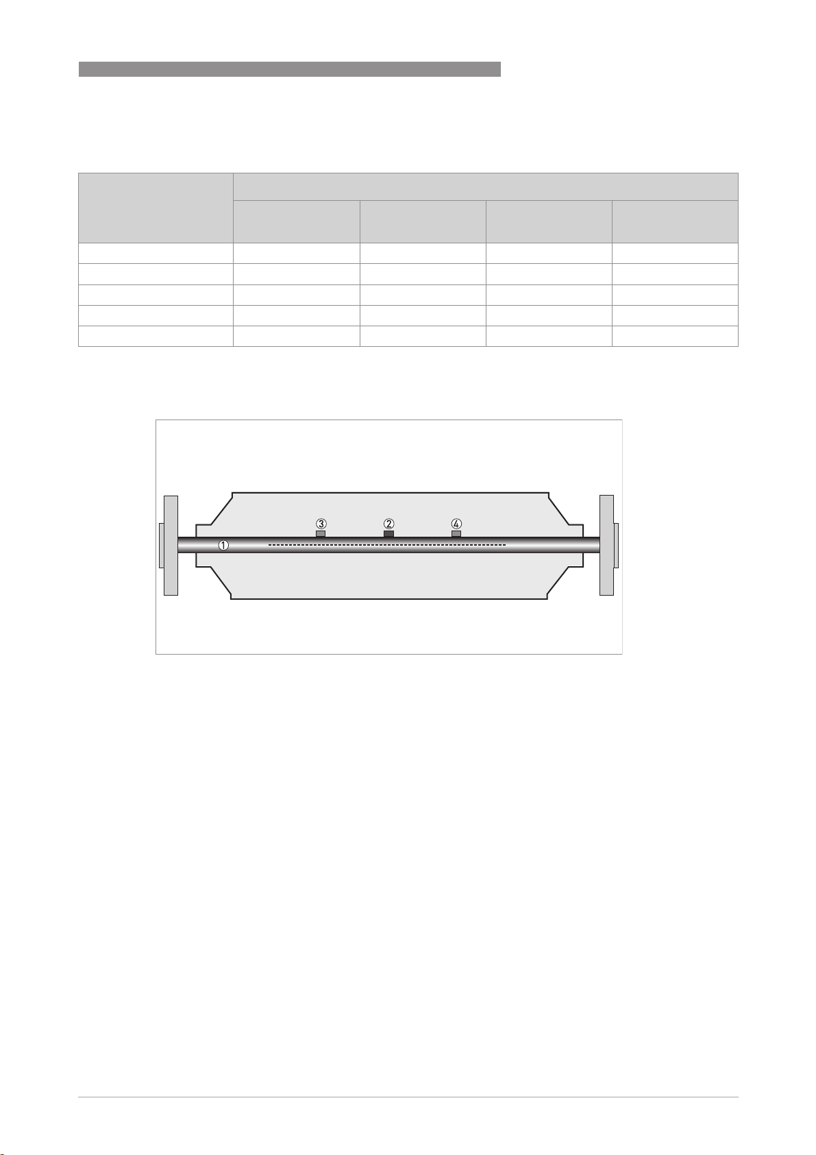
1.4 Measuring principle (single tube)
Static meter not energised and with no flow
1 Measuring tube
2 Drive coil
3 Sensor 1
4 Sensor 2
A Coriolis single tube mass flowmeter consists of a single measuring tube 1 a drive coil 2 and
two sensors (3 and 4) that are positioned either side of the drive coil.
www.krohne.com11/2009 - 4000498402 - TD MFC 300 R03 en
7
Page 8
1 PRODUCT FEATURES
Energised meter
1 Measuring tubes
2 Direction of oscilation
3 Sine wave
When the meter is energised, the drive coil vibrates the measuring tube causing it to oscillate
and produce a sine wave 3. The sine wave is monitored by the two sensors.
MFC 300
Energised meter with process flow
1 Process flow
2 Sine wave
3 Phase shift
When a fluid or gas passes through the tube, the coriolis effect causes a phase shift in the sine
wave that is detected by the two sensors. This phase shift is directly proportional to the mass
flow.
Density measurement is made by evaluation of the frequency of vibration and temperature
measurement is made using a Pt500 sensor.
8
www.krohne.com 11/2009 - 4000498402 - TD MFC 300 R03 en
Page 9

MFC 300
TECHNICAL DATA 2
2.1 Technical data
•
The following data is provided for general applications. If you require data that is more
relevant to your specific application, please contact us or your local representative.
•
Additional information (certificates, special tools, software,...) and complete product
documentation can be downloaded free of charge from the website (Download Center).
Measuring system
Measuring principle Coriolis principle
Application range Measurement of mass flow, density, temperature, volume flow, flow velocity,
Design
Modular construction The measuring system consists of a measuring sensor and a signal converter.
Measuring sensor
Measuring sensor
Measuring sensorMeasuring sensor
OPTIMASS 1000 DN15…50 / ½…2"
OPTIMASS 2000 DN100...250 / 4...10"
OPTIMASS 3000 DN01…04 / 1/25...4/25"
OPTIMASS 7000 DN06…80 / ¼…3"
OPTIMASS 8000 DN15…100 / ½…4"
Signal converter
Signal converter
Signal converterSignal converter
Compact version (C) OPTIMASS x300 C (x = 1, 2, 3, 7 or 8)
Field housing (F) remote version
Wall-mounted housing (W) remote version
19" rack-mounted housing (R) remote version
Options
Options
OptionsOptions
Outputs / inputs
Counters 2 (optional 3) internal counters with a max. of 8 counter places (e.g. for counting
Verification Integrated verification, diagnostic functions: measuring device, process, measured
Concentration measurement Concentration and concentration flow
Communication interfaces
concentration
All sensors are also available in Ex-versions.
MFC 300 F
MFC 300 W
MFC 300 R
Compact and field housing versions are also available in Ex versions.
Current- (incl. HART®), pulse, frequency, and/or status output, limit switch and/or
control input (depending on the I/O version)
volume and/or mass units)
value, stabilization
Foundation Fieldbus, Profibus PA and DP, Modbus, HART
®
www.krohne.com11/2009 - 4000498402 - TD MFC 300 R03 en
9
Page 10

2 TECHNICAL DATA
Display and user interface
Display and user interface
Display and user interfaceDisplay and user interface
Graphic display LC display, backlit white.
Size: 128 x 64 pixels, corresponds to 59 x 31 mm = 2.32" x 1.22"
Display can be turned in steps of 90°.
Ambient temperatures below -25°C / -13°F, may affect the readability of the display.
Operating elements 4 optical keys for operator control of the signal converter without opening the
Remote control
Display functions
Display functions
Display functionsDisplay functions
Operating menu Setting the parameters using 2 measured value pages, 1 status page, 1 graphics
Language display texts (as
language package)
Measurement functions Units:
Diagnostic functions Standards:
housing.
Infrared interface for reading and writing all parameters with IR interface (option)
without opening the housing.
PACTware® (incl. Device Type Manager (DTM))
HART® Hand Held Communicator from Emerson Process
AMS® from Emerson Process
PDM® from Siemens
All DTMs and drivers are available free of charge from the manufacturer's website.
page (measured values and graphics are freely adjustable)
Standard: English, French, German, Dutch, Portuguese, Swedish, Spanish, Italian
Eastern Europe (in preparation): English, Slovenian, Czech, Hungarian
Northern Europe (in preparation): English, Danish, Polish
China (in preparation): English, Chinese
Russia: English, Russian
Units: Metric, British and US units selectable as desired from lists for volume/mass
Units:Units:
flow and counting, velocity, temperature, pressure
Measured values:
Measured values: Mass flow, total mass, temperature, density, volume flow, total
Measured values:Measured values:
volume, velocity, flow direction (not displayed unit – but available via outputs), BRIX,
Baume, NaOH, Plato, API, mass concentration, volume concentration
Standards: according to VDI / NAMUR / WIB 2650 (pending) and functions going
Standards:Standards:
beyond that
Status messages:
Status messages: Output of status messages optional via display, current and/or
Status messages:Status messages:
status output, HART® or bus interface
Sensor diagnostics:
Sensor diagnostics: Sensor values, drive level, measuring tube frequency, MT
Sensor diagnostics:Sensor diagnostics:
(measuring tube) strain, IC (inner cylinder) strain, sensor electronics/board
electronics temperature, 2-phase flow signal
MFC 300
Measuring accuracy
Reference conditions Medium: water
Temperature: 20°C / 68°F
Pressure: 1 bar / 14.5 psi
Maximum measuring error ±0.10% of the measured value ± zero point stability (depending on the measuring
Repeatability ±0.05% ± zero point stability (depending on the measuring sensor)
10
sensor)
Current output electronics: ±5 µA
www.krohne.com 11/2009 - 4000498402 - TD MFC 300 R03 en
Page 11

MFC 300
TECHNICAL DATA 2
Operating conditions
Temperature
Temperature
TemperatureTemperature
Process temperature Refer to technical data for the measuring sensor.
Ambient temperature Depends on the version and combination of outputs.
It is a good idea to protect the converter from external heat sources such as direct
sunlight as higher temperatures reduce the life cycle of all electronic components.
-40…+65°C / -40…+149°F
Stainless Steel housing: -40…+55°C / -40…+131°F
Ambient temperatures below -25°C / -13°F, may affect the readability of the display.
Storage temperature -50…+70°C / -58…+158°F
Pressure
Pressure
PressurePressure
Medium Refer to technical data for the measuring sensor.
Ambient pressure Atmosphere
Chemical properties
Chemical properties
Chemical propertiesChemical properties
Physical condition Liquids, gases and slurries
Flow rate Refer to technical data for the measuring sensor.
Other conditions
Other conditions
Other conditionsOther conditions
Protection category acc. to
IEC 529 / EN 60529
C (compact version) & F (field housing):
IP66/67 (acc. to NEMA 4/4X)
W (wall-mounted housing):
IP 65 (acc. to NEMA 4/4x)
R (19" rack-mounted housing):
IP 20 (acc. to NEMA 1)
Installation conditions
Installation For detailed information, refer to chapter "Installation conditions".
Dimensions and weights For detailed information refer to chapter "Dimensions and weights".
www.krohne.com11/2009 - 4000498402 - TD MFC 300 R03 en
11
Page 12

2 TECHNICAL DATA
MFC 300
Materials
Signal converter housing Standard
Measuring sensor See the technical data for the measuring sensor for housing materials, process
Standard
StandardStandard
Version C and F: die-cast Aluminium (polyurethane-coated)
Version W: polyamide - polycarbonate
Version R: Aluminium, Stainless Steel and Aluminium sheet, partially polyestercoated
Option
Option
OptionOption
Versions C and F: Stainless Steel 316 L (1.4408)
connections, measuring tubes, accessories and gaskets.
Electrical connection
General Electrical connection is carried out in conformity with the VDE 0100 directive
Power supply Standard: 100…230 VAC (-15% / +10%), 50/60 Hz
Power consumption AC: 22 VA
Signal cable Only for remote versions.
Cable entries Standard: M20 x 1.5 (8...12 mm)
"Regulations for electrical power installations with line voltages up to 1000 V" or
equivalent national regulations.
Option 1: 24 VDC (-55% / +30%)
Option 2: 24 VAC/DC (AC: -15% / +10%, 50/60 Hz; DC: -25% / +30%)
DC: 12 W
4 core shielded cable. Detailed specifications available on request.
Length: max. 300 m / 1000 ft
Option: ½" NPT, PF ½
12
www.krohne.com 11/2009 - 4000498402 - TD MFC 300 R03 en
Page 13

MFC 300
TECHNICAL DATA 2
Inputs and outputs
General All outputs are electrically isolated from each other and from all other circuits.
All operating data and output values can be adjusted.
Description of used abbreviations U
Current output
Current output
Current outputCurrent output
Output data Volume flow, mass flow, temperature, density, flow velocity, diagnostic value, 2-
Temperature coefficient Typically ±30 ppm/K
Settings
Operating data Basic I/Os
Active U
= external voltage; RL = load + resistance;
ext
Uo = terminal voltage; I
= nominal current
nom
Safety limit values (Ex-i):
= max. input voltage; Ii = max. input current; Pi = max. input power rating;
U
i
Ci = max. input capacity; Li = max. input inductivity
phase signal
Concentration and concentration flow are also possible with available concentration
measurement (optional).
Without HART
Without HART
Without HARTWithout HART
®
Q = 0%: 0…20 mA; Q = 100%: 10…20 mA
Error identification: 3…22 mA
With HART
With HART
With HARTWith HART
®
Q = 0%: 4…20 mA; Q = 100%: 10…20 mA
Error identification: 3…22 mA
Basic I/Os Modular I/Os
Basic I/OsBasic I/Os
= 24 VDC
int, nom
Modular I/Os Ex i
Modular I/OsModular I/Os
Ex i
Ex iEx i
U
int, nom
= 20 VDC
Passive U
I ≤ 22 mA
RL ≤ 1kΩ
≤ 32 VDC
ext
I ≤ 22 mA
≤ 1.8 V
U
0
RL≤ (U
ext-U0
)/I
max
I ≤ 22 mA
RL ≤ 450 Ω
U0 = 21 V
=90mA
I
0
P0=0.5W
= 90 nF / L0 = 2 mH
C
0
C0=110nF/ L0=0.5mH
U
≤ 32 VDC
ext
I ≤ 22 mA
≤ 4 V
U
0
RL≤ (U
ext-U0
)/I
max
Ui= 30 V
= 100 mA
I
i
Pi=1W
=10nF
C
i
Li~0mH
www.krohne.com11/2009 - 4000498402 - TD MFC 300 R03 en
13
Page 14

2 TECHNICAL DATA
®
HART
HART
HARTHART
Description
HART® protocol via active and passive current output
MFC 300
HART® version: V5
Universal HART® parameter: completely integrated
Load
≥ 250 Ω at HART® test point;
Note maximum load for current output!
Multidrop operation Yes, current output = 4 mA
Multidrop address adjustable in operation menu 1…15
Device driver Available for FC 375, AMS, PDM, FDT/DTM
Registration (HART
Yes
Communication Foundation)
Pulse or frequency output
Pulse or frequency output
Pulse or frequency outputPulse or frequency output
Output data Pulse output: volume flow, mass flow, mass or volume of dissolved substance with
activated concentration measurement
Frequency output: flow velocity, mass flow, temperature, density, diagnostic value
Optional: concentration, flow of the dissolved substance
Function Adjustable as pulse or frequency output
Pulse rate/frequency 0.01...10000 pulses/s or Hz
Settings Mass or volume per pulse or max. frequency for 100% flow
Pulse width: setting automatic, symmetric or fixed (0.05...2000 ms)
Operating data Basic I/Os
Active - U
Basic I/Os Modular I/Os
Basic I/OsBasic I/Os
Modular I/Os Ex i
Modular I/OsModular I/Os
= 24 VDC -
nom
f
in operating menu set
max
Ex i
Ex iEx i
to
≤ 100 Hz:
f
max
I ≤ 20 mA
open:
I ≤ 0.05 mA
closed:
U
= 24 V
0, nom
at I=20mA
f
in operating menu set
max
to
100 Hz < f
≤ 10 kHz:
max
I ≤ 20 mA
open:
I ≤ 0.05 mA
closed:
U
= 22.5 V
0, nom
at I=1mA
= 21.5 V
U
0, nom
at I=10mA
U
= 19 V
0, nom
at I=20mA
14
www.krohne.com 11/2009 - 4000498402 - TD MFC 300 R03 en
Page 15

MFC 300
TECHNICAL DATA 2
Passive U
≤ 32 VDC -
ext
f
in operating menu set to
max
f
≤ 100 Hz:
max
I ≤ 100 mA
open:
I ≤ 0.05 mA at U
= 32 VDC
ext
closed:
U
= 0.2 V at I ≤ 10 mA
0, max
= 2 V at I ≤ 100 mA
U
0, max
f
in operating menu set to
max
100 Hz < f
≤ 10 kHz:
max
I ≤ 20 mA
open:
I ≤ 0.05 mA at U
=32VDC
ext
closed:
= 1.5 V at I ≤ 1mA
U
0, max
= 2.5 V at I ≤ 10 mA
U
0, max
U
= 5.0 V at I ≤ 20 mA
0, max
NAMUR - Passive to EN 60947-5-6
open:
I
=0.6mA
nom
closed:
=3.8mA
I
nom
Passive to EN 60947-5-6
open:
I
=0.43mA
nom
closed:
=4.5mA
I
nom
Ui= 30 V
Ii= 100 mA
=1W
P
i
Ci=10nF
~0mH
L
i
Low flow cut-off
Low flow cut-off
Low flow cut-offLow flow cut-off
Function Switching point and hysteresis separately adjustable for each output, counter and
the display
Switching point Set in increments of 0.1.
0…20% (current output, frequency output)
Hysteresis Set in increments of 0.1.
0…5% (current output, frequency output)
Time constant
Time constant
Time constantTime constant
Function The time constant corresponds to the elapsed time until 67% of the end value has
been reached according to a step function.
Settings Set in increments of 0.1.
0…100 s
www.krohne.com11/2009 - 4000498402 - TD MFC 300 R03 en
15
Page 16

2 TECHNICAL DATA
Status output / limit switch
Status output / limit switch
Status output / limit switchStatus output / limit switch
MFC 300
Function and settings Adjustable as automatic measuring range conversion, display of flow direction,
overflow, error, switching point
Valve control with activated dosing function
Status and/or control: ON or OFF
Operating data Basic I/Os
Active - U
Basic I/Os Modular I/Os
Basic I/OsBasic I/Os
Modular I/Os Ex i
Modular I/OsModular I/Os
= 24 VDC
int
Ex i
Ex iEx i
-
I ≤ 20 mA
open:
I ≤ 0.05 mA
closed:
U
= 24 V
0, nom
at I=20mA
Passive U
≤ 32 VDC
ext
U
ext
= 32 VDC
-
I ≤ 100 mA
open:
I ≤ 0.05 mA at
=32VDC
U
ext
closed:
U
= 0.2 V
0, max
at I ≤ 10 mA
= 2 V
U
0, max
at I ≤ 100 mA
I ≤ 100 mA
= 47 kΩ
R
L, max
R
=(U
L, min
open:
I ≤ 0.05 mA
at U
=32VDC
ext
closed:
U
= 0.2 V
0, max
ext-U0
)/I
max
at I ≤ 10 mA
= 2 V
U
0, max
at I ≤ 100 mA
NAMUR - Passive to EN 60947-5-6
open:
I
=0.6mA
nom
closed:
I
=3.8mA
nom
Passive to EN 60947-5-6
open:
I
=0.43mA
nom
closed:
I
=4.5mA
nom
Ui= 30 V
= 100 mA
I
i
Pi=1W
=10nF
C
i
Li = 0 mH
16
www.krohne.com 11/2009 - 4000498402 - TD MFC 300 R03 en
Page 17

MFC 300
Control input
Control input
Control inputControl input
TECHNICAL DATA 2
Function Hold output values (e.g. when cleaning), set value of outputs to "zero", counter and
error reset, hold counter, range conversion, zero point calibration.
Start of dosing when dosing function is activated.
Operating data Basic I/Os
Active - U
Basic I/Os Modular I/Os
Basic I/OsBasic I/Os
Modular I/Os Ex i
Modular I/OsModular I/Os
= 24 VDC
int
Ex i
Ex iEx i
-
Ext. contact open:
= 22 V
U
0, nom
Ext. contact closed:
I
= 4 mA
nom
Contact closed (on):
≥ 12 V
U
0
with I
nom
=1.9mA
Contact open (off):
≤ 10 V
U
0
Passive 8V≤ U
≤ 32 VDC
ext
with I
3V≤ U
nom
ext
=1.9mA
≤ 32 VDC
U
ext
≤ 32 VDC
= 6.5 mA
I
max
at U
≤ 24 VDC
ext
= 8.2 mA
I
max
at U
≤ 32 VDC
ext
Contact closed (on):
≥ 8 V
U
0
with I
= 2.8 mA
nom
Contact open (off):
≤ 2.5 V
U
0
with I
= 0.4 mA
nom
= 9.5 mA
I
max
at U
≤ 24 V
ext
= 9.5 mA
I
max
at U
≤ 32 V
ext
Contact closed (on):
≥ 3 V
U
0
with I
nom
=1.9mA
Contact open (off):
≤ 2.5 V
U
0
with I
nom
=1.9mA
NAMUR - Active to EN 60947-5-6
Terminals open:
U
= 8.7 V
0, nom
Contact closed (on):
= 6.3 V
U
0, nom
with I
> 1.9 mA
nom
Contact open (off):
= 6.3 V
U
0, nom
with I
< 1.9 mA
nom
Detection of cable break:
≥ 8.1 V
U
0
with I ≤ 0.1 mA
I ≤ 6 mA at U
I ≤ 6.6 mA at U
ext
=24V
=32V
ext
On:
≥ 5.5 V or I ≥ 4mA
U
0
Off:
U0 ≤ 3.5 V or I ≤ 0.5 mA
Ui= 30 V
= 100 mA
I
i
Pi=1W
= 10 nF
C
i
Li = 0 mH
-
Detection of cable short
circuit:
U0 ≤ 1.2 V
with I ≥ 6.7 mA
www.krohne.com11/2009 - 4000498402 - TD MFC 300 R03 en
17
Page 18

2 TECHNICAL DATA
PROFIBUS DP
PROFIBUS DP
PROFIBUS DPPROFIBUS DP
Description Galvanically isolated acc. to IEC 61158
Profile version: 3.01
Automatic data transmission rate recognition (max. 12 MBaud)
Bus address adjustable via local display at the measuring device
Function blocks 8 x analogue input, 3 x totaliser
Output data Mass flow, volume flow, mass counter 1 + 2, volume counter, product temperature,
PROFIBUS PA
PROFIBUS PA
PROFIBUS PAPROFIBUS PA
Description Galvanically isolated acc. to IEC 61158
Function blocks 8 x analogue input, 3 x totaliser
Output data Mass flow, volume flow, mass counter 1 + 2, volume counter, product temperature,
FOUNDATION Fieldbus
FOUNDATION Fieldbus
FOUNDATION FieldbusFOUNDATION Fieldbus
Description Galvanically isolated acc. to IEC 61158
Function blocks 6 x analogue Input, 3 x integrator, 1 x PID
Output data Mass flow, volume flow, density, temperature of tube, several concentration
Modbus
Modbus
ModbusModbus
Description Modbus RTU, Master / Slave, RS485
Address range 1…247
Supported function codes 01, 03, 04, 05, 08, 16
Broadcast Supported with function code 16
Supported Baudrate 1200, 2400, 4800, 9600, 19200, 38400, 57600, 115200 Baud
several concentration measurements and diagnostic data
Profile version: 3.01
Current consumption: 10.5 mA
Permissible bus voltage: 9…32 V; in Ex application: 9...24 V
Bus interface with integrated reverse polarity protection
Typical error current FDE (Fault Disconnection Electronic): 4.3 mA
Bus address adjustable via local display at the measuring device
several concentration measurements and diagnostic data
Current consumption: 10.5 mA
Permissible bus voltage: 9…32 V; in Ex application: 9...24 V
Bus interface with integrated reverse polarity protection
Link Master function (LM) supported
Tested with Interoperable Test Kit (ITK) version 5.1
measurements and diagnostic data
MFC 300
18
www.krohne.com 11/2009 - 4000498402 - TD MFC 300 R03 en
Page 19

MFC 300
TECHNICAL DATA 2
Approvals and certificates
CE The device fulfils the statutory requirements of the EC directives. The manufacturer
Non-Ex Standard
Hazardous areas
Hazardous areas
Hazardous areasHazardous areas
Option (only version C)
Option (only version C)
Option (only version C)Option (only version C)
ATEX II 2 G Ex d [ib] IIC T6....T1
Option (only version F)
Option (only version F)
Option (only version F)Option (only version F)
ATEX II 2 G Ex d [ib] IIC T6
Nepsi Ex de ib [ia/ib] IIC T6
Optional (only versions C and F)
Optional (only versions C and F)
Optional (only versions C and F)Optional (only versions C and F)
FM / CSA Class I, Div 1 groups B, C, D
IECEx (pending) Ex zone 1 + 2
TIIS (in preparation) Zone 1/2
Custody transfer
Custody transfer
Custody transferCustody transfer
Without Standard
Option Liquids other than water 2004/22/EC (MID) acc. to OIML R 117-1
Other standards and approvals
Other standards and approvals
Other standards and approvalsOther standards and approvals
Shock and vibration resistance IEC 68-2-3
Electromagnetic compatibility
(EMC)
European Pressure Equipment
Directive
NAMUR NE 21, NE 43, NE 53
certifies that these requirements have been met by applying the CE marking.
II 2 G Ex de [ib] IIC T6....T1
II 2 D Ex tD A21 IP6x T160°C (dep. on the measuring sensor)
without heating jacket or sensor insulation
II 2 D Ex tD A21 IP6x T170°C (dep. on the measuring sensor)
with heating jacket and sensor insulation
II 2(1) G Ex d [ia/ib] IIC T6....T1
II 2(1) G Ex de [ia/ib] IIC T6....T1
II 2(1) D Ex tD [iaD] A21 IP6x T160°C (dep. on the measuring sensor)
without heating jacket or sensor insulation
II 2(1) D Ex tD [iaD] A21 IP6x T170°C (dep. on the measuring sensor)
with heating jacket and sensor insulation
II 2 G Ex de [ib] IIC T6
II 2(1) G Ex d [ia/ib] IIC T6
II 2(1) G Ex de [ia/ib] IIC T6
II 2 D Ex tD [ibD] A21 IP6x T80°C
II 2(1) G Ex tD [iaD/ibD] A21 IP6x T80°C
Ex d ib [ia/ib] IIC T6
Class II, Div 1 groups E, F, G
Class III, Div 1 hazardous areas
Class I, Div 2 groups B, C, D
Class II, Div 2 groups F, G
Class III, Div 2 hazardous areas
2004/108/EC in conjunction with EN 61326-1 (A1, A2)
PED 97/23 (only for compact versions)
www.krohne.com11/2009 - 4000498402 - TD MFC 300 R03 en
19
Page 20

2 TECHNICAL DATA
2.2 Dimensions and weights
2.2.1 Housing
MFC 300
1 Compact version (C)
2 Field housing (F) - remote version
3 Wall-mounted housing (W) - remote version
4 19" rack-mounted housing (R) - remote version
Dimensions and weights in mm and kg
Version Dimensions [mm] Weight [kg]
a b c d e g h
C 202 120 155 260 137 - - 4.2
F 202 120 155 - - 295.8 277 5.7
W 198 138 299 - - - - 2.4
R 142
(28 TE)
129
(3 HE)
195 - - - - 1.2
Dimensions and weights in inches and lb
Version Dimensions [inches] Weight [lb]
a b c d e g h
C 7.75 4.75 6.10 10.20 5.40 - - 9.30
F 7.75 4.75 6.10 - - 11.60 10.90 12.60
W 7.80 5.40 11.80 - - - - 5.30
R 5.59
(28 TE)
5.08
(3 HE)
7.68 - - - - 2.65
20
www.krohne.com 11/2009 - 4000498402 - TD MFC 300 R03 en
Page 21

MFC 300
2.2.2 Mounting plate, field housing
Dimensions in mm and inches
a 60 2.4
b 100 3.9
c Ø9 Ø0.4
TECHNICAL DATA 2
[mm] [inches]
2.2.3 Mounting plate, wall-mounted housing
Dimensions in mm and inches
a Ø9 Ø0.4
b 64 2.5
c 16 0.6
d 6 0.2
e 63 2.5
f 4 0.2
g 64 2.5
h 98 3.85
[mm] [inches]
www.krohne.com11/2009 - 4000498402 - TD MFC 300 R03 en
21
Page 22

3 INSTALLATION
3.1 Intended use
The mass flowmeters are designed exclusively to directly measure mass flow rates, product
density and temperature as well to indirectly measure parameters such as the total volume and
concentration of dissolved substances as well as the volume flow rate.
For devices used in hazardous areas, additional safety notes apply; please refer to the Ex
documentation.
3.2 Installation specifications
The following precautions must be taken to ensure reliable installation.
•
Make sure that there is adequate space to the sides.
•
Protect the signal converter from direct sunlight and install a sun shade if necessary.
•
Signal converters installed in control cabinets require adequate cooling, e.g. by fan or heat
exchanger.
•
Do not expose the signal converter to intense vibration. The flowmeters are tested for a
vibration level in accordance with IEC 68-2-3.
MFC 300
3.3 Mounting of the compact version
The signal converter is mounted directly on the measuring sensor. For installation of the
flowmeter, please observe the instructions in the supplied product documentation for the
measuring sensor.
3.4 Mounting the field housing, remote version
Assembly materials and tools are not part of the delivery. Use the assembly materials and tools
in compliance with the applicable occupational health and safety directives.
3.4.1 Pipe mounting
22
Figure 3-1: Pipe mounting of the field housing
1 Fix the signal converter to the pipe.
2 Fasten the signal converter using standard U-bolts and washers.
3 Tighten the nuts.
www.krohne.com 11/2009 - 4000498402 - TD MFC 300 R03 en
Page 23

MFC 300
3.4.2 Wall mounting
Figure 3-2: Wall mounting of the field housing
INSTALLATION 3
1 Prepare the holes with the aid of the mounting plate. For further information refer to
plate, field housing
on page 21.
Mounting
2 Use the mounting material and tools in compliance with the applicable occupational health
and safety directives.
3 Fasten the housing securely to the wall.
Mounting multiple devices next to each other
a ≥ 600 mm / 23.6"
b ≥ 250 mm / 9.8"
www.krohne.com11/2009 - 4000498402 - TD MFC 300 R03 en
23
Page 24

3 INSTALLATION
3.5 Mounting the wall-mounted housing, remote version
Assembly materials and tools are not part of the delivery. Use the assembly materials and tools
in compliance with the applicable occupational health and safety directives.
3.5.1 Pipe mounting
MFC 300
Figure 3-3: Pipe mounting of the wall-mounted housing
1 Fasten the mounting plate to the pipe with standard U-bolts, washers and fastening nuts.
2 Screw the signal converter to the mounting plate with the nuts and washers.
24
www.krohne.com 11/2009 - 4000498402 - TD MFC 300 R03 en
Page 25

MFC 300
3.5.2 Wall mounting
Figure 3-4: Wall mounting of the wall-mounted housing
INSTALLATION 3
1 Prepare the holes with the aid of the mounting plate. For further information refer to
plate, wall-mounted housing
2 Fasten the mounting plate securely to the wall.
3 Screw the signal converter to the mounting plate with the nuts and washers.
on page 21.
Mounting multiple devices next to each other
a ≥ 240 mm / 9.4"
Mounting
www.krohne.com11/2009 - 4000498402 - TD MFC 300 R03 en
25
Page 26

4 ELECTRICAL CONNECTIONS
4.1 Important notes on electrical connection
Electrical connection is carried out in conformity with the VDE 0100 directive "Regulations for
electrical power installations with line voltages up to 1000 V" or equivalent national regulations.
•
Use suitable cable entries for the various electrical cables.
•
The sensor and converter are configured together in the factory. For this reason, please
connect the devices in pairs.
4.2 Connection diagram
The device must be grounded in accordance with regulations in order to protect personnel
against electric shocks.
MFC 300
26
Figure 4-1: Connection diagram for remote versions, wall, field and 19" rack-mounted version
1 Terminal compartment for signal converter
2 Terminal compartment for measuring sensor
3 Connect shielding to spring terminal
4 Connect shielding to terminal S
(with 19" rack-mounted housing, the shielding can be connected to 22z, 22d, 24z or 24d)
5 Functional ground
www.krohne.com 11/2009 - 4000498402 - TD MFC 300 R03 en
Page 27

MFC 300
ELECTRICAL CONNECTIONS 4
4.3 Connecting power, all housing variants
The device must be grounded in accordance with regulations in order to protect personnel
against electric shocks.
For devices used in hazardous areas, additional safety notes apply; please refer to the Ex
documentation.
• The protection category depends on the housing versions (IP65...67 to IEC 529 / EN 60529 or
NEMA4/4X/6).
• The housings of the devices, which are designed to protect the electronic equipment from
dust and moisture, should be kept well closed at all times. Creepage distances and
clearances are dimensioned to VDE 0110 and IEC 664 for pollution severity 2. Supply circuits
are designed for overvoltage category III and the output circuits for overvoltage category II.
• Fuse protection (I
(switch, circuit breaker) to isolate the signal converter must be provided.
Power supply connection (excluding 19" rack-mounted housing)
≤ 16 A) for the infeed power circuit, and also a disconnecting device
N
1 100...230 VAC (-15% / +10%)
2 24 VDC (-55% / +30%)
3 24 VAC/DC (AC: -15% / +10%; DC: -25% / +30%)
www.krohne.com11/2009 - 4000498402 - TD MFC 300 R03 en
27
Page 28

4 ELECTRICAL CONNECTIONS
100...230 VAC (tolerance range: -15% / +10%)
• Note the power supply voltage and frequency (50...60 Hz) on the nameplate.
• The protective ground terminal PE
clamp terminal in the terminal compartment of the signal converter
240 VAC+5% is included in the tolerance range.
24 VDC (tolerance range: -55% / +30%)
24 VAC/DC (tolerance ranges: AC: -15% / +10%; DC: -25% / +30%)
• Note the data on the nameplate!
• For measurement process reasons, a functional ground FE
separate U-clamp terminal in the terminal compartment of the signal converter.
• When connecting to functional extra-low voltages, provide a facility for protective separation
(PELV) (as per VDE 0100 / VDE 0106 and IEC 364 / IEC 536 or relevant national regulations).
For 24 VDC, 12 VDC-10% is included in the tolerance range.
PE of the power supply must be connected to the separate U-
PEPE
FE must be connected to the
FEFE
MFC 300
Power supply connection for 19" rack-mounted housing
28
www.krohne.com 11/2009 - 4000498402 - TD MFC 300 R03 en
Page 29

MFC 300
4.4 Inputs and outputs, overview
4.4.1 Combinations of the inputs/outputs (I/Os)
This signal converter is available with various in-/output combinations.
Basic version
• Has 1 current, 1 pulse and 2 status outputs / limit switches.
• The pulse output can be set as status output/limit switch and one of the status outputs as a
control input.
Ex i version
• Depending on the task, the device can be configured with various output modules.
• Current outputs can be active or passive.
• Optionally available also with Foundation Fieldbus and Profibus PA
Modular version
• Depending on the task, the device can be configured with various output modules.
ELECTRICAL CONNECTIONS 4
Bus systems
• The device allows intrinsically safe and non intrinsically safe bus interfaces in combination
with additional modules.
• For connection and operation of bus systems, please note the separate documentation.
Ex option
• For hazardous areas, all of the input/output variants for the housing designs C and F with
terminal compartment in the Ex-d (pressure-resistant casing) or Ex-e (increased safety)
versions can be delivered.
• Please refer to the separate instructions for connection and operation of the Ex-devices.
www.krohne.com11/2009 - 4000498402 - TD MFC 300 R03 en
29
Page 30

4 ELECTRICAL CONNECTIONS
4.4.2 Description of the CG number
Figure 4-2: Marking (CG number) of the electronics module and input/output variants
1 ID number: 2
2 ID number: 0 = standard; 9 = special
3 Power supply option
4 Display (language versions)
5 Input/output version (I/O)
6 1st optional module for connection terminal A
7 2nd optional module for connection terminal B
The last 3 digits of the CG number (5, 6 und 7) indicate the assignment of the terminal
connections. Please see the following examples.
Examples for CG number
MFC 300
CG 320 11 100 100...230 VAC & standard display; basic I/O: Ia or Ip & Sp/Cp & Sp & Pp/S
p
CG 320 11 7FK 100...230 VAC & standard display; modular I/O: Ia & PN/SN and optional module PN/SN & C
CG 320 81 4EB 24 VDC & standard display; modular I/O: Ia & Pa/Sa and optional module Pp/Sp & I
p
Description of abbreviations and CG identifier for possible optional modules
on terminals A and B
Abbreviation Identifier for CG No. Description
I
a
I
p
Pa / S
a
Pp / S
p
PN / S
N
C
a
C
p
C
N
IIn
a
IIn
p
- 8 No additional module installed
- 0 No further module possible
A Active current output
B Passive current output
C Active pulse, frequency, status output or limit switch (changeable)
E Passive pulse, frequency, status output or limit switch (changeable)
F Passive pulse, frequency, status output or limit switch according to
NAMUR (changeable)
G Active control input
K Passive control input
H Active control input to NAMUR
Signal converter monitors cable breaks and short circuits acc. to
EN 60947-5-6. Errors indicated on LC display. Error messages possible
via status output.
P Active current input
R Passive current input
N
30
www.krohne.com 11/2009 - 4000498402 - TD MFC 300 R03 en
Page 31

MFC 300
4.4.3 Fixed, non-alterable input/output versions
This signal converter is available with various in-/output combinations.
• The grey boxes in the tables denote unassigned or unused connection terminals.
• In the table, only the final digits of the CG-No. are depicted.
• Connection terminal A+ is only operable in the basic input/output version.
CG-No. Connection terminals
A+ A A- B B- C C- D D-
Basic in-/output (I/O) (Standard)
1 0 0
Ia + HART® active 1
Ip + HART® passive 1
Ex-i inputs/outputs (optional)
2 0 0
3 0 0
2 1 0 Ia active PN / SNNAMUR
3 1 0 Ia active PN / SNNAMUR
2 2 0 Ip passive PN / SNNAMUR
3 2 0 Ip passive PN / SNNAMUR
Sp / Cp passive 2 Sp passive Pp / Sp passive 2
passive 2
C
p
Cp passive 2
passive 2
C
p
Cp passive 2
ELECTRICAL CONNECTIONS 4
Ia + HART® active
Ip + HART® passive
Ia + HART® active
Ip + HART® passive
Ia + HART® active
Ip + HART® passive
PN / SN NAMUR 2
PN / SN NAMUR 2
PN / SN NAMUR 2
PN / SN NAMUR 2
PN / SNNAMUR 2
PN / SNNAMUR 2
PROFIBUS PA (Ex-i) (Option)
D 0 0 PA+ PA- PA+ PA-
FISCO Device FISCO Device
D 1 0 Ia active PN / SNNAMUR
passive 2
C
p
D 2 0 Ip passive PN / SNNAMUR
passive 2
C
p
PA+ PA- PA+ PA-
FISCO Device FISCO Device
PA+ PA- PA+ PA-
FISCO Device FISCO Device
www.krohne.com11/2009 - 4000498402 - TD MFC 300 R03 en
31
Page 32

4 ELECTRICAL CONNECTIONS
FOUNDATION Fieldbus (Ex-i) (Option)
E 0 0 V/D+ V/D- V/D+ V/D-
FISCO Device FISCO Device
E 1 0 Ia active PN / SNNAMUR
Cp passive 2
E 2 0 Ip passive PN / SNNAMUR
Cp passive 2
1 function changed by reconnecting
2 changeable
V/D+ V/D- V/D+ V/D-
FISCO Device FISCO Device
V/D+ V/D- V/D+ V/D-
FISCO Device FISCO Device
MFC 300
32
www.krohne.com 11/2009 - 4000498402 - TD MFC 300 R03 en
Page 33

MFC 300
4.4.4 Alterable input/output versions
This signal converter is available with various in-/output combinations.
• The grey boxes in the tables denote unassigned or unused connection terminals.
• In the table, only the final digits of the CG-No. are depicted.
• Term. = (connection) terminal
CG-No. Connection terminals
A+ A A- B B- C C- D D-
Modular inputs/outputs (option)
4 _ _ max. 2 optional modules for term. A + B
8 _ _ max. 2 optional modules for term. A + B
6 _ _ max. 2 optional modules for term. A + B
B _ _ max. 2 optional modules for term. A + B
7 _ _ max. 2 optional modules for term. A + B
C _ _ max. 2 optional modules for term. A + B
ELECTRICAL CONNECTIONS 4
Ia + HART® active
Ip + HART® passive
Ia + HART® active
Ip + HART® passive
Ia + HART® active
Ip + HART® passive
Pa / Sa active 1
Pa / Sa active 1
Pp / Sp passive 1
Pp / Sp passive 1
PN / SN NAMUR 1
PN / SN NAMUR 1
PROFIBUS PA (Option)
D _ _ max. 2 optional modules for term. A + B PA+ (2) PA- (2) PA+ (1) PA- (1)
FOUNDATION Fieldbus (Option)
E max. 2 optional modules for term. A + B V/D+ (2) V/D- (2) V/D+ (1) V/D- (1)
PROFIBUS DP (Option)
F _ 0 1 optional module for
term. A
Termination P
RxD/TxDP(2)
RxD/TxDN(2)
Termination N
RxD/TxDP(1)
RxD/TxDN(1)
Modbus (Option)
G _ _ 2 max. 2 optional modules for term. A + B Common Sign. B
(D1)
H _ _ 3 max. 2 optional modules for term. A + B Common Sign. B
(D1)
1 changeable
2 not activated bus terminator
3 activated bus terminator
Sign. A
(D0)
Sign. A
(D0)
www.krohne.com11/2009 - 4000498402 - TD MFC 300 R03 en
33
Page 34

4 ELECTRICAL CONNECTIONS
4.5 Laying electrical cables correctly
Figure 4-3: Protect housing from dust and water
1 Lay the cable in a loop just before the housing.
2 Tighten the screw connection of the cable entry securely.
3 Never mount the housing with the cable entries facing upwards.
4 Seal cable entries that are not needed with a plug.
MFC 300
34
www.krohne.com 11/2009 - 4000498402 - TD MFC 300 R03 en
Page 35

MFC 300
NOTES 5
www.krohne.com11/2009 - 4000498402 - TD MFC 300 R03 en
35
Page 36

K
K
K
KROHNE product overview
• Electromagnetic flowmeters
• Variable area flowmeters
• Ultrasonic flowmeters
• Mass flowmeters
• Vortex flowmeters
• Flow controllers
• Level meters
• Temperature meters
• Pressure meters
• Analysis products
• Measuring systems for the oil and gas industry
• Measuring systems for sea-going tankers
© KROHNE 11/2009 - 4000498402 - TD MFC 300 R03 en - Subject to change without notice.
Head Office KROHNE Messtechnik GmbH
Ludwig-Krohne-Str. 5
D-47058 Duisburg (Germany)
Tel.:+49 (0)203 301 0
Fax:+49 (0)203 301 10389
info@krohne.de
The current list of all KROHNE contacts and addresses can be found at:
www.krohne.com
 Loading...