

Page 1
Page 2

General advice on safety
Use of MagCheck on converters, which are not listed as may cause damage to these converters, to
MagCheck and, in case of connection to hazardous area versions of these converters damage to
protective elements. As a result safety risks in later operation of these converters cannot be
excluded.
Product liability and warranty
Responsibility for suitability and intended use of this instrument rests solely with the user. Improper
installation and operation may lead to loss of warranty. In addition, the general conditions of sale
are applicable and are the basis for the purchase contract.
If the instrument needs to be returned to KROHNE, please note the information given in the service
part of these instructions.
Items included with supply
A rugged suitcase containing:
• MagCheck
• Operating and installation instructions (hard copy)
• CD with MagCheck PC program, operating and installation instructions, Excel spreadsheets for
data processing
• IFC 010 connecting cable
• IFC 020 connecting cable
• IFC 090 connecting cable
• IFC 110 connecting cable
• PC RS 232 connecting cable
• Power supply adapter 100..230V to 15 V DC
• Power plug adapter for different plug standards
2 MagCheck
Page 3

Table of contents
General advice on safety 3
Product liability and warranty 3
Items included with supply 3
1 MagCheck introduction 4
1.1 Introduction 4
1.2 MagCheck as automatic verificator for KROHNE IMoCom converters 4
1.3 MagCheck as manual signal calibrator 5
2 Connecting and operating MagCheck 6
2.1 Preparation 6
2.2 Connecting cables 6
2.3 Connection diagrams 7
2.4 User interfaces 9
2.5 Starting phase 9
2.6 How to operate the menu 10
3 Description of MagCheck menu functions 12
3.1 Menu structure 12
3.2 Automatic verification with KROHNE IMoCom converters 13
3.3 MagCheck as manual flow signal calibrator 14
3.4 MagCheck Menu functions for manual calibration test 17
4 Using MagCheck with a PC 21
4.1 System specifications 21
4.2 Installation PC software 21
4.3 Settings of MagCheck PC software 21
4.4 Connecting MagCheck to PC 22
4.5 Downloading and storing MagCheck verification data onto PC 22
4.6 Exporting and importing verification files from / to floppy or hard disk 23
4.7 Trend analysis 24
5 Interpretation of verification results 26
5.1 Accuracy data ADC, field current, mA or frequency output 26
5.2 Coil resistance 26
5.3 Electrode resistance with full pipe 26
5.4 Electrode resistance with empty pipe 27
5.5 Coil insulation 28
5.6 Limitations of accuracy statement 28
6 Service and recalibration 29
6.1 Recalibration 29
6.2 Software 29
6.3 Spare parts 29
Appendix 1 29
MagCheck 3
Page 4
1 MagCheck introduction
1.1 Introduction
MagCheck is an all-round portable testing and verification device for KROHNE electromagnetic
flowmeters, enabling a complete functionality and accuracy verification of the EMF without taking
the meter out of the pipeline nor interrupting the process. MagCheck measures autonomously and
can be used on KROHNE EMF-converters (not on Ex-converters!). MagCheck can be employed
either as an automatic verification instrument or as a manual flow signal calibrator, depending on
the converter type.
MagCheck is used for precise analysis and verification of magnetic flowmeters. Precision of these
meters is not only a function of accuracy of electric data, but also depends on the mechanical
installation of flowhead and converter. Faulty installation, both mechanical or electrical, may not be
detected by MagCheck.
Use of MagCheck on converters, which are not listed as compatible may cause
damage to these converters, to MagCheck and in case of connection to hazardous
area versions of these converters damage to protective elements!
MagCheck can and must NOT be used on:
• TIV 50, TIV 60
• K300, F200
• SC150
• ALTOFLUX 2W, IFC 040
• IFC 090i
• TIDALFLUX*
• CAPAFLUX, IFC 090 K / CAP
• NB 900 Power Booster
• Any Ex Zone 1/div 1 versions (hazardous area versions) of
ALTOFLUX 2W, IFC 040; SC80A / AS, SC100A / AS;
IFC 080, IFC 200, IFC 200 E; IFC 090, IFC 090i; IFC 110;
IFC 210 Ex versions!
*) Verification of the conventional electromagnetic flowmeter part of TIDALFLUX IFM 4110 PF is
possible after disabling the level input to IFC 110 PF. This will allow for a statement of flow velocity
measurement part, not of total the performance of TIDALFLUX.
1.2 MagCheck as automatic verificator for KROHNE IMoCom converters
MagCheck is able to perform a fully automatic verification on magnetic flowmeters in combination
with these converters. In this mode accuracy of the converter and all electric data of the primary
head are verified which are vital for their function and accuracy. During the fully automatic test run
the display will indicate all measured data. MagCheck reads and stores all settings of the IMoCom
converter and all measured data of up to 70 meters.
MagCheck can verify KROHNE electromagnetic flowmeters with following IMoCom signal
converters:
• IFC 010
• IFC 020
• IFC 090 Non-Ex versions
Data may be downloaded onto a PC (Microsoft Windows 95, 98, 2000, NT) using the KROHNE
MagCheck PC-program. After downloading data into the PC the related memory areas in the
MagCheck are cleared and can be used for further measurements. The KROHNE MagCheck PCprogram evaluates the downloaded data. If all data are within their limits, the program will create a
final certificate confirming the meter operates with an accuracy deviation of less then 1% related to
reference conditions. If the evaluation shows data exceeding their limits, the certificate will state,
that the meter is not working properly.
• IFC 110 Non-Ex and non TIDALFLUX-versions only
• IFC 210 Non-Ex versions
4 MagCheck
Page 5

1.3 MagCheck as manual signal calibrator
MagCheck replaces KROHNE Simulators GS8 / GS8A. With its integrated microprocessor,
calibrated mA-meter and frequency meter MagCheck allows for verifying the accuracy of converters
without the need for any further instruments like calculators, mA- and frequency meters.
MagCheck generates precise adjustable flow signals. The flow signal can be set in steps of 0.1% of
full scale. These very precise flow signals will be fed into the signal inputs of the converter. The
output signals (mA, frequency) are indicated on the MagCheck display. In this manual flow signal
calibrator mode no data will be stored in MagCheck. The measured/indicated data must be noted
and evaluated manually (see Appendix 1).
With non-IMoCom converters: In the flow signal calibrator mode with these previous converters data
as meter size (DN), GK, full scale setting must be entered into MagCheck manually.
MagCheck may be used
as flow signal calibrator for
following KROHNE
electromagnetic flowmeter
signal converters:
With IMoCom converters MagCheck loads data as meter size (DN), GK, full scale setting, current
and pulse output settings automatically down from IMoCom converter through the IMoCom
interface.
• T900
• SC100A, SC 100AS Non-Ex versions only!
• SC80A, SC 80AS Non-Ex versions only!
• AQUAFLUX 070
• IFC 080 Non-Ex versions only!
• IFC 200E, IFC 200. Non-Ex versions only!
• and all IMoCom converters as listed under 1.2
MagCheck 5
Page 6
2 Connecting and operating MagCheck
2.1 Preparation
2.1.1 Initial preparations
Make sure that there is sufficient memory space left for new verifications. Connect MagCheck to a
power outlet via its power adapter. MagCheck will start searching for the IMoCom interface. Stop
this by pressing F1. Enter Menu 1.1. test MID. Press arrow →. MagCheck will indicate (example):
1.1 test MID
no connection
inputs: 69/70
In this case only one set of data (one verification) can be stored additionally. Download existing
data into the PC to clear more memory space (refer to chapter 5) if necessary. Take print-outs of
the Excel spreadsheets (Refer to Appendix 1) and results of earlier verifications/ tests on related
meters with you.
2.1.2 Document flowmeter data
Read and note all totalisers and counter values before and after verification and document the
following (you may note these in the dedicated Excel spreadsheets, refer to chapter 7):
2.1.3 Disconnecting cables
Prior to connecting MagCheck to the magnetic flowmeter, signal-, field-, output cables of the
flowmeter must be disconnected by pulling the connectors. All flowmeter outputs are interrupted,
related process instrumentation will see open inputs. As a result the meter will not indicate the
actual flow during the verification the meter.
Before changing any connections act according all process related safety and
information rules existing in your organisation! Disable all alarms and take all
controls to manual, which are dependent on the flowmeter outputs!
2.2 Connecting cables
MagCheck is supplied with connection cables for IFC 010, IFC 020, IFC 090, IFC 110 F and a
RS 232 cable (25 pole to 9 pole connector) for connecting MagCheck to PC (download of
verification data) and a 100..230 Volt AC power supply, that is only used during download of
verification data from MagCheck into PC. There is no need to unscrew any terminal screw with
these cables. For manual calibration tests on older Non-IMoCom converters special cables can be
supplied on request.
The 25-pin connector must be plugged into the MagCheck. Its securing screws must be fid to avoid
contact failures during verification runs, e.g. due to accidental mechanical stress on the cable (see
connection diagrams)
The following connections to the signal converter must be established:
• IMoCom (for tests on IMoCom converters only as listed under 1.2.)
• Electrode signal
• Field current
• Outputs (mA and pulse)
Connection to flow head (flow tube) only is necessary for automatic verification with IMoCom
converters, not for use of MagCheck as precision flow signal calibrator for converter verifications.
The following connections to the flow head must be established±
• Electrode signal
• Field coil connection
6 MagCheck
Page 7
During verification and test of converters as listed above, MagCheck does not need
any external power supply or batteries. MagCheck takes all its power from the field
current of these signal converters. The external power supply supplied with
MagCheck is only needed during download of verification data into a PC.
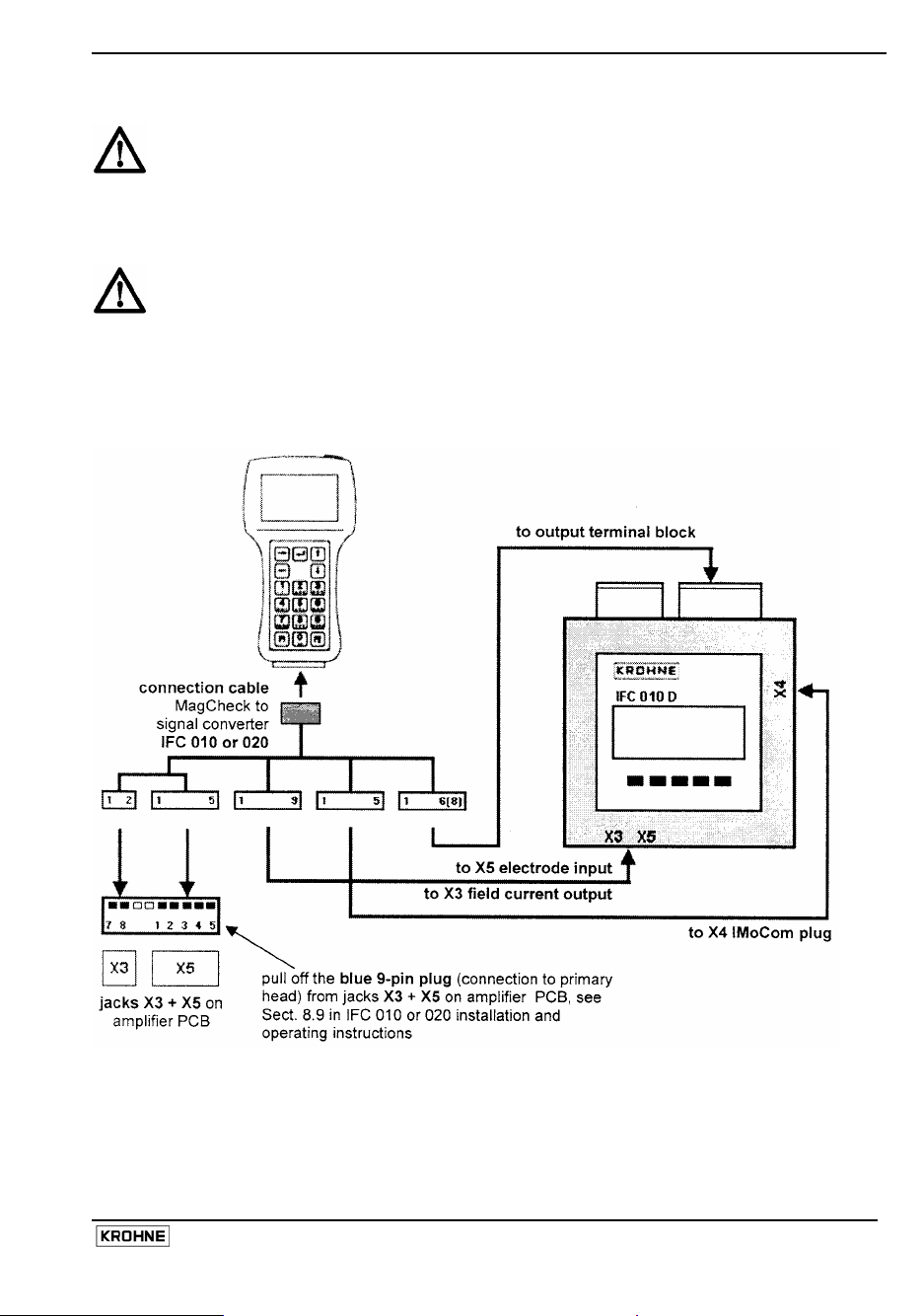
2.3 Connection diagrams
For use of MagCheck as precision flow signal calibrator for detailed manual
verification of converters Connections to flow head (field coils and electrodes) are
not needed.
Please note!
In the drawing of IFC 010 manual in Sect. 7.5 the jacks X1 and X4 were named wrong:
X1 must be X3 and X4 must be X5!
Connection MagCheck IFC 010 or IFC 020
MagCheck 7
Page 8
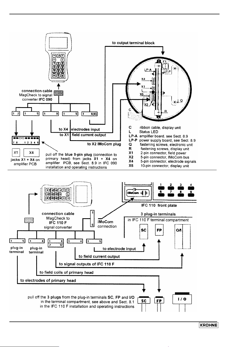
Connection MagCheck IFC 090
Connection MagCheck IFC 110 F
8 MagCheck
Page 9
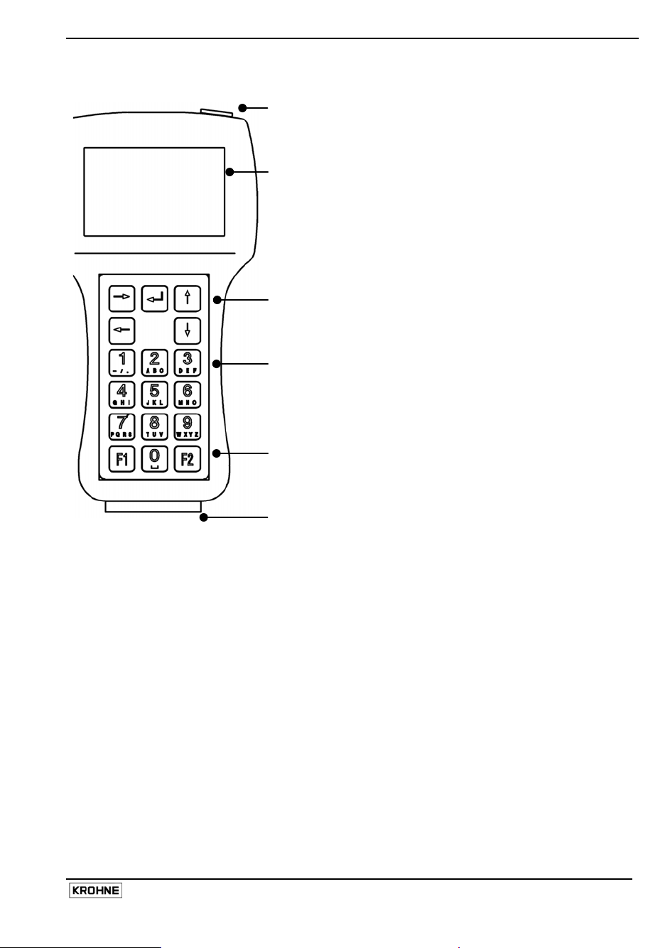
2.4 User interfaces
Connector for external power supply
(necessary only for download of verification data into PC)
Display
4 rows, 16 digits each
Backlit with external power supply
Arrow keys
• Entering into a menu (→)
• Stepping from digit to digit (→ ←)
• Increasing or reducing values (↑ ↓)
• Confirmation of entered data (↵)
• Stepping to the next (sub-)menu (↵)
• Returning to the main menu (↵)
Alpha-numerical keys
• Entering values,
• menu number
• Texts
F1 key
• start of MagCheck without IMoCom connection
F2 key
• For encoded access to MagCheck Service Menu only, no
function for verification
25-pole connector for
• converter verification cables
• PC-data transfer cable
2.5 Starting phase
After connection to converter and after power supply of the converter has been switched on
MagCheck will start a self test, checking all its EEPROM data for their validity. After it will signal
"OK" (in case of an error it will indicate "ERROR"), for approximately 5 seconds.
2.5.1 With IMoCom converters (IMoCom interface connected)
Next step is automatic start of communication with the IMoCom Bus of the IFC. After indicating :
"Test of communication", MagCheck locks in onto the IMoCom Bus of the IFC. It will read the
settings of the IFC and start to simulate a 100% signal.
2.5.2 With Non-IMoCom Converters or IMoCom-interface not connected
If there is no communication MagCheck will ask you to press "F1". and will stay in Menu 1.0 until
settings are entered (see below). All meter parameters data in menu 1.2 must be entered
manually.
If energy (field current level) received by MagCheck is too low, MagCheck display will flicker and
MagCheck will not start. This can be caused by:
• poor connection or defective cable / connector connecting field current to MagCheck
• a defective field current supply of the converter
• You have connected to an IFC040 converter
MagCheck 9
Page 10
←
↑
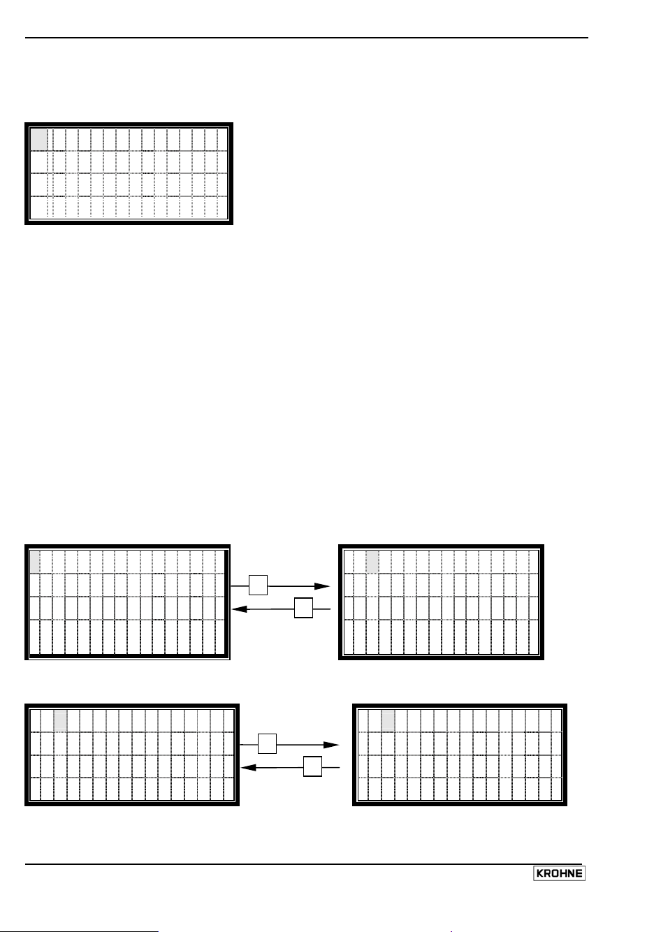
2.6 How to operate the menu
2.6.1 Display in main menu
There are three main menus indicated with x.0.
1 . 0 o p e r a t i o N
I Mo C o m - B u s ) (
f i e l d c u r r e n T + -
Menu line
Indication line
Status line for IMoCom connection
Status line for field current
In the main menu display, the two last lines represent status lines.
The IMoCom-Bus status line displays the actual status of the IMoCom connection as follows:
() Two moving brackets IMoCom present, IMoCom data transfer operating
() Two static brackets IMoCom present, no data transmission window present
no No IMoCom connected
The field current status line displays the actual status of the field current as follows:
+ - Plus, minus Correct (field current is switching from positive to negative current and vice
versa)
+ Plus Positive DC or pulsating DC (defective converter, negative half wave
missing)
- Minus Negative DC or pulsating DC (defective converter, positive half wave
missing)
No indication No current (defective converter, no field current)
The indication lines are used to show error messages.
2.6.2 Selecting menus and changing data
Moving the cursor
Cursor position is indicated by grey blinking background
1 . 0 o p e r a t i o n
I M o C o m - B u s ( )
f i e l d c u r r e n t + -
Cursor to the right
→
Cursor to the left
1. 1 t e s t MI D
I M o C o m - B u s ) (
fi el d cur r ent + -
Changing the numbers
Alternatively the corresponding numerical key can be used
3 z e r o s e t
1 .
I M o C o m - B u s ) (
f i e l d c u r r e n t + -
Increase number
↓
Decrease number
1. 4 si mul at i o n
I M o C o m - B u s ( )
f i e l d c u r r e n t + -
10 MagCheck
Page 11

↑
←
↵
Changing the Texts (Units)
When changing the units, the values are converted automatically
f u l l s c a l e
0 2 48 . 0
m 3 / h r
Selecting the next
text
↓
Selecting the
previous text
Changing from text (Unit) to numbers
f u l l s c a l e
068. 8 9
l / s
f u l l s c a l e
0 2 4 8 . 0
m 3 / h r
To numbers
→
To text
f u l l s c a l e
0
248. 0
m 3l / h r
Changing to submenus
3 .
1 l a n g u a g e
I M O C o m - B u s )
f i e l d c u r r e n t +
To submenu
→
(
- Back to main menu
l a n g u a g e
Engl i sh ( G B )
Fr ench ( F )
Ge r m a n ( D )
2.6.3 Initial settings of MagCheck
The only necessary initial setting is selection of the user language. Connect MagCheck to an IFC
XX0 or connect to a power outlet using its power adapter. In the latter case
• Press F1 to stop MagCheck’s search for an IMoCom interface
• Select Menu 3.1
• Press button → and select language English, German or French by the ↑↓ buttons
• Confirm selection by ↵
MagCheck 11
Page 12

3 Description of MagCheck menu functions
3.1 Menu structure
The menu of MagCheck has the following functional parts.
Menu Text Description
1.0 Operation Operation menu, main menu
1.1 Test MID Automatic verification menu for electromagnetic flowmeters
with IMoCom- converters
..1.2 – 1.8 Menu for manual calibration test of converters
1.2 Parameter Calibration test menu, entering meter data
→ Diameter
→ Full scale
→ Primary constant
→ FCS nominal
1.3 Zero set Zero setting
1.4 Simulation Generation of flow signals, adjustable in 0.1%-steps of full
1.5 Curr. output Display of true value (IMoCom converters only) and actual
1.6 Pulse output Display of true value (IMoCom converters only) and actual
1.7 Field current Indication of field current, displaying
1.8 Hardw. Info Display of:
1.9 Reset Reset menu (On IMoCom converters only)
2.0 Test Information menu
2.1 Device Info Display of MagCheck Serial number, software version and
3.0 Install Installation menu (main menu)
3.1 Language Language setting. English, French, German
3.2 Data transf. Data transfer menu from MagCheck to PC
DN 2.5 – 3000 mm/0.1 – 120 inch
Full scale value for flow Q=100%
(available display values: m3/hr, Liter/hr, USGal/min, l/s)
See EMF tag plate
Nominal field current value
scale value
value
value
• Positive current
• Negative current
• Sum of positive and negative current
• Field frequency
• Software ID of the respective modules
• Actual status information
(IMoCom converters only)
calibration date
12 MagCheck
Page 13

3.2 Automatic verification with KROHNE IMoCom converters
3.2.1 How to start verification
Menu Explanation Display Details
1.0 Operation
1.1
Test MID
Next screen 1.1 Test MID Starts automatic verification of flowmeter with
KROHNE IMoCom. All data will be verified and
stored in MagCheck.
Next screen
inputs xx/70: Number of stored verification files (e.g.
11/70), not transferred to the PC before. A total of
70 files can be stored. In this example 59
verifications can be made before memory is full.
date Enter actual date (DD/MM/YY). This will allow PC
program to correctly assort verifications in trend
analysis. Attention: No plausibility check! Check
carefully!
tag number All signs on the MagCheck keyboard may be used
for entering the tag number. Method is the same
as typing an SMS on a cell phone.
Entered Tag Number will be used as identifier at
download into PC. You may use up to 16
characters.
Next screen measurement Test conditions must be defined
(Select acc.
to test /
process
conditions
using ↑↓.
This will
allow
MagCheck to
select the
correct
verification
program)
pipe full
pipe empty
no pipe
filled with liquid
Electrode resistance will be tested via liquid.
With empty pipe the measured electrode
resistance will not comply with full pipe specs.
Result: Error statement in verification certificate
empty, clean, dry pipe
Electrodes will be tested for insulation. With a full,
wet or contaminated pipe, the measured electrode
resistance will not comply with empty pipe
specifications. Result: Error Message in
verification certificate
Converter verification only
No verification of flow tube.
Process
Enter type, other data
liquid
Next screen name user Enter name of MagCheck operator
(Select by
↑↓)
start? Select "back" or "yes"
back Will allow you to step back and check and correct
all data as entered above.
yes
Selecting yes and pressing ↵ will start automatic
verification run.
→
→
↵
↵
↵
↵
↵
MagCheck 13
Page 14

3.2.2 Explanation of the automatic verification run (verified data)
Converter data Data indicated and stored
Measurement of the field current Calibrated and actual value [mA]
Measurement of field frequency Act frequency [Hz]
ADC linearity and accuracy test at 25% of full scale 1)
ADC linearity and accuracy test at 50% of full scale 1)
ADC linearity and accuracy test at 75% of full scale 1)
Output of input amplifier and
analogue to digital converter: True
and act. value [% of full scale]
ADC linearity and accuracy test at 100 % of full scale 1)
Testing of the 1st calibration point P04 for current output 2)
Calibrated and actual value [mA]
Testing of the 2nd calibration point P20 for current output 2)
Testing of the 1st pulse output with f = 500 Hz 3) True and actual value [Hz] for
f100% = 1000Hz
If flowhead is tested as well
Measurement of field coil resistance Coil resistance (Ohms)
Measurement of resistance of electrode 1 4)
Measurement of resistance of electrode 2 4)
Measurement of isolation resistance of field coils
Resistance values are measured.
Display of subsequent voltage
levels and resistance values
Following the measurement, the measured data are stored in the MagCheck.
1) ADC test verifies accuracy of input amplifier and analogue to digital conversion of flow signal
During this test the GK of the converter is temporarily set to factory test conditions GK = 2.500.
At end of verification the GK will be reprogrammed automatically by MagCheck to original data.
2) mA output tests verify compliance of mA output with factory calibration settings
Time constant T settings via IMoCom is reduced by MagCheck to allow for sufficiently fast
settling of mA output and pulse output. At the end of the verification, the time constant will be
reprogrammed automatically by MagCheck to original data.
3) For test of frequency / pulse output setting of this output will be temporarily programmed by
MagCheck to 1000 Hz at full scale flow. At end of verification frequency / pulse output will be
reprogrammed automatically by MagCheck to original data.
4) If mode "Empty pipe" has been selected under MagCheck Function 1.1 electrode insulation
data are measured, displayed and stored.
In case of power interruption during flow meter verification e.g. by interruption of wiring, field current
supply etc. the setting of GK, pulse output and time constant must be checked and eventually
reprogrammed manually. Such an interruption is indicated by MagCheck after its restart with the
warning message: Last meter not re-programmed.
3.3 MagCheck as manual flow signal calibrator
3.3.1 Menu for manual calibration with IMoCom connection to IMoCom converters
MagCheck IMoCom connector must be connected to the IMoCom connector of the converter.
Note down all data settings and readings in a paper print of the Excel spreadsheet
“MagCheck_Verification_Listing.XLS” (see Appendix 1). After transfer of these data into this file,
error calculations and a protocol will be created automatically. Main menus must be selected
manually.
14 MagCheck
Page 15

Menu Explanation Display Details, recommended actions
1.2
Parameter
1.3
Zero set
1.4
Simulation
Menu for meter data.
With MagCheck
connected to IMoCom,
MagCheck will
automatically read
these data from the
converter.
Shows actual zero
setting as stored in
IMoCom converter.
Verifies calibration and
linearity of ADC, current
(1.5), pulse output (1.6)
by a precision flow
signal in 0.1% steps of
Full scale (see 1.2)
1.2 Parameter
Diameter Note the value displayed.
Full scale Q100% Note the values displayed.
Primary constant
Note the value displayed.
GK Value
FCS nominal Note the value displayed.
1.3 Zero set
Zero value
(units as full scale)
No changes possible.
Read and note.
1.4 Simulation
True value
(% + physical
units)
Actual value
Enter desired flow value (%).
Note % setting carefully.
Note true value [%].
Note act. value [%].
(% + physical.
units)
Act. value is ADC
value.
1.5
Current
output
1.6
Pulse output
1.7
Field current
1.8
Hardw. info
Shows current output at
flow as entered under
1.4
Shows pulse output at
flow as entered under
1.4
Shows field current
peak to peak (FCS),
pos., neg.
Shows software
versions + status
information according
to Function 2.2 of
IMoCom converters
1.5 Current output
True value [mA]
Actual value [mA]
1.6 Pulse output
True value [Hz]
Actual value [Hz]
1.7 Field current
True value [mA]
Actual value [mA]
1.8 hardw. Info
ADC
X.XXXXXX
Texts as
"Warning"
YYYYYYYYYY
Next module
X.XXXXX.XX
Note true value [mA].
Note act. value [mA].
Note true value [Hz].
Note act. value [Hz].
Note true value [mA].
Note act. value [mA].
Note data.
Eventual warning relates to
status info (numbers in 4th row)
(default no warning
0000000000).
Continue to step through by ↵
until last device has been shown.
Texts as
"Warning"
YYYYYYYYYY
1.9
Reset
Resets MagCheck and
re-starts
communication to
IMoCom converter
1.9 Reset New start, if you suspect a
system hang-up.
no
yes
Select using ↑↓.
On "yes + ↵" system will re-start
and return to Menu 1.9. All data
entered manually will be
replaced by default settings.
3.3.2 Menu for manual calibration of converters without IMoCom connection
Note down all set and measured data in a copy of “MagCheck_Converter_Cal_Prot.XLS” (see
Appendix 1). Main menus must be selected manually. Connect MagCheck and press F1.
MagCheck 15
→
↵
↵
↵
↵
→
↵
→
↵
→
↵
→
↵
→
↵
→
↵
↵
→
Page 16

Menu Explanation Display Details, recommended actions
1.2
Parameter
MagCheck starts
with KROHNE
standard
converter default
settings
Actual
parameters
listed right acc.
to meter setting
must be entered
manually acc. to
flow meter type
plate.
1.2 Parameter Menu for entering meter data.
Diameter DN 2.5 – 3000 mm / 0.1 – 120 inch Select
using ↑↓.
Full scale
Select physical unit using ↑↓.
(m3/hr, Liter/hr, USGal/min, l/s)
Enter full scale value for Q100% acc. type
plate or actual setting. In case of data
outside of meter range max / min values
are shown.
Primary
constant
FCS nominal
Enter GK / GKL acc. type plate. Take care,
no plausibility check.
Enter nominal field current [mA]:
IFC 010 125
IFC 020, 090, 110, 210: 250
SC80, IFC 080, 200 125
T900 000
1.3
Zero set
Allows
MagCheck zero
adjustment
1.3 Zero set
Default
000.000
For standard tests use default.
For precision tests follow 3.4.2.
Physical unit as
set under 1.2
1.4
Simulation
Verifies
calibration and
linearity of ADC,
current (1.5),
1.4 Simulation
True value
in % + phys.
units)
Enter desired flow value (%).in 0.1% steps
Read converter display, note % and
flowrate.
pulse output
(1.6) by a
precision flow
signal of Full
scale as under
1.2
1.5
Current
output
Shows current
output value at
flow rate (%) as
entered under
1.5 Current
output
Actual value
[mA]
Read, note mA values.
1.4
1.6
Pulse output
Shows pulse
output value at
flow rate (%) as
entered under
1.6 Pulse
output
Actual value
[Hz]
Read, note indicated pulse [Hz] rate.
1.4
1.7
Field current
Shows field
current peak to
peak (FCS),
1.7 Field
current
Act. value [mA] Note act. values [mA].
pos., neg.
1.8
• In this operation mode menus 1.8 and 1.9 have no function.
Hardw. info
1.9
Reset
→
↵
→
↵
↵
↵
→
→
↵
→
↵
→
↵
→
↵
16 MagCheck
Page 17

3.4 MagCheck Menu functions for manual calibration test
With IMoCom converters and IMoCom connected to MagCheck, MagCheck reads all parameters
(as under Function 1.2 and 1.3 of the converter). So accuracy data of the converters will be tested
under original setting conditions. If test shall be done using deviating parameters IMoCom
connection must be disconnected, MagCheck must be restarted (e.g. by shortly pulling cable
connector off and plugging in again. Descriptions below, how to enter data into Function 1.2 and 1.3
mainly refer to non-IMoCom converters.
3.4.1 Function 1.2 Parameters
Select with keys ↑ and ↓. Go to subfunction ,,Full scale value” with key → or ←.
Full scale value Q
For test under conditions as installed, enter the actual setting of full scale Q100% as shown on type
plate of the converter or in the documentation of this site. If different full scale values are entered
into the converter and into the MagCheck mark the maximum and minimum flow velocity limits for
full scale settings.
Min- /max-values of Q100%: The maximum and minimum full scale values are subject to nominal
diameter (DN) and the flow velocity (v). These limits are given in KROHNE documentation, e.g.
Installation and Operating Instructions of related converters. If these should not be accessible, the
minimum and maximum flow rates dependant on meter size with metric units may be calculated in
m3/hr as:
%100
min
1
%00
max
All IMoCom converters and AQF 070, SC80A, SC80 AS, IFC 200, IFC 200E, SC100A , SC100AS:
V100%
:0.3 m/s and V100%
min
Change to subfunction ,,Primary constant” with key ↵.
Primary constant GK
Enter Primary Constant GK / GKL acc. to type plate of signal converter or flowhead. Limits: 1.000 to
9.999.
Go to subfunction „FCS nominal” with key ↵.
Field Current Supply nominal
Enter nominal field current [mA]:
IFC 010 125
IFC 020, 090, 110, 210, SC 100 250
SC80, IFC 080, AQF 070, IFC 200 125
T900 000
Back to menu 1.2 Parameter by pressing ↵.
3.4.2 Function 1.3 Zero set
Press → key.
Enter the zero point: Minimal zero point: -10% of the full scale value; Maximal zero point: +10% of
the full scale value, e.g. Full scale is 100 m3/h. Minimum zero point is -10m3/h and maximum zero
MagCheck 17
100%
π
]hr/m[Q
=
4
π
]hr/m[Q
=
4
23
23
:12 m/s. For T900: V100%
max
[]
%100
min
%100
max
[]
10006.3s/mv]mm[DN
÷×××
10006.3s/mv]mm[DN
÷×××
:0.5 m/s and V100%
min
:9.999 m/s
max
Page 18

point is +10m3/h.
With Non-IMoCom converters zero must be entered manually. Set function 1.3 Zero set to 000.000
with unit acc. setting of converter. To find a correct zero setting for the calibration test, step to Menu
1.4 Simulation. Set simulation value to 000.0%. Read indication from converter display. If indication
is too noisy, increase time constant of converter to 10s.. 30s. Wait 10 time constants, until indication
is stable. Read indication on converter display, enter read value with inverted sign into menu
Function 1.3 Zero Set.
Example:
Indication is -0.13 m3/hr.
Enter + 0.13 m3/hr (select sign by using ↑↓) into Function 1.3 Zero Set.
Back to menu 1.3 Zero setting by pressing ↵.
3.4.3 Function 1.4 Simulation
Press → key.
Entering a value here will simulate flow by creating a precise calibrated flow signal as input signal
for the converter. The outputs of the converter follow this calibrated flow signal level.
The simulated flow value may be set between –999.9% and +999.9% of the full scale as set or read
under "Function 1.2 Full Scale Value". For normal tests, setting shall be within ± 100.0%.
If the maximum signal level of MagCheck is exceeded, the warning "error message: simulation
parameters, check" is shown on the MagCheck display.
Back to menu 1.4 Simulation by pressing ↵.
3.4.4 Function 1.5 Curr. Output
Press → key.
Display according to setting of Function 1.4 Simulation.
Example: Function 1.4 Simulation value set to 50.0%, Converter settings I0% = 4 mA, I100%= 20
mA).
Display Function 1.5:
MagCheck Display Head Line Current output
No IMoCom connection to converter Act. 11.998 mA
True 12.000 mA With IMoCom-converter and IMoCom
connection from MagCheck to converter
Act. 11.998 mA
Back to menu 1.5 Field current by pressing ↵.
3.4.5 Function 1.6 Pulse output
Press → key.
Display of the measured output frequency from the pulse output in pulses/second.
Example: Function 1.4 Simulation value set to 50.0%, f100%= 800 Pulses / second)
Display Function 1.6.
MagCheck Display Indication Headline: Pulse output
No IMoCom connection Act. 399,8 Hz
With IMoCom-converter and IMoCom
connection from MagCheck to converter
True 400,0 Hz
Act. 399,8 Hz
18 MagCheck
Page 19

Attention: With low pulse frequency settings MagCheck will change to measuring pulse period.
Example: Full Scale of converter Q
is 100 m3/hour, Pulse Rate of converter is set to 1
100%
pulse/m3. Accordingly the converter will send 1 pulse every 36 seconds, if Function 1.4 Simulation
has been set to 100%.
With setting of Function 1.4 Simulation to 10% it will last very long until a value can be indicated.
In such cases it will be better to increase pulse rate setting of the converter by a factor of 10, 100 or
to 1000 Hz for this test. Make sure to restore the original settings after completion of the test!
Back to menu 1.6 Pulse output by pressing ↵.
3.4.6 Function 1.7 Field Current
Press → key.
Display of the measured field current (all values in mA):
FCS = peak to peak field current
pos. = the positive half wave
neg: = the negative half wave
Frequency = actual value of field frequency
Back to menu 1.7 Field current by pressing ↵.
3.4.7 Function 1.8 Hardw. info
Press → key.
This menu may be used on IMoCom Converters only after IMoCom connection has been
established. Hardware Information and Status Information acc to menu 2.2 of IFC 010, 020, 090,
110 are shown.
Display of Software I.D.-no. and status message of the connected module: In this menu, an 8position software number and a 10-position status code are stored. These status codes enable a
quick and simple diagnosis of your flow meter. The number of modules indicated depends on the
number of modules present in the flow meter. Should one module report a fatal error or a warning,
this will be shown in the fourth line of the display.
Change to next status report by pressing ↵.
Back to menu 1.8 Hardware Info by pressing ↵.
3.4.8 Function 1.9 Reset
Reset Function with IMoCom converters only! Press → key.
In some cases, it can be useful to perform a restart of a device. To perform a restart, the “Reset”function can be chosen in this menu. Only possible with IMoCom-connection between MagCheck
and IFC. Should a restart be performed without the MagCheck connected to the mains supply, the
MagCheck will also be restarted and the main menu will be shown again
3.4.9 Function 2.1 Device Info
Press → key.
Following information is displayed:
Device Info
SN (Serial Number): XXXXXXXX
SV (Software Version): XX.XXX.XXX.X
CalDate (calibration Date): XX.XX.XX
Back to menu 2.1 Software by pressing ↵.
MagCheck 19
Page 20

3.4.10 Function 3.1 Language
Press → key.
Select language of MagCheck display texts: English (GB), French (F) or German (D). The selected
language appears in flashing text.
• Select with ↑ and ↓
• Confirm with ↵ (Data change accept)
• Select choice with ↑ and ↓, confirm with ↵
• Back to menu 3.1 Language by pressing ↵
3.4.11 Function 3.2 Data transfer from MagCheck to the PC
Connect MagCheck to PC. The external power supply must be connected to MagCheck. The 25-pin
PC connector of the RS 232 cable (supplied with MagCheck) must be connected to the MagCheck
connector, the 9-pole connector to RS232 COM port of the PC COM port. On the PC, the
MagCheck PC program must be active. During transfer of the data from MagCheck to PC, the
message “Data transfer” is shown on the MagCheck display.
Press → key.
The display will show, that MagCheck is now ready for data transfer. Data Transfer to the PC will
be started by clicking "Read verification data from MagCheck" on the PC screen.
Back to menu 3.2 Data transfer by pressing ↵.
After data transfer the according memory areas in the MagCheck will be released for
overwriting by new files, this means all downloaded data are erased from
MagCheck.
20 MagCheck
Page 21

4 Using MagCheck with a PC
4.1 System specifications
To be able to install the MagCheck system on to your PC, the following specifications apply:
• MS Windows
• MS Windows
®
-PC
®
95, 98, 2000, NT, XP
• > 32 MB memory, >32 MB free space on hard disk,
• CD-ROM drive
• Free Com Port: RS 232
• Mouse, keyboard, monitor, printer
4.2 Installation PC software
Insert the CD into the CD drive of your PC and
follow the instructions of the Set-up-program.
During installation you will be asked for a
password. To work without password leave the
field blank and click ok. There is no way to
recover a lost password. After installation and
clicking on the MagCheck icon on the desktop
the main screen of the MagCheck main menu
will appear:
4.3 Settings of MagCheck PC software
4.3.1 Selection of the PC program language
Enter Menu Extra. Select Language, select:
English, Français, Deutsch or Nederlands. After
selection the program must be closed and
restarted.
4.3.2 Selection of the MagCheck Com-Port for download of verification data
Enter Menu Extra. Select "Serial port."
MagCheck PC- program checks the port of your computer and offers an appropriate selection.
Confirm.
MagCheck 21
Page 22

4.4 Connecting MagCheck to PC
• The 25-pin PC connector of the RS 232 cable
(supplied with MagCheck) must be
connected to the MagCheck connector, the
9-pole connector to RS232 COM port of the
PC COM port as configured above.
• The external power supply must be
connected to MagCheck.
• Any power adapter used with MagCheck
must meet safe separation regulations (IEC
950, SELV, safe electrical low voltage
regulations)
• The power supply adapter (FRIWO 7238/15)
supplied by KROHNE has been certified for
safe separation under office ambient
conditions (dry rooms).
Do not use this power supply
adapter in wet environments. Risk of
personal hazards!
4.5 Downloading and storing MagCheck verification data onto PC
• Start MagCheck PC-program. Connect MagCheck to PC.
• MagCheck will start searching for communication to an IMoCom interface. Press F1.
• Select MagCheck Menu 3.2. After pressing arrow → MagCheck will indicate "Ready for data
transfer".
• Click on MagCheck PC main menu, button: "Read flowmeter verification files from MagCheck".
• MagCheck PC program will ask : "Number of new flowmeter verification files: X (e.g. 1-70). Do
you want to download these flowmeter files?"
• Click "OK" and the following screen appears:
• If the meter has been verified for the first
time, select the lower radio button
("..flowmeter not known.."). Enter a file
name under which the flowmeter data will
be stored. Recommended e.g.: Customer
Company (abbrev) + Location +Tagname,
e.g. WaterSWW_Kingsville_FIC107
• If the related flowmeter has been verified
before and the actual verification data
should be added to its history, select the
upper radio button and select the correct
device identification from the pull-down
menu, to which this new verification file
should be added. The downloaded data
will now become part of the selected
meter history!
• With the button "Cancel..." data sets may
be excluded from download.
• Button "Abort reading...." will stop
downloading of verification data.
Verification files which not have been downloaded will remain in MagCheck memory.
22 MagCheck
Page 23

4.6 Exporting and importing verification files from / to floppy or hard disk
4.6.1 Menu “File”
File format of all verification export- and importfiles is *.MCK.
For exporting verification files which have been
downloaded from MagCheck into PC select
menu File, Export.
4.6.2 Exporting MagCheck verification files
After clicking on "Export..." a screen appears,
which allows selecting a directory where to store
the export file and entering a file name.
The upper pull-down list “Store in:” allows for
selecting an appropriate directory for storing the
export file. The lower box allows for entering an
appropriate file name (e.g.
MagCh_Date_All_UserComp.MCK).
The list below shows all verification data files
stored in file MagCheck.MCK in the MagCheck
data base. Deselect files which should not be
exported by clicking on the marker field. Click on
OK, the marked data sets will be exported to the
file.
4.6.3 Importing MagCheck verification files
Select: Menu File, Import. Select drive /
directory, *.MCK file, Click on "Open". Window
"Load MagCheck Import-and export file" (see
right) will open. Selected data sets will be
imported in to the meter data bank of the
MagCheck program.
If one of these flowmeter data sets already exists
in the MagCheck PC data bank, a warning will
appear. If the existing flowmeter data set is to be
replaced by the import file, click "yes".
MagCheck 23
Page 24

4.7 Trend analysis
The trend analysis shows all
measured data in detail. Its
graphic presentation of all data
and the related error limits
allows for easy checking of
stability, drifts of all measured
parameters.
Click on tab "Measurement
results" on MagCheck PC
program main screen.
Select meter to be shown on
pull-down list "Device
identification"
(example: FT-1)
Tab "Info" will show a listing of
meter data incl. order number,
converter number and all
settings as read by MagCheck.
Pull-down lists will allow selection of a sequence of meter verifications in the meter history.
As an example the following view shows meter FT-1, parameter "ADC 100%" for verifications 3 to 6
out of a sequence 1 to 7. Any other parameter may be presented in the same way.
Numerical data for the related parameter are shown at the right side. Dotted lines indicate the error
limits for the related parameter. These limit data are listed just above the diagram, too.
In case of the first verification (no history) or selection of one verification only (e.g. from "Parameter
6" to "Parameter 6" results are shown as numerical values.
24 MagCheck
Page 25

4.7.1 Information "Flowmeter has been changed..."
This information will appear if, compared to the first verification, one of the following parameters has
been changed: GK, nominal diameter , Full scale, I0%, I100%, settings of pulse output.
4.7.2 Printing the Trend Analysis
Open the specific flowmeter file.
On Main Menu Bar select "File", "Print", "Page
setup". Adjust page settings.
Select: "File", "Print", "Trend analysis”.
4.7.3 Trend Analysis Print selection menu
This menu allows for selection of:
• the device
• the parameter sequence to be printed
• print preview on the monitor,
• printing as Adobe Acrobat-Reader .PDF-file,
which may be stored or sent by e-mail
• or print on any printer connected to the PC.
4.7.4 Printing verification certificates
On Main Menu Bar select: "File", "Print", "Page
setup". Adjust page settings.
Select : "File", "Print", "Certificate".
This menu allows for selection of the device, the parameter set (verification) to be printed, print
preview on the monitor, printing as Adobe Acrobat-Reader *.PDF-file, which may be stored, sent by
e-mail or printed on any printer connected to the PC.
MagCheck 25
Page 26

5 Interpretation of verification results
Check in the trend analysis which parameters are exceeding their limits. Most common causes are
outlined below.
5.1 Accuracy data ADC, field current, mA or frequency output
ADC is the primary signal processing. It includes input instrumentation amplifier and analogue to
digital conversion of the flow signal voltage. Accuracy of ADC and field current directly influence
accuracy of any output of the electromagnetic flowmeter. If accuracy of ADC, mA or frequency
output, or field current is wrong: exchange converter electronics.
5.2 Coil resistance
Coil resistance value is dependent of coil temperature during verification. Coil temperature again is
dependent on ambient temperature and on medium temperature in the flow tube of the magnetic
flowmeter. Temperature coefficient is 0.4% per °C (0.2% per °F). Two failure modes can be
detected:
• Resistance is zero or far below plausible value: Check cabling, connectors, terminals to field
coils on short circuits.
• Resistance is high: Check cabling, connectors, terminals to field coils on interruptions or poor
contact.
Check connectors / connections below the terminal board. If these are ok and coil resistance
remains infinite or zero, interruption or short-circuit of an internal connection is possible (but
extremely rare). In that case, the flowhead must be exchanged.
5.3 Electrode resistance with full pipe
In general: Electrode resistance with full pipe depends on conductivity (σ) of the liquid. Conductivity
depends on liquid type, concentration, temperature. Change of electrode resistance between two
verifications only is significant as long as precisely the same liquid with same concentration and
temperature will flow through the flowmeter without creating any deposits. Electrode resistance
values may be estimated from electrode diameter “d” and conductivity (σ) according to following
formula:
[]
=Ω
kR
Electrode
This formula may be used for approximate plausibility checks if the results of electrode resistance
measurements are outside of the measuring range of MagCheck. The results of this formula may
show a deviation to true value of electrode resistance as indicated by the tolerance data.
Electrode resistance with full pipe very high: Check cabling to electrodes (signal cable, connector in
remote flowhead connection box) on interruption. Remove meter from line, clean electrodes and
grounding rings.
Asymmetric electrode resistance: Differences in electrode 1- and 2 resistance values by more than
±50% may be caused by:
• Heavy coating (contamination) on one of the electrodes (Countermeasure: Clean electrodes)
• Beginning short circuit of one electrode, e.g. by contamination with highly conductive matter
(Action: Clean electrodes and liner carefully) or by electrode leakage.
Electrode leakage and conductive deposits can be confirmed by verification with empty pipe.
Select “Pipe Empty” in Menu 1.1.
26 MagCheck
1000
[] [ ]
×
/
cmScmd
µσ
100% / 50%:Tol.
+−
Page 27

5.4 Electrode resistance with empty pipe
Low resistance of electrodes with empty pipe may influence accuracy. This may be caused by
humidity on terminal boards in converter and flowhead, defective signal cables at separate meters or
electrode leakage. With empty, clean and dry pipe the electrode resistance must be > 10 MOhms.
The MagCheck limit of > 6 MOhms considers minor insulation degradation on signal cable and
lining.
• Check converter signal cable connectors, flowhead
terminals and PC-board. Clean, dry?
• Bottom side of PC-board in flowhead connection box
and connector. Clean and dry thoroughly!
Disconnect signal wires at flowhead terminals 2, 3.
• Do not disconnect cable shield terminals 1, GND
• Make sure that open cable ends are clean, dry and do
not contact each other or any flow meter part.
• Repeat verification. MagCheck result now:
↓ OK?
• Cable is ok. Investigate flowhead connection box:
Terminals and PC-board clean, dry?
(also: check bottom side and connector)
• Clean and dry thoroughly! Assemble again.
• Disconnect all cables to converter
• Do insulation test on flowhead terminals:
• Terminal 2 to 1 or GND (≤ 100 VDC).
• Terminal 3 to 1 or GND (≤ 100 VDC).
↓ OK?
Resistance electrodes with empty pipe OK
Signal cable
→ NOT OK?
defective,
low insulation
Exchange!
Take meter out.
Clean liner.
Remove deposits.
→ NOT OK?
Dry liner.
Repeat insulation
tests on terminals
← ←
2, 3 to 1 / GND
↓ ↓
OK?
Test coil insulation as below/
Contact KROHNE.
→ NOT
OK?
↓
MagCheck 27
Page 28

5.5 Coil insulation
Coil insulation is a vital parameter for accurate function of a magnetic flowmeter. Causes for poor
insulation may be found in wet or defective field current cable, wet or dirty terminals and connectors
or liquid entrained in the meter body. What to do if result "Coil insulation" is "NOT OK":
• Check converter field current cable connectors,
flowhead terminals and PC-board. Clean, dry?
• Bottom side of PC-board and connector in flowhead
connection box. Clean and dry thoroughly!
Disconnect field current wires at flowhead terminals
7,8.
• Do not disconnect cable shield terminals 1, GND
• Make sure that open cable ends are clean, dry and do
not contact each other or any flow meter part.
• Repeat verification. Does MagCheck indicate
→ NOT OK?
Field current cable
defective,
low insulation
Exchange!
insulation > 10 MOhm? Now?
↓ OK?
• Cable is ok. Investigate flowhead connection box:
Terminals and PC-board clean, dry?
(also Bottom side and connector). Clean and dry
thoroughly! Re-assemble the cable connections.
→ NOT OK? Contact KROHNE
• Disconnect all cables to converter
• Do an insulation test (≤ 100 VDC) on flowhead
terminals 7 or 8 to 1 or GND > 10 MOhm?
Field coil insulation OK
↓ OK?
5.6 Limitations of accuracy statement
MagCheck is verifying all vital electrical data of the flowmeter and converter. The verification result
does not include factors as: deposits in flowtube, installation not according to installation rules,
gases in the liquid.
28 MagCheck
Page 29

6 Service and recalibration
6.1 Recalibration
MagCheck must be recalibrated annually. The calibration menu is indicated in Function 2.1 Device
Info.
For recalibration and/or repair please contact your local KROHNE representative.
6.2 Software
If there are any problems regarding the MagCheck software, please have the following information
ready and contact your local KROHNE representative.
• System: Microsoft Windows
®
98 / 2000 / NT4 / XP
• Type of processor
• Com port in use
• Type of flowhead (A-number)
• Type of signal converter (serial number)
• Description of error(s)
• MagCheck Export file (*.MCK) with statement, which device looks wrong
• Trend analysis (Adobe Acrobat reader *.PDFfile)
6.3 Spare parts
The following spare parts are available for MagCheck:
Spare part BaaN ordering number
MagCheck (in suitcase) complete replacement! XN00121100
Power supply adapter 100..230V to 15 V DC with plug adapter for
XN00121200
different plug standards
IFC 010 connecting cable XN00121300
IFC 020 connecting cable XN00121400
IFC 090 connecting cable XN00121500
IFC 110 connecting cable XN00121600
PC RS 232 connecting cable XN00121900
MagCheck CD (incl. MagCheck PC program, installation and operating
XN00122000
instructions, Excel spreadsheets for data processing)
Installation and operating instructions UK English (printed) XN00122100
Installation and operating instructions German (printed) XN00122200
Installation and operating instructions French (printed) XN00122300
Appendix 1
MS Excel spreadsheets, available on the KROHNE MagCheck CD, allow for easier documentation
and evaluation of manual and automatic verifications of flowmeters. Keep printouts ready for use on
site.
MagCheck 29
Page 30

Documentation of automatic verification files
To make sure that verification files are documented and can be correlated to customer or tag
number even years after first evaluation, use the Excel spreadsheet
MagCheck_Verification_Listing.XLS. Take some print-outs with you whenever you leave for
verifications and document local situation and file names immediately on site. This will enable you
to add verification files adequately to previous taken verification data and to create a clear history.
30 MagCheck
Page 31

Documentation of data of manual converter calibration test
Data and readings in menu 1.2 to 1.7 during manual calibration test may be noted in a print-out of
spreadsheet MagCheck_Manual _Test_Report.XLS. These data may be easily transferred into the
Excel spreadsheet, which automatically calculates errors.
MagCheck 31
Page 32

Australia
KROHNE Australia Pty Ltd.
Unit 19 No.9, Hudson Ave.
Castle Hill 2154, NSW
TEL.: +61(0)2-98948711
FAX: +61(0)2-98994855
e-mail: krohne@krohne.com.au
Austria
KROHNE Ges.m.b.H.Austria
Modecenterstraße 14
A-1030 Wien
TEL.: +43(0)1-2 03 45 32
FAX: +43(0)1-2 03 47 78
e-mail: info@krohne.at
Belgium
KROHNE Belgium N.V.
Brusselstraat 320
B-1702 Groot Bijgaarden
TEL.: +32(0)2-4 66 00 10
FAX: +32(0)2-4 66 08 00
e-mail: krohne@krohne.be
Brazil
KROHNE Conaut
Controles Automaticos Ltda.
Estrada Das Águas Espraiadas, 230 C.P. 56
06835 - 080 EMBU - SP
TEL.: +55(0)11-4785-2700
FAX: +55(0)11-4785-2768
e-mail: conaut@conaut.com.br
China
KROHNE Measurement Instruments Co. Ltd.
Room 7E, Yi Dian Mansion
746 Zhao Jia Bang Road
Shanghai 200030
TEL.: +86(0)21-64677163
FAX: +86(0)21-64677166
Cellphone: +86(0)139 1885890
e-mail: ksh@ihw.com.cn
CIS
Kanex KROHNE Engineering AG
Business-Centre Planeta, Office 403
ul. Marxistskaja 3
109147 Moscow/Russia
TEL.: +7(0)095-9117165
FAX: +7(0)095-9117231
e-mail: krohne@dol.ru
Czech Republic
KROHNE CZ, spol. s r.o.
Sobe˘s˘ická 156
CZ-63800 Brno
TEL.: +420(0)5-45 53 21 11
FAX: +420(0)5-45 522 00 93
e-mail: brno@krohne.cz
Algeria
Argentina
Bulgaria
Camaroon
Canada
Chile
Columbia
Croatia
Denmark
Ecuador
Egypt
Finland
French Antilles
Greece
Guinea
Hong Kong
Hungary
Indonesia
Ivory Coast
Iran
Ireland
Israel
Japan
Jordan
Kuwait
Marocco
Mauritius
Mexico
New Zealand
Pakistan
Poland
Portugal
Saudi Arabia
Senegal
Singapore
Slovakia
Slovenia
Sweden
Taiwan
Thailand
Turkey
Tunesia
Venezuela
Yugoslavia
France
KROHNE S.A.
Usine des Ors
B.P. 98
F-26 103 Romans Cedex
TEL.: +33(0)4-75 05 44 00
FAX: +33(0)4-75 05 00 48
e-mail: info@krohne.fr
Germany
KROHNE Messtechnik
GmbH & Co. KG
Ludwig-Krohne-Straße
D-47058 Duisburg
TEL.: +49(0)203-301-0
FAX: +49(0)203-301 389
e-mail: krohne@krohne.de
India
KROHNE Marshall Ltd.
A-34/35, M.I.D.C.
Industrial Area, H-Block,
Pimpri Poona 411018
TEL.: +91(0)20-744 20 20
FAX: +91(0)20 -744 20 40
e-mail: pcu@vsnl.net
Italy
KROHNE Italia Srl.
Via V. Monti 75
I-20145 Milano
TEL.: +39(0)2-4 30 06 61
FAX: +39(0)2-43 00 66 66
e-mail: krohne@krohne.it
Korea
Hankuk KROHNE
2 F, 599-1
Banghwa-2-Dong
Kangseo-Ku
Seoul
TEL.: +82(0)2665-85 23-4
FAX: +82(0)2665-85 25
e-mail: flowtech@unitel.co.kr
Netherlands
KROHNE Altometer
Kerkeplaat 12
NL-3313 LC Dordrecht
TEL.: +31(0)78-6306300
FAX: +31(0)78-6306390
e-mail: postmaster@krohne-altometer.nl
KROHNE Nederland B.V.
Kerkeplaat 12
NL-3313 LC Dordrecht
TEL.: +31(0)78-6306200
FAX: +31(0)78-6306405
Service Direkt: +31(0)78-6306222
e-mail: info@krohne.nl
Norway
Krohne Instrumentation A.S.
Ekholtveien 114
NO-1526 Moss
P.O. Box 2178, NO-1521 Moss
TEL.: +47(0)69-264860
FAX: +47(0)69-267333
e-mail: postmaster@krohne.no
Internet: www.krohne.no
South Africa
KROHNE Pty.Ltd.
163 New Road
Halfway House Ext. 13
Midrand
TEL.: +27(0)11-315-2685
FAX: +27(0)11-805-0531
e-mail: midrand@krohne.co.za
Spain
I.I. KROHNE Iberia, S.r.L.
Poligono Industrial Nilo
Calle Brasil, n°. 5
E-28806 Alcalá de Henares-Madrid
TEL.: +34(0)91-8 83 21 52
FAX: +34(0)91-8 83 48 54
e-mail: krohne@krohne.es
Switzerland
KROHNE AG
Uferstr. 90
CH-4019 Basel
TEL.: +41(0)61-638 30 30
FAX: +41(0)61-638 30 40
e-mail: info@krohne.ch
United Kingdom
KROHNE Ltd.
Rutherford Drive
Park Farm Industrial Estate
Wellingborough,
Northants NN8 6AE, UK
TEL.: +44(0)19 33-408 500
FAX: +44(0)19 33-408 501
e-mail: info@krohne.co.uk
USA
KROHNE Inc.
7 Dearborn Road
Peabody, MA 01960
TEL.: +1-978 535-60 60
FAX: +1-978 535 -17 20
e-mail: krohne@krohne.com
Overseas Representatives
Other Countries:
KROHNE Messtechnik
GmbH & Co. KG
Ludwig-Krohne-Str.
D-47058 Duisburg
TEL.: +49(0)203-301 309
FAX: +49(0)203-301 389
e-mail: export@krohne.de
Subject to change without notice
 Loading...